

Page 1

Instruction
Manual
VDV
CommanderTM
VDV501-097
ENGLISH
• TESTS
CABLES
• MEASURES
CABLE LENGTH
WITH TDR
• DETECTS
FAULTS
• DETECTS AND
MEASURES PoE
• LOCATES AND
IDENTIFIES CABLES
• TESTS ACTIVE NETWORK
• SAVE AND PRINT REPORTS
Page 2

ENGLISH
VDV Commander
™
Instruction Manual
FEATURES
The Klein Tools VDV Commander™ is a full-featured
voice/data/video cable tester which includes cable length
measurement, the ability to detect and/or identify PoE, link
status and link capability – all in one product.
• Tests Cables
• Measures Cable Length with TDR
• Detects Faults
• Detects and measures PoE
• Locates and Identifies & Cables
• Tests Active Network
• Reporting
• Link Light
• Cable Identification (up to 20 locations)
• Shield Detection
• Voltage Warning
• Low Battery Indicator
• Multiple-Style Tone Generator
• Color LCD Display
• Multiple Languages
• Imperial and Metric Results
• Auto Power Off
• Customizable Setup
• USB Interface
• Upgradeable Firmware
Page 3
GENERAL SPECIFICATIONS
• Dimensions: 6.8" L x 3.6" W x 1.85" D
(173 mm L x 91 mm W x 47 mm D)
• Weight:
• Operating Temperature: 32°F to 122°F (0°C to 50°C)
• Storage Temperature: -22°F to 140°F (-30°C to 60°C)
• Humidity: 10% to 90%, non-condensing
• Altitude: 10,000 ft (3,048 m) operating
• Voltage:
• Voltage Warning: At maximum Safety Extra Low Voltage
• Battery Life: 6 x AA alkaline batteries
• Enclosure: High-strength PC/ABS plastic with UL94, V0
• Drop Protection: 4 ft. (1.2 m)
• Languages: English, Spanish, French
• Measurement Method: Time Domain Reflectometry (TDR)
• Cable Measurements:
• Remote support:
• Power over Ethernet:
(at class 4) Identifies Mode A or B (pairs with PoE)
• Active Ethernet: Indicates advertised speeds of
• Tone Generation:
• Test Memory Storage:
• Safety Compliance: CE
• Disposal Compliance: WEEE
18 oz. (510 g) with batteries
• RJ Jack: 66V DC or 55V AC
• F-Connector: 50V DC or AC
limits (60V peak AC or DC). Measurement continues while
warning is displayed.
• Standby: 10 years
• Active: 20 hours (average)
rating with boot.
• Cable Testing and ID: up to 1,000 ft (305 m)
• Split Pair Detection: 3 ft. (1 m) to 1,000 ft. (305 m)
• Length: 0 to 1,500 ft (457 m), ± 5% and 1 ft. (0.3 m)
Supports 8 Test-n-MapTM ID remotes (RJ11/12/45)
Supports 20 RJ-45 and 20 F-Connector ID only remotes
Tests for IEEE 802.3af and IEEE 802.3at (PoE Plus) compliant PoE
Tests for classes and loads cable up to 25.5 watts
10/100/1000base-t half or full duplex. Can link to network
at 10/100base-t
Tone frequencies: 730 Hz and 1440 Hz
Stores up to 256 cable or network
tests with user defined names.
WARNINGS
To ensure safe operation and service of the tester, follow
instructions. Failure to observe these warnings can result in
severe injury or death.
The VDV Commander is designed for use on cabling systems
Safety Extra Low Voltage (SELV)
with
• Do NOT use the VDV Commander when the Voltage! icon
is present. The Voltage! icon turns on when the voltage
exceeds Safety Extra Low Voltage (SELV) rating of 60 Volts
peak AC or DC. Operating the VDV Commander when a
voltage source exceeds 60 Volts peak AC or DC may pose
a safety hazard for the user.
SYMBOLS:
WARNING: Potential for personal injury.
Caution: Potential for damage or destruction to equipment.
Always wear approved eye protection.
Do NOT use on energized circuits.
Conformité Européenne. Conforms with
European Economic Area directives.
This symbol indicates that equipment and its accessories
shall be subject to a separate collection and correct disposal.
or without voltage.
Page 4
ENGLISH
"Back"
Button
"Arrow"
Buttons
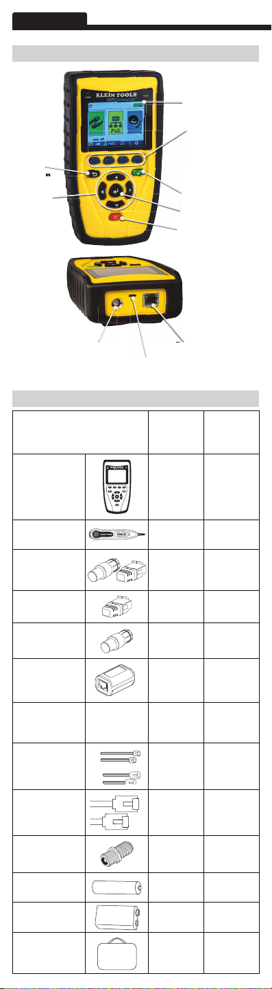
OVERVIEW
Full-color
LCD Display
Function Buttons
perform the
function on the
display above
each button
"Test" Button
"Enter" Button
"On/Off" Button
Coax
Connector
Description
VDV Commander
Tester
PROBEplus Tone
Tracing Probe
CoaxMap + LanMap
Starter Set ID
Remotes (1-5)
LanMap ID
Remotes (1-20)
CoaxMap ID
Remotes (1-20)
VDV Test-n-Map
ID Remote #1
Test Cable Micro USB to
USB A
Test Cable Universal
RJ12 Jumper, 9"
USB
Port
ACCESSORIES
VDV501-097
RJ45
Jack
Starter
VDV501-829
Test & Tone
Kit
Kit
Test Cable RJ45 Jumper, 9"
Coax Adapter Barrel, F-F, Female
AA Batteries (6)
9-Volt Battery (1)
VDV Commander
Carrying Case
Page 5

LCD SCREEN
The VDV Commander features a full-color graphic LCD screen.
Press any of the four blue buttons below the on-screen
icon to select that function. Alternately, you can use the side or
up/down arrows to scroll to desired
on-screen function and press the "Enter" button .
Types of Faults
Several possible error conditions on the cable are detected and
displayed on the screen of your VDV Commander.
Cable Fault Description
Miswire Cable’s wire connection does not follow
Open Wire connection is not continuous
Short A pair has a high resistance fault. This
Split A cable can be wired with correct
Length Displays the pair lengths found. Length
Network
Connectivity
PoE Displays results in red if voltages are
cabling standards.
throughout cable length.
occurs when the wires are making contact
with each other due to damage
or improper termination.
continuity but not with correct pairing.
This happens most when the cable is
terminated consistently at both ends but
in the wrong order.
discrepancies may be determined by these
results.
Displays network connectivity which
allows the user to determine if it is
different than expected.
lower than expected.
START-UP AND SHUT-DOWN
Follow instructions carefully and pay attention to warning
and caution symbols. Failure to observe warnings can result
in severe injury, death, and damage to the VDV Commander
tester.
On/Off
Turn unit On/Off – press the red "On/Off" button to
activate the VDV Commander or turn it off.
Auto Power Off
The VDV Commander automatically turns off to conserve
battery power if no input or activity is performed on the device.
See “setup” to adjust the length of time before automatic
power down.
SETUP
From the main screen, press the blue function button
on the far right below the “setup” symbol . Use the
up and down arrow buttons to scroll through
the Setup menu and to select an option.
Page 6

ENGLISH
• Use the up and down arrow buttons
navigate through the settings.
• Use the left and right arrow buttons to select setting.
• Use the up and down arrow buttons
the selected setting.
• Press the "Enter" button
• Press the left arrow to unselect a setting.
to accept your changes.
to
to change
Changing a Setting
• RJ45 VoP : VoP
Set the VoP to be used to measure RJ45 cable.
• Coaxial VoP : VoP
Set the VoP to be used to measure coaxial cable.
• TIA568A/TIA568B: Set the RJ45 wiring configuration to
TIA568A or TIA568B wiring standard.
• Pair/Pin: Set the RJ45 wiremap to measure by pair or pin.
• Meters/Feet :
displayed in Meters or Feet.
• Pair/Pin can be changed to test the RJ45 from Wire Order to
Pair Order.
• Power Off Timeout:
timeout from 00.5 - 99.9 minutes.
• LCD Dimmer Timeout:
timeout from 00.5 - 99.9 minutes.
• Language: Set the desired language from English (default) to
Spanish or French.
• Tone Generator Timeout: Set the desired automatic timeout
00.5 - 99.9 minutes.
• PoE Test: Turn the PoE test On or Off. Turning the PoE off
will allow the VDV Commander to detect a network without
running a PoE test.
• Press the “Calibrate” function button to calibrate the VDV
Commander. This will calibrate the VDV Commander at 0 ft.
No cables should be connected to the VDV Commander when
performing a calibration.
• Press the "Save"
• Note: If only temporary change is desired, do not press the
save button. If the save button is not pressed, the previous
settings will be restored once the unit is powered off.
• To restore factory default values, press the "Defaults"
function button.
• To view saved files, press the Files function button.
Set the length measurement to be
Set the desired automatic
Set the desired automatic
function button to save your options.
Page 7

GENERAL TESTING PROCEDURES
Cable Testing Guidelines
The VDV Commander tests coax, network, and phone cables
to detect possible faults, measure cable lengths, show wire
pairing and examine a cable’s physical/electrical properties.
Important Notes:
• RJ jacks for data and phone share internal
connections on the VDV Commander. Connect just
one RJ cable at a time.
• You cannot connect an RJ and coaxial cable
at the same time.
• If testing RJ cables, remove any coax cable adapters.
Safety Notes
The VDV Commander is designed for use on cables with
voltage below 60V. Do NOT plug the device into a source with
voltage above 60V. Connecting the device to live AC power can
damage the unit and pose a safety hazard.
Poorly terminated RJ plugs can damage the jacks on the VDV
Commander. Inspect all RJ plugs before inserting them into
the VDV Commander. Make sure you insert the plug into the
appropriate jack of the remote or device.
Cable contacts should be recessed into the plastic housing of
the receiving jack. Do NOT plug a six-position phone plug into
an eight-position data jack on a remote or remote device.
Length Testing
VDV Commander measures cable length and length to
faults using Time Domain Reflectometry (TDR). Velocity of
Propagation (VOP) is the TDR measurement of the speed of
the reflected waveforms compared to the speed of light. VOP
values can vary among cable types, lots, and manufacturers.
In most cases, these differences are minor and may be
disregarded.
Cable Testing with Remotes
#1-8 Test-n-MapTM ID Remotes are used to verify connectivity
at the opposite end of a cable and provide a location ID. To
connect a telephone cable, use the included Tester Cable,
Universal RJ12 Jumper 9", to a RJ11/12 wall plate. The #1-20
CoaxMapTM and #1-20 LanMapTM remotes are used to provide
a location ID only.
How to Perform a Cable Test
• Press the "On/Off" button to power on the
VDV Commander.
• Connect a network, coax, or telephone cable to the
appropriate connector on the top of the VDV Commander.
WARNING: Do NOT plug an RJ12 cable directly into the
VDV Commander. A standard RJ12 cable will damage
the VDV Commander’s RJ45 jack. Use the RJ adapter
patch cable (VDV726-125) that is included with the VDV
Commander.
• Press the "Enter" button
The VDV Commander will automatically perform a test
upon entering the cable test menu.
• To scroll through Cable Type mode, press the RJ45
to display the cable test menu.
function button. The icon will change with each press,
from RJ45 to coax to telephone / / .
Page 8

ENGLISH
GENERAL TESTING PROCEDURES (CONTINUED)
• If a Test-n-Map
test), the VDV Commander will test the length of each pair,
open, short, or split pair. Performing a one ended test will
not verify connectivity on the opposite end of the cable.
• If a remote is being used, connect the remote to the
opposite end of the cable.
• To calibrate the VoP, connect a known length of cable to the
VDV Commander and press the up/down/left/right buttons
to increase or decrease the VoP. Press the left and right
buttons to select and change the VoP one digit at a time.
• While adjusting the VoP, press the test button until the
desired length of the cable is displayed.
• To save the calibrated VoP, enter the settings menu and
press the
NOTE: your adjusted VoP will be displayed next to the
RJ45 or coax icon.
•
Press the green test button or the loop mode
function button to perform additional tests.
• To save a cable test, press the "Save" function button
• Use the arrow buttons and
the "Enter" button to name the cable test file.
• Press the "Save" function button to save the cable
test file.
TM
remote is NOT being used (a one ended
"Save" function button .
.
Network/Power over Ethernet PoE Testing
The VDV Commander PoE test identifies the link capability of
a network drop and the connection status. VDV Commander
detects the presence of PoE, PoE class per IEEE 802.3 af/at,
and also measures PoE voltages under load. The Network/PoE
tests can be saved for record keeping and printing.
• Press the "On/Off" button to power on the
VDV Commander.
Connect the VDV Commander to a switch or active
•
network jack.
• Use the left or right arrow buttons to select the
Network/PoE icon and press the "Enter" button
press the Network/POE function button.
• The VDV Commander will automatically detect and
display link capability, connection speed, PoE class, and
PoE Min/Max voltages.
• To perform a network test only, press the PoE function
button
• To save the PoE data, press the "Save" function button
• Use the arrow buttons and the "Enter" button to
.
name the PoE file.
• Press the "Save" function button to save the PoE file.
or
.
Page 9

GENERAL TESTING PROCEDURES (CONTINUED)
Link Light
The Link Light test is used to help identify a hub or switch port.
• Press the "On/Off" button to power on the
VDV Commander.
• Connect the VDV Commander to an active network cable
or port.
• Press the Network/PoE function button
press the Link Light function button
• The Link Light will automatically begin to blink upon
entering the Link menu.
• The Link LED above the LCD screen will flash at the same
cadence as the port light.
• Use the up and down arrows to adjust the transmit
frequency to suit the switch characteristics.
, then
.
Tone Generator
Tone generation is used to trace cable runs and locate faults by
sound. Selection of this mode emits a cadence from the VDV
Commander through the connected cable. The tone is detected
by a tone tracing probe*. Refer to the Accessories section.
• Press the "On/Off" button to power on the
VDV Commander.
• Use the left and right arrow buttons
tone generator icon
• The VDV Commander will automatically activate the tone
generator upon entering the tone generator menu.
• Connect your cable to either the RJ45 jack or coax
connector located on the top of the VDV Commander.
• To switch between network and coax cables, press the coax
cable / RJ45 function button
• Use the up and down arrow buttons
tone cadences 1 thru 4.
• Use the left and right arrow buttons to select which
pin or pair to place the tone.
• Use a tone tracing probe (PROBEplus VDV500-060)
alongside the cable or at the end of the cable to hear an
audible tone.
*
Probe is included in some kits.
and press the "Enter" button .
to select the
/ .
to select
Page 10

ENGLISH
VDV COMMANDER APP
The VDV Commander application gives you the ability to
view, save and print cable and network test results on
your computer. This application can also update your VDV
Commander’s firmware.
To install the VDV Commander App
• Go to VDV Commander on www.kleintools.com to
download the VDV Commander software application.
• Save the VDV Commander Application file to your
computer’s desktop. Double click on the file to open it.
• Double-click on “SET-UP.exe” to begin installation.
To view test results on your computer
• Open the VDV Commander App.
• Connect the VDV Commander to your computer with the
included USB cable.
•
Press the "On/Off" button to power on the
VDV Commander. The software will display “VDV
Commander connected” at the bottom left of the screen.
• Click the “Read VDV Commander” icon to read the test
results. The cable names will be displayed on the top left
of the screen. The first cable name will automatically be
selected and displayed at the top right.
• Click on the cable IDs on the left of the screen to view test
results for that ID.
• You may delete a single test by selecting it and clicking
“Delete”, or to delete the entire test list click on “Delete
All Tests.”
To save the cable results to your computer
• Click on “File” on the tool bar at the top left.
• Click on “Save File.” A “Save As” dialogue will appear;
navigate to where you want to save the test results and
click “Save.” You can also rename the file in the “Save As”
dialog window. The computer software application will
remember the last place you saved a file.
To read previously saved cable tests
• Click on “File,” “Open,” and select the desired test result file.
• After tests have been saved, they will automatically be
reloaded the next time the application is opened.
To write cable tests to the VDV Commander
• Connect the VDV Commander to your computer using the
included USB cable.
• Open the VDV Commander software application. Click on
“File”, “Open”, and select the desired cable tests.
• Click on “Write Commander” and the contents of the
currently displayed tests will be written to the VDV
Commander.
To print a test
• Select the desired test.
• Click on “File,” “Print”.
To create and print test results report
• First select the tests to be included in the report from the
Test Results list box. To select multiple tests do one or
more of the following:
• Click on a test and drag to the end of the range of tests.
• Click on the first desired test, then click on the last
desired test while holding down the “Shift” key.
• Click on a test while holding down the "Control” key to
add or delete it from the selected tests.
• Select “Create Report PDF” under the File menu.
• When a Dialog box comes up, select the file name and
location for the PDF file to be saved.
Page 11

UPDATING FIRMWARE
To Download the New VDV Commander Firmware
• Go to VDV Commander product page on www.kleintools.com.
• Click on the VDV Commander Firmware update link to
download the new firmware.
• Save the file to your computer.
Updating the VDV Commander
• Connect the VDV Commander to your computer using the
included USB cable.
•
Press the "On/Off" button to power on the
VDV Commander. The software will display “VDV
Commander Connected” at the bottom left of the screen.
• Select the VDV Commander firmware file.
• The VDV Commander screen will go dark and it will begin
the firmware installation (the screen will remain dark during
the installation).
• The VDV Commander application will display a progress
bar to indicate the download progress.
• Once complete, the VDV Commander application will
display “success” along with the installation date and time
in the Status Log window. The VDV Commander will power
itself back on after the firmware installation.
• If the VDV Commander is interrupted or an error occurs
during installation the VDV Commander screen will remain
dark. To recover the VDV Commander firmware, close
the VDV Commander application, disconnect the VDV
Commander from the USB cable, then remove the batteries.
Reinsert the batteries and follow the update instructions.
NOTE: The VDV Commander screen will remain
dark until it has been reprogrammed.
BATTERY REPLACEMENT
• The VDV Commander is powered by six AA alkaline
batteries.
• To replace batteries, open the back cover by unscrewing
the single screw with a philips head screwdriver.
• Take out the old batteries and replace. Slide the new
batteries in by following the directional guidelines in the
battery chamber.
• Screw the back cover back on to the VDV Commander. Do
not over tighten the battery
back cover.
WARNING: Do NOT use carbon batteries. Do not mix
new batteries with old batteries, due to the risk of
battery leakage.
CLEANING
• Before cleaning, disconnect all cables from the VDV
Commander. Failing to disconnect cables can damage the
device and cause personal injury.
• Do not use harsh cleaners, abrasives, or solvents.
• Use a clean, damp cloth to clean the VDV Commander.
STORAGE
• Batteries should be removed if the device is stored for a
long time.
• Do not expose the VDV Commander to high temperatures
or humidity. See the specifications section for temperature
limits.
• When not in use, store the VDV Commander in a dry,
protective case.
• After a period of storage in extreme conditions exceeding
the limits mentioned in the Specifications section, allow the
instrument to return to normal operating conditions before
using it.
Page 12

ENGLISH
WARRANTY
www.kleintools.com/warranty
DISPOSAL / RECYCLE
Do not place equipment and its accessories in
the trash. Items must be properly disposed of in
accordance with local regulations.
Prior to disposal of this product, please contact
Klein Tools for proper disposal options.
CUSTOMER SERVICE
KLEIN TOOLS, INC.
450 Bond Street
Lincolnshire, IL 60069
www.kleintools.com
139790 Rev. 01/14 A© 2014 Klein Tools, Inc.
 Loading...