

Page 1
AAAAAA
AAAAAA
DUAL RANGE
NON-CONTACT VOLTAGE TESTER
(NCVT-2) OWNER’S MANUAL
MANUAL DEL USUARIO DEL PROBADOR DE TENSIÓN
SIN CONTACTOS DE INTERVALO DUAL (NCVT-2)
DÉTECTEUR DE TENSION SANS CONTACT À
DOUBLE PLAGE (NCVT-2) - MODE D’EMPLOI
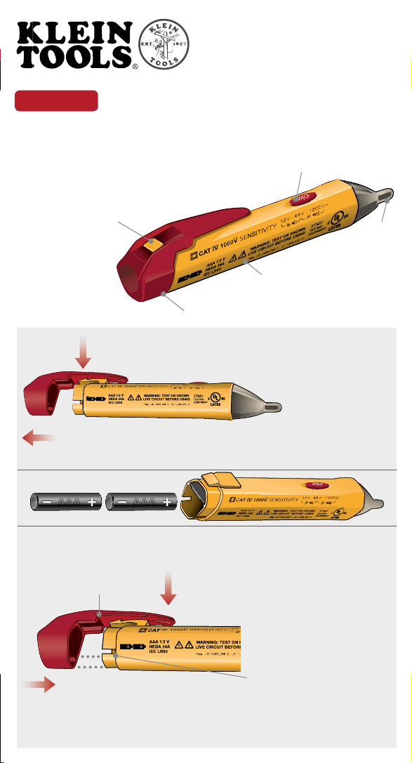
Locking tab / Lengüeta de fi jación /
Languette de verrouillage
Cap / Tapa / Capuchon
Power button /
Botón de alimentación /
Bouton de mise sous
tension
Body / Cuerpo / Corps
Fig. 1
Probe /
Conductor
de prueba /
Sonde
Fig. 2
While pushing down on tab, slide cap off body.
Mientras empuja hacia abajo sobre la lengüeta, deslice la tapa hasta separarla del cuerpo.
Faites glisser le capuchon de façon à le détacher du corps de l’appareil tout en appuyant sur la languette.
Fig. 3
Fig. 4
Align locking tab with cap.
Alinee la lengüeta de
fi jación con la tapa.
Alignez la languette de
verrouillage avec le capuchon.
Slide cap onto body.
Deslice la tapa sobre el cuerpo.
Faites glisser le capuchon sur le corps de l’appareil.
Gently push down on locking tab.
Empuje suavemente hacia abajo sobre la lengüeta de fi jación.
Appuyez doucement sur la languette de verrouillage.
AAAAAA
Hold pocket-clip on cap close to tester body while
sliding cap onto tester.
Sujete la pinza para bolsillo ubicada en la tapa cerca del cuerpo
del probador mientras desliza la tapa sobre el probador.
Maintenez la pince pour la poche sur le capuchon à proximité
du corps de l’appareil de mesure pendant que vous faites
glisser le capuchon sur l’appareil de mesure.
Align channel tabs on cap with slots
on tester body (one on each side of
tester).
Alinee las lengüetas de canal ubicadas
en la tapa con las ranuras ubicadas en
el cuerpo del probador (una a cada lado
del probador).
Alignez les languettes à rainures sur le
capuchon avec les fentes sur le corps
de l’appareil de mesure (une de chaque
côté de l’appareil de mesure).
Page 2
ENGLISH
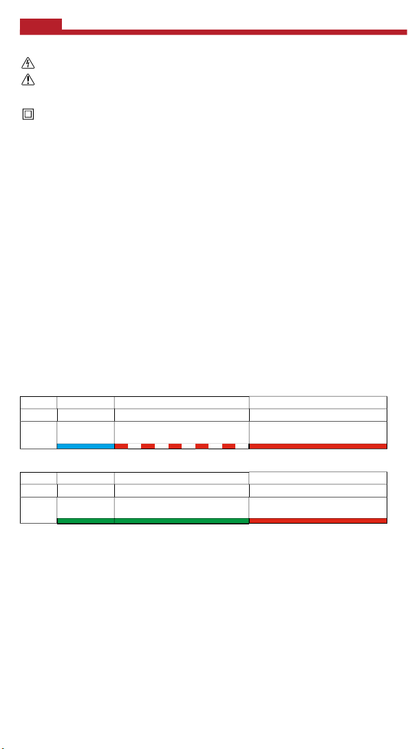
POWER-ON
12 TO 48 VOLTS AC
48 TO 1000 VOLTS AC
Audible
Visual
POWER-ON
12 TO 48 VOLTS AC
48 TO 1000 VOLTS AC
Audible
Visual
SYMBOLS ON TESTER:
Warning. Risk of electric shock.
Risk of danger. Important information: It is important that users of this tester read, understand, and follow all
warnings, cautions, safety information, and instructions in this manual before operating or servicing this tester. Failure
to follow instructions could result in death or serious injury.
Double Insulated.
CAT IV
Equipment is designed to protect against transients from the primary supply level.
(i.e. - electricity meter or overhead/ underground utility service).
OPERATING INSTRUCTIONS:
Modes of operation:
The NCVT-2 can operate as a dual range (NCVT-2 mode) or single range (NCVT-1 mode) tester. In NCVT-2 mode, the
tester will light a steady blue LED in the tip to indicate power-on and dual range mode. In NCVT-1 mode, the tester will
light a steady green LED in the tip to indicate power-on and single range mode.
Turn unit on:
Press and hold the power button for ½ second, then release. Listen for single-beep sound and watch for a steady green
or blue LED to illuminate in the tip of the tester. The tester is now activated and is operational. Test on known live circuit
to verify tester functionality. See Silent mode for additional power-on options.
Turn unit off:
Press and hold the power button for ½ second then release. Listen for a double-beep sound and watch the green or
blue LED turn off. The tester is now deactivated and is not operational.
System self-test:
T
he “power on” blue or green LED visually confi rms battery suffi ciency, system integrity, and operation/active mode.
Always test on known live circuit to verify tester functionality prior to use
Changing operation modes:
While the unit is powered on, press and hold the power button for 2 seconds. The unit will beep 3 times and the power-on LED will
switch from blue to green or green to blue. The tester will start in whichever mode it was last powered off in.
Checking for the presence of AC voltage:
Prior to use, test on known live circuit to verify tester functionality. Place tip of the tester near an AC voltage and refer
to the tables below for each mode:
NCVT-2 mode:
Single Beep Low-Pitched Pulsing Beeping Sound High-Pitched Continuous Beeping Sound
Steady Blue LED Blue LED Turns OFF and Red LED Blinks
(approximately 2-times per second).
.
Blue LED Turns OFF and Red LED
illuminates continuously.
NCVT-1 mode:
Single Beep No Sound High-Pitched Continuous Beeping Sound
Steady Green LED Steady Green LED Green LED Turns OFF and Red LED
In NCVT-2 mode, the tester will be more sensitive and will show voltage indication at a further distance away from a
high voltage source than in NCVT-1 mode. Use NCVT-1 mode in situations where you expect the voltage source will
be greater than 48V AC.
Low battery indication:
Scenario 1 – Powering on the tester: The “power on” LED in the tip of the tester changes from a steady green or blue to a
blinking green or blue and a series of beeping sounds is generated. The tester then turns off. The unit is now deactivated
and is not operational, the batteries require replacement. To replace the tester batteries refer to the Maintenance section
titled “Battery Replacement.”
Scenario 2 –
replace the tester batteries refer to the Maintenance section titled “Battery Replacement.”
Auto Power Off:
After 4 minutes of non-use, the tester automatically powers off to conserve battery life. Listen for a double-beep
sound and watch the “power on” LED turn off. The tester is now deactivated and is not operational.
Silent mode:
The tester can be operated with only visual indication of voltage. With the tester powered off, press and hold the
power button for 2 seconds then release.
Operating the tester: If the LED lights dim and the tone fades, the tester may require new batteries. To
illuminates continuously.
Page 3
MAINTENANCE:
CAUTION:
•
Do not attempt to repair this tester. It contains no serviceable parts.
Do not expose the product to extremes in temperature or high humidity.
WARNINGS:
•
It is important that users of this tester read, understand, and follow all warnings, cautions, safety information, and instructions
in this manual before operating or servicing this tester. Failure to follow instructions could result in death or serious injury.
Risk of electric shock and burn. Contact with live circuits could result in death or serious injury.
Use caution with voltages above 30V AC as a shock hazard may exist.
•
A blinking or steady red glow and an audible beep indicate voltage present. If no indication, voltage could still be present.
•
Before and after each use, verify operation by testing a known working circuit that is within the rating of this unit.
Never assume neutral or ground wires are de-energized.
The tester
WILL NOT
detect voltage if:
•
the wire is shielded.
•
the operator is not grounded or is otherwise isolated from an effective earth ground.
the voltage is DC.
The tester
MAY NOT
detect voltage if:
the user is not holding the tester.
•
the user is insulated from the tester with a glove or other materials.
•
the wire is partially buried or in a grounded metal conduit.
the tester is at a distance from the voltage source.
the fi eld created by the voltage source is being blocked, dampened, or otherwise interfered with.
the frequency of the voltage is not a perfect sine wave between 50 and 500Hz.
•
the tester is outside of operation conditions (listed in Specifi cations section).
Operation may be affected by differences in socket design and insulation thickness and type.
In bright light conditions, the LED visual indicators will be less visible.
Do not use if "power on" LED is not illuminated.
•
Do not use if tester appears damaged or if the tester is not operating properly. If in doubt, replace the tester.
•
Do not apply more than the rated voltage as marked on the tester (1000 volts AC).
Detection above 12V is specifi ed under "normal" conditions as specifi ed below. The tester may detect at a different threshold
at different conditions, or may not detect at all unless:
•
The tip of the tester is within 0.25" of an AC voltage source radiating unimpeded.
•
The user is holding the body of the tester with his or her bare hand.
The user is standing on or connected to earth ground.
The air humidity is nominal (50% relative humidity).
The tester is held still.
•
Always wear approved eye protection.
•
Comply with local and national safety requirements.
If this product is used in a manner not specifi ed by the manufacturer, protection provided by the product may
be affected.
Battery Replacement:
• Orient the tool/tester with the pocket-clip facing you.
• Gently depress the tab, Fig. 2, until you can slide the end-cap off the main body of the tester.
• Remove the batteries using caution to prevent damage or injury to the internal components.
• Replace with two 1.5V AAA or LR03 or NEDA 24A batteries.
• Place batteries into tester with the positive terminals facing the tip, Fig. 3.
• Carefully align and slide the end-cap to the body of the tester, Fig. 4. Push the cap
until it is fully seated (denoted by a clicking sound), Fig. 4.
• Note: Hold pocket-clip on cap close to tester body while sliding cap onto tester.
• Test on known live circuit to verify tester functionality.
Cleaning Tester:
• Tester contains sensitive electronic components; do not submerse in liquid.
• Do not use alcohol, ammonia or cleaners containing solvents to clean tester.
• Gently wipe the tester with Klein Kleaners
cleaning solution.
• Make sure the tester is completely dry prior to operation.
®
(CAT. # 51425 or 51426), a damp cloth or a cloth containing a mild
DISPOSAL:
• Do not throw depleted batteries away; please recycle properly.
• Do not throw tester away, please recycle properly.
• Please see www.epa.gov or www.erecycle.org for additional information.
WARRANTY
Klein electronic test and measurement devices (and accessories), manufactured and sold for commercial or industrial uses, are
warranted to be free from defects in materials and workmanship for two years from the date of purchase (unless otherwise noted
on the product packaging). THERE ARE NO IMPLIED WARRANTIES OF MERCHANTIBILITY OR FITNESS. At its option, Klein
will repair or replace, or refund the purchase price of, any product which fails to conform to this warranty under normal use and
service. In no event shall Klein be liable for incidental or consequential damage. This warranty does not apply to batteries.
Page 4

SPECIFICATIONS:
CAT
IV
Advertencia. Riesgo de descargas eléctricas.
VOLTAGE RANGE: 12-1000 Volts AC
TESTER TYPE: Non-Contact Voltage Detector
UL CERTIFICATION
E321008 3TMV
FREQUENCY RANGE:
50-500Hz
STANDARDS:
UL 61010-1 2nd edition, CAN/CSA C22.2 No.
61010-1-04, EN 61010-1 2nd edition, IEC
61010-1:2001 2
(IEC61010-1 MOD)
CAT IV RATED
DOUBLE INSULATED
POWER ON INDICATOR AND ILLUMINATOR:
Visual: High Intensity Green/Blue LED
POWER OFF & AUTO POWER OFF:
Visual: High Intensity Green LED Blinks
Audible: Double Beeping Sound
LOW BATTERY INDICATORS:
Visual: Green/Blue LED Blinks
Audible: Series of Beeping Sounds
nd
edition, ISA-82.02.01
VOLTAGE DETECTION INDICATORS:
12 VOLTS TO 48 VOLTS:
Visual: High Intensity Blinking Red LED
Audible: Low Pitched, Pulsing Beeping Sound
48 VOLTS TO 1000 VOLTS
Visual: High Intensity Continuously
Illuminated Red LED
Audible: High Pitched, Continuous
Beeping Sound
OPERATING CONDITIONS:
Temperature: 32° to 104° F (0° to 40° C)
Relative Humidity: <80%
Altitude: Up to 6,562 feet (2,000 meters) maximum
Environment: Indoor Use
STORAGE CONDITIONS:
Temperature: 32° to 104° F (0° to 40° C)
Relative Humidity: <80%
Altitude: Up to 6,562 feet (2,000 meters) maximum
Environment: Indoor
POLLUTION DEGREE: 2
Two 1.5 volt AAA or IEC LR03 or NEDA 24A
BATTERIES:
PATENTS: US D583,266 S
DISPOSAL: DO NOT THROW IN TRASH;
PLEASE RECYCLE.
ESPAÑOL
SÍMBOLOS UBICADOS EN EL PROBADOR:
Riesgo de peligro. Información importante: Es importante que los usuarios de este probador lean, entiendan y sigan
todas las advertencias, precauciones, información de seguridad e instrucciones contenidas en este manual antes de
utilizar el probador o hacerle servicio de mantenimiento. Si no se siguen estas instrucciones, el resultado podría ser
muerte o lesiones graves.
Con aislamiento doble.
CAT IV
El equipo está diseñado para proteger contra corrientes transitorias procedentes del nivel de alimentación primario (es decir,
contador de electricidad o servicio público elevado / subterráneo).
INSTRUCCIONES DE USO:
Modos de operación:
El NCVT-2 puede funcionar como un probador de intervalo dual (modo NCVT-2) o de intervalo sencillo (modo
NCVT-1). En el modo NCVT-2, el probador encenderá una luz LED azul constante en la punta para indicar que está
encendido y en el modo de intervalo dual. En el modo NCVT-1, el probador encenderá una luz LED verde constante en
la punta para indicar que está encendido y en el modo de intervalo sencillo.
Encienda la unidad:
Presione y mantenga presionado el botón de alimentación durante ½ segundo y luego suéltelo. Escuche hasta que
oiga un pitido único y espere hasta que se encienda una luz LED verde o azul constante en la punta del probador. Una
vez hecho esto, el probador estará activado y operativo.
Haga una prueba en un circuito con corriente conocido para verifi car la funcionalidad del probador. Consulte el Modo
silencioso para conocer las opciones de encendido adicionales.
Apague la unidad:
Presione y mantenga presionado el botón de alimentación durante ½ segundo y luego suéltelo. Escuche hasta que
oiga un pitido doble y espere hasta que la luz LED verde o azul se apague. Después de esto, el probador estará
desactivado y no estará operativo.
Page 5

ENCENDIDO
12 A 48 V CA
48 A 1000 V CA
Audible
Visual
POWER-ON
12 A 48 V CA
48 A 1000 V CA
Audible
Visual
ESPAÑOL
Autocomprobación del sistema:
La luz LED azul o verde de “encendido” confi rma la sufi ciencia de las pilas, la integridad del sistema y el modo de
operación/activo. Haga siempre una prueba en un circuito conocido para verifi car la funcionalidad del probador antes
de utilizarlo.
Cambio de modos de operación:
Mientras la unidad está encendida, presione y mantenga presionado el botón de alimentación durante 2 segundos. La
unidad pitará 3 veces y la luz LED de encendido cambiará de azul a verde o de verde a azul. El probador comenzará a
funcionar en el modo en el que se haya apagado la última vez.
Comprobación de la presencia de tensión de CA:
Antes de utilizar el probador, haga una prueba en un circuito con corriente conocido para verifi car la funcionalidad del
probador. Coloque la punta del probador cerca de una tensión de CA y consulte las tablas que aparecen más adelante
para cada modo.
Modo NCVT-2:
Pitido único Pitido pulsante de baja frecuencia Pitido continuo de alta frecuencia
Luz LED azul
constante
Modo NCVT-1:
Pitido único Sin sonido Pitido continuo de alta frecuencia
Luz LED verde
En el modo NCVT-2, el probador será más sensible y mostrará una indicación de tensión a una distancia mayor de
una fuente de alta tensión que en el modo NCVT-1. Utilice el modo NCVT-1 en situaciones en las que espere que la
fuente de tensión sea mayor de 48 V CA.
Indicación de pilas bajas:
Situación 1: Encendido del probador: La luz LED de “encendido” ubicada en la punta del probador cambia de un verde o
azul constante a un verde o azul parpadeante y se genera una serie de pitidos. Luego, el probador se apaga. Después de
esto, la unidad estará desactivada y no estará operativa, y será necesario reemplazar las pilas. Para reemplazar las pilas
del probador, consulte la sección de Mantenimiento titulada “Reemplazo de las pilas”.
Situación 2: Utilización del probador: Si las luces LED se atenúan y el tono se debilita, es posible que el probador necesite
pilas nuevas.
Para reemplazar las pilas del probador, consulte la sección de Mantenimiento titulada “Reemplazo de las pilas”.
Autoapagado:
Después de 4 minutos sin utilizarse, el probador se apaga automáticamente para prolongar la vida útil de las pilas.
Escuche hasta que oiga un pitido doble y espere hasta que la luz LED de “encendido” se apague. Después de eso, el
probador estará desactivado y no estará operativo.
Modo silencioso:
El probador se puede utilizar con indicación visual de tensión solamente. Con el probador apagado, presione y
mantenga presionado el botón de alimentación durante 2 segundos y luego suéltelo.
constante
MANTENIMIENTO:
Reemplazo de las pilas:
• Oriente la herramienta/probador con la pinza para bolsillo orientada hacia usted.
• Presione suavemente la lengüeta, Fig. 2, hasta que pueda deslizar la tapa de extremo y separarla del cuerpo
principal del probador.
• Retire las pilas, teniendo cuidado para prevenir daños o desperfectos a los componentes internos.
• Reemplace las pilas con dos pilas AAA de 1,5 V o LR03 o NEDA 24A.
• Coloque las pilas en el probador con los terminales positivos orientados hacia la punta, Fig. 3.
• Alinee y deslice cuidadosamente la tapa de extremo hasta el cuerpo del probador, Fig. 4. Empuje la tapa hasta que
esté completamente asentada (lo cual es indicado por un sonido tipo clic), Fig. 4.
• Nota: Sujete la pinza para bolsillo, ubicada en la tapa, cerca del cuerpo del probador mientras desliza la tapa sobre
el probador.
• Haga una prueba en un circuito con corriente conocido para verifi car la funcionalidad del probador.
Limpieza del probador:
• El probador contiene componentes electrónicos sensibles; no lo sumerja en ningún líquido.
• No use alcohol, amoníaco ni limpiadores que contengan solventes para limpiar el probador.
• Limpie suavemente el probador con limpiadores Klein Kleaners® (No. de CAT. 51425 ó 51426), un paño húmedo
o un paño que contenga una solución limpiadora suave.
• Asegúrese de que el probador esté completamente seco antes de utilizarlo.
La luz LED azul se apaga y la luz LED roja parpadea
(aproximadamente 2 veces por segundo).
Luz LED verde constante La luz LED verde se apaga y la luz LED
La luz LED azul se apaga y la luz LED roja
se enciende continuamente.
roja se enciende continuamente.
Page 6

ELIMINACIÓN:
PRECAUCIÓN:
•
No intente reparar este probador / herramienta. No contiene piezas reemplazables ni reparables.
No exponga el producto a extremos de temperatura o alta humedad.
ADVERTENCIAS:
Es importante que los usuarios de este probador lean, entiendan y sigan todas las advertencias, precauciones, información
de seguridad e instrucciones contenidas en este manual antes de utilizar el probador o hacer servicio de mantenimiento del
mismo. Si no se siguen las instrucciones, el resultado podría ser la muerte o lesiones graves.
Riesgo de descargas eléctricas y quemaduras. El contacto con circuitos con corriente podría causar la muerte o lesiones
graves.
Tenga precaución con las tensiones por encima de 30 V CA, ya que podría existir un peligro de descargas eléctricas.
Un brillo rojo parpadeante o constante y un pitido audible indican la presencia de tensión. Si no hay indicación, aún podría
haber tensión presente.
Antes y después de cada uso, verifi que el funcionamiento haciendo una prueba en un circuito que funcione conocido y que
esté dentro de la capacidad nominal de esta unidad.
No suponga nunca que los alambres neutro o de toma de tierra están sin tensión.
El probador
NO
detectará tensión si:
el alambre está blindado.
•
el operador no está conectado a tierra o está aislado de alguna manera de una toma de tierra efectiva.
la tensión es de CC.
PUEDE QUE
el probador
NO
detecte tensión si:
el usuario no está sosteniendo el probador.
el usuario está aislado del probador con un guante u otros materiales.
el alambre está enterrado parcialmente o en un conducto metálico conectado a tierra.
el probador está a una distancia de la fuente de tensión.
el campo creado por la fuente de tensión está siendo bloqueado, amortiguado o sometido a
interferencia de alguna otra manera.
la frecuencia de la tensión no es una onda sinusoidal perfecta entre 50 y 500 Hz.
el probador está fuera de las condiciones de funcionamiento (indicadas en la sección Especifi caciones)
El funcionamiento puede ser afectado por diferencias en el diseño del receptáculo y el grosor y el tipo de aislamiento
En condiciones de luz brillante, los indicadores visuales de luz LED serán menos visibles.
No utilice la unidad si la luz LED de "encendido" no está iluminada.
No utilice el probador si parece estar dañado o si no está funcionando apropiadamente. Si tiene dudas, reemplace el
probador.
No aplique una tensión nominal mayor que la marcada en el probador (1000 V CA).
La detección por encima de 12 V está especifi cada bajo condiciones "normales" tal y como se indica más adelante. Puede
que el probador detecte en un umbral diferente en condiciones distintas, o puede que no detecte absolutamente nada
a
menos que
La punta del probador está dentro de 0.25 pulgadas de una fuente de tensión de CA que irradia sin impedimento
El usuario está sosteniendo el cuerpo del probador con la mano desnuda.
El usuario está ubicado sobre una toma de tierra o conectado a ella.
La humedad del aire es nominal (humedad relativa del 50%).
El probador está siendo sostenido en posición fi ja.
Use siempre protección visual aprobada.
Cumpla con los requisitos de seguridad locales y nacionales.
Si este producto se utiliza de alguna manera no especifi cada por el fabricante, la protección provista por el producto
podría resultar afectada.
• No tire las pilas agotadas; sírvase reciclarlas apropiadamente.
• No tire el probador, sírvase reciclarlo apropiadamente.
• Sírvase visitar www.epa.gov o www.erecycle.org para obtener información adicional.
GARANTÍA
Se garantiza que los dispositivos electrónicos (y accesorios) de prueba y medición de Klein, fabricados y vendidos para usos
comerciales o industriales, estarán libres de defectos de materiales y fabricación durante dos años a partir de la fecha de compra
(a menos que se indique otra cosa en el embalaje del producto). NO HAY GARANTÍAS IMPLÍCITAS DE COMERCIABILIDAD O
IDONEIDAD. A su propia opción, Klein reparará, reemplazará o reembolsará el precio de compra de cualquier producto que no
cumpla con esta garantía bajo uso y servicio normales. Klein no será responsable en ningún caso por daños incidentales o
emergentes. Esta garantía no se aplica a las pilas.
Page 7

Avertissement. Risque de choc électrique.
CAT
ESPECIFICACIONES:
INTERVALO DE TENSIÓN: 12-1000 V CA
TIPO DE PROBADOR: Detector de
tensión sin contactos
GAMA DE FRECUENCIA:
50-500Hz
ESTÁNDARES:
UL 61010-1 2
61010-1-04, EN 61010-1 2
IEC 61010-1:2001 2
ISA-82.02.01 (IEC 61010-1 MOD)
CALIFICADO
CAT IT.
CON AISLAMIENTO DOBLE
INDICADOR DE ENCENDIDO
E ILUMINADOR:
Visual: LED verde de alta intensidad
APAGADO Y APAGADO AUTOMÁTICO:
Visual: El LED verde de alta intensidad
Audible: Sonido de doble pitido
INDICADORES DE PILAS BAJAS:
Visual: El LED verde de alta intensidad parpadea
Audible: Series de sonido en forma de pitido
CONDICIONES DE FUNCIONAMIENTO:
Temperatura: 32 a 104 °F (0 a 40 °C)
Humedad relativa: < 80%
Altitud: Hasta 6.562 pies (2.000 metros)
da
edición, CAN/CSA C22.2 No.
da
da
edición,
se apaga
Entorno: Uso en interiores
máximo
edición,
CERTIFICACIÓN UL:
E321008 3TMV
INDICADORES DE DETECCIÓN DE TENSIÓN:
12 V A 48 V:
Visual: LED rojo de alta intensidad
parpadeante
Audible: Sonido en forma de pitido
pulsante de baja frecuencia
48 V A 1000 V:
Visual: LED rojo de alta intensidad
iluminado continuamente
Audible: Sonido de pitido continuo
de alta frecuencia
CONDICIONES DE
ALMACENAMIENTO:
Temperatura: 32 a 104 °F(0 a 40 °C)
Humedad relativa: < 80%
Altitud: Hasta 6.562 pies
(2.000 metros) máximo
Entorno: Interiores
GRADO DE POLUCIÓN: 2
PILAS: Dos pilas AAA de 1,5 V o
IEC LR03 ó NEDA 24A
US D583,266 S,
PATENTES:
US 7,208,932 B1
ELIMINACIÓN: NO TIRE LA UNIDAD
A LA BASURA; POR
FAVOR, RECÍCLELA.
LE FRANÇAIS
SYMBOLES SUR L’APPAREIL DE MESURE :
Risque de danger. Informations importantes : Il est important que les utilisateurs de ce détecteur lisent,
comprennent et respectent tous les avertissements, mises en garde, informations relatives à la sécurité et
instructions de ce manuel avant de mettre ce détecteur en marche ou de la réparer. Le non-respect de ces
instructions pourrait causer la mort ou une blessure grave.
Double isolation.
CAT IV Cet équipement est conçu pour protéger contre les ondes transitoires du niveau d’alimentation électrique
primaire. (c. à d. - compteur électrique ou service utilitaire par connexions aériennes/souterraines).
MODE D'EMPLOI
Modes de fonctionnement :
Le testeur NCVT-2 peut fonctionner comme testeur à double gamme (mode NCVT-2) ou à gamme unique (mode
NCVT-1). Dans le mode NCVT-2, un voyant à DEL bleu s’allumera sur la pointe du testeur et restera continuellement
allumé pour indiquer que le testeur est sous tension et dans le mode à double gamme. Dans le mode NCVT-1, un
voyant à DEL vert s’allumera sur la pointe du testeur et restera continuellement allumé pour indiquer que le testeur
est sous tension et dans le mode à gamme unique.
Mise de l’appareil sous tension :
Appuyez sur le bouton de mise sous tension pendant 1/2 seconde, puis relâchez-le. Vous entendrez un bip unique et
vous verrez un voyant à DEL vert ou bleu s’allumer à la pointe du testeur. Le testeur est activé et opérationnel.
Testez l’appareil sur un circuit que vous savez être sous tension pour en vérifi er la fonctionnalité. Voir Mode silencieux
pour plus d’options sur la mise sous tension.
Page 8

SOUS TENSION
12 À 48 VOLTS C.A.
48 À 1 000 VOLTS C.A.
Audible
Visuel
SOUS TENSION
12 À 48 VOLTS C.A.
48 À 1 000 VOLTS C.A.
Audible
Visuel
LE FRANÇAIS
Mise de l’appareil hors tension :
Appuyez sur le bouton de mise sous tension pendant 1/2 seconde, puis relâchez-le. Attendez que retentisse un double
bip et que le voyant à DEL vert ou bleu s'éteigne. Le testeur est maintenant désactivé et n'est pas opérationnel.
Test automatique du système :
Le voyant à DEL bleu ou vert indiquant que l'appareil est sous tension confi rme un niveau de charge adéquat,
l'intégrité du système et le mode actif/opérationnel.
Testez toujours le testeur sur un circuit que vous savez être sous tension pour en vérifi er la fonctionnalité avant
l'emploi.
Changement du mode de fonctionnement :
Pendant que l’appareil est sous tension, appuyez sur le bouton de mise sous tension pendant 2 secondes. L’appareil
émettra trois bips et le voyant à DEL de mise sous tension passera du bleu au vert ou du vert au bleu. L’appareil de
test se mettra en marche dans le mode de test dans lequel il était quand il a été mis hors tension.
Détection de la présence du courant secteur :
Testez le testeur sur un circuit que vous savez être sous tension pour en vérifi er la fonctionnalité avant l'emploi.
Placez la pointe du testeur près d’une source de tension c.a. et référez-vous aux tableaux ci-dessous pour chaque
mode.
Mode NCVT-2 :
Bip unique Bip à pulsation de tonalité grave Bip continu à tonalité aiguë
Voyant à DEL bleu allumé
continuellement
Mode NCVT-1 :
Bip unique Pas de tonalité Bip continu à tonalité aiguë
Voyant à DEL vert allumé
continuellement
Dans le mode NCVT-2, le testeur sera plus sensible et montrera une indication de tension à une distance plus grande
d'une source de haute tension que dans le mode NCVT-1. Utilisez le mode NCVT-1 dans des situations où vous
pensez que la source de tension sera supérieure à 48 V c.a.
Indication de décharge partielle des piles :
Scénario 1 – Mise du testeur sous tension : Le voyant à DEL indiquant que l’appareil est sous tension sur la pointe du
testeur passe de vert ou bleu constant à vert ou bleu clignotant, et des bips répétés retentissent. Le testeur s'éteint alors.
L'appareil est maintenant désactivé et n'est pas opérationnel ; il faut remplacer les piles. Pour remplacer les piles du
testeur, référez-vous à la section Maintenance intitulée « Remplacement des piles ».
Scénario 2 – Utilisation du testeur : Si l'éclairage du voyant à DEL est faible et si la tonalité s'estompe, ceci peut signifi er
que le testeur a besoin de nouvelles piles.
Pour remplacer les piles du testeur, référez-vous à la section Maintenance intitulée « Remplacement des piles ».
Mise hors tension automatiquement
Au bout de 4 minutes sans utilisation, le testeur se met hors tension automatiquement pour conserver la charge
des piles. Attendez que retentisse un double bip et que le voyant à DEL indiquant que l'appareil est sous tension
s'éteigne. Le testeur est maintenant désactivé et n'est pas opérationnel.
Mode silencieux :
Le testeur peut être utilisé avec seulement l’indication visuelle de tension. Avec le testeur hors tension, appuyez sur
le bouton de mise sous tension pendant 2 secondes, puis relâchez-le.
MAINTENANCE :
Remplacement des piles :
• Orientez l'outil/le testeur de façon que la pince de poche soit face à vous.
• Appuyez doucement sur l’onglet, Fig. 2, jusqu’à ce que vous puissiez faire glisser le capuchon pour le détacher
du corps du testeur.
• Retirez les piles en faisant attention de ne pas endommager ou abîmer les composants internes.
• Remplacez les deux piles de 1,5 V AAA, LR03 ou NEDA de 24 A.
• Placez les piles dans le testeur avec les bornes positives orientées vers la pointe, comme le montre la Figure 3.
Alignez soigneusement le capuchon et faites-le glisser sur le corps du testeur Fig. 4. Appuyez sur le capuchon
jusqu'à ce qu'il soit bien en place (vous entendrez un déclic pour le confi rmer), comme le montre la Figure 4.
Le voyant à DEL bleu s’éteint et le voyant à DEL
rouge clignote (à peu près deux fois par seconde).
Voyant à DEL vert allumé continuellement Le voyant à DEL vert s’éteint et le voyant à
Le voyant à DEL bleu s’éteint et le voyant
à DEL rouge s'allume continuellement.
DEL rouge s'allume continuellement.
Page 9

AVERTISSEMENTS :
Il est important que les utilisateurs de ce testeur lisent, comprennent et respectent tous les avertissements, mises en garde,
informations relatives à la sécurité et instructions de ce manuel avant de mettre ce testeur en marche ou de la réparer.
Le non-respect de ces instructions pourrait causer la mort ou une blessure grave.
•
Risques de choc électrique et de brûlure. Un contact avec des circuits sous tension pourrait causer la mort ou une
blessure grave.
Prenez des précautions avec des tensions de plus de 30 V c.a., car il existe alors un risque de choc.
Un voyant rouge clignotant ou constant et un bip audible indiquent la présence de tension. Même en l'absence d'indication,
une tension pourrait être présente.
•
Vérifi ez le fonctionnement avant chaque emploi en testant un circuit que vous savez être en état de fonctionnement qui est
compris dans les tolérances de cet appareil.
Ne supposez jamais que des fi ls neutres ou mis à la terre ne sont pas sous tension.
Le testeur
NE DÉTECTERA PAS
de tension si:
•
le fi l est blindé.
l’opérateur n’est pas mis à la terre ou est isolé d’une quelconque autre manière d’une terre ou masse réelle.
la tension est une tension continue (c.c.).
Le testeur
NE DÉTECTERA PEUT-ÊTRE PAS
de tension si:
l’utilisateur ne tient pas le testeur.
•
l’utilisateur est isolé du testeur par un gant ou un autre matériau.
le fi l est partiellement enterré ou est dans un conduit en métal mis à la terre.
le testeur est à une certaine distance de la source de tension.
le champ créé par la source de tension est bloqué, humidifi é ou altéré de toute autre façon.
•
la fréquence de la tension n'est pas une onde sinusoïdale parfaite entre 50 et 500 Hz.
le testeur est en dehors des conditions de fonctionnement (indiquées dans la section Spécifi cations).Le fonctionnement
peut être affecté par des différences de conception des prises de courant ainsi que d'épaisseur et de type d'isolant.
Dans des conditions de lumière vive, les indicateurs visuels à DEL seront moins visibles.
N'utilisez pas l’appareil si le voyant à DEL "puissance sur" n'est pas allumé.
N'utilisez pas l’appareil s'il semble endommagé ou s'il ne fonctionne pas correctement. Remplacez le testeur en cas de doute.
N'appliquez pas plus que la tension nominale indiquée sur le testeur (1 000 V c.a.).
La détection en dessus de 12 V est indiquée dans des conditions « normales » comme indiqué ci-dessous. L’appareil peut
détecter à un seuil différent dans des conditions différentes, ou il peut ne rien détecter du tout
à moins que
La pointe du testeur est à 6 mm maximum (0,25 po) de distance d’une source de tension alternative rayonnant
sans obstacle.
L’utilisateur tient le corps du testeur avec sa main nue.
L’utilisateur se tient sur une terre ou une masse, ou il y est connecté.
L’humidité de l’air est nominale (50 % d’humidité relative).
•
Le testeur est tenu immobile.
Toujours porter des équipements agréés de protection des yeux.
Respecter les règlements de sécurité locaux et nationaux.
Si ce produit est utilisé d'une manière non autorisée par le fabricant, la protection fournie par le produit risquerait
d'en être affectée.
• Remarque : Maintenez la pince de poche sur le capuchon près du corps du testeur pendant que vous faites
MISE EN GARDE :
•
Ne tentez pas de réparer vous-même ce détecteur/cet outil. Il ne contient
pas de pièces pouvant être réparées par l’utilisateur.
N’exposez pas le produit à des extrêmes de température ou à une humidité élevée.
glisser le capuchon sur le testeur.
• Testez sur un circuit que vous savez être sous tension pour vérifi er la fonctionnalité du testeur.
Nettoyage du testeur :
• Le testeur contient des composants électroniques sensibles ; ne l'immergez pas dans du liquide.
• N'utilisez pas d'alcool, d'ammoniac ou de produits de nettoyage contenant des solvants pour nettoyer le testeur.
• Essuyez doucement le testeur avec le produit Klein Kleaners® (CAT. N° 51425 ou 51426), un chiffon humide ou
un chiffon contenant une solution de nettoyage douce.
• Assurez-vous que le testeur est complètement sec avant de vous en servir.
MISE AU REBUT :
• Ne jetez pas les piles complètement déchargées ; veuillez les recycler de façon appropriée.
• Ne jetez pas le testeur ; veuillez le recycler de façon appropriée.
• Veuillez aller à www.epa.gov ou www.erecycle.org pour plus d'informations.
GARANTIE
Les appareils électroniques de mesure et de test (et accessoires) Klein fabriqués et vendus pour des emplois commerciaux et
industriels sont garantis ne comporter aucun défaut de matériau ou vice de fabrication pendant deux ans à compter de la date
de l’achat (sauf indication contraire sur l’emballage du produit). AUCUNE GARANTIE IMPLICITE DE QUALITÉ MARCHANDE OU
D’ADÉQUATION À UN BUT PARTICULIER N’EST OFFERTE. À son choix, Klein réparera ou remplacera tout produit qui ne serait
pas conforme à cette garantie dans des conditions normales d’utilisation et de service, ou en remboursera le prix d’achat. Klein
n’assumera en aucun cas de responsabilité pour des dommages indirects ou secondaires. Cette garantie ne s’applique pas
aux piles..
Page 10

SPÉCIFICATIONS :
CAT
IV
PLAGE DE TENSIONS : 12 - 1000 V c.a.
TYPE D’APPAREIL DE MESURE :
Détecteur de tension sans contact
CERTIFICATION UL :
E321008 3TMV
PLAGE DE FRÉQUENCE : 50-500 Hz
NORMES :
UL 61010-1 2
61010-1-04, EN 61010-1 2
61010-1:2001 2
(IEC 61010-1 MOD)
COTE
CAT IV.
e
édition, CANCSA C22.2 N°
e
édition, IEC
e
édition, ISA-82.02.01
DOUBLE ISOLATION.
INDICATEUR DE CIRCUIT SOUS
TENSION AVEC ILLUMINATION :
Visuel : DEL verte haute intensité
MISE HORS TENSION & MISE HORS
TENSION AUTOMATIQUE :
Visuel: DEL verte haute intensité
s’ éteignant
Audible : Double bip sonore
INDICATEUR DE DÉCHARGE
PARTIELLE DES PILES :
Visuel : DEL verte haute intensité clignotant
Audible : Série de bips sonores
INDICATEURS DE DÉTECTION DE TENSION :
12 VOLTS À 48 VOLTS :
Visuel : DEL rouge haute intensité clignotant
Audible : Bip sonore pulsé à tonalité grave
48 VOLTS À 1 000 VOLTS :
Visuel :
Audible : Bip sonore continu à tonalité aiguë
NOTICE D’UTILISATION :
Température : 32° à 104° F(0° à 40° C)
Humidité relative : <80 %
Altitude : Jusqu'à 6,562 pi
CONDITIONS D’ENTREPOSAGE :
Température : 32° à 104° F (0° à 40° C)
Humidité relative : <80 %
Altitude : Jusqu'à 6,562 pi (2 000 mètres) maximum
DEGRÉ DE POLLUTION : 2
PILES : Deux piles AAA de 1,5 V
BREVETS : US D583,266 S
MISE AU REBUT :
LES ORDURES ;
VEUILLEZ RECYCLER.
DEL rouge haute intensité
constamment allumée
(2 000 mètres) maximum
Environnement : Emploi intérieur
Environnement : intérieur
ou IEC LR03 ou NEDA 24A
US 7,208,932 B1
NE JETEZ PAS DANS
 Loading...