

ENGLISH
INSTRUCTION MANUAL
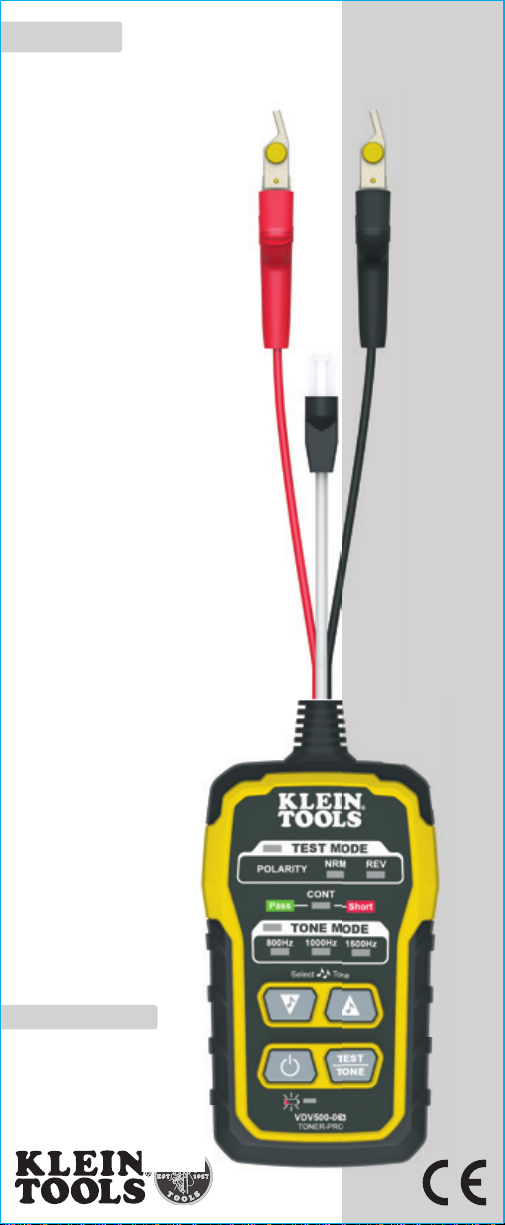
Toner-Pro
Tone Generator
• TRACE INDIVIDUAL
OR PAIRED WIRES*
• TEST RJ11, RJ12,
AND RJ45 JACKS*
• DETECTS
CONTINUITY AND
POLARITY
• 5 DISTINCT TONES
(3 CONSTANT,
2 ALTERNATING)
• EASY-TOUNDERSTAND
STATUS LEDs
* When used with VDV500-123 Probe-Pro
VDV500-063
DEUTSCH Seite 9
1
ENGLISH
GENERAL SPECIFICATIONS
The Klein Tools VDV500-063 Toner-Pro is a professional-series tone
generator for wire identification, wire tracing and wire pair identification.
It features several tone frequencies and strong power output for tracing
wires.
Operating Altitude: 6562 ft. (2000 m) maximum
•
Relative Humidity: 10% – 90% non-condensing
•
Operating Temp: 14° to 122°F (-10° to 50°C)
•
Storage Temp: -4° to 140°F (-20° to 60°C)
•
Dimensions: 2.5" x 5" x 1" (64 x 127 x 25 mm)
•
Weight: 7.4 oz. (210 g) including batteries
•
Battery Type: 4 x 1.5V AAA Alkaline
•
Battery Life: Active: 120 hours
•
Standby/Storage: 3 years
Auto-Power Off: After 60 minutes of inactivity
•
Tones: Constant: 800Hz, 1000Hz, 1500Hz
•
Alternating: 800Hz/1000Hz, 1000Hz/1500Hz
Tone Power: 8dBm
•
Continuity Indication: Less than 10kΩ
•
Voltage Protection: Test Mode: 60V
•
Tone Mode:
20V through external 600Ω
Specifications subject to change.
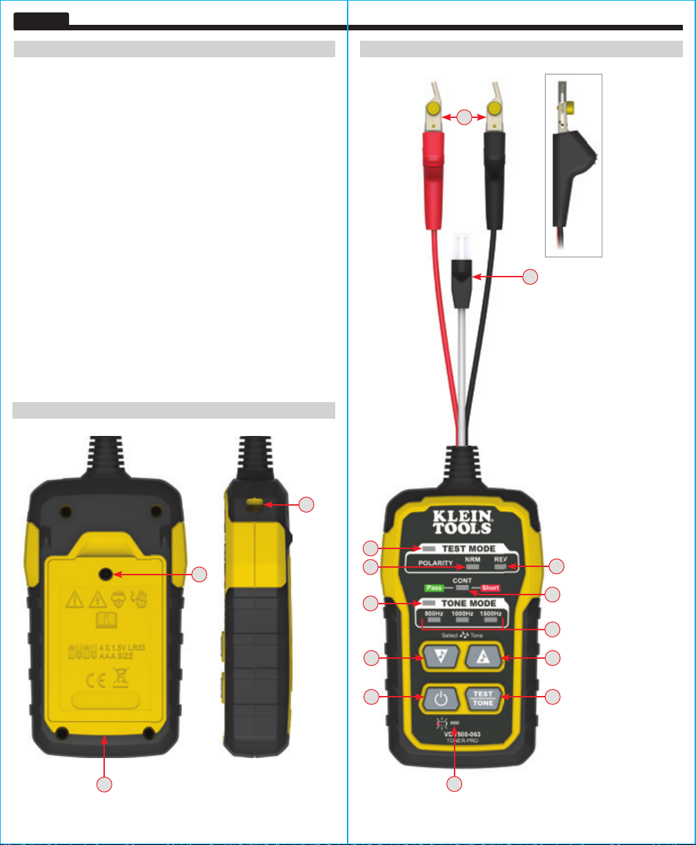
FEATURE DETAILS
T12
T16
T1
T2
T5
T7
T9
FEATURE DETAILS
T14
T13
T4
T6
T8
T10
T3
T1
TEST MODE Indicator
T2
"NRM" (Normal)
Polarity Indicator
T3
"REV" (Reverse)
Polarity Indicator
T4
"CONT" (Continuity)
Indicator
T5
TONE MODE
Indicator
T6
Tone Frequency
Indicators
T7
Tone Mode Down
selector button
T8
Tone Mode Up
selector button
T9
Power On/Off Button
T10
TEST/TONE Button
T11
Battery Status
Indicator
T12
Lanyard Slot
T13
RJ11 Test Plug
T14
ABN (Angled Bedof-Nails) Test Clips
T15
Battery Cover
T16
Battery Cover Screw
(#2 Phillips)
T15
2 3
T11

ENGLISH
WARNINGS
To ensure safe operations and service of the instruments, follow these
instructions. Failure to observe these warnings can result in re,
FIG. 1
electric shock, severe injury or death.
The Toner-Pro and Probe-Pro (sold seperately) are designed for use on extra-low
•
voltage cabling systems (less than 60 volts) for testing when NOT energized.
The maximum voltage across ABN Test Clips of the Toner-Pro is 60 volts in
•
Test mode, and 20 volts in Continuity mode. Connecting the Probe-Pro to live
mains AC power may damage it and pose a safety hazard for the user.
DO NOT use instruments if they are wet, as it could pose a shock hazard.
•
DO NOT use instruments if they are damaged in any way.
•
Turn off instruments and disconnect all ABN Test Clips before attempting to
•
replace batteries.
The battery door must be in place and secure before you operate the instrument.
•
DO NOT open the case, other than the battery compartment.
•
OPERATING INSTRUCTIONS
READ ALL INSTRUCTIONS BEFORE OPERATING AND RETAIN
INSTRUCTIONS FOR FUTURE REFERENCE
CONTINUITY TEST
The Toner-Pro transmits frequencies on non-energized wires only. When the
Toner-Pro is turned on, a continuity test will be performed to determine if the 2
wires to be traced are in close proximity to each other, without a conductive path
between them. The "CONT" Indicator T4 wIll illuminate green to indicate pass.
Attach the red and black ABN Test Clips
to the wires to be tested. If the
T14
resistance of the circuit is less than 10kΩ, the "CONT" Indicator T4 will illuminate
red and no toning can occur. If the "CONT" Indicator is illuminated green, a tone
can be generated and you may proceed.
SELECTING TONE FREQUENCY
The Toner-Pro defaults to the 800Hz frequency setting when powered on. Use
the Tone Mode Up T8 and Tone Mode Down T7 selector buttons to change the
frequency. The Tone Frequency Indicators T6 will display the frequency being
transmitted. If an alternating tone is selected, the two respective Tone Frequency
Indicators T6 will blink. Tones will cycle through the available frequencies in a
TRACING NON-PAIRED WIRES (FIG. 2)
1. Connect the Toner-Pro’s red ABN Test Clip
2. Connect the black ABN Test Clip
not in the same pair (connect to ground, if available). When tracing a shielded
cable, connect the red ABN Test Clip to the outer shield, and the black ABN Test
Clip to the center conductor or ground.
3. Turn Toner-Pro on by pressing the Power On/Off button T9.
4. Check the “CONT” Indicator T4. If illuminated green, you may proceed.
5. Turn on the Probe-Pro (sold seperately).
6. Select the preferred tone setting using the Tone Mode Up T8 or Tone Mode
Down T7 selector buttons.
7. At the far end of the cable, spread the wires at least 2" (51 mm) apart, if possible.
8. Use the Probe-Pro (sold seperately) to scan the cable’s wire pairs. Move the
Probe-Pro's tip slowly across the wires. The Probe-Pro’s volume will increase
as it approaches the toned wire.
continuous loop when a selector button is pressed repeatedly.
TRACING PAIRED WIRES (FIG. 1)
1. Connect the Toner-Pro’s red ABN Test Clip
pair to be traced. Connect the black ABN Test Clip
to one of the wires of the
T14
to the other wire to
T14
FIG. 2
be traced.
2. Turn Toner-Pro on by pressing the Power On/Off button T9.
3. Check the “CONT” Indicator T4. If illuminated green, you may proceed.
4. Select the preferred tone setting using the Tone Mode Up T8 and/or Tone
Mode Down T7 selector buttons.
5. Turn on the Probe-Pro (sold seperately).
6. At the far end of the cable, spread the wires apart at least 2" (51 mm), if possible.
7. Use the Probe-Pro (sold seperately) to scan the cable’s wire pairs. Move the
Probe-Pro's tip slowly across the wires. The Probe-Pro’s volume will increase
as it approaches the toned pair. When the Probe-Pro’s volume is high over
the first wire, low in the middle (between) the two wires, and high over the
second wire, you have located the pair of wires you are tracing. Use the
Volume Increase
and
Volume Decrease
buttons to adjust the volume.
OPERATING INSTRUCTIONS
VDV500-123
(sold seperately)
to the wire to be traced.
T14
to another wire in the cable, but preferably
T14
VDV500-123
(sold seperately)
2"
(51 mm)
2"
(51 mm)
4 5

ENGLISH
OPERATING INSTRUCTIONS
RJ11 / RJ12 / RJ45 TESTING
The Toner-Pro has an
RJ11 Test Plug
that can be used in place of the
T13
ABN clips to transmit the tone. The RJ11 plug works with RJ11, RJ12, or
RJ45 jacks. The red and black ABN contacts are replaced by the 2 center
conductors of the inserted plug, i.e. pins 2 and 3 for RJ11, pins 3 and 4 for
RJ12, and pins 4 and 5 for RJ45.
Use the Probe-Pro
(sold seperately)
to locate the toned wires at the far end of
the cable, as described in the TRACING PAIRED WIRES section.
POLARITY AND VOLTAGE PRESENCE TESTING
The Toner-Pro may be used to test the polarity and type of voltage present.
1. Press the
2. Press the
Power On/Off button
TEST/TONE Select button
will illuminate.
T1
3. Connect the
ABN Test Clips
T9 on the Toner-Pro.
button
T10
, or insert the
T14
. The "TEST MODE" indicator
RJ11 Test Plug
T13
.
4. Check the “CONT” Indicator T4. If illuminated green, you may proceed.
5. The
"NRM" (Normal) Polarity Indicator
Test Clip
proper orientation. The
is connected to the POTS (Plain Ol' Telephone Service) in the
T14
"REV" (Reverse) Polarity Indicator
T2 will illuminate if the red
ABN
T3 will illuminate
if the wires are reversed.
• The
"NRM" (Normal) Polarity Indicator
T2 will illuminate
when the black
ABN Test Clip detects higher voltage than the red ABN Test Clip.
• The
"REV" (Reverse) Polarity Indicator
T3 w
ill illuminate
when the red
ABN Test Clip detects higher voltage than the black ABN Test Clip.
• The
"NRM" (Normal) Polarity Indicator and "REV" (Reverse) Polarity
Indicator will both illuminate when
• When the
will illuminate on
RJ11 Test Plug
a correctly wired and powered POTS (Plain Ol'
AC voltage is present.
is used, the
"NRM" (Normal) Polarity Indicator
Telephone Service) phone jack.
NOTE: The POTS (Plain Ol' Telephone Service) color code convention
(black/positive, red/negative) is the opposite of the multimeter color
code convention (red/positive, black/negative).
MAINTENANCE
BATTERY REPLACEMENT
When the Low Battery Indicator
blinks, the batteries must be
T11
replaced.
1. Turn off instrument(s) before attempting to replace batteries.
2. Loosen screw
,
on battery cover
T16
.
T15
3. Remove and properly dispose of four 1.5V AAA batteries.
4. Install new batteries (note proper polarity).
5. Replace battery cover and fasten securely with screw.
To avoid risk of electric shock, do not operate while battery door
is removed.
CLEANING
Be sure equipment is turned off and wipe with a clean, dry lint-free
cloth.
Do not use abrasive cleaners or solvents.
STORAGE
Remove the batteries when equipment is not in use for a prolonged period
of time. Do not expose to high temperatures or humidity. After a period
of storage in extreme conditions exceeding the limits mentioned in the
GENERAL SPECIFICATIONS section, allow the equipment to return to
normal operating conditions before using.
WARRANTY
www.kleintools.com/warranty
DISPOSAL / RECYCLE
Do not place equipment and its accessories in the trash. Items must
be properly disposed of in accordance with local regulations. Please
see www.epa.gov or www.erecycle.org for additional information.
CUSTOMER SERVICE
KLEIN TOOLS, INC.
450 Bond Street
Lincolnshire, IL 60069
1-877-775-5346
6 7
customerservice@kleintools.com
www.kleintools.com

NOTES
8
1390302 - German

DEUTSCH
GEBRAUCHSANLEITUNG
Toner-Pro
Tongenerator
• ORTUNG VON
EINZELNEN
KABELN ODER
KABELPAAREN*
• PRÜFUNG VON
RJ11-, RJ12UND RJ45DATENBUCHSEN*
• ANZEIGEN VON
DURCHGANG UND
POLARITÄT
• 5 VERSCHIEDENE
TÖNE (
3 DAUERTÖNE,
2 ALTERNIERENDE
TÖNE)
• EINFACH ZU
IDENTIFIZIERENDE
STATUS-LEDs
* Bei Verwendung mit der
VDV500-123 Probe-Pro
VDV500-063
9

DEUTSCH
ALLGEMEINE TECHNISCHE DATEN
Bei diesem VDV500-063 Toner-Pro von Klein Tools handelt es sich
um einen professionellen Tongenerator zur Kabelidentifikation,
Kabelortung und Kabelpaaridentifikation. Das Gerät verfügt über mehrere
Tonfrequenzen und eine hohe Ausgangsleistung zur Ortung von Kabeln.
Betriebshöhe: max. 2000m (6562 Fuß)
•
Relative Luftfeuchtigkeit: 10 bis 90%, nicht kondensierend
•
Betriebstemperatur: -10 °C bis 50 °C (14 °F bis 122 °F)
•
Lagertemperatur: -20 °C bis 60 °C (-4 °F bis 140 °F)
•
Abmessungen: 64 x 127 x 25 mm (2,5 x 5 x 1Zoll)
•
Gewicht: 210 g (7,4 oz) einschließlich Batterien
•
Batterietyp: 4 x 1,5V AAA Alkalibatterien
•
Batterienutzungsdauer: Aktiver Betrieb: 120 Stunden
•
Standby/Lagerung: 3Jahre
Automatische Abschaltung: Nach 60 Minuten Inaktivität
•
Töne: Dauertöne: 800 Hz, 1.000 Hz, 1.500 Hz
•
Alternierende Töne: 800Hz/1.000Hz, 1.000Hz/1.500Hz
Tonleistung: 8dBm
•
Durchgangsanzeige: Weniger als 10kΩ
•
Spannungsschutz: Prüfmodus: 60 V
•
Tonmodus:
20Volt durch externen 600 Ω
Änderungen der technischen Daten vorbehalten.
FUNKTIONSDETAILS
T12
T16
T15
T1
T2
T5
T7
T9
FUNKTIONSDETAILS
T14
T11
T13
T1
„TEST MODE“(PRÜFMODUS)-Anzeige
T2
Anzeige für „NRM“
(normale) Polarität
T3
Anzeige für „REV“
(umgekehrte)
Polarität
T4
„CONT“(Durchgang)Anzeige
T5
„TONE MODE“(TONMODUS)-Anzeige
T6
Tonfrequenz-Anzeigen
T7
Auswahltaste für
„Tonmodus Abwärts“
T8
Auswahltaste für
„Tonmodus Aufwärts“
T9
Taste „On/Off“
(„Ein/Aus“)
T3
T10
Taste „TEST/TONE“
T4
(„TONPRÜFUNG“)
T11
BatteriestatusAnzeige
T6
T12
Schlitz für Trageschlaufe
T8
T13
RJ11-Teststecker
T14
ABN(Angled Bed of
T10
Nails)-Testclips
T15
Batterieabdeckung
T16
Schraube der
Batterieabdeckung
(Nr. 2 Phillips)
10 11

DEUTSCH
WARNUNGEN
BETRIEBSANLEITUNG
Beachten Sie die folgenden Anweisungen, um einen sicheren Betrieb und
eine sichere Wartung der Geräte zu gewährleisten. Bei Nichtbeachtung dieser
ABB. 1
Warnungen können Brände, Stromschläge und schwere bis lebensgefährliche
Verletzungen verursacht werden.
Toner-Pro and Probe-Pro (separat erhältlich) sind zum Testen von Kabelsystemen
•
mit Kleinspannungen (weniger als 60Volt) ausgelegt, wenn diese NICHT unter
Spannung stehen.
Die maximale Spannung der ABN-Testclips des Toner-Pro beträgt 60V im
•
Prüfmodus und 20V im Durchgangsmodus. Der Anschluss des Probe-Pro an
spannungsführende Wechselstromleitungen kann zur Beschädigung des Gerätes
führen und die Sicherheit des Benutzers gefährden.
VERWENDEN SIE DIE GERÄTE NICHT, wenn diese nass sind, da
•
Stromschlaggefahr besteht.
VERWENDEN SIE DIE GERÄTE NICHT, wenn diese in irgendeiner Weise
•
beschädigt sind.
Schalten Sie die Geräte ab und entfernen Sie alle ABN-Testclips, bevor Sie die
•
Batterien austauschen.
Die Batterieabdeckung muss vor dem Betrieb des Geräts an ihrem vorgesehenen
•
Platz sein und gesichert werden.
ÖFFNEN SIE DAS GEHÄUSE NICHT an anderen Stellen als dem Batteriefach.
•
BETRIEBSANLEITUNG
BITTE LESEN SIE VOR DEM BETRIEB DIE ANLEITUNG UND BEWAHREN SIE
DIESE ZUM SPÄTEREN NACHSCHLAGEN AUF.
DURCHGANGSPRÜFUNG
Der Toner-Pro übermittelt ausschließlich Frequenzen von nicht unter Spannung stehenden
Kabeln. Ist der Toner-Pro eingeschaltet, wird eine Durchgangsprüfung durchgeführt, um
festzustellen, ob die beiden zu ortenden Kabel ohne dazwischen liegende Leiterbahn nahe
beieinander positioniert sind. Die „CONT“(Durchgang)-Anzeige
um eine bestandene Prüfung anzuzeigen. Befestigen Sie die roten und schwarzen ABNTestclips
geringer als 10kΩ ist, leuchtet die „CONT“(Durchgang)-Anzeige
keine Tonortung durchgeführt werden. Leuchtet die „CONT“(Durchgang)-Anzeige grün,
kann ein Ton generiert werden und Sie können fortfahren.
AUSWAHL DER TONFREQUENZ
Der Toner-Pro ist beim Einschalten standardmäßig auf eine Frequenz von 800 Hz
eingestellt. Verwenden Sie die Auswahltasten für „Tonmodus Aufwärts“
„Tonmodus Abwärts“
zeigen die Frequenz an, die übermittelt wird. Bei Auswahl eines alternierenden Tons
blinken die beiden entsprechenden Tonfrequenz-Anzeigen
zwischen den verfügbaren Frequenzen in Dauerschleife, wenn eine Auswahltaste
mehrmals gedrückt wird.
ORTUNG VON KABELPAAREN (ABB. 1)
1. Verbinden Sie den roten ABN-Testclip des Toner-Pro
2. Schalten Sie den Toner-Pro durch Drücken der Taste „On/Off“ („Ein/Aus“)
3. Prüfen Sie die „CONT“(Durchgang)-Anzeige
4. Wählen Sie
5. Schalten Sie die Probe-Pro (separat erhältlich) ein.
6. Spreizen Sie die Kabel am hinteren Ende der Leitung, wenn möglich, mindestens
7. Nutzen Sie die Probe-Pro (separat erhältlich), um die Kabelpaare der Leitung zu
12 13
an den zu überprüfenden Kabeln. Wenn der Widerstand des Stromkreises
T14
, um die Frequenz zu ändern. Die Tonfrequenz-Anzeigen
T7
ortenden Kabel. Verbinden Sie den schwarzen ABN-Testclip
zu ortenden Kabel.
. Leuchtet diese grün, können Sie
fortfahren.
„Tonmodus Aufwärts“
51mm (2 Zoll) auseinander.
scannen. Fahren Sie mit der Spitze der Probe-Pro langsam über die Kabel. Die
Lautstärke der Probe-Pro steigt, wenn sie sich dem georteten Paar nähert. Wenn die
Lautstärke der Probe-Pro über dem ersten Kabel hoch, in der Mitte der beiden Kabel
(dazwischen) niedrig und über dem zweiten Kabel hoch ist, haben Sie das Kabelpaar
gefunden, das Sie orten. Verwenden Sie die Tasten
Lautstärke anzupassen.
die bevorzugte
T8
Toneinstellung mithilfe der Auswahltasten für
und/oder „Tonmodus Abwärts“ T7 aus.
T4
„Lauter“
leuchtet grün auf,
T4
rot auf und es kann
T4
und
T8
. Die Töne wechseln
T6
mit einem der beiden zu
T14
mit dem anderen
T14
T9
und
„Leiser“
, um die
T6
ein.
ORTUNG VON UNGEPAARTEN KABELN (ABB. 2)
1. Verbinden Sie den roten ABN-Testclip des Toner-Pro
ortenden Kabel.
2. Verbinden Sie den schwarzen ABN Test Clip
in der Leitung, aber vorzugsweise nicht in demselben Paar (mit dem
Erdleiter verbinden, wenn verfügbar). Bei Ortung von geschirmten Kabeln
verbinden Sie den roten ABN-Testclip mit der äußeren Schirmung und den
schwarzen ABN-Testclip mit dem Mittel- oder Erdleiter.
3. Schalten Sie den Toner-Pro durch Drücken der Taste „On/Off“ („Ein/Aus“) T9 ein.
4. Prüfen Sie die „CONT“(Durchgang)-Anzeige T4. Leuchtet diese grün,
können Sie fortfahren.
5. Schalten Sie die Probe-Pro (separat erhältlich) ein.
6. Wählen Sie die bevorzugte Toneinstellung mithilfe der Auswahltasten für
„Tonmodus Aufwärts“
7. Spreizen Sie die Kabel am hinteren Ende der Leitung, wenn möglich,
mindestens 51 mm (2 Zoll) auseinander.
8. Nutzen Sie die Probe-Pro (separat erhältlich), um die Kabelpaare der
Leitung zu scannen. Fahren Sie mit der Spitze der Probe-Pro langsam
über die Kabel. Die Lautstärke der Probe-Pro steigt, wenn sie sich dem
georteten Kabel nähert.
ABB. 2
VDV500-123
(separat erhältlich)
T14
oder „Tonmodus Abwärts“ T7 aus.
T8
VDV500-123
(separat erhältlich)
51 mm
(2 Zoll)
mit dem zu
T14
mit einem anderen Kabel
51 mm
(2 Zoll)

DEUTSCH
BETRIEBSANLEITUNG
RJ11-/RJ12-/RJ45-TESTS
Der Toner-Pro verfügt über einen
RJ11-Teststecker
, der anstelle der
T13
ABN-Clips zur Tonübertragung verwendet werden kann. Der RJ11Stecker ist mit RJ11- RJ12- oder RJ45-Datenbuchsen kompatibel. Die
roten und schwarzen ABN-Kontakte werden durch die 2 Mittelleiter des
eingesteckten Steckers ersetzt, d.h. Kontaktstifte 2 und 3 für RJ11,
Kontaktstifte 3 und 4 für RJ12 und Kontaktstifte 4 und 5 für RJ45.
Verwenden Sie Probe-Pro
(separat erhältlich)
zum Erkennen der georteten
Kabel am hinteren Ende der Leitung (wie im Abschnitt ORTUNG VON
KABELPAAREN beschrieben).
PRÜFUNG DER POLARITÄT UND DES ANLIEGENS VON SPANNUNG
Der Toner-Pro kann zur Prüfung der Polarität und der Art der anliegenden
Spannung verwendet werden.
1. Drücken Sie die
2. Drücken Sie die
„On/Off“ („Ein/Aus“)
Taste „TEST/TONE“ („TONPRÜFUNG“)
T9 auf dem Toner-Pro.
. Die „TEST
T10
MODE“(PRÜFMODUS)-Anzeige T1 leuchtet auf.
3. Verbinden Sie die
Teststecker
T13
ein.
ABN-Testclips
oder stecken Sie den
T14
RJ11-
4. Prüfen Sie die „CONT“(Durchgang)-Anzeige T4. Leuchtet diese grün,
können Sie fortfahren.
5. Die
Anzeige für „NRM“ (normale) Polarität
rote
ABN-Testclip
mit dem analogen Telefondienst in korrekter
T14
Ausrichtung verbunden ist. Die
leuchtet, wenn die Kabel eine umgekehrte Polung aufweisen.
T3
• Die
Anzeige für „NRM“ (normale) Polarität
T2 leuchtet, wenn der
Anzeige für „REV“ (umgekehrte) Polarität
T2 leuchtet
, wenn der
schwarze ABN-Testclip eine höhere Spannung als der rote ABNTestclip feststellt.
• Die Anzeige für
„REV“ (umgekehrte) Polarität
T3 l
euchtet auf,
wenn
der rote ABN-Testclip eine höhere Spannung als der schwarze ABNTestclip feststellt.
• Die
Anzeigen für „NRM“ (normale) Polarität und „REV“ (umgekehrte)
Polarität leuchten beide auf, wenn
• Bei Verwendung des
RJ11-Teststeckers
„NRM“ (normale) Polarität
Wechselspannung vorliegt.
leuchtet die
Anzeige für
bei einem ordnungsgemäß verdrahteten
und gespeisten Telefon des analogen Telefondienstes.
HINWEIS:
Die Festlegungen des analogen Telefondienstes zum Farbcode
(schwarz/positiv, rot/negativ) stehen im Gegensatz zu den Festlegungen
des Farbcodes für Multimeter (rot/positiv, schwarz/negativ).
WARTUNG
BATTERIEWECHSEL
Wenn die Anzeige niedriger Batterieladestand
blinkt, müssen die
T11
Batterien ausgetauscht werden.
1. Schalten Sie das Gerät/die Geräte aus, bevor Sie die Batterien
austauschen.
2. Lösen Sie die Schraube
an der Batterieabdeckung
T16
T15
.
3. Entnehmen Sie die vier 1,5-Volt-Batterien des Typs AAA und entsorgen
Sie diese ordnungsgemäß.
4. Setzen Sie neue Batterien ein (achten Sie dabei auf die richtige Polarität).
5. Bringen Sie die Batterieabdeckung wieder an und befestigen Sie sie
mit der Schraube.
Benutzen Sie das Gerät nicht mit geöffneter Batterieabdeckung,
um eine Stromschlaggefahr zu vermeiden.
REINIGUNG
Stellen Sie sicher, dass das Gerät ausgeschaltet ist, und wischen
Sie es mit einem sauberen, trockenen und faserfreien Tuch ab.
Verwenden Sie keine Scheuer- oder Lösungsmittel.
LAGERUNG
Entnehmen Sie die Batterien, wenn das Gerät über einen längeren Zeitraum
nicht verwendet wird. Setzen Sie das Gerät keinen hohen Temperaturen
oder Luftfeuchtigkeiten aus. Wurde das Gerät einige Zeit unter extremen
Bedingungen außerhalb der in den ALLGEMEINEN TECHNISCHEN DATEN
angegebenen Grenzwerte aufbewahrt, stellen Sie zunächst wieder normale
Betriebsbedingungen her, bevor Sie es verwenden.
GARANTIE
www.kleintools.com/warranty
ENTSORGUNG/RECYCLING
Entsorgen Sie das Gerät und sein Zubehör nicht über den
Hausmüll. Gerät und Zubehör müssen den lokalen Vorschriften
entsprechend entsorgt werden. Weitere Informationen finden Sie unter
www.stiftung-ear.de oder www.bmlfuw.gv.at.
KUNDENSERVICE
NetPeppers
Perchastr. 8e
82319 Starnberg
+49-89-219097300
14 15
mail@netpeppers.com
www.netpeppers.com

NOTIZEN
16
1390302 – Deutsch
 Loading...