

Klein Tools Klein Tools ET450 Manual

ENGLISH
INSTRUCTION MANUAL
Advanced Circuit Tracer Kit
• TRACE ENERGIZED OR
DE-ENERGIZED WIRES
AND BREAKERS
• ADJUSTABLE
RECEIVER
SENSITIVITY
LEVELS
• AUDIBLE BEEP
ON RECEIVER
FOR SIGNAL
STRENGTH
• FLASHLIGHT ON
RECEIVER FOR
VIEWING IN LOWLIGHT AREAS
• TRACE WIRES
BEHIND
DRYWALL,
CEMENT BLOCK
WALL, OR
UNDERGROUND
• TRACE CONDUIT OR
PIPES
• TRACE A SINGLE WIRE
IN A BUNDLE
ET450
2m
ESPAÑOL pg. 17
FRANÇAIS p. 33
5001748
CAT III
600V
ENGLISH
GENERAL SPECIFICATIONS
The Klein Tools ET450 Advanced Circuit Tracer kit is a professional tracer for
energized and de-energized breakers, fuses, and wires. When the Transmitter
is connected to a circuit, the Receiver’s sensitivity can easily be adjusted to
detect the transmitted signal on breakers, fuses, and wire through drywall,
cement block, and underground.
• Environment: Indoor. DO NOT expose to moisture, rain, or snow.
• Operating Altitude: 6562 ft. (2000 m)
• Relative Humidity: <85% non-condensing
• Operating Temp: 32° to 122°F (0° to 50°C)
• Storage Temp: -4° to 140°F (-20° to 60°C)
• Calibration: Accurate for one year
• Standards: IEC EN 61010-1, 61010-2-030.
• Pollution degree: 2
• Drop Protection: 6.6 ft. (2m)
• Safety Rating: ET450T:
CAT III: Measurement category III is applicable to test and measuring
circuits connected to the distribution part of the building’s low-voltage
MAINS installation.
CAT II: Measurement Category II is applicable to test and measuring
circuits connected directly to utilization points (socket outlets and similar
points) of the low-voltage MAINS installation.
• Electromagnetic Environment: IEC EN 61326-1. This equipment
meets requirements for use in basic and controlled electromagnetic
environments like residential properties, business premises, and lightindustrial locations.
Specifications subject to change.
Conforms to UL STD.61010-1, 61010-2-030;
Certified to CSA STD.C22.2 No.61010-1, 61010-2-030.
5001748
CATIII 600V
ET450R:
CAT III 600V, CAT II 1000V, Class II, Double insulation
WARNINGS - GENERAL
To ensure safe operation and service of the meter, follow these instructions.
Failure to observe these warnings can result in severe injury or death.
• Risk of electric shock and burn. Contact with live circuits could result in death or
serious injury.
• NEVER use the tester on a circuit with voltages that exceed the category-based
rating of this tester.
• Inspect the meter and test leads before use. DO NOT use if they appear
damaged or malfunctioning in any way
• Ensure leads are fully seated, and use caution when connecting to live circuits
• DO NOT use testers during electrical storms or in wet weather.
• Turn off testers and disconnect test leads before attempting to replace batteries.
• Turn off testers and disconnect test leads before attempting to replace the fuse.
•
To avoid electrical shock, do not operate the tester while battery door is
removed.
• DO NOT open the case, other than the battery compartment.
• Use caution when working with voltages above 25V AC RMS, or 60V DC. Such
voltages pose a shock hazard.
• ALWAYS adhere to local and national safety codes. Use personal protective
equipment to prevent shock and arc blast injury where hazardous live
connectors are exposed.
2

WARNINGS - NCV FUNCTION
• When NCV Function is initiated, a blinking or steady green glow and an audible
beep indicate voltage present. If no indication, voltage could still be present.
• Before and after each use of the NCVT, verify operation by testing a known
working circuit that is within the rating of this unit.
• Never assume neutral or ground wires are de-energized. Neutrals in multi-wire
branch circuits may be energized when disconnected and must be retested
before handling.
• The NCV tester WILL NOT detect voltage if:
• The wire is shielded.
• The operator is not grounded or is otherwise isolated from an effective earth
ground.
• The voltage is DC.
• The NCV tester MAY NOT detect voltage if:
• The user is not holding the tester.
• The user is insulated from the tester with a glove or other materials.
• The wire is partially buried or in a grounded metal conduit.
• The tester is at a distance from the voltage source.
• The field created by the voltage source is blocked, dampened, or otherwise
interfered with.
• The frequency of the voltage is not a perfect sine wave between 50 and 500Hz.
• The tester is outside of operation conditions (listed in Specifications section).
• Operation may be affected by differences in socket design and insulation
thickness and type; tester may not be compatible with some types of standard
or tamper resistant (TR) electrical outlets.
• Do not apply to uninsulated hazardous live conductors.
• Detection above 50V is specified under “normal” conditions as specified below.
The tester may detect at a different threshold at different conditions, or may not
detect at all unless:
• The tip of the tester is within 0.25" of an AC voltage source radiating
unimpeded.
• The user is holding the body of the tester with his or her bare hand.
• The user is standing on or connected to earth ground.
• The air humidity is nominal (50% relative humidity).
• The tester is held still.
3
ENGLISHENGLISHENGLISHENGLISHENGLISHENGLISHENGLISHENGLISHENGLISH
TRANSMITTER SPECIFICATIONS
• Transmitting Frequency: 33kHz
• External Voltage Indicators: 12V, 48V, 120V, 240V, 480V
• Voltage Type Indicators: DC Positive, DC Negative, AC
• AC Frequency: 45Hz to 65Hz
• Energized/ELV Indicator: >25V AC/DC (solid), >480V AC/DC (blinking)
• Dimensions: 7.05" × 3.90" × 1.84" (179.2 × 99.1 × 46.7 mm)
• Weight (including batteries): 16.5 oz (470 g)
• Battery Type: 6 × 1.5V AA Alkaline
• Battery Life: Approximately 24 hours
• Fuse Type: 600V, 0.5A, 6 mm × 32 mm
• Auto-Power Off: After 4 hours of inactivity
Specifications subject to change.
SYMBOLS ON TRANSMITTER
Warning Risk of electric shock
Double insulated Read Instructions
Fuse Battery orientation
Independently tested by Intertek
and meets applicable standards
Conformité Européenne:
Conforms with European
Economic Area directives
WEEE – Electronics disposal
UKCA - United Kingdom
Conformity Assessment
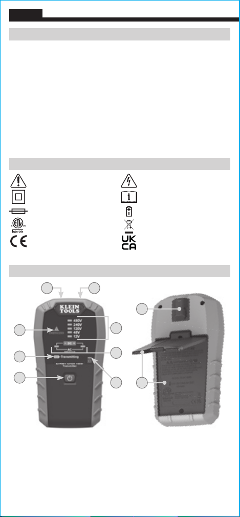
TRANSMITTER FEATURE DETAILS
FRONT BACK
8 9
10
5
4
1
NOTE: No user-serviceable parts inside.
Power On/Off Button
1.
External Voltage Indicators
2.
AC/DC / Polarity Indicators
3.
Transmitting Indicator
4.
Energized/ELV Indicator
5.
Low Battery Indicator
6.
4
2
3
6
7
Battery Cover with kickstand
7.
"COM" Jack
8.
"+ 600V" Jack
9.
Attachment Point for Optional
10.
Magnet Holder
RECEIVER SPECIFICATIONS
• Detecting Frequency: 33kHz
• Sensitivity: 8 levels
• Signal Strength: 0-99 on LCD, 0-10 bar display
• Signal Indicator: Audible (tone) and visual (LED)
• Tracing depth: 0' – 1.64' (0 – 0.5 m), depending on medium/application
• NCV: 80 to 1000V AC, 50/60Hz
• Flashlight: 6 Lumens
• Dimensions: 8.72" × 2.07" × 1.51" (221.5 × 52.8 × 38.5 mm)
• Weight (including batteries): 11 oz. (312g)
• Battery Type: 4 × 1.5V AA Alkaline
• Battery Life: Approximately 28 hours
• Auto-Power Off: After 10 minutes of inactivity
Specifications subject to change.
SYMBOLS ON RECEIVER
Warning Risk of electric shock
Double insulated Read Instructions
Conformité Européenne:
Conforms with European
Economic Area directives
WEEE – Electronics disposal Battery orientation
UKCA - United Kingdom
Conformity Assessment
Independently tested by Intertek
and meets applicable standards
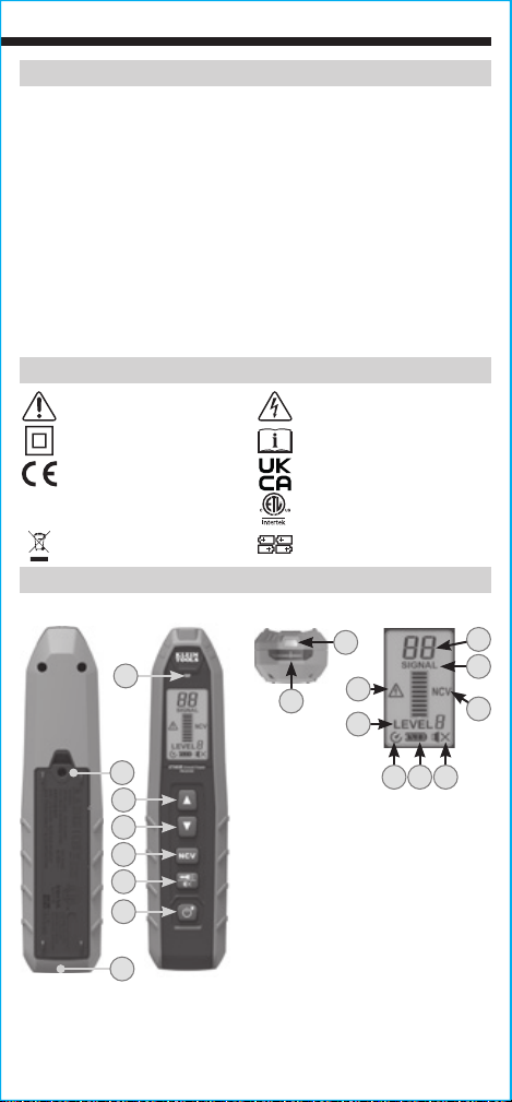
RECEIVER FEATURE DETAILS
FRONTBACK
TOP
9
8
7
LCD
11
12
15
13
14
6
4
5
3
2
1
10
Power On/Off / Backlight Button
1.
Flashlight/Mute Button
2.
NCV Button
3.
Increase Sensitivity Button
4.
Decrease Sensitivity Button
5.
1716 18
NOTE: No user-serviceable
parts inside.
Battery Cover
6.
Crosshair Grooves
7.
NCV Signal / Tracing Signal Indicator
8.
Flashlight
9.
Lanyard Hole
10.
Numerical Signal Strength (0-99)
11.
Bar graph (Signal Strength)
12.
Sensitivity Level (1-8)
13.
Non-Contact Voltage Indicator
14.
Hazardous Voltage Indicator
15.
Auto-Power Off (APO) Indicator
16.
Battery Status Indicator
17.
Mute Indicator
18.
5
ENGLISH
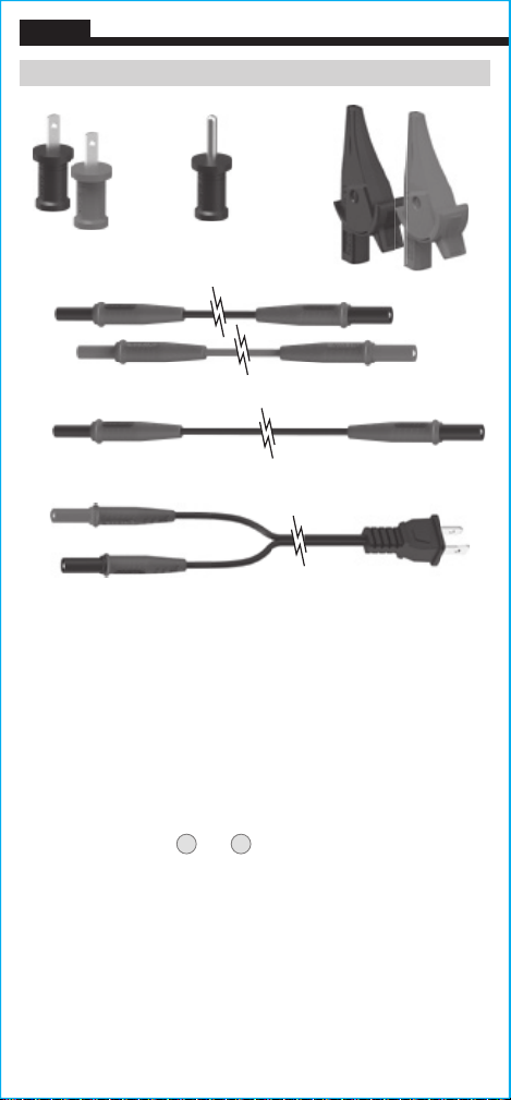
TEST LEAD KIT AND ACCESSORIES
A. B.
D.
E.
F.
Blade Prongs (Red ×1, Black ×1)
A.
Ground Prong
B.
Alligator Clips (Red ×1, Black ×1)
C.
3' (0.9 m) Lead Adapters (Red ×1, Black ×1)*
D.
20' (6 m) Lead Adapter*
E.
AC Plug Leads
F.
C.
*NOTE: Lead AdaptersD andE can all be connected end-to-end
for additional length when needed.
6
TRANSMITTER FUNCTION BUTTONS
ON/OFF
To power ON the Transmitter, long-press the ON/OFF button1.
The Transmitting Indicator4 will blink, indicating that it is transmitting, and
the Energized/ELV Indicator5 and the External Voltage Indicators2 will
illuminate in the presence of voltage greater than 25V AC/DC. By default, the
Transmitter will automatically power off after 4 hours of inactivity. To power
OFF the Transmitter, long-press the ON/OFF button1 for 2 seconds.
If the Energized/ELV Indicator 5 is blinking, voltage greater
than 480V AC/DC is detected. DISCONNECT TRANSMITTER FROM
CIRCUIT IMMEDIATELY.
RECEIVER FUNCTION BUTTONS
ON/OFF
To power ON the Receiver, long-press the ON/OFF Button 1. To power OFF
the Receiver, long-press the ON/OFF Button 1.
The Auto-Power Off icon will be visible on the display. By default, the tester will
automatically power off after 10 minutes of inactivity.
BACKLIGHT
Short-press the
SENSITIVITY LEVELS
Press the Increase Sensitivity
select one of the Receiver’s 8 sensitivity levels (level 8 is highest sensivity,
level 1 is lowest).
NOTE: Energized circuits typically use sensitivity levels 1-3, and
de-energized circuits may need higher sensitivity levels 4-8.
NCV
Power on the Receiver, and press the NCV Button 3 to put the Receiver
into NCV mode. Place the tip of the Receiver near the target area, or place the
wire on the tip of the Receiver to determine if the wire is energized. When an
energized wire is detected, the Bar Graph 12 will illuminate in relation to the
signal strength, the Green indicator LED will illuminate, and the speaker will
emit an audible signal.
MUTE
Long-press and hold the Flashlight/Mute Button 2 to mute/unmute audible
signals.
FLASHLIGHT
Short-press the Flashlight/Mute Button 2 to turn the flashlight on/off.
ON/OFF Button 1 to turn the LCD backlight on/off.
4
and Decrease Sensitivity 5 buttons to
NOTE: The Transmitter is not needed for NCV Mode.
7

ENGLISH
OPERATING INSTRUCTIONS
Before testing, verify the Receiver is functioning properly by placing
it near the powered Transmitter. With the Receiver set to Sensitivity
Level 8, a numerical reading of 99, all 10 signal strength bars lit up,
and a strong audible signal confirms the system is working. The
Receiver will produce a variable beep proportional to the sensitivity
value. The higher the signal strength, the faster it will beep.
NOTE: A continuous beep or solid-on LED indicates strongest
possible signal of 99 and the Receiver is saturated.
NOTE: If the Transmitter is powered up normally but the Receiver
detects a very low signal level, even when set to the highest
sensitivity level, the internal protection fuse in the Transmitter
should be checked, as it may be blown.
CONNECTING TEST LEADS
Connect test leads by inserting the black lead into the "COM" jack and
the red lead into the "+ 600V" jack. Do not test if leads are improperly
seated. Results could cause intermittent display readings. To ensure
proper connection, firmly press leads into the input jack completely.
NOTE: Test leads used must have a CAT III 600V safety rating.
CORRECT
INCORRECT
8

OPERATING INSTRUCTIONS
TRANSMITTER DIRECT AND REMOTE GROUND CONNECTION METHODS
DIRECT GROUND: In a direct ground connection, a plug or clips can
be connected to the hot and neutral wires on the same circuit.
NOTE: While locating a breaker, the wires will not be as traceable due
to the cancellation effects of the wires running parallel.
F
REMOTE GROUND: Preferred for optimum signal strength. To optimize
the transmitted signal and avoid cancellation effects which occur in a
direct ground connection, a remote ground connection should be used.
Attach the Ground ProngB to the 20' (6 m) Lead AdapterE and
connect to the ground of an outlet on a different circuit. Attach the red
Blade ProngA to the red test leadD and connect to the hot wire of
the circuit you are tracing.
E D
A
B
NOTE: This Remote Ground connection method will trip GFCI receptacles.
Several workarounds are available: Use the Direct Ground method,
connect directly to wires with alligator clips
C
, or de-energize circuit by
turning off breaker at the panel.
9

ENGLISH
OPERATING INSTRUCTIONS
RECEIVER ORIENTATION
The orientation of the Receiver in relation to the wire being traced is very
important. The vertical Crosshair Groove
7
on the tip of the Receiver
indicates the preferred direction of the wire for the strongest signal
detection. While tracing a wire, rotate the Receiver to always ensure the
highest signal value is displayed. The signal may not be detected if the
Receiver tip is not properly aligned to the wire. If the signal drops, the wire
may have changed direction (horizontal to vertical or vertical to horizontal).
Whenever possible, keep the Receiver at least 3' (0.9 m) away from the
Transmitter and test leads to reduce signal interference.
7
APPLICATIONS
WIRE
Circuit Breaker Finder (energized and de-energized)
1. Connect the Transmitter to the circuit to be identified using either the direct
ground or remote ground connection and power the Transmitter on. The
direct ground and remote ground connection methods can be used on both
energized and de-energized circuits, but an energized circuit produces a higher
signal strength.
2. Verify that the Energized Indicator on the Transmitter is illuminated if
connected to a circuit with voltage above 25V AC/DC and is not illuminated for
de-energized circuits.
3. Go to the electrical panel and power on the Receiver. If there is more than one
panel, touch the tip of the Receiver to each panel cover to identify the panel
4
with the highest signal level. Use the Increase Sensitivity
and Decrease
Sensitivity 5 buttons to adjust the Receiver sensitivity level to identify the
panel with the highest reading.
4. Once the panel has been identified, open the cover.
5. Orient the Receiver facing left or right and perpendicular to the breakers (See
below). Slowly move the Receiver up and down in front of each breaker. Use
4
the Increase Sensitivity
buttons to adjust the Receiver sensitivity levels as
5
and Decrease Sensitivity
needed to locate the breaker with the highest reading.
After any sensitivity level changes, rescan all the
breakers to find the breaker with
the highest reading.
NOTE: Energized circuits typically use
sensitivity levels 1-3, and de-energized circuits may need
higher sensitivity levels 4-8.
NOTE: If two or more breakers have the same signal value,
remove the panel cover and place the tip of the Receiver on
the individual wires to help in determining the correct breaker.
NOTE: Ensure the wire is held in the proper orientation in
relation to the tip of the Receiver.
10

OPERATING INSTRUCTIONS
TRACING WIRES
1. Connect the Transmitter to the circuit to be traced and power on
the Transmitter.
NOTE: The direct ground and remote ground connection methods
can be used on both energized and de-energized circuits, but an
energized circuit produces a higher signal strength.
2. Power on the Receiver, and use the Increase Sensitivity button 4
to set the Sensitivity Level to 8 (highest level).
3. Starting a few feet from the Transmitter, slowly move the Receiver
around to locate the direction of the strongest signal. The wires may
be located behind the wall, in the ceiling, or underneath the floor.
NOTE: If the signal strength displays “99”, the signal is saturated.
Use the Decrease Sensitivity button 5 to reduce the sensitivity level.
NOTE: If the signal strength is too weak, use the Remote Ground
connection method (if not done already) to strengthen the signal.
4. Continue to follow the location of the highest signal strength until
the destination is reached.
NOTE: If the circuit is de-energized, the Transmitter can be
connected to the neutral and ground wires, which will create a
stronger closed loop signal, as neutral and ground are bonded
together at the panel.
TRACING LOW VOLTAGE AND DATA CABLES
Follow the same steps outlined for Tracing wire above, with the wires
de-energized and utlizing a remote ground connection method.
NOTE: For shielded cables, connect the red test lead to the shield
of the cable being traced. Ground the far end of the cable shield if
possible.
FINDING OPENS/BREAKS
Follow the same steps outlined for Tracing wire above, except make
sure to ground any other wires running in parallel with the wire being
traced. Follow the signal strength until you observe it starting to drop
off. Use the sensitivity arrow keys to lower the sensitity level to pin
point the location of the open/break.
11

ENGLISH
OPERATING INSTRUCTIONS
TRACING WIRES INSIDE METAL CONDUIT
Due to metal conduit shielding the wire being traced, the Receiver
will be prevented from picking up the signal from the Transmitter. To
trace wire inside of metal conduit:
1. Connect the Transmitter to the circuit to be traced and power on
the Transmitter.
2. Power on the Receiver, and use the Increase Sensitivity button
4
to set the Sensitivity Level to 8 (highest level).
3. Hold the Receiver in front of junction boxes to check for the signal
being transmitted from the Transmitter.
4. If there is no signal detected, the junction box may need to be opened
so that the tip of the Receiver can be held in front of each wire.
5. Continue along each junction box until the destination is reached
or until the end of the circuit.
NOTE: If the conduit is non-metallic, the standard wire tracing
steps can be followed.
MAPPING A CIRCUIT
1. Turn off the breaker of the circuit being traced.
2. Remove the hot wire from the circuit breaker and connect the red
test lead of the Transmitter to the wire.
3. Connect the black test lead of the Transmitter to a remote ground
(see the Direct and Remote Ground connection methods sections)
and then power on the Transmitter.
4. Starting a few feet from the Transmitter, use the tip of the Receiver
to scan face plates of receptacles, wires, and other loads.
NOTE: If the signal strength displays “99”, the signal is saturated.
Use the Decrease Sensitivity button 5 to reduce the sensitivity level.
NOTE: If the signal strength is too weak, use the Remote Ground
connection method (if not done already) to strengthen the signal.
Any locations which indicate a signal are connected to the specific
breaker.
12
OPERATING INSTRUCTIONS
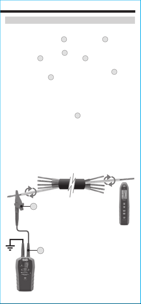
IDENTIFYING SINGLE CONDUCTOR (SORTING BUNDLED WIRES)
1. Attach the red Blade ProngA to the red test leadD and connect
to the known end of the wire to be traced.
2. Connect the black test leadD to a remote ground using the
Ground ProngB or black alligator clipC (see Remote Ground
connection method section), then power on the Transmitter.
3. Power on the Receiver, and use the Increase Sensitivity 4 and
Decrease Sensitivity 5 buttons to set the Sensitivity Level to 1-3.
4. Go to the other end of the cable, and one by one, pull each wire
away from the others, and touch the tip of the Receiver to the
wire. Ensure the wire is held in the proper orientation in relation
to the tip of the Receiver.
NOTE: If the signal strength displays “99”, the signal is saturated.
Use the Decrease Sensitivity button 5 to reduce the sensitivity level.
NOTE: If the signal strength is too weak, use the Remote Ground
connection method (if not done already) to strengthen the signal.
5. If multiple wires have the same sensitivity reading, pull back the
wires to separate them more if possible.
6. The highest signal value indicates the correct wire.
C
D
13
ENGLISH
OPERATING INSTRUCTIONS
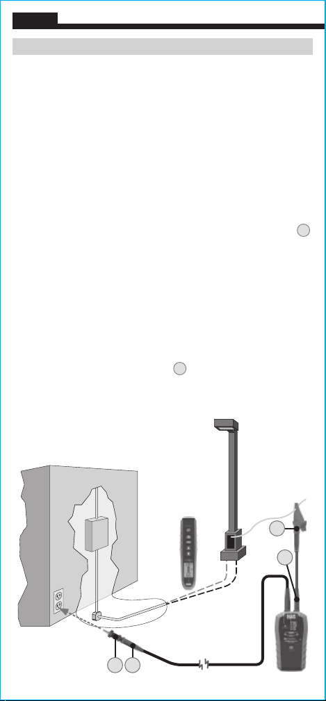
TRACING UNDERGROUND
1. Connect the Transmitter to the circuit to be traced and power on
the Transmitter.
NOTE: The Receiver may not detect and trace easily through metal
conduit/pipe or shielded cables. If the conduit is metal, or the wire
is shielded, connect to the shield or conduit instead.
NOTE: For the strongest signal, the remote ground connection
method should be used.
NOTE: Leaving the circuit energized provides a stronger signal and
assists in tracing.
2. Power on the Receiver, and use the Increase Sensitivity button
to set the Sensitivity Level to 8 (highest level).
3. Starting a few feet from the Transmitter, hold the Receiver
perpendicular to the ground and slowly move it around using a
sweeping motion to locate the highest signal value. Pay close
attention to the orientation of the Receiver in relation to the wire
being traced. The signal may not be detected if the Receiver tip is
not properly aligned to the wire. If the signal drops, the wire may
have changed direction.
4
NOTE: If the signal strength displays “99”, the signal is saturated.
Use the Decrease Sensitivity button 5 to reduce the sensitivity level.
NOTE: If the signal strength is too weak, use the Remote Ground
connection method (if not done already) to strengthen the signal.
C
D
B E
14

BATTERY REPLACEMENT
TRANSMITTER
When the Low Battery Indicator6 illuminates, the batteries must be
replaced:
1. Loosen 2 screws and remove Battery Cover
.
7
2. Remove and recycle spent batteries.
3. Install 6 new AA 1.5V batteries (4 inside battery door, 2 inside unit
housing), noting proper polarity.
4. Replace Battery Cover and tighten screws. Do not overtighten.
RECEIVER
When the Battery Status Indicator17 shows only 1 bar, the batteries
must be replaced.
1. Loosen screw and remove Battery Cover
.
7
2. Remove and recycle spent batteries.
3. Install 4 new AA 1.5V batteries, noting proper polarity.
4. Replace Battery Cover and tighten screws. Do not overtighten.
To avoid risk of electric shock:
•
Disconnect leads from any voltage source before removing
battery cover.
•
Do not operate while battery cover is removed.
FUSE REPLACEMENT
A fuse may blow if more than 600V energized is applied to the ET450
Transmitter. To access fuse:
1. Loosen 2 screws and remove Battery Cover
.
7
2. Replace blown fuse with 500mA/600V fast-blow, interrupting
rating 50kA.
3. Replace Battery Cover and tighten screws. Do not overtighten.
15
 Loading...