

Page 1

ENGLISH
INSTRUCTION MANUAL
Combustible Gas
Leak Detector
• DETECTS A RANGE
OF COMBUSTIBLE
GASSES
• AUDIBLE AND
VISUAL ALARMS
• DATA HOLD
ET120
99 Washi
M
Phone 781-665-1400
Toll Free 1-800-517-8431
Visit us at www.TestEquipmentDepot.com
ngton Street
elrose, MA 02176
Page 2

ENGLISH
GENERAL SPECIFICATIONS
Klein Tools ET120 is an easy-to-use tester that provides audible and
visual alarms in the presence of methane, propane and butane at
concentrations as low as 50 ppm.
•
Audible Alert:
concentration
• Visual Alert: 5 x red LED,
• Range*: 50 to 10,000 ppm
LOW sensitivity* (white light): 1,000 to 10,000 ppm
HIGH sensitivity* (yellow light): 50 to 1,000 ppm
• Initial calibration: 50 seconds to zero calibration
•
Response time (after calibration):
• Sensor: Electrochemical
•
Sensor Life expectancy:
• Probe: 18" (457 mm) gooseneck
• Batteries: 4x AAA alkaline
•
Operating Altitude:
• Relative Humidity: <80% non-condensing
•
Operating T
•
Storage T
• Dimensions: 8.11" x 2.72" x 1.75" (206 x 69 x 45 mm)
•
eight: 15 oz. (425 g) including batteries
W
• Tripod Mount: 1/4-20 UNC
• Drop Protection:
85 db ticking, modulation proportional to gas
illumination proportional to gas concentration
3 seconds
5 to 7 years
6562 ft. (2000 m)
emp: 32° to 122°F (0° to 50°C)
emp: -4° to 122°F (-20° to 50°C)
6.6 ft. (2m)
*Based on Methane. Other gasses or mixtures will have different values.
Specifications subject to change.
WARNINGS
To ensure safe operation and service of the tester, follow these
instructions. Failure to observe these warnings can result in severe
injury or death. High concentrations of combustible gasses can
cause explosions, res, asphyxia, and other hazards that could cause
serious personal injury or death. Know the characteristics of the gas
you are working with and use proper precautions to avoid hazardous
conditions.
• Read, understand, and follow all instructions to ensure safe operation.
• Always turn on the gas detector in an area known to be free of combustible
gasses.
• Initial calibration should be performed in an area known to be free of
combustible gasses. Calibration in an area containing combustible gas will
result in incorrect calibration and lower than actual readings. This could
result in combustible gasses not being detected.
• The combustion gas leak detector is NOT intended as a personal protection
device (PPE).
• Do NOT replace batteries in an explosive atmosphere.
• The combustion gas leak detector is NOT insulated. Avoid contact with
areas where energized conductive elements may be present. Shut off
power to the area before starting measurements.
• Do NOT probe moving machinery that could catch any part of the meter
and cause harm to the operator and the meter.
• Always wear approved eye protection.
2
Page 3
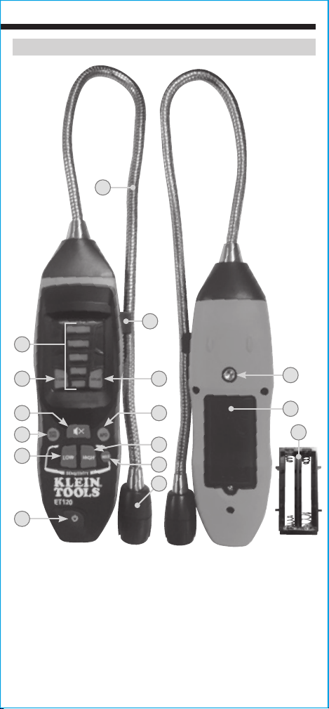
Front of
Tester
4
FEATURE DETAILS
1
2
Back of
Tester
5
8
7
10
6
9
11
12
3
13
Gooseneck
1.
Gooseneck Clip
2.
Sensor Head
3.
Indicator Lights
4.
LOW Alert Light
5.
HIGH Alert Light
6.
Auto-Zero Button
7.
Mute Button
8.
Auto Power-Off Button
9.
LOW Sensitivity Mode Button
10.
HIGH Sensitivity Mode Button
11.
HOLD Button
12.
Power Button
13.
1/4-20 UNC Tripod Mount
14.
Battery Door
15.
Battery Cartridge (inside battery compartment)
16.
NOTE: There are no user-serviceable parts inside tester.
14
15
16
3
Page 4
ENGLISH
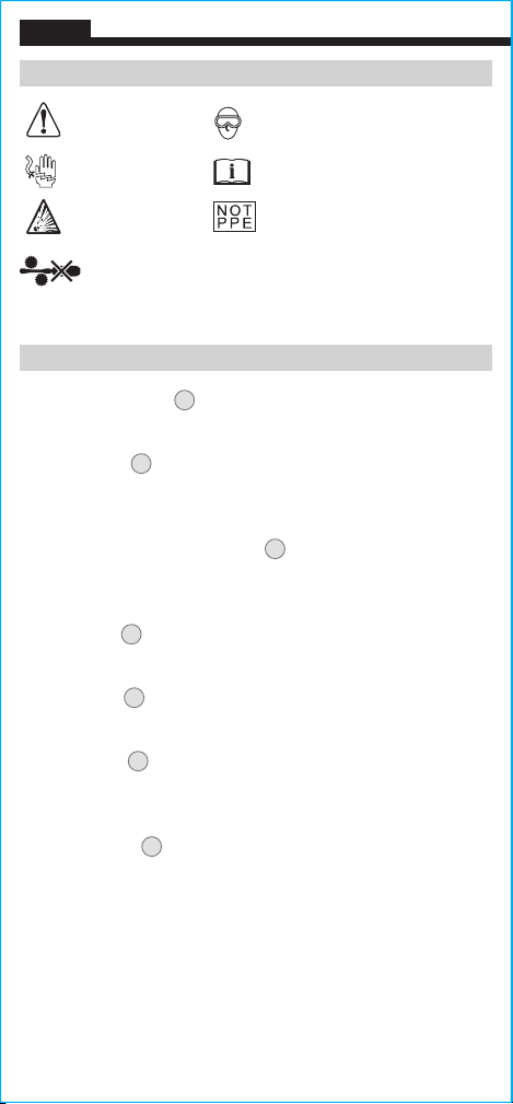
SYMBOLS ON METER
Warning
Risk of
Electric Shock
Explosive Materials
Wear approved eye protection
Read instructions
Not intended for use as Personal
Protective Equipment (PPE)
Do NOT probe
moving machinery
FUNCTION BUTTONS
AUTO-ZERO BUTTON 7
Press to set zero point in a known clean environment.
MUTE BUTTON
8
Press to mute the audible alarm. Visual indicators will continue to
function as normal
.
AUTO POWER-OFF (APO) BUTTON 9
Press to enable or disable the Auto Power-Off feature. When enabled,
the tester will automatically power off after 10 minutes of inactivity.
LOW BUTTON
10
Press to enter Low Sensitivity mode (1,000 to 10,000 ppm).
HIGH BUTTON 11
Press to enter High Sensitivity mode (50 to 1,000 ppm).
HOLD BUTTON 12
Press to lock the current measurement on the screen. Press again to
return to taking active measurements.
POWER BUTTON
13
Press to turn tester on and off.
4
Page 5

OPERATING INSTRUCTIONS
1. In an area where combustible gas is known to be not present,
press the power button
13
for 3 seconds. The tester will beep and
start a 50-second zero-calibration process while the first indicator
light blinks
one second, then the HIGH
4
. Once complete, all indicator lights 4 will blink for
6
indicator light will illuminate and
continue to flash, indicating it is ready to take a measurement.
2.
Start measuring in the High sensitivity mode (50 to 1,000 ppm).
o view higher values (1,000 to 10,000 ppm), press the LOW
T
10
button
3.
Point the sensor
to enter Low sensitivity mode.
3
towards the area to test. As all indicator
lights are illuminated in High sensitivity mode, switch to Low
sensitivity mode by pressing the LOW button
10
. NOTE: This may
cause most of the indicator lights to turn off. In Low sensitivity
mode, concentration levels are measured in larger intervals than
in High sensitivity mode, meaning greater concentration levels are
required to illuminate each indicator light.
4.
As you get closer to the sour
ce of a leak, the concentration levels
detected will increase, as indicated by increasing audible/visual
alarms. Move the sensor head in the direction of increasing
audible/visual alerts to the source of the leak.
WARNING: High concentrations of combustible gasses can
cause explosions, res, asphyxia, and other hazards that
could cause serious personal injury or death. Know the
characteristics of the gas you are working with and use proper
precautions to avoid hazardous conditions.
Page 6
ENGLISH
MAINTENANCE
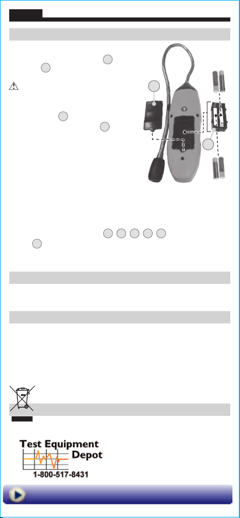
BATTERY REPLACEMENT
When both the LOW alert light 5 and HIGH
alert light
the batteries must be replaced.
WARNING:
in an explosive atmosphere.
are illuminated at the same time,
6
Do NOT replace batteries
15
1. Loosen screw and remove
battery door
2. Remove battery cartridge
from battery compartment.
Note orientation.
.
15
16
16
3. Remove and recycle
4 spent AAA batteries.
4. Install 4 new AAA batteries into
cartridge, noting proper polarity.
5. Place battery cartridge back into the
battery compartment, aligning the leads (fits only one way).
6. Replace battery door and tighten screw securely.
SENSOR SERVICING
When ALL lights on the tester
4, 5, 6, 7, 8
are illuminated, the
sensor 3 has failed and the unit must be serviced. Contact Klein Tools
at 1-877-775-5346 or [email protected] for further
There are no user-serviceable parts inside tester.
details.
CLEANING
Be sure tester is turned off and wipe with a clean, dry lint-free
cloth.
Do not use abrasive cleaners or solvents.
STORAGE
Remove the batteries when the tester is not in use for a prolonged
period of time. Do not expose to high temperatures or humidity.
After a period of storage in extreme conditions exceeding the limits
mentioned in the General Specifications section, allow the tester to
return to normal operating conditions before using.
DISPOSAL / RECYCLE
Do not place equipment and its accessories in the trash.
Items must be properly disposed of in accordance with local
regulations. Please see www.epa.gov or www.erecycle.org
for additional information.
99
Washington Street
Melrose, MA 02176
Phone 781-665-1400
Toll Free 1-800-517-8431
Visit us at www.TestEquipmentDepot.com
 Loading...