

Page 1
ENGLISH
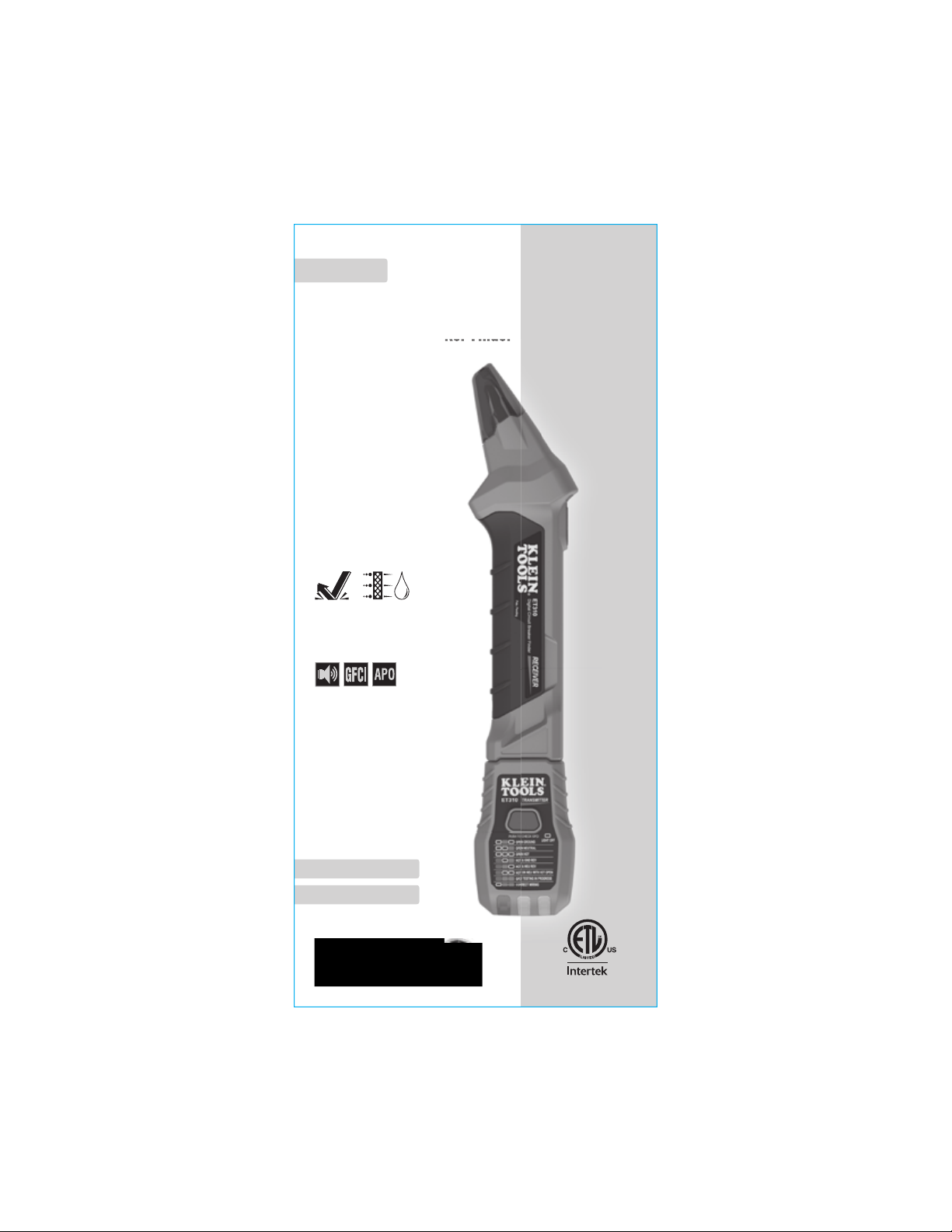
INSTRUCTION MANUAL
Digital Circuit Breaker Finder
• VISUAL & AUDIBLE
INDICATIONS
CLEARLY IDENTIFY
CORRECT BREAKER
• 90-120V AC
OPERATION
• DETERMINE WIRING
CONDITION AT
ELECTRICAL OUTLETS
• TEST GFCI DEVICES
2 m IP40
ET310
ESPAÑOL pág. 9
FRANÇAIS p. 17
5000573
Find Quality Products Online at: sales@GlobalTestSupply.com
www.GlobalTestSupply.com
Page 2

ENGLISH
GENERAL SPECIFICATIONS
The Klein Tools ET310 is a digital circuit breaker finder used to locate
the correct circuit breaker in a panel to which an electrical outlet or
fixture is connected. The transmitter is connected to the electrical
outlet or fixture in the circuit while the receiver is used to scan the
breakers in the circuit breaker panel.
• Operating Voltage: 90V to 120V AC, 50/60Hz
• Operating Altitude: 6562 ft. (2000m)
• Relative Humidity: <90% non-condensing
• Operating Temp: 32° to 122°F (0° to 50°C)
• Storage Temp: -4° to 122°F (-20° to 50°C)
• Dimensions (transmitter docked in receiver):
10.96" x 2.16" x 1.39" (278 x 55 x 35 mm)
• Weight (transmitter, receiver, and batteries): 7.2 oz. (204 g)
• Battery (receiver): 1 x 9V Alkaline (included)
• Auto-Power Off (receiver): Following 3 minutes of inactivity
• Standards:
Conforms to: UL STD 61010-1,
61010-2-030 1436.
Certified to: CSA STD C22.2 # 61010-1,
5000573
61010-2-030, 160.
• Drop Protection: 6.6 ft. (2m)
• Ingress Protection: IP40 dust resistant
• Pollution Degree: 2
Specifications subject to change.
SYMBOLS ON BACK OF TESTER
Risk of electric shock
Warning or Caution
Read Instructions WEEE – Battery disposal
This product has been independently
tested by Intertek and meets applicable
published standards.
FEATURE DETAILS
5 4
2
10
Transmitter
1.
Receiver
2.
Power On/Off/Reset Button
3.
Power On Indicator
4.
Sensing Tip
5.
Wiring Condition Indicators
6.
Wiring Condition Codes
7.
GFCI Test Button
8.
Circuit Status Indicator
9.
Battery Door
10.
Transmitter Docking Receptacle
11.
NOTE: There are no userserviceable parts inside.
FIG. 1
INDICATORS CONDITION INDICATED
Illuminated Red
Illuminated Orange
Not Illuminated
Open Ground
Open Neutral
Open Hot
Hot & Ground Reversed
Hot & Neutral Reversed
Hot On Neutral with Open Hot
GFCI Testing in Progress
Correct Wiring
9
3
11
1
8
7
6
2 3
Find Quality Products Online at: sales@GlobalTestSupply.com
www.GlobalTestSupply.com
Page 3

ENGLISH
WARNINGS
To ensure safe operation and service of the meter, follow these
instructions. Failure to observe these warnings can result in
severe injury or death.
• Failure to follow instructions could result in death or serious injury.
• Prior to use, always verify tester operation by testing on a known live
and correctly wired electrical outlet.
• DO NOT use if the tester appears damaged in any way.
• The tester is intended for indoor use only.
• The tester is designed for use with 120V AC electrical systems. DO
NOT connect to higher voltage electrical supplies.
• Other equipment or devices attached to the circuit being tested could
interfere with the tester, clear the circuit before testing.
• This tester only detects common wiring problems. Always consult a
qualified electrician to resolve wiring problems.
• If using accessories to connect to bare wires ensure that the circuit
is not energized before inspecting, applying, or removing the
transmitter.
• Exercise extreme caution around energized, bare wires, especially
when working in or around an open breaker panel.
POWER ON/OFF
Press the Power button
and hold the Power button
indicator
audible beep indicates that the unit is powered ON. The receiver
will automatically power off following 3 minutes of inactivity. The
transmitter
energized electrical outlet.
WIRING CONDITION
Prior to using this tester, always verify proper operation by
testing the transmitter on a known energized and correctly wired
electrical outlet.
Insert transmitter 1 into the electrical outlet being tested and compare
the illuminated wiring condition indicators
7
codes
If the tester indicates that the
outlet is not wired correctly, consult
a qualied electrician.
NOTE: Conditions NOT indicated
include but are not limited to quality of
ground, multiple hot wires, reversal of
neutral and ground conductors, dual
open ground and neutral, and other
combinations of defects.
NOTE: All appliances or equipment on the circuit being tested should
OPERATING INSTRUCTIONS
3
to power on the receiver 2, press
3
4
illuminated in the Sensing Tip 5 and pulsing
1
is powered by the circuit when inserted into an
printed on the transmitter (FIG. 1).
to power off the receiver. A green
6
with the wiring condition
be unplugged to help reduce the possibility of erroneous readings.
GFCI TEST
NOTE: Check the GFCI device’s user manual for information on how
the specific device operates prior to using this tester.
NOTE: All appliances or equipment on the circuit being tested should
be unplugged to help reduce the possibility of erroneous readings.
NOTE: Not designed for testing 30mA ground-fault devices.
Insert the transmitter into the electrical outlet and note the wiring
6 &
condition
7.
If the tester indicates that the outlet is not wired correctly, DO
NOT attempt to test the GFCI device. Consult a qualied electrician.
Press the GFCI button 8 on the transmitter 1 to test the GFCI device .
Following the test:
• If the GFCI device tripped, de-energizing the circuit, the wiring
condition indicators
device by pressing its reset button. After reset, the transmitter
should indicate Correctly Wired
to be functioning correctly.
• If the circuit remains Energized, the GFCI device didn’t trip, indicating
4 5
that it may be incorrectly wired, may not be installed correctly, or
may not be functioning correctly. Consult a qualified electrician.
6
will all be off (Open Hot). Reset the GFCI
6
& 7. The GFCI device appears
Find Quality Products Online at: sales@GlobalTestSupply.com
www.GlobalTestSupply.com
Page 4

ENGLISH
OPERATING INSTRUCTIONS
FINDING CIRCUIT BREAKERS
Insert the transmitter 1 into the electrical outlet and note the Wiring
Condition 6 & 7. If the transmitter indicates that the outlet is
energized and correctly wired, prepare to scan the breakers in the
breaker panel with the receiver 2.
If the tester indicates that the outlet is not wired correctly,
cease testing and consult a quali ed electrician.
Power ON the receiver. Before approaching the electrical panel, push
the Power On/Off/Reset button 3 once to reset the receiver. Position
the receiver so that the sensing tip 5 is oriented perpendicular to the
breakers in the panel. Slowly scan all breakers in the panel once, ignoring
any audible or visual indications as the receiver is learning the panel.
Scan all breakers a second time. When the breaker connected to
the circuit with the transmitter is approached, the frequency of the
audible beeps will increase. When located, the audible beep will sound
continuously, the circuit status indicator will illuminate red 9, and the
green indicator in the sensing tip 4 will turn off, indicating that the
correct breaker has been found.
NOTE: Resetting the receiver erases prior scanning data stored from
a previously ‘learned’ panel. Always reset the receiver away from
the electrical panel to ensure that electrical signals are not being
sensed during the reset operation.
OPERATING INSTRUCTIONS
CONNECTING TO OTHER FIXTURES USING OPTIONAL ACCESSORIES
(CAT. NO. 69411)
LIGHT SOCKET FIXTURES
Screw the light fixture adapter into an empty light socket. Connect the
transmitter 1 to the 3-to-2 prong adapter, and connect this to the light
fixture adapter. The indicators on the transmitter will communicate an
open ground wiring condition if the light socket is energized. Follow
the instructions in the FINDING CIRCUIT BREAKERS section to find the
correct circuit breaker.
Light Fixture
Adapter
BARE WIRES
The transmitter may be connected to bare wires using the outlet-toalligator clips wire adapter. Carefully attach the alligator clips the correct
wires. Insert transmitter into the outlet on the wire adapter. The indicators
on the transmitter will communicate an open ground wiring condition if
the wires are energized. Follow the instructions in the FINDING CIRCUIT
BREAKERS section to find the correct circuit breaker.
Exercise extreme caution when working around energized
3-to-2 prong
adapter Transmitter
1
bare wires.
6 7
Find Quality Products Online at: sales@GlobalTestSupply.com
www.GlobalTestSupply.com
Page 5

ENGLISH
MAINTENANCE
BATTERY REPLACEMENT
When the Power-On indicator 4 blinks, the battery must be replaced.
1. Open the battery compartment door 10 by unscrewing the
locking screw.
2. Remove exhausted 9V battery and dispose of appropriately.
3. Replace the 9V battery, close the battery door, and re-fasten the
locking screw.
CLEANING
Be sure unit is turned off and wipe with a clean, dry lint-free cloth.
Do not use abrasive cleaners or solvents. Take care to keep the
sensor lens clean at all times. If required, loose debris may be
removed from lens using clean compressed air. Lens may also be
cleaned using a soft cloth or cotton swab with water or rubbing
alcohol only. Lens must be allowed to completely dry prior to use.
STORAGE
The transmitter 1 may be docked in the transmitter receptacle
in the receiver 2 for convenient storage. Remove the batteries when
the tester will not be used for a prolonged period of time. Do not
expose to high temperatures or humidity. After a period of storage
in extreme conditions exceeding the limits mentioned in the General
Specifications section, allow the tester to return to normal operating
conditions before using.
WARRANTY
11
DISPOSAL / RECYCLE
Do not place equipment and its accessories in the trash.
Items must be properly disposed of in accordance with local
regulations. Please see www.epa.gov or www.erecycle.org
for additional information.
8
Find Quality Products Online at: sales@GlobalTestSupply.com
www.GlobalTestSupply.com
 Loading...