

Page 1
ENGLISH
600V
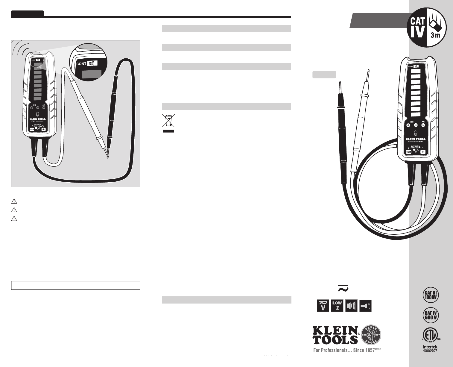
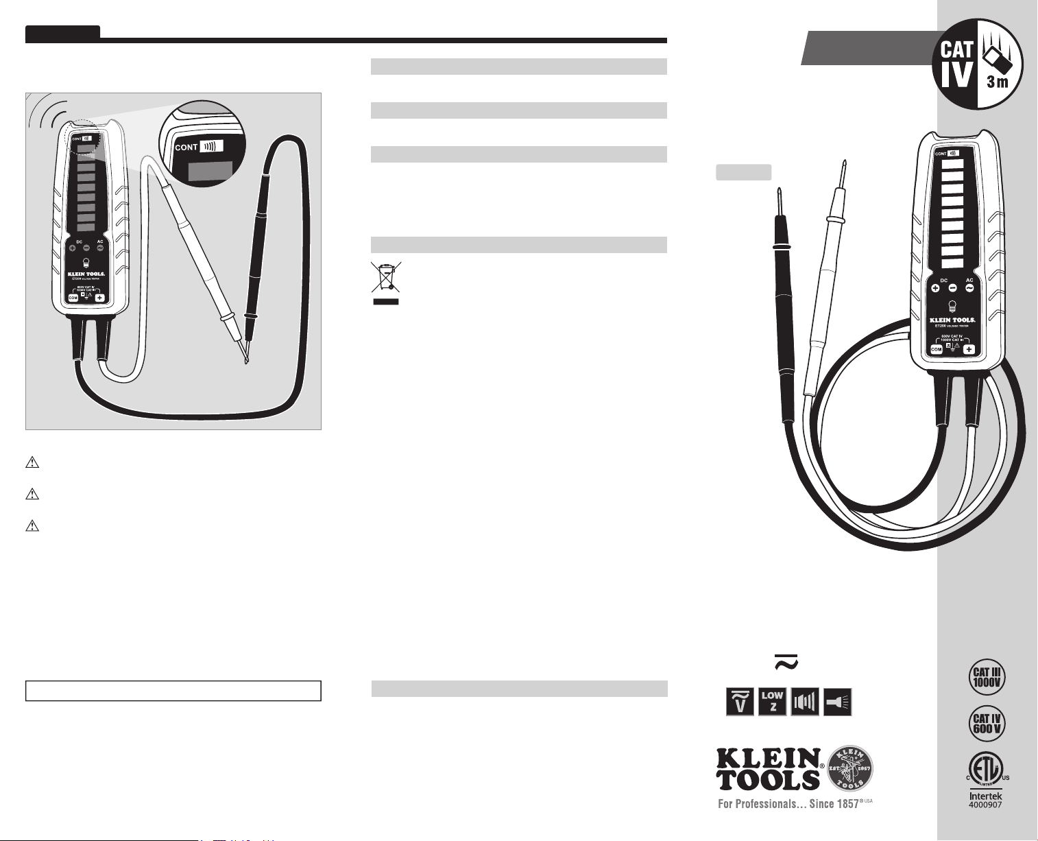
Continuity Testing
Continuity is indicated at less than 270kΩ of resistance.
600
480
277
240
208
120
48
24
12
600
WARRANTY
www.kleintools.com/warranty
CLEANING
Clean the instrument by using a damp cloth. Do not use abrasive cleaners or solvents.
STORAGE
Remove the batteries when instrument is not in use for a prolonged period of
time. Do not expose to high temperatures or humidity. After a period of storage
in extreme conditions exceeding the limits mentioned in the Specifications
section, allow the instrument to return to normal operating conditions before
using it.
DISPOSAL / RECYCLE
Caution: This symbol indicates that equipment and its accessories
shall be subject to a separate collection and correct disposal.
ET200
Instruction Manual
ENGLISH
600
480
277
240
208
120
48
24
12
GFCI Testing
Check the GFCI Receptacle user manual for more information.
Always contact a qualified electrician to resolve wiring problems.
Operate the Push Button on the GFCI Receptacle. If the GFCI circuit
does not trip, the receptacle is not operating properly.
To test the functionality of a Ground Fault Circuit Interrupter receptacle,
apply leads to the hot and ground terminals for 7 seconds.
• If the GFCI receptacle is wired properly, power to the circuit
will go out and the ET200 will stop indicating voltage.
• If the GFCI receptacle is wired improperly, power to the circuit
will remain and the ET200 will continue to indicate voltage.
To resolve an issue, contact a qualified electrician.
Battery Replacement
Batteries are not required for visual voltage indication.
1. Remove test leads from voltage source.
2. Unscrew battery cover and replace 3xAAA batteries.
CUSTOMER SERVICE
KLEIN TOOLS, INC.
450 Bond Street
Lincolnshire, IL 60069
1-800-553-4676
customerservice@kleintools.com
www.kleintools.com
139645 Rev. 12/13 B
139575T Rev. 12/13 B
• MODERN
SOLID-STATE
DESIGN
• INDICATES VOLTAGE
WITHOUT BATTERY
• LOW IMPEDENCE
• CONTINUITY FUNCTION WITH
LIGHT, VIBRATION AND SOUND
INDICATIORS
Page 2
ENGLISH
ET200
Instruction Manual
GENERAL SPECIFICATIONS
The Klein Tools ET200 is a solid-state electrical tester. It measures AC/DC
voltage, tests continuity, and features a bright LED worklight.
• Voltage Level Indicators: 12, 24, 48, 120, 208, 240, 277, 480, 600
• Voltage Type Indicators: AC, DC Positive, DC Negative
• AC Frequency: 45Hz to 66Hz
• Maximum Voltage To Earth Ground: 600V RMS
• Maximum Measurable Voltage: 600V RMS (displayed by LEDs)
• Input Impedance: 15kΩ on connection, up to 150kΩ steady-state.
• Continuity: < 270kΩ
• Usage Duty Cycle (Above 277V): 1 minute on, 5 minutes off
• Accuracy: 70% to 100% of indicated voltage
• Battery Type: 3 x AAA
• Operating Altitude: 2000 m
• Relative Humidity: 32°F to 86°F (0°C to 30°C) 90%
86°F to 104°F (30°C to 40°C ) 75%
104°F to 131°F (40°C to 55°C) 45%
• Operating Temperature: 32°F to 131°F (0°C to 55°C)
• Storage Temperature: 32°F to 131°F (0°C to 55°C)
• Dimensions: 7.4 x 2.4 x 1.25 in. (187 x 60 x 32 mm)
• Weight: 8.1oz. (230 g)
• Safety: CSA C22.2-1010.1, IEC 61010-1, Pollution Degree II
• Safety Rating: CAT IV 600V, CAT III 1000V
• Drop Rating: 10 ft. (3 m)
WARNINGS
To ensure safe operation and service of the tester, follow these instructions.
Failure to observe these warnings can result in severe injury or death.
• Before each use, verify meter operation by measuring
a known voltage or current.
• Never use the meter on a circuit with voltages that exceed the
category based rating of this meter.
• Do not use the meter during electrical storms, or in wet weather.
• Do not use the meter or test leads if they appear to be damaged.
• Ensure meter leads are fully seated, and keep fingers away from
the metal probe contacts when making measurements.
• Do not open the meter to replace batteries while the probes
are connected to a voltage source.
• Use caution when working with voltages above 60V DC,
or 25V AC RMS. Such voltages pose a shock hazard.
• Shut off and lock out power before testing continuity.
• Always adhere to local and national safety codes. Use individual
protective equipment to prevent shock and arc blast injury where
hazardous live conductors are exposed.
SYMBOLS
Positive DC Voltage Warning or Caution
+
Negative DC Voltage Dangerous levels
–
AC Voltage Double Insulated Class II
~
Earth Ground ETL Certi cation
This product has been tested to the requirements of
CAN/CSA-C22.2 No. 61010-1, second edition, including
Amendment 1, or a later version of the same standard
incorporating the same level of testing requirements
CAT III CAT IV
Designed for transient protection
on indoor measurements at
installations connected directly
to the primary source. Examples
include distribution panels and
lighting systems in large buildings.
Designed for transient protection
on outdoor measurements taken
at the primary supply voltage
source. Examples include outdoor
overhead or underground utility
service and electricity meter.
FEATURE DETAILS
Indicators
Lights
• LEDs light up numerical voltage level indicators,
as well as AC and DC
• Continuity LED will light up on detection.
• Voltage detection will function without batteries installed.
Vibration
• Instrument will vibrate in the presence of voltage
measurements greater than 48V.
• Vibration will function only with batteries installed.
Sound
• Instrument will emit a tone in the presence of voltage
measurements greater than 48V.
• Instrument will emit a tone on detection of continuity.
• Sound will function only with batteries installed.
Accuracy
Accuracy of indicator lights is 70% to 100% of the voltage displayed
to account for normal variations in supply voltage.
Work Light
Press the light bulb button above the Klein Tools logo to toggle the
worklight on and off.
Ghost Voltages
The approximate input resistance of 15k
false readings due to ghost voltages on de-energized lines.
Lead Spacing
Molded lead holders on the back of the ET200 are spaced correctly
to test tamper-resistant outlets.
+ or DC – indicators.
Ω will reduce the possibility of
OPERATING INSTRUCTIONS
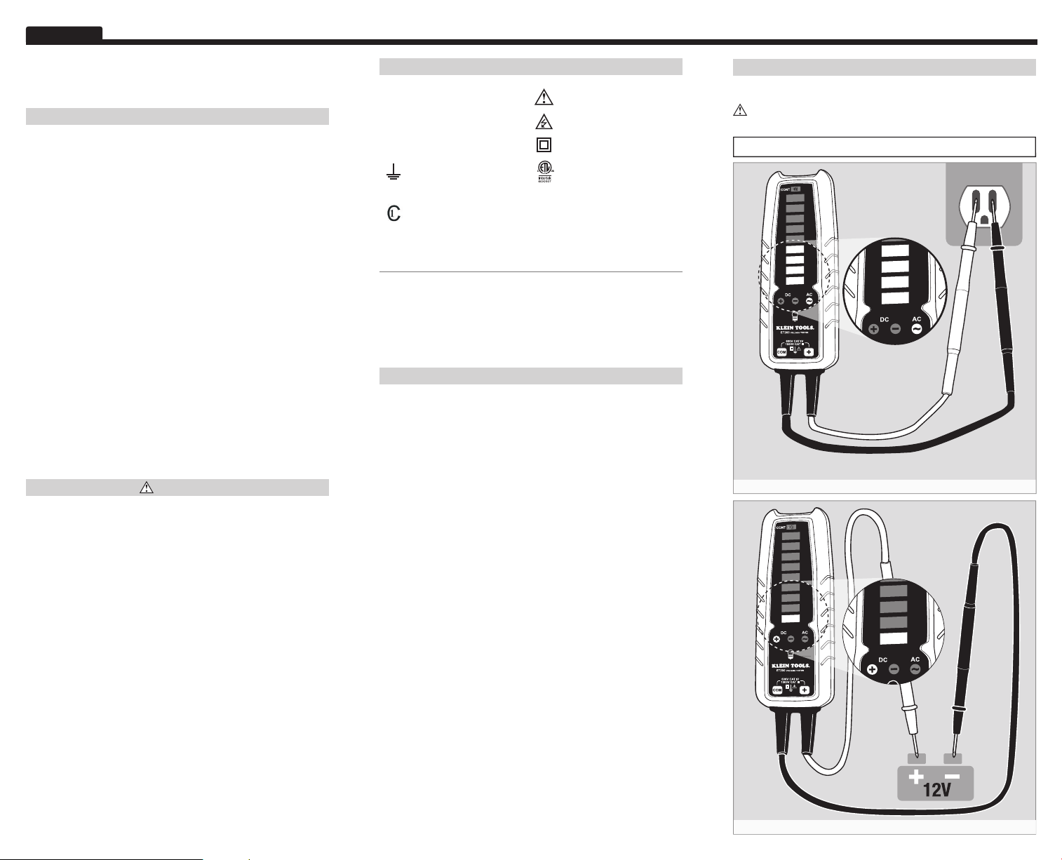
Measuring Voltages
Time spent operational at voltages above 277V must be less than
60 seconds, with a cool-off time of at least 5 minutes.
Tester will turn on automatically when voltage is applied.
600
480
277
240
208
120
48
24
12
AC Voltage Measurement
600
480
277
240
208
120
48
24
12
DC Voltage Measurement
120
48
24
12
120
48
24
12
Page 3
ESPAÑOL
600 V
Pruebas de continuidad
La continuidad se indica a menos de 270 kΩ de resistencia.
600
480
277
240
208
120
48
24
12
600
GARANTÍA
www.kleintools.com/warranty
LIMPIEZA
Limpie el instrumento con un paño húmedo. No utilice solventes ni limpiadores abrasivos.
ALMACENAMIENTO
Retire las baterías si no va a utilizar el instrumento durante un tiempo
prolongado. No lo exponga a la humedad ni a altas temperaturas. Luego de
un período de almacenamiento en condiciones extremas que sobrepasen los
límites mencionados en la sección Especificaciones, deje que el instrumento
vuelvaalas condiciones de funcionamiento normales antes de utilizarlo.
ELIMINACIÓN/RECICLAJE
Precaución: Este símbolo indica que el equipo y sus accesorios están
sujetos a una recolección por separado y su posterior eliminación correcta.
ET200
Manual de
instrucciones
ESPAÑOL
600
480
277
240
208
120
48
24
12
Pruebas de GFCI
Consulte el manual del usuario del receptáculo GFCI para obtener
másinformación.
Siempre contáctese con un electricista calificado para solucionar
problemas de cableado.
Accione el pulsador del receptáculo GFCI. Si el circuito de GFCI no se
acciona, el receptáculo no está funcionando correctamente.
Para probar la funcionalidad del receptáculo de un interruptor diferencial,
aplique cables de prueba a los terminales vivos y a tierra durante 7segundos.
• Si el receptáculo GFCI está correctamente conectado, saldrá
laenergía al circuito y el ET200 dejará de indicar el voltaje.
• Si el receptáculo GFCI está conectado incorrectamente, la energía
permanecerá en el circuito y el ET200 continuará indicando
el voltaje. Para resolver un problema, comuníquese con un
electricista calificado.
Reemplazo de la batería
No se requieren baterías para indicación visual de voltaje.
1. Retire los cables de prueba de la fuente de voltaje.
2. Desenrosque la tapa de las baterías y reemplace las 3 baterías AAA.
• DISEÑO
MODERNO EN
ESTADO SÓLIDO
• INDICA EL VOLTAJE
SIN BATERÍA
• BAJA IMPEDANCIA
• FUNCIÓN DE CONTINUIDAD
CON INDICADORES DE LUCES,
VIBRACIÓNYSONIDO
SERVICIO AL CLIENTE
KLEIN TOOLS, INC.
450 Bond Street
Lincolnshire, IL 60069
1-800-553-4676
customerservice@kleintools.com
www.kleintools.com
139576T Rev. 12/13 B
Page 4

ESPAÑOL
ET200
Manual de instrucciones
ESPECIFICACIONES GENERALES
ET200 de Klein Tools es un probador eléctrico en estado sólido. Se utiliza
para medir el voltaje de CA/CD, probar la continuidad y proporcionar luz
detrabajo de LED brillante.
• Indicadores de nivel de voltaje: 12, 24, 48, 120, 208, 240, 277, 480, 600
• Indicadores de tipo de voltaje: CA, CD positiva, CD negativa
• Frecuencia de CA: 45 Hz a 66 Hz
• Voltaje máximo a tierra: 600 V RMS
• Voltaje máximo mensurable: 600 V RMS (visualizado mediante LED)
• Impedancia de entrada: 15 kΩ en conexión, hasta 150 kΩ
en estado estacionario
• Continuidad: < 270 kΩ
• Ciclo de servicio de uso (por encima de 277 V): 1 minuto encendido,
5 minutos apagado
• Precisión: 70 % a 100 % del voltaje indicado
• Tipo de batería: 3 x AAA
• Altitud de funcionamiento: 2000 m
• Humedad relativa: 32 °F a 86 °F (0 °C a 30 °C) 90 %
86 °F a 104 °F (30 °C a 40 °C ) 75 %
104 °F a 131 °F (40 °C a 55 °C) 45 %
• Temperatura operativa: 32 °F a 131 °F (0 °C a 55 °C)
• Temperatura de almacenamiento: 32 °F a 131 °F (0 °C a 55 °C)
• Dimensiones: 7.4 x 2.4 x 1.25" (187 x 60 x 32 mm)
• Peso: 8.1 oz (230 g)
• Seguridad: CSA C22.2-1010.1, IEC 61010-1, Grado de contaminación II
• Clasifi cación de seguridad: CAT IV 600 V, CAT III 1000 V
• Resistencia a las caídas: 10 pies (3 m)
ADVERTENCIAS
Para garantizar un funcionamiento y servicio seguros del probador, siga
estas instrucciones. El incumplimiento de estas advertencias puede dar
lugar a lesiones o provocar la muerte.
• Antes de cada uso, verifique el funcionamiento del multímetro
midiendo un voltaje o corriente conocidos.
• Nunca debe utilizar este multímetro en un circuito con voltajes que
excedan la clasificación basada en categorías del multímetro.
• No utilice el multímetro durante tormentas eléctricas o en clima húmedo.
• No utilice el multímetro o los cables de prueba si en apariencia
estándañados.
• Asegúrese de que los cables del multímetro estén correctamente
colocados y mantenga los dedos lejos de los contactos de la sonda
de metal al realizar las mediciones.
• No abra el multímetro para reemplazar las baterías mientras las
sondas están conectadas a una fuente de voltaje.
• Proceda con precaución cuando trabaje con voltajes superiores a
60VCD o 25V CA RMS. Esos voltajes implican un riesgo de descarga.
• Apague y bloquee la energía antes de probar la continuidad.
• Cumpla siempre con los códigos de seguridad locales y nacionales.
Utilice equipo de protección individual para prevenir lesiones por
descarga y arco eléctrico en aquellos lugares donde se exponen
conductores activos peligrosos.
SÍMBOLOS
Voltaje de CD positiva Advertencia o precaución
+
Voltaje de CD negativa Niveles peligrosos
–
Voltaje de CA Doble aislamiento Clase II
~
Conexión a tierra Certi cación ETL
Este producto fue probado según los requisitos de CAN/
CSA-C22.2 N.° 61010-1, segunda edición, incluida la
Enmienda 1, o una versión posterior de la misma norma
queincorpore el mismo nivel de requisitos de prueba
CAT III CAT IV
Diseñado para protección
transitoria en mediciones
realizadas en interiores en
instalaciones conectadas
directamente a la fuente principal.
Los ejemplos incluyen paneles
de distribución y sistemas de
iluminación en grandes edificios.
Diseñado para protección
transitoria en mediciones
en exteriores tomadas en la
fuente de voltaje del suministro
principal. Los ejemplos incluyen
servicios desuministro aéreos
o subterráneos en exteriores
ymedidores de electricidad.
DETALLES DE LAS CARACTERÍSTICAS
Indicadores
Luces
• Los LED encienden indicadores de nivel de voltaje numéricos,
como así también indicadores de CA y CD +, o de CD –.
• El LED de continuidad se enciende al momento de la detección.
• La detección de voltaje funcionará sin baterías instaladas.
Vibración
• El instrumento vibrará en presencia de mediciones de voltaje
superiores a 48 V.
• La vibración funcionará únicamente con las baterías instaladas.
Sonido
• El instrumento emitirá un tono en presencia de mediciones
devoltaje superiores a 48 V.
• El instrumento emitirá un tono al momento de la detección
decontinuidad.
• El sonido funciona únicamente con las baterías instaladas.
Precisión
La precisión de las luces indicadoras es del 70% al 100% del voltaje
quese visualiza para las variaciones normales en el voltaje de suministro.
Luz de trabajo
Presione el botón de la bombilla de luz que se encuentra sobre el logotipo
de Klein Tools para encender y apagar la luz de trabajo.
Voltajes fantasma
La resistencia de entrada aproximada de 15 k
haya lecturas falsas a causa de voltajes fantasma en líneas desenergizadas.
Separación entre cables de prueba
Los portacables moldeados que se encuentran en la parte posterior del ET200
están correctamente separados para probar tomacorrientes inviolables.
Ω reducirá la posibilidad de que
INSTRUCCIONES DE OPERACIÓN
Voltajes de medición
El tiempo de funcionamiento a voltajes superiores a los 277 V debe ser
inferior a los 60 segundos, con un tiempo de enfriamiento de al menos
5 minutos.
El probador se encenderá automáticamente cuando se aplique voltaje.
600
480
277
240
208
120
48
24
12
Medición de voltaje de CA
600
480
277
240
208
120
48
24
12
Medición de voltaje de CD
120
48
24
12
120
48
24
12
Page 5

PORTUGUÊS
600V
Teste de continuidade
A continuidade é indicada quando menor que 270kΩ de resistência.
600
480
277
240
208
120
48
24
12
600
GARANTIA
www.kleintools.com/warranty
LIMPEZA
Limpe o instrumento usando um pano úmido. Não use produtos de limpeza
abrasivos ou solventes.
ARMAZENAMENTO
Remova as baterias quando o instrumento não estiver em uso por um longo
período de tempo. Não exponha o instrumento a altas temperaturas ou umidade.
Após um período de armazenamento em condições extremas que excedem os
limites mencionados na seção Especificações, deixe que o instrumento retorne
às condições normais de operação antes de usá-lo.
DESCARTE/RECICLAGEM
Cuidado: Este símbolo indica que o equipamento e seus acessórios
podem estar sujeitos a coleta e descarte separados.
Manual de
instruções
PORTUGUÊS
ET200
600
480
277
240
208
120
48
24
12
Teste de GFCI
Verifique o manual de usuário da tomada GFCI para obter mais informações.
Sempre entre em contato com um eletricista qualificado para resolver
problemas de fiação.
Opere o botão de pressão na tomada GFCI. Se o circuito GFCI não acionar,
a tomada não está operando adequadamente.
Para testar a funcionalidade de uma tomada de Interruptor com circuito
de falha de aterramento, aplique pontas de prova aos terminais quentes
eaterrados por 7 segundos.
• Se a tomada GFCI estiver conectada adequadamente, a alimentação
ao circuito irá parar e o ET200 irá parar de indicar tensão.
• Se a tomada GFCI estiver conectada de maneira incorreta,
aalimentação ao circuito irá continuar e o ET200 irá continuar
aindicar tensão. Para resolver um problema, entre em contato
com um eletricista qualificado.
Substituição da bateria
Baterias não são necessárias para indicação visual de tensão.
1. Remova pontas de prova da fonte de tensão.
2. Desaparafuse a tampa da bateria e substitua as baterias 3xAAA.
• DESIGN
SÓLIDO E
MODERNO
• INDICA TENSÃO
SEM BATERIA
• IMPEDÂNCIA BAIXA
• FUNÇÃO DE CONTINUIDADE
COM INDICADORES DE LUZ,
VIBRAÇÃO E SOM
ATENDIMENTO AO CLIENTE
KLEIN TOOLS, INC.
450 Bond Street
Lincolnshire, IL 60069
1-800-553-4676
customerservice@kleintools.com
www.kleintools.com
139834 Rev. 12/13 A
Page 6

PORTUGUÊS
ET200
Manual de instruções
ESPECIFICAÇÕES GERAIS
O Klein Tools ET200 é um testador elétrico de estado sólido. Ele mede tensão
AC/DC, testa continuidade e apresenta uma luz de trabalho de LED brilhante.
• Indicadores de nível de tensão: 12, 24, 48, 120, 208, 240, 277, 480, 600
• Indicadores de tipo de tensão: AC, DC positiva, DC negativa
• Frequência AC: 45 Hz a 66 Hz
• Tensão máxima ao ponto de aterramento: 600 V RMS
• Tensão máxima mensurável: 600 V RMS (exibido por LEDs)
• Impedância de entrada: 15 kΩ na conexão, até 150 kΩ
em estado estacionário.
• Continuidade: < 270 kΩ
• Ciclo de trabalho de uso (acima de 277 V): 1 minuto ligado,
5 minutos desligado
• Exatidão: 70% a 100% da tensão indicada
• Tipo de bateria: 3 x AAA
• Altitude de operação: 2000 m
• Umidade relativa: 32 °F a 86 °F (0 °C a 30 °C) 90%
86 °F a 104 °F (30 °C a 40 °C ) 75%
104 °F a 131 °F (40 °C a 55 °C) 45%
• Temperatura de operação: 32°F a 131°F (0°C a 55°C)
• Temperatura de armazenamento: 32°F a 131°F (0°C a 55°C)
• Dimensões: 7.4 x 2.4 x 1.25 in. (187 x 60 x 32 mm)
• Peso: 8.1 oz. (230 g)
• Segurança: CSA C22.2-1010.1, IEC 61010-1, Grau de poluição II
• Classifi cação de segurança: CAT IV 600V, CAT III 1000V
• Classifi cação de queda: 10 ft. (3 m)
ADVERTÊNCIAS
Para assegurar uma operação e serviço do testador seguros, siga estas
instruções. A não observância destas advertências pode resultar em
acidentes pessoais graves ou morte.
• Antes de cada utilização, verifique a operação do medidor medindo
uma tensão ou corrente conhecida.
• Nunca utilize o medidor em um circuito com tensões que excedem
aclassificação baseada em categorias deste medidor.
• Não utilize o medidor durante tempestades elétricas ou em
tempochuvoso.
• Não utilize o medidor ou as pontas de prova se aparentarem
estardanificados.
• Certifique-se de que os cabos do medidor estejam totalmente assentados
e mantenha os dedos afastados dos contatos de metal da sonda ao
realizar medições.
• Não abra o medidor para substituir baterias enquanto as sondas
estiverem conectadas à fonte de tensão.
• Tenha cuidado ao trabalhar com tensões acima de 60 V DC ou
25VAC RMS. Essas tensões podem causar choque elétrico.
• Desligue e bloqueie a alimentação elétrica antes de testar a continuidade.
• Esteja sempre em conformidade com as regulamentações de segurança
locais e nacionais. Use equipamento de proteção individual para evitar
choque elétrico e acidente pessoal por descarga de arco onde condutores
vivos perigosos estão expostos.
SÍMBOLOS
Tensão DC positiva Advertência ou cuidado
+
Tensão DC negativa Níveis de perigo
–
~
Tensão AC
Classe II de isolamento
duplo
Ponto de aterramento Certi cação ETL
Este produto foi testado de acordo com os requisitos do
padrãoCAN/CSA-C22.2 Nº 61010-1, segunda edição,
incluindoa Emenda 1, ou uma versão posterior do
mesmopadrão com o mesmo nível de requisitos de teste
CAT III CAT IV
Projetado para a proteção
de transientes em medições
internas em instalações
diretamente conectadas à fonte
primária. Exemplos incluem
quadros de distribuição
esistemas de iluminação
Projetado para a proteção de
transientes em medições externas
na fonte de tensão de alimentação
primária. Exemplos incluem
serviços de utilidade pública
externos aéreos ou subterrâneos
emedidores de eletricidade.
emgrandesconstruções.
DETALHES DE RECURSOS
Indicadores
Luzes
• LEDs iluminam os indicadores numéricos de nível de tensão,
assim como indicadores de AC e DC
• O LED de continuidade irá acender na detecção.
• A detecção de tensão irá funcionar sem baterias instaladas.
Vibração
• O instrumento irá vibrar na presença de medições de tensão
maiores do que 48 V.
• A vibração só funcionará com baterias instaladas.
Som
• O instrumento irá emitir um tom na presença de medições de
tensão maiores do que 48 V.
• O instrumento irá emitir um tom na detecção de continuidade.
• O som só funcionará com baterias instaladas.
Exatidão
A exatidão das luzes indicadoras é de 70% a 100% da tensão exibida
paraconsiderar as variações normais na tensão de alimentação.
Luz de trabalho
Pressione o botão de lâmpada acima do logotipo da Klein Tools para ligar
edesligar a luz de trabalho.
Tensões fantasma
A resistência de entrada aproximada de 15 k
deleituras falsas devido a tensões fantasma nas linhas desenergizadas.
Espaçamento de pontas
Os suportes de pontas moldados na parte de trás do ET200 têm
oespaçamento correto para testar tomadas invioláveis.
+, ou DC –.
Ω irá reduzir a possibilidade
INSTRUÇÕES DE OPERAÇÃO
Medição de tensões
O tempo de operação em tensões acima de 277 V deve ser menor do que
60 segundos, com um tempo de resfriamento de pelo menos 5minutos.
O testador ligará automaticamente quando a tensão for aplicada.
600
480
277
240
208
120
48
24
12
Medição de tensão AC
600
480
277
240
208
120
48
24
12
Medição de tensão DC
120
48
24
12
120
48
24
12
Page 7

FRANÇAIS
600 V
Test de continuité
La continuité est indiquée à une résistance inférieure à 270kΩ.
600
480
277
240
208
120
48
24
12
600
GARANTIE
www.kleintools.com/warranty
NETTOYAGE
Nettoyez l'appareil à l'aide d'un chiffon humide. N'utilisez pas de nettoyant abrasif
ou de solvant.
RANGEMENT
Retirez les piles lorsque vous prévoyez ne pas utiliser l'appareil pendant une
longue période. N'exposez pas l'appareil à des températures élevées ou à un
taux d'humidité élevé. Après une période de stockage dans des conditions
extrêmes (hors des limites mentionnées dans la section des Caractéristiques
techniques), laissez l'appareil revenir à des conditions d'utilisation normales
avant de l'utiliser.
MISE AU REBUT/RECYCLAGE
Mise en garde: ce symbole indique que ce dispositif et ses accessoires
doivent faire l'objet d'une collecte distincte et être éliminés correctement.
Manuel
d'utilisation
FRANÇAIS
ET200
600
480
277
240
208
120
48
24
12
Test de disjoncteur de fuite de terre (GFCI)
Pour de plus amples informations, consultez le manuel de l'utilisateur
de la prise avec disjoncteur.
Communiquez toujours avec un électricien qualifié pour résoudre les
problèmes de câblage.
Actionnez le bouton-poussoir sur la prise avec disjoncteur de fuite
deterre. Si le circuit du disjoncteur de mise à la terre ne se déclenche
pas, alors la prise ne fonctionne pas correctement.
Pour tester le fonctionnement de la prise avec disjoncteur de fuite de terre,
appliquez les fils à la borne chargée et à la borne de mise à la terre pendant
7secondes.
• Si la prise avec disjoncteur de fuite de terre est connectée
correctement, l'alimentation du circuit sera coupée et
l'ET200n'indiquera plus de tension.
• Si la prise avec disjoncteur de fuite de terre est connectée
incorrectement, l'alimentation du circuit demeurera et l'ET200
continuera d'indiquer une tension. Pour résoudre un problème,
communiquez avec un électricien qualifié.
Remplacement de la pile
Les piles ne sont pas nécessaires pour effectuer une lecture
visuelle de la tension.
1. Retirez les fils de test de la source de tension.
2. Dévissez le couvercle du compartiment à piles et remplacez les 3pilesAAA.
• CONCEPTION
MODERNE
À SEMICONDUCTEURS
• INDICATION DE LA
TENSION SANSBATTERIE
• FAIBLE IMPÉDANCE
• FONCTION DE CONTINUITÉ
AVEC INDICATEURS VISUELS,
SONORESETDEVIBRATION
SERVICE À LA CLIENTÈLE
KLEIN TOOLS, INC.
450 Bond Street
Lincolnshire, IL 60069
1-800-553-4676
customerservice@kleintools.com
www.kleintools.com
139577T Rev. 12/13 B
Page 8

FRANÇAIS
ET200
Manuel d'utilisation
CARACTÉRISTIQUES GÉNÉRALES
Le ET200 de Klein Tools est un appareil de mesure électrique moderne
utilisant des semi-conducteurs. Il mesure la tension c.a. et c.c., teste la
continuité et offre une lampe de travail à DEL lumineuse.
• Indicateurs de niveau de tension : 12, 24, 48, 120, 208, 240, 277,
480, 600
• Indicateurs de type de tension : c.a., c.c. positive, c.c. négative
• Fréquence c.a. : 45 Hz à 66 Hz
• Tension maximale à la mise à la terre : 600 V (valeur effi cace)
• Tension mesurable maximale : 600 V valeur effi cace (affi chée par DEL)
• Impédance en entrée : 15 kΩ à la connexion, jusqu'à 150 kΩ en
régime permanent.
• Continuité : < 270 kΩ
• Cycle de service lors de l'utilisation (tension supérieure à 277 V) :
1 minute d'utilisation, 5 minutes éteint
• Précision : 70 % à 100 % de la tension indiquée
• Type de batterie : 3 AAA
• Altitude de fonctionnement : 2000 m
• Humidité relative : 0 °C à 30 °C (32 °F à 86 °F) 90 %
30 °C à 40 °C (86 °F à 104 °F) 75 %
40 °C à 55 °C (104 °F à 131 °F) 45 %
• Température de fonctionnement : 0 °C à 55 °C (32 °F à 131 °F)
• Température d'entreposage : 0 °C à 55 °C (32 °F à 131 °F)
• Dimensions : 187 x 60 x 32 mm (7,4 x 2,4 x 1,25 po)
• Poids : 230 g (8,1 oz)
• Sécurité : CSA C22.2-1010.1, IEC 61010-1, Degré de pollution 2
• Cote de sécurité : CAT IV 600 V, CAT III 1000 V
• Coeffi cient de chute : 3 m (10 pieds)
AVERTISSEMENTS
Pour garantir une utilisation et un entretien du testeur sécuritaires, suivez
ces consignes. Le non-respect de ces avertissements peut provoquer des
blessures graves, voire la mort.
• Avant chaque utilisation, vérifiez le fonctionnement du multimètre en
mesurant une tension ou un courant de valeur connue.
• N'utilisez jamais le multimètre sur un circuit dont la tension dépasse
la tension correspondant à la cote de sécurité de l'appareil.
• N'utilisez pas le multimètre lors d'orages électriques ou par temps humide.
• N'utilisez pas le multimètre ou les fils de test s'ils semblent avoir
étéendommagés.
• Assurez-vous que les fils de test sont bien installés et évitez de
toucher aux contacts métalliques des sondes lors de la mesure.
• N'ouvrez pas le multimètre pour remplacer les piles lorsque les sondes
sont connectées à une source de tension.
• Faites preuve de prudence lors de mesures sur des circuits de plus
de 60V c.c. ou de 25V c.a. (valeur efficace). De telles tensions
constituent un risque d'électrocution.
• Éteignez et verrouillez l'alimentation avant de tester la continuité.
• Assurez-vous de respecter en tout temps les codes de sécurité
locaux et nationaux. Utilisez de l'équipement de protection individuel
pour prévenir l'électrocution et les blessures causées par les arcs
électriques lorsque des conducteurs nus alimentés potentiellement
dangereux sont présents.
SYMBOLES
Tension c.c. positive
+
Tension c.c. négative Niveaux dangereux
–
Tension c.a.
~
Mise à la terre Certi cation par ETL
Ce produit a été testé conformément aux prescriptions
de CAN/CSA-C22.2 n° 61010-1, deuxième édition, dont
l'Amendement1 ou une version ultérieure de la même
normecomportant des exigences de test de niveau équivalent.
CAT III CAT IV
Conçu pour offrir une protection
temporaire lors de mesures
effectuées sur des installations
intérieures connectées directement
à la source d'alimentation.
Desexemples comprennent
les panneaux de distribution
etlessystèmes d'éclairage dans
lesgrands immeubles.
Avertissement ou mise
en garde
Double vitrage
decatégorieII
Conçu pour offrir une protection
temporaire lors de mesures
effectuées directement à la source
d'alimentation principale pour
des installations extérieures.
Des exemples comprennent
les services publicsaériens
etsouterrains et les
compteursélectriques.
CARACTÉRISTIQUES DÉTAILLÉES
Témoins
Voyants
• Les DEL illuminent les indicateurs de niveau de tension
numériques, ainsi que les indicateurs c.a. et c.c.
• La DEL de continuité s'illumine lors de la détection.
• La détection de la tension fonctionnera sans batterie.
Vibration
• L'instrument vibre en présence de mesures de tension supérieure
à 48V.
• La vibration fonctionne uniquement si des batteries sont installées.
Son
• L'instrument émet une tonalité en présence de mesures de
tension supérieure à 48V.
• L'instrument émet une tonalité lorsqu'il détecte une continuité.
• Le son fonctionne uniquement si des batteries sont installées.
Précision
La précision des voyants est de 70% à 100% de la tension indiquée afin
de tenir compte des variations normales dans la tension d'alimentation.
Lampe de travail
Appuyez sur le bouton d'ampoule au-dessus du logo Klein Tools pour
allumer ou éteindre la lampe de travail.
Tensions parasites («fantômes»)
La résistance d'environ 15k
Ω appliquée à la tension en entrée réduit le
risque de lecture erronée causée par les tensions parasites sur une ligne
hors-tension.
Espacement des bornes
Les pinces pour bornes moulées à l'arrière du ET200 sont suffisamment
espacées pour tester les prises inviolables.
+ ou c.c. –.
DIRECTIVES D'UTILISATION:
Mesure des tensions
La durée de fonctionnement pour la mesure des tensions supérieures
à 277V doit être inférieure à 60secondes, avec une période de
refroidissement d'au moins cinq minutes.
L'appareil de test s'allume automatiquement lorsqu'une
600
480
277
240
208
120
48
24
12
600
480
277
240
208
120
48
24
12
tension est appliquée.
120
48
24
12
Mesure de la tension c.a.
120
48
24
12
Mesure de la tension c.c.
 Loading...