

Page 1

INSTRUCTION MANUAL
ENGLISH
FRANÇAIS pg. 37
ESPAÑOL pg. 19
HVAC Clamp Meter
1000V
Ω
True RMS
Measurement
Technology
• MICROAMPS DC
• DIFFERENTIAL
TEMPERATURE
• DIGITAL
TEMPERATURE
CALIBRATION
• INRUSH CURRENT
• LOW IMPEDANCE
CL450
Page 2

2
GENERAL SPECIFICATIONS
The Klein Tools CL450 is an automatically ranging true root mean
square (TRMS) digital clamp meter that measures AC current
and Inrush current via the clamp, AC/DC voltage, Microamps DC,
resistance, continuity, frequency, capacitance, and test diodes via test
leads, and differential temperature via K-Type thermocouple probes.
• Environment: Indoor and oudoor
• Operating Altitude: 6562 ft. (2000m)
• Relative Humidity: <80% non-condensing
• Operating Temp: 32° to 122°F (0° to 50°C)
• Storage Temp: 14° to 122°F (-10° to 50°C)
• Accuracy: Values stated at 65° to 83°F (18° to 28°C)
• Temp Coefcient: 0.1 x (Quoted Accuracy) per °C above
28°C or below 18°C, corrections are required when ambient
working temp is outside of Accuracy Temp range
• Batteries: 3 x 1.5V AAA
• Dimensions: 10.04" x 3.77" x 1.59" (255 x 96 x 40 mm)
• Weight: 13.6 oz. (386 g) including batteries
• Calibration: Accurate for one year
• Standards: Conforms to UL STD 61010-1, 61010-2-032,
61010-2-033.
Certified to CSA STD C22.2 No. 61010-1,
61010-2-032, 61010-2-033.
IEC/EN 61010-1, 61010-2-032,
61010-2-033, 61326-1.
• Pollution degree: 2
• Accuracy: ± (% of reading + # of least significant digits)
• Drop Protection: 6.6 ft. (2m)
• Safety Rating: CAT IV 600V, Double insulation
CAT IV: Measurement category IV is applicable to test and
measuring circuits connected at the source of the building’s
low-voltage MAINS installation.
• Electromagnetic Environment: IEC/EN 61326-1. This
equipment meets requirements for use in basic and controlled
electromagnetic environments like residential properties,
business premises, and light-industrial locations.
Specifications subject to change.
ENGLISH
Page 3
3
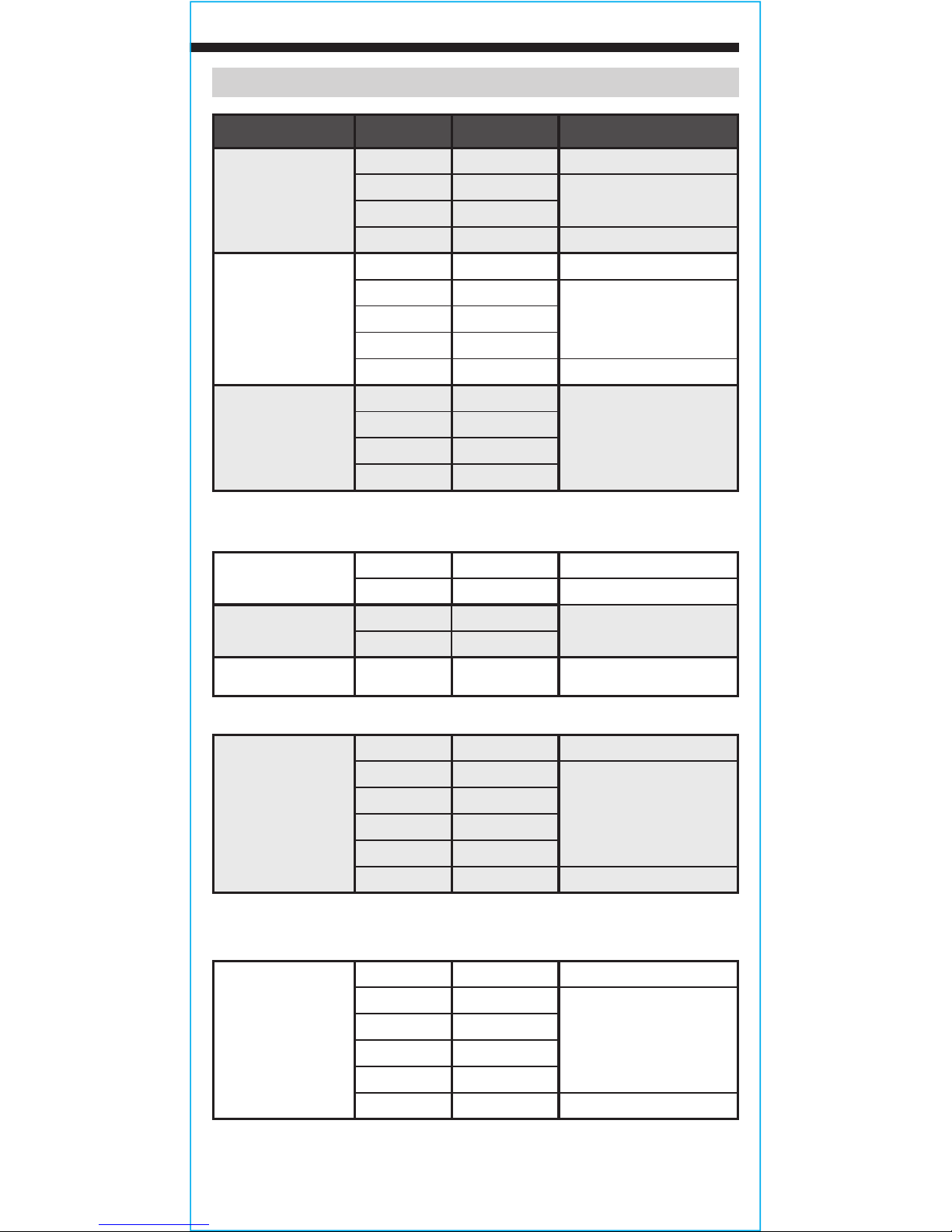
ELECTRICAL SPECIFICATIONS
Function Range Resolution Accuracy (50/60 Hz)
AC Voltage
(V AC)
6.000V 1mV ±(1.5% + 5 digits)
60.00V 10mV
±(1.2% + 5 digits)
600.0V 100mV
1000V 1V ±(1.7% + 5 digits)
DC Voltage
(V DC)
600mV 0.1mV ±(1.0% + 8 digits)
6.000V 1mV
±(0.8% + 3 digits)60.00V 10mV
600.0V 100mV
1000V 1V ±(1.2% + 3 digits)
AC + DC
Voltage
(V)
6.000V 1mV
±(2% + 6 digits)
60.00V 10mV
600.0V 100mV
1000V 1V
Input Impedance: ≥
10MΩ
Frequency Range:
45 to 400Hz (AC only)
Maximum Input: 1000V AC RMS or 1000V DC
AC Current
(A AC)
60.00A 10mA ±(2.5% + 10 digits)
600.0A 100mA ±(2.0% + 10 digits)
AC Current (A)
Inrush
60.00A 10mA
±(10.0% + 10 digits)
600.0A 100mA
DC Current (µA) 200µA 1µA ±(0.9% + 6 digits)
Frequency Range: 50 to 60Hz (AC only)
Resistance
600.0Ω 0.1Ω ±(1.2% + 5 digits)
6.000KΩ 1Ω
±(1.2% + 3 digits)
60.00kΩ 10Ω
600.0kΩ 100Ω
6.000MΩ 1kΩ
60.00MΩ 10kΩ ±(2.0% + 5 digits)
Maximum Input: 600V AC RMS or 600V DC
Capacitance
60.00nF 0.010nF ±(4.0% + 25 digits)
600.0nF 0.1nF
±(4.0% + 8 digits)
6.000µF 0.001µF
60.00µF 0.01µF
600.0µF 0.1µF
6000µF 1µF ±(10.0% + 9 digits)
Maximum Input: 600V AC RMS or 600V DC
Page 4

4
ENGLISH
WARNINGS
To ensure safe operation and service of the meter, follow these instructions.
Failure to observe these warnings can result in severe injury or death.
• Before each use verify meter operation by measuring a known voltage
or current.
• Never use the meter on a circuit with voltages that exceed the
category based rating of this meter.
• Do not use the meter during electrical storms or in wet weather.
• Do not use the meter or test leads if they appear to be damaged.
• Use only with CAT IV rated test leads.
• Ensure meter leads are fully seated, and keep fingers away from the
metal probe contacts when making measurements.
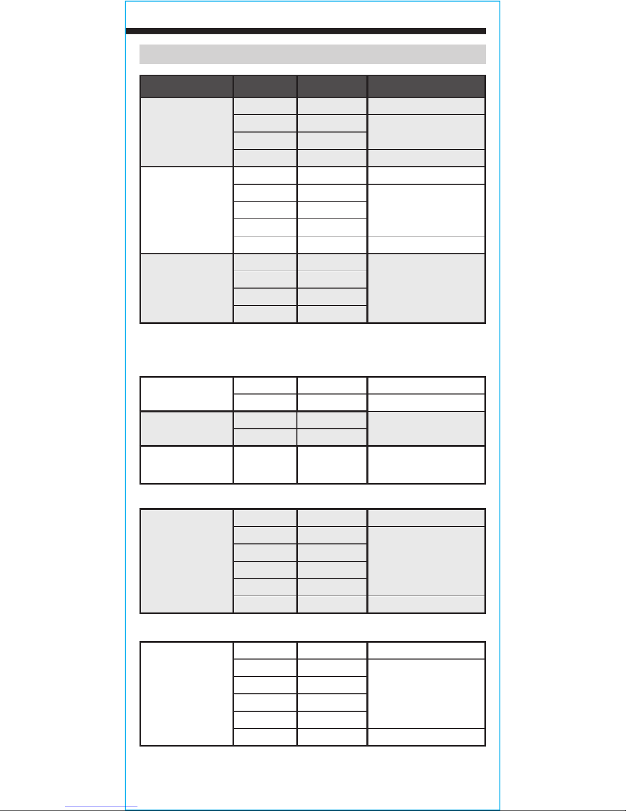
ELECTRICAL SPECIFICATIONS
Function Range Resolution Accuracy
Temperature
(Fahrenheit)
-40° to 32°F
0.1
°F
±(2.0% + 6°F)
33° to 932°F
±(1.0% + 2°F)
933° to 1832°F
1
°F
±(1.5% + 6°F)
Temperature
(Celsius)
-40° to 0°C
0.1
°C
±(2.0% + 3°C)
1° to 500°C
±(1.0% + 1°C)
501° to 1000°C
1
°C
±(1.5% + 3°C)
FREQUENCY (AUTO-RANGING)
99.99Hz 0.01Hz
±(1.0% + 5 digits)
999.9Hz 0.1Hz
9.999kHz 1Hz
99.99kHz 10Hz
999.9kHz 100Hz
Measurement Range: 10Hz – 1MHz
≤100kHz – 250mV rms ≤Input amplitude ≤20V rms
>100kHz – 1MHz: 600mV rms ≤Input amplitude ≤20V rms
DUTY CYCLE
0.1% to 99.9%
0.1% Reference only
Frequency width: ≤100kHz
OTHER MEASUREMENT APPLICATIONS
• Diode Test: Max. 1.0mA, open circuit voltage ~ 2.5V DC
• Continuity Check: Test current 0.5mA
• Low Impedance (Low Z): Input impedance: >3kΩ
Max input: 1000V RMS
• Auto Power off: After ~10 minutes of inactivity
• Overload:
"OL" indicated on display, overload protection
1000V in Voltage setting, 600V RMS in all other settings
• Polarity: "-" on display indicates negative polarity
• Display: 3-5/6 digit, 6000 Count LCD
Page 5
5
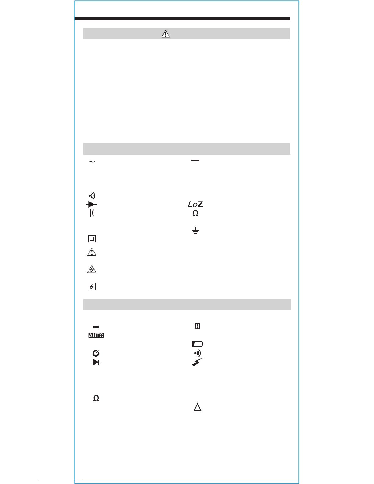
SYMBOLS ON METER
Alternating Current (AC) Direct Current (DC)
A
Amperage
V
Voltage
µA
Micro Amps
Hz
Frequency
°
F
Degrees Fahrenheit
°
C
Degrees Celsius
Audible Continuity
%
Duty-Cycle
Diode Test Low Impedance
Capacitance Resistance (Ohms)
+ Positive – Negative
COM
Common Ground
Double Insulated Class II
Warning or Caution:
To ensure safe operation and service of this meter,
follow all warnings and instructions detailed in this manual.
Risk of Electrical Shock:
I
mproper use of this meter can lead to risk of
electrical shock. Follow all warnings and instructions detailed in this manual.
Risk of Electrical Shock:
Application around and removal from
UNINSULATED HAZARDOUS LIVE conductors is permitted.
SYMBOLS ON LCD
AC
AC Measurement DC DC Measurement
Negative Reading Data Hold
Auto Ranging
MAX
Maximum Value Hold
MIN
Minimum Value Hold Low Battery
Auto Power Off Audible Continuity
Diode Test High Voltage
k
kilo (value x 103)
m
mili (value x 10-3)
M
Mega (value x 106)
n
nano (value x 10-9)
μ
micro (value x 10-6)
V
Volts
Ohms
F
Farads
A
Amps Relative Mode
LoZ
Low Impedance
%
Duty Cycle
Hz
Frequency (Hertz)
°
C
Degrees (Celsius)
°
F
Degrees (Fahrenheit)
INRUSH
Inrush Current
LPF
Low-Pass Filter
T1
T1 Temperature
T2
T2 Temperature
T-CAL
Temperature Calibration
T1-T2
Differential Temperature
AVG
Average
AC+DC
AC Voltage + DC Voltage
WARNINGS
• Use caution when working with voltages above 25V AC RMS or
60V DC. Such voltages pose a shock hazard.
• To avoid false readings that can lead to electrical shock, replace
batteries when a low battery indicator appears.
• Do not attempt to measure resistance or continuity on a live circuit.
• Always adhere to local and national safety codes. Use personal
protective equipment to prevent shock and arc blast injury where
hazardous live conductors are exposed.
• Do not attempt to measure voltages greater than 600V in LoZ setting.
• To avoid risk of electric shock, disconnect leads from any voltage
source before removing battery door.
• To avoid risk of electric shock, do not operate meter while battery
door is removed.
Page 6

6
ENGLISH
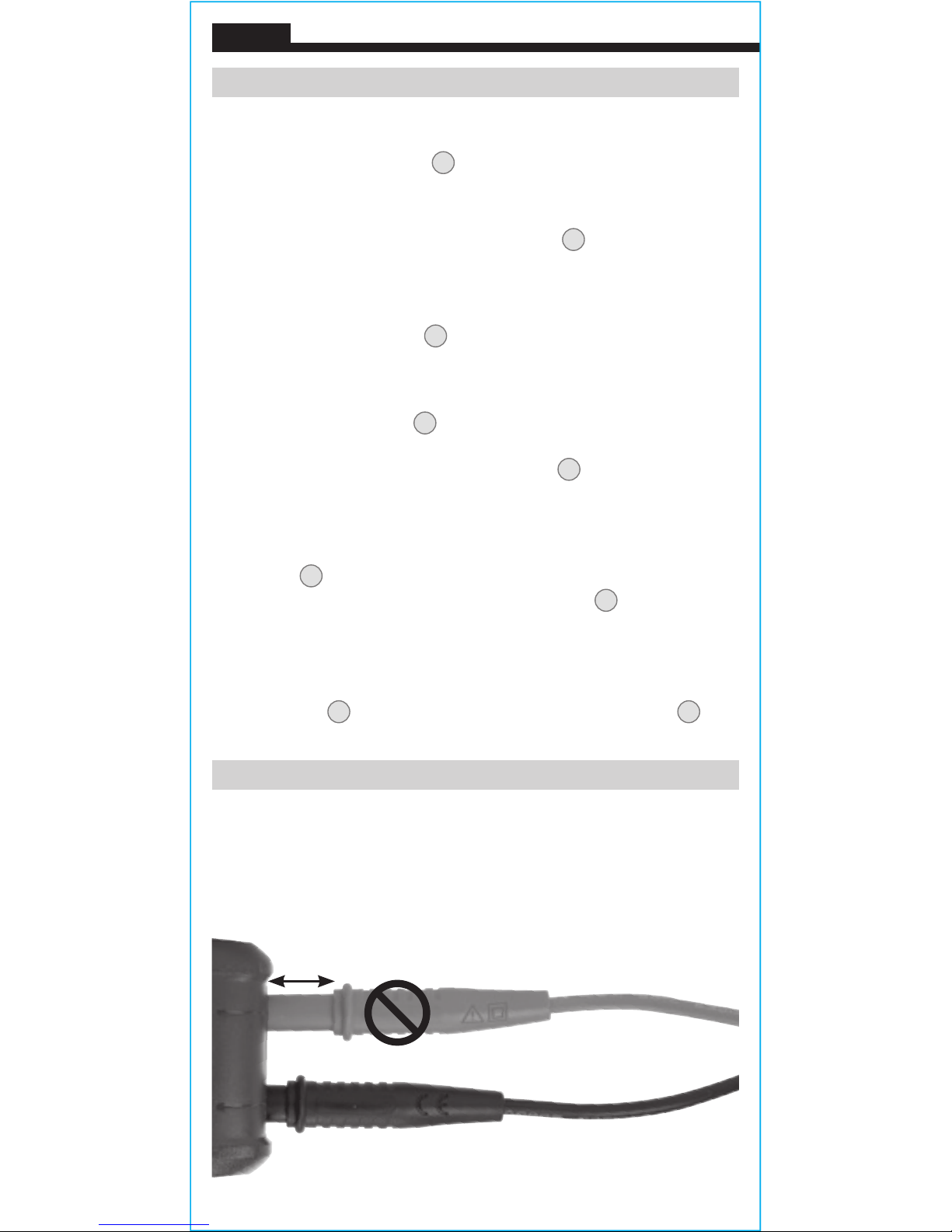
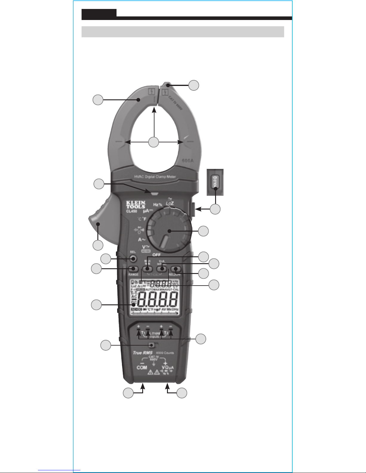
FEATURE DETAILS
NOTE: There are no user-serviceable
parts inside meter.
1.
6000 count
LCD display
2.
Function
selector
switch
3.
Clamp
4.
"COM" jack
5.
"VΩ" jack
6.
Data Hold /
Backlight
button
7.
"RANGE"
button
8.
"MAX/MIN"
button
9.
SEL (select)
button
10.
V+A /
Inrush Current
button
11.
Relative /
Low-Pass Filter
button
12.
Temperature
Calibration
buttons
13.
Clamp trigger
(press to open
clamp)
14.
Arrow markings
15.
N
on-contact
Voltage Testing
Indicator
16.
Non-Contact
Voltage Testing
Sensor
17.
K-Type
temperature
probe inputs
18.
Temperature
probe input
switch
1
9
7
3
13
10
16
15
54
8
11
6
14
12
17
18
2
Page 7

7
FUNCTION BUTTONS
ON/OFF
To power ON the meter, rotate the Function Selector switch
2
from
the OFF setting to any measurement setting. To power OFF the meter,
rotate the Function Selector switch 2 to the OFF setting. By default,
the meter will automatically power OFF after 10 minutes of inactivity.
To deactivate the power OFF functionality press and hold the SEL
button 9 before powering ON from the OFF setting. When auto
power OFF is deactivated, the Auto Power Off icon will not be
visible in the display.
SEL (SELECT) BUTTON (FOR SECONDARY FUNCTIONS)
The SEL button 9 activates the secondary function for each
application accessible by the function selector switch 2:
• In Voltage
V /
and Low Impedance modes, it toggles
between AC and DC measurements.
• In Temperature
mode, it toggles between
°F (Fahrenheit) and
°C (Celsius) measurements.
• In Continuity/Resistance/Capacitance/Diode-Test
mode, it
toggles through these measurements in order
.
The default function for each application is printed on the meter in
white, the secondary functions in orange. An icon on the LCD display
will indicate which function is active.
DATA HOLD
Press the Data Hold / Backlight button
6
to hold the measurement
on the display. Press again to release the display to return to live
measuring.
BACKLIGHT
Press and hold the Data Hold / Backlight button 6 for more than 2
seconds to turn ON the backlight. Repeat process to turn OFF.
RANGE
The meter defaults to auto-ranging mode . This mode
automatically determines the most appropriate measurement range
for the testing that is being conducted. To manually force the meter to
measure in a different range, use the Range button 7.
1. Press the "RANGE" button 7 to manually select measurement
range ( is deactivated on the LCD). Repeatedly press the
"RANGE" button 7 to cycle through the available ranges, stopping
once the desired range is reached.
2. To return to auto-ranging mode, press and hold the "RANGE"
button 7 for more than one second ( is reactivated).
Page 8
8
ENGLISH
FUNCTION BUTTONS
MAX/MIN
When the "MAX/MIN" button 8 is pressed, the meter keeps track of
the Maximum, Minimum and Average values as the meter continues
to take samples.
1. When measuring, press "MAX/MIN" button 8 to toggle between
the Maximum value (MAX), Minimum value (MIN) and Average
value (AVG). If a new Maximum, Minimum or Average occurs, the
display will update with the new value.
2. Press "MAX/MIN" button 8 for more than one second to return to
normal measuring mode.
RELATIVE MODE
When the REL/LPF button
11
is pressed, the meter will show the
relative value on the main display and real time measurement on the
secondary display. Press the REL/LPF button
11
to return to normal
measuring mode.
LOW-PASS FREQUENCY MODE
For voltage readings of high frequency motors, long press the REL/
LPF button
11
and meter will apply a low pass filter to ensure a more
accurate reading. Long press the REL/LPF button
11
to return to
normal measuring mode.
NON-CONTACT VOLTAGE TESTING
Approach the conductor under test leading with the non-contact
voltage sensor
16
. The meter delivers visual warning signals 15
when AC voltage is detected by the non-contact voltage sensor.
OPERATING INSTRUCTIONS
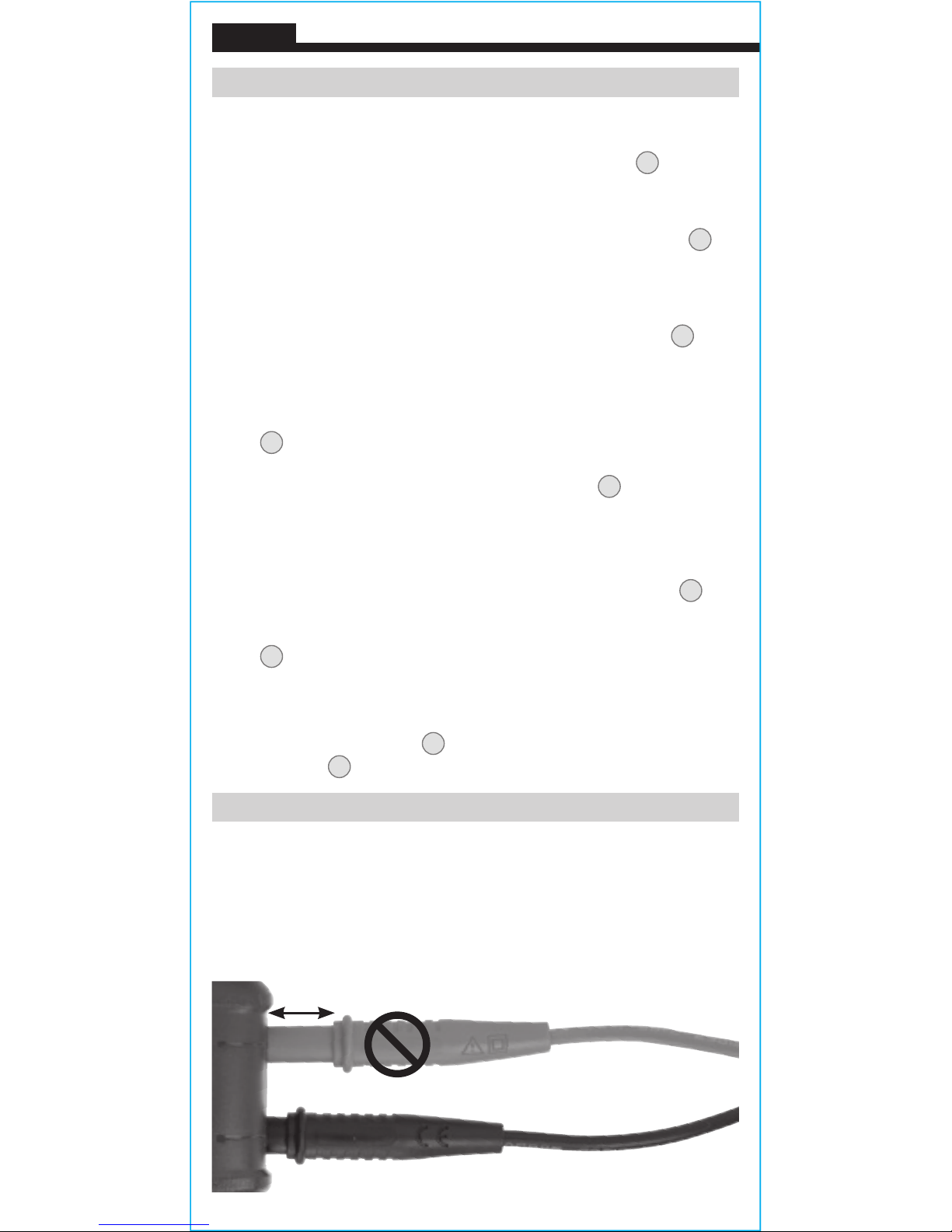
CONNECTING TEST LEADS
Do not test if leads are improperly seated. Results could cause
intermittent display readings. To ensure proper connection, firmly
press leads into the input jack completely.
INCORRECT
CORRECT
Page 9

9
OPERATING INSTRUCTIONS
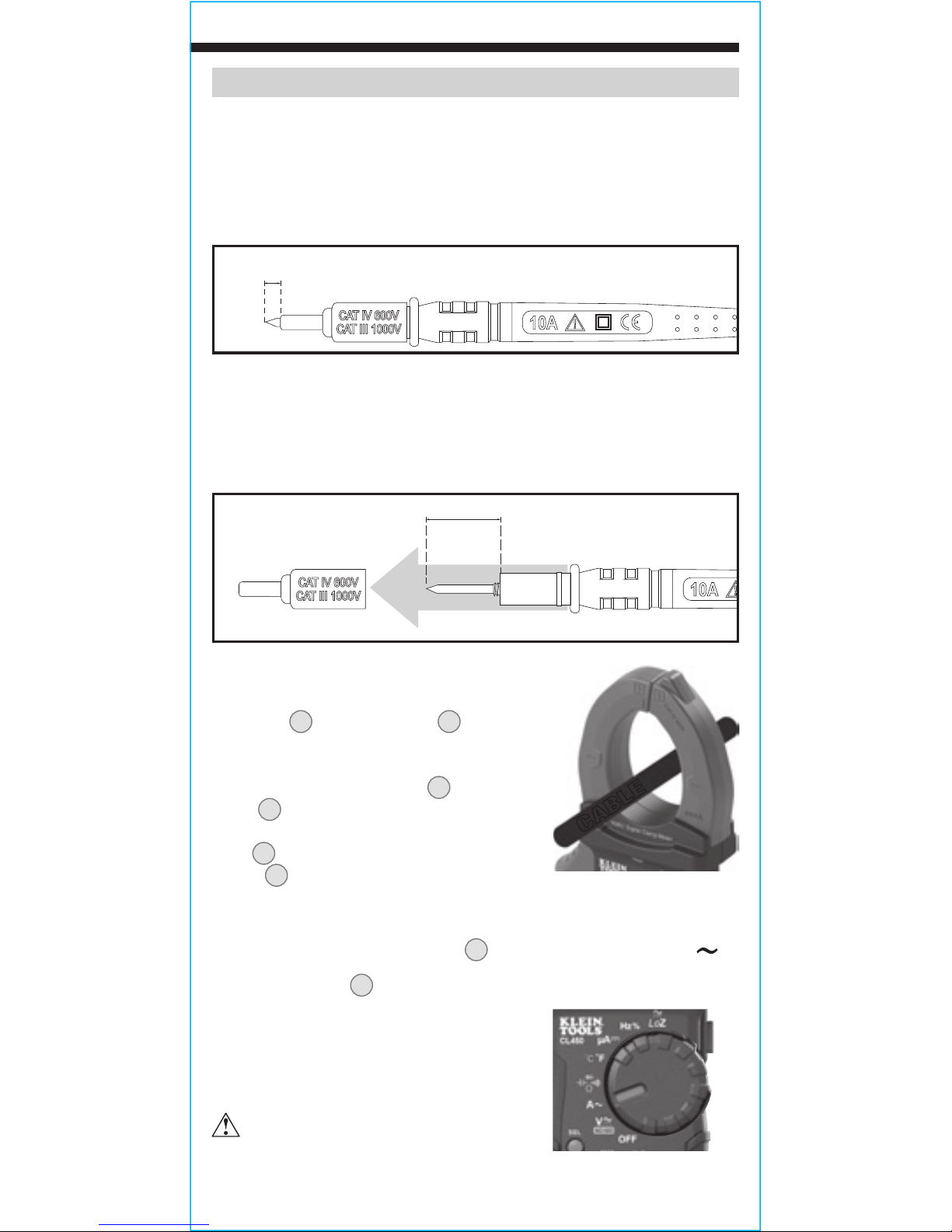
TESTING IN CAT III / CAT IV MEASUREMENT LOCATIONS
Ensure the test lead shield is pressed firmly in place. Failure to use
the CATIII / CATIV shield increases arc-flash risk.
TESTING IN CAT II MEASUREMENT LOCATIONS
CAT III / CAT IV shields may be removed for CAT II locations. This
will allow testing on recessed conductors such as standard wall
outlets. Take care not to lose the shields.
AC CURRENT (LESS THAN 600A)
AC Current is measured by pressing the
clamp trigger
13
to open the clamp 3 and
placing it around a current-carrying wire.
When measuring, care should be taken to
ensure that the clamp 3 is completely
closed with trigger 13 fully released, and
that the wire passes perpendicularly through
the center of the clamp 3 in line with the
arrow markings 14.
To measure current:
1. Rotate the Function Selector switch 2 to the AC current A setting.
2. Place clamp
3
around wire. The current measurement will be
shown in the display.
The meter will auto-range to display the
measurement in the most appropriate
range.
Disconnect test leads when
measuring with the clamp.
5/32"
(4 mm)
.7" (18 mm)
WIRE
Page 10

10
ENGLISH
OPERATING INSTRUCTIONS
INRUSH CURRENT
The Inrush feature captures starting current of a compressor motor.
Starting current can assist in diagnosing a motor before it fails.
To measure inrush current:
1. Rotate the Function Selector switch 2 to
the AC current A setting.
2. Place clamp
3
around wire. The
current measurement will be shown in
the display.
3. Long press the V+A/Inrush button
10
for 2 seconds to enter the Inrush mode and manually select 60A
or 600A range by pressing the RANGE button
7. Place the clamp
around the compressor start wire and turn motor on. The starting
current will hold on the main display. The Inrush measurement
period is 100-miliseconds.
4. Long press V+A/Inrush button
10 for 2 seconds to exit.
MICROAMPS DC CURRENT
Microamps DC is applied to a flame rectifier diode test on a heater
control.
1. Rotate the Function Selector switch 2
to the µA setting.
2. Connect the leads between flame sensor
probe and control module and turn on
heating unit.
3. The current measurement will be
shown in the main display.
NOTE: When the flame is on, there should be a measureable µA
DC signal, typically under 10 μA DC. Compare measurement to
manufacturer’s specifications.
Page 11
11
OPERATING INSTRUCTIONS
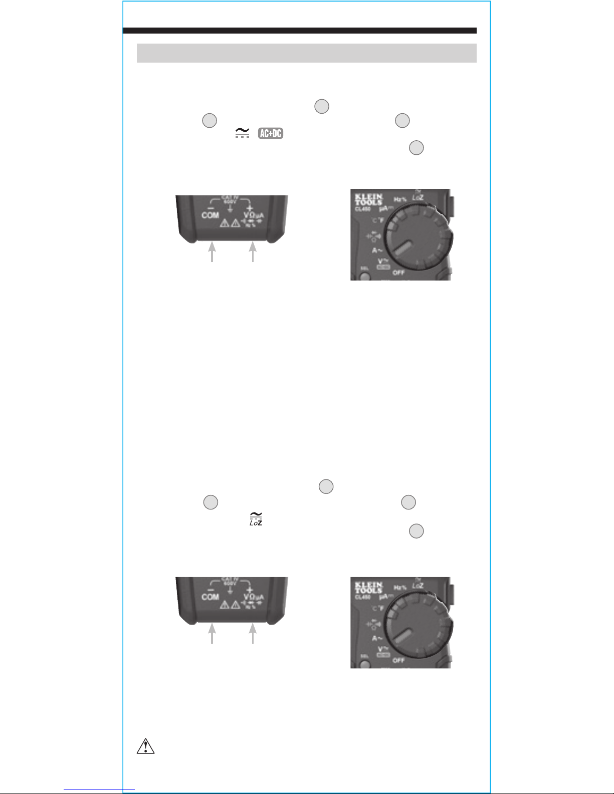
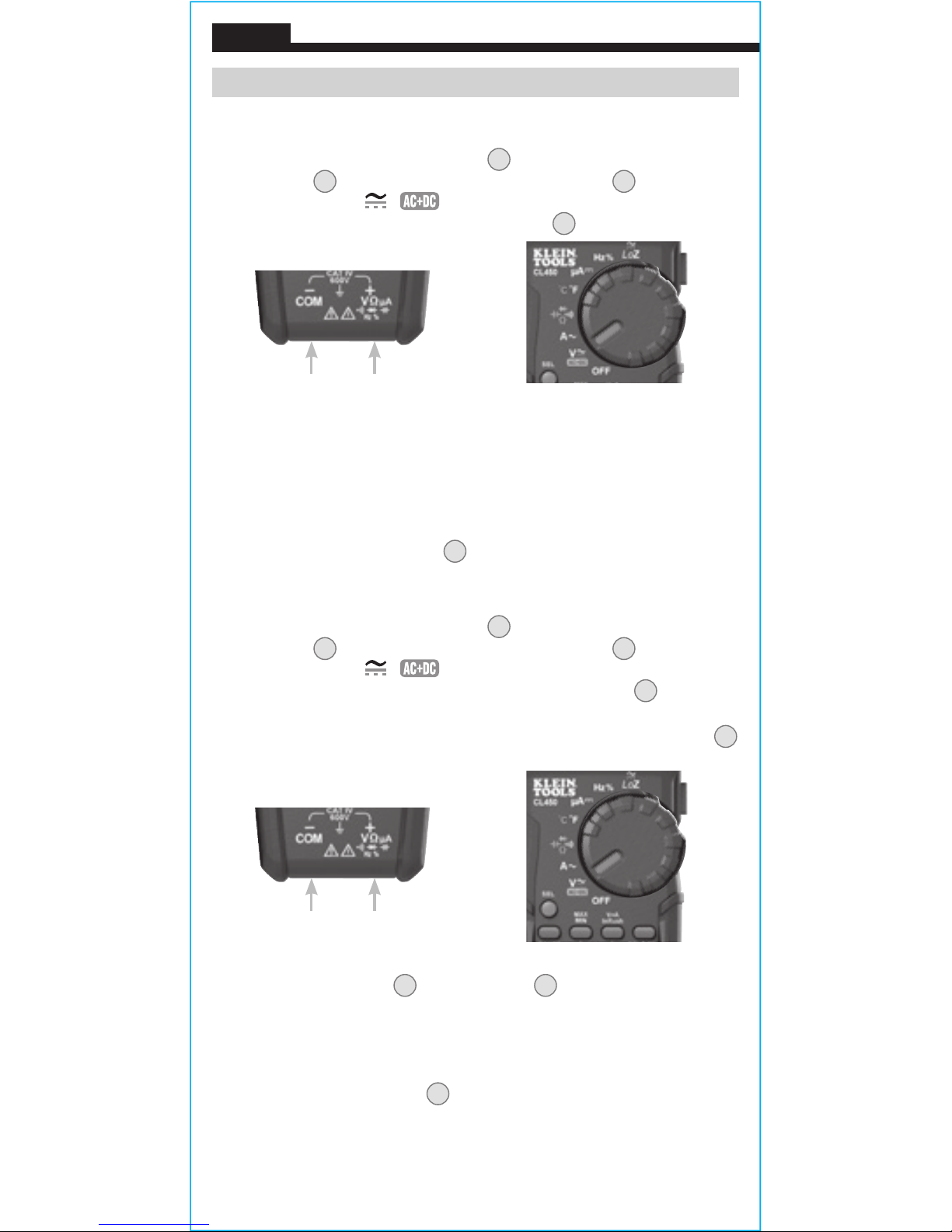
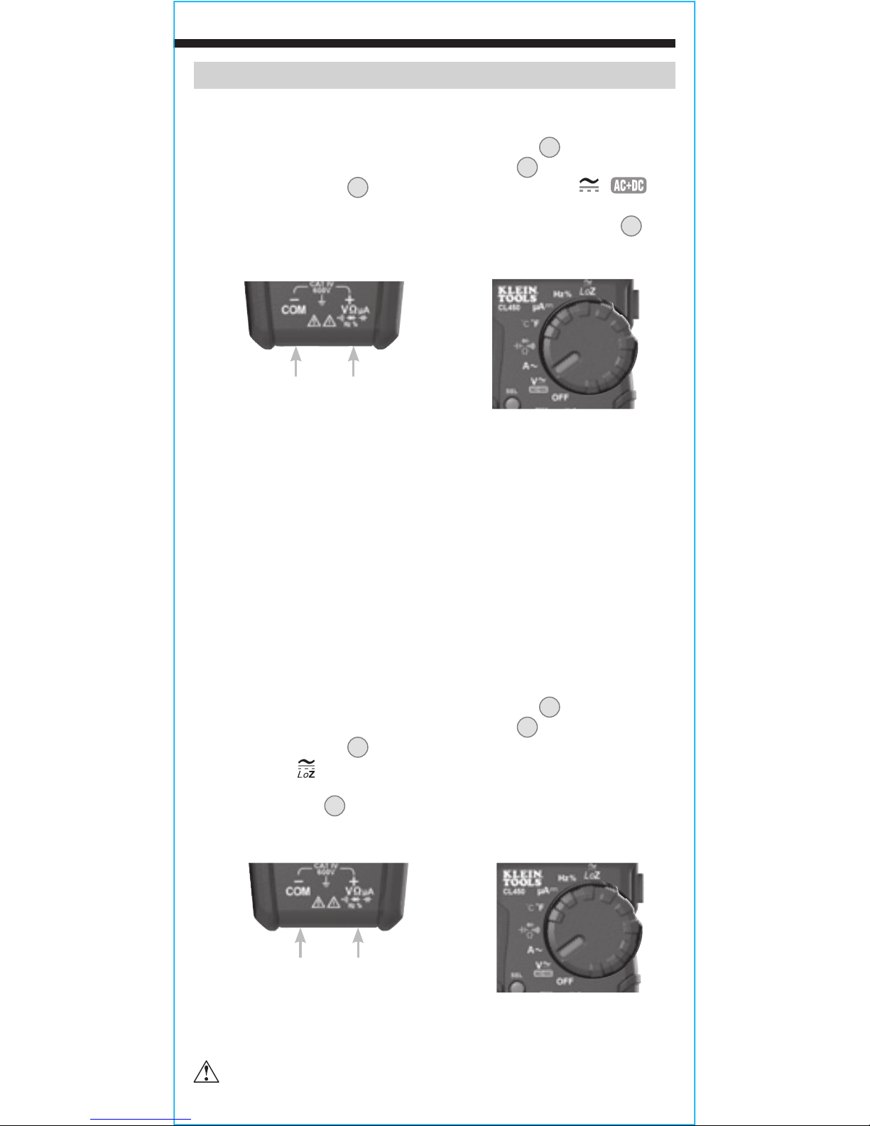
AC/DC VOLTAGE (LESS THAN 1000V)
1. Insert RED test lead into VΩ jack 5, and BLACK test lead into
COM jack 4, and rotate function selector switch 2 to the
AC/DC voltage
V
/
setting.
The meter defaults to AC
measurement.
To measure DC, press the SEL button 9 to toggle
between AC and DC modes. The AC or DC icon on the LCD
indicates which mode is selected.
2. Apply test leads to the circuit to be tested to measure voltage.
The meter will auto-range to display the measurement in the
most appropriate range.
NOTE: If "–" appears on the LCD, the test leads are being applied to
the circuit in reverse. Swap the position of the leads to correct this.
NOTE: When in a voltage setting and the test leads are open,
readings of order mV may appear on the display. This is noise and
is normal. By touching the test leads together to close the circuit
the meter will measure zero volts.
AC/DC LoZ VOLTAGE (LESS THAN 600V)
1. Insert RED test lead into VΩ jack
5
, and BLACK test lead into
COM jack
4
, and rotate function selector switch 2 to the
AC/DC LoZ voltage setting.
The meter defaults to AC
measurement.
To measure DC, press the SEL button 9 to toggle
between AC and DC modes. The AC or DC icon on the LCD
indicates which mode is selected. Note "AC" or "DC" on the display.
2. Apply test leads to the circuit to be tested to measure voltage.
The meter will auto-range to display the measurement in the
most appropriate range.
Do not attempt to measure voltages greater than 600V
in LoZ setting.
Black lead Red lead
Black lead Red lead
Page 12
12
OPERATING INSTRUCTIONS
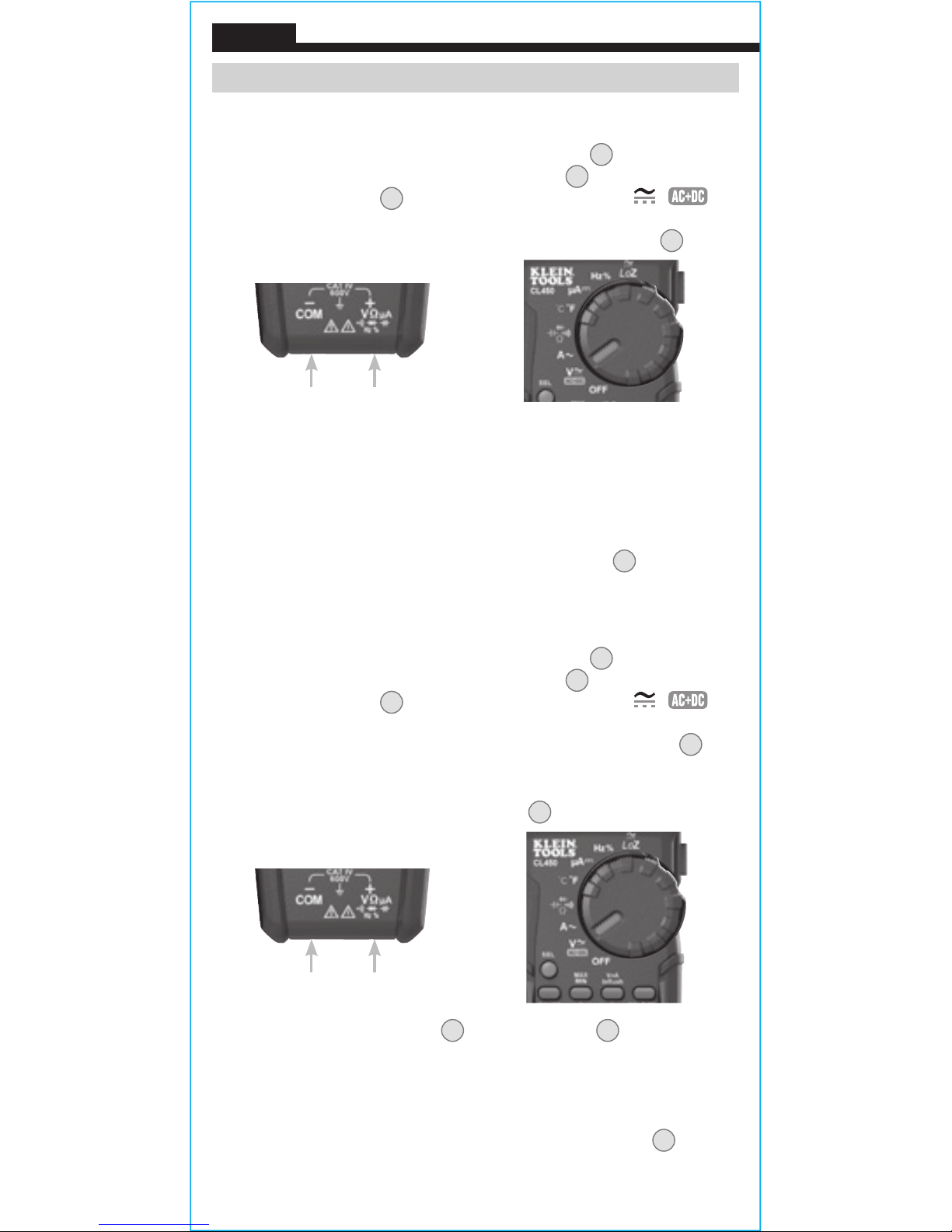
AC VOLTAGE + DC VOLTAGE FUNCTION
1. Insert RED test lead into VΩ jack 5, and BLACK test lead into
COM jack 4, and rotate function selector switch 2 to the
AC/DC voltage
V
/
setting.
The meter defaults to AC
measurement.
Long press the SEL button 9 to enter the
ACV + DCV mode.
2. Apply test leads to the circuit to be tested to measure voltage.
The meter will auto-range to display the measurement in the
most appropriate range. The ACV + DCV measurement will
be in the main display, and the secondary display will have the
individual voltages that toggle between the AC and DC voltages.
3. Long press the SEL button 9 to exit the mode.
AC VOLTAGE + AC AMPERAGE FUNCTION
1. Insert RED test lead into VΩ jack
5
, and BLACK test lead into
COM jack 4, and rotate function selector switch 2 to the
AC/DC voltage
V
/
setting.
The meter defaults to AC
measurement.
To measure DC, press the SEL button 9 to toggle
between AC and DC modes. The AC or DC icon on the LCD
indicates which mode is selected. Press the
V+A/Inrush button
10
to enter the ACV + ACA mode.
2. Press clamp trigger
13
to open clamp 3 and place around
current-carrying wire.
3. The main display will show AC Voltage and the secondary
display will show AC Amperage.
4. Press V+A/Inrush button
10 to exit.
ENGLISH
Black lead Red lead
Black lead Red lead
Page 13
13
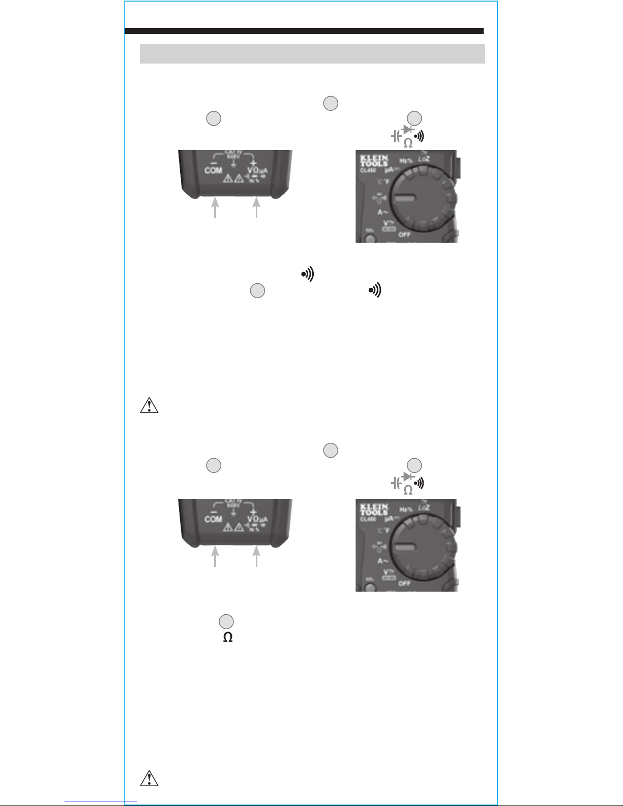
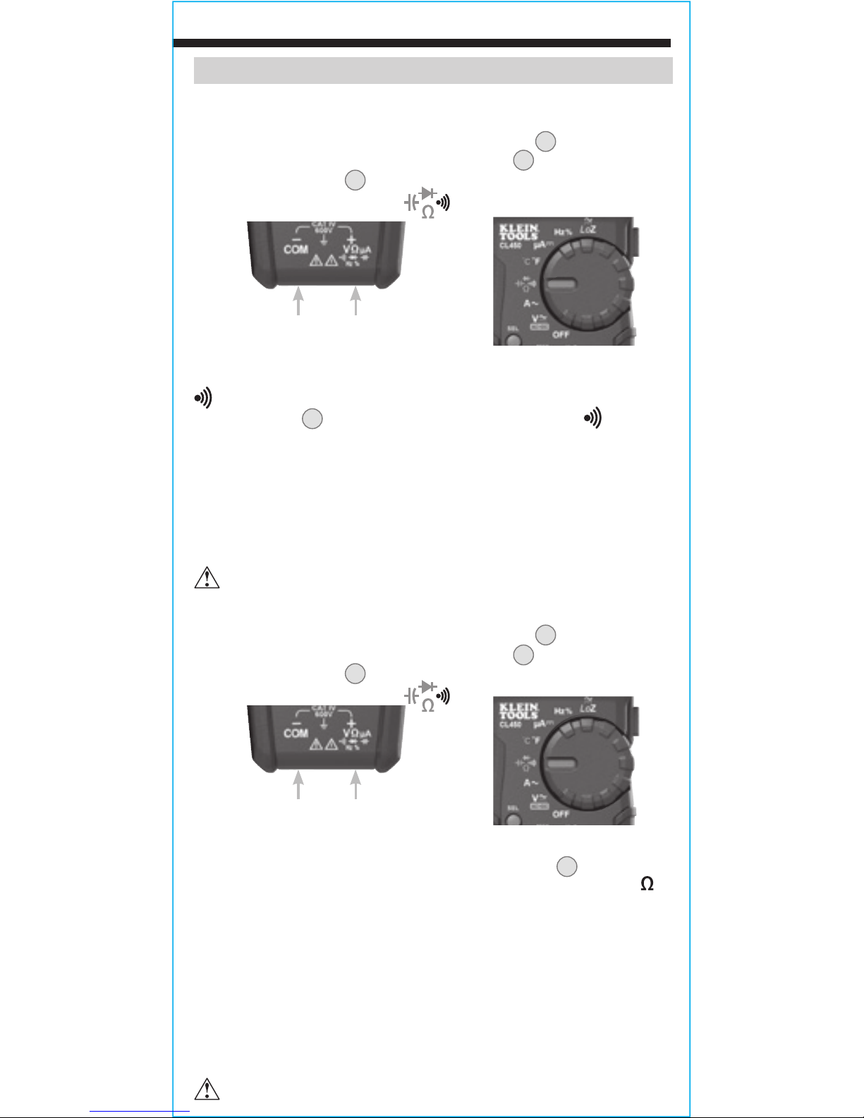
RESISTANCE MEASUREMENTS
1. Insert RED test lead into VΩ jack
5
, and BLACK test lead into
COM jack
4
, and rotate function selector switch 2 to the
Continuity/Resistance/Capacitance/Diode-Test
setting.
NOTE: The meter defaults to Continuity testing in this mode. Press
the SEL button
9
once to enter Resistance testing mode. The
Resistance icon
will appear on the display.
2. Remove power from circuit.
3. Measure resistance by connecting test leads to circuit. The
meter will auto-range to display the measurement in the most
appropriate range.
NOTE: When in a Resistance setting and the test leads are open
(not connected across a resistor), or when a failed resistor is under
test, the display will indicate O.L. This is normal.
DO NOT attempt to measure resistance on a live circuit.
CONTINUITY
1. Insert RED test lead into VΩ jack
5
, and BLACK test lead into
COM jack
4
, and rotate function selector switch 2 to the
Continuity/Resistance/Capacitance/Diode-Test
setting.
NOTE: The meter defaults to Continuity testing in this mode. Ensure
that the Continuity Testing icon
is visible on the display. If not,
press the SEL button
9
repeatedly until the icon is shown.
2. Remove power from circuit.
3. Test for continuity by connecting conductor or circuit with test
leads. If resistance is measured less than 10Ω, an audible signal
will sound and display will show a resistance value indicating
continuity. If circuit is open, display will show "OL".
DO NOT attempt to measure continuity on a live circuit.
OPERATING INSTRUCTIONS
Black lead Red lead
Black lead Red lead
Page 14
14
ENGLISH
OPERATING INSTRUCTIONS
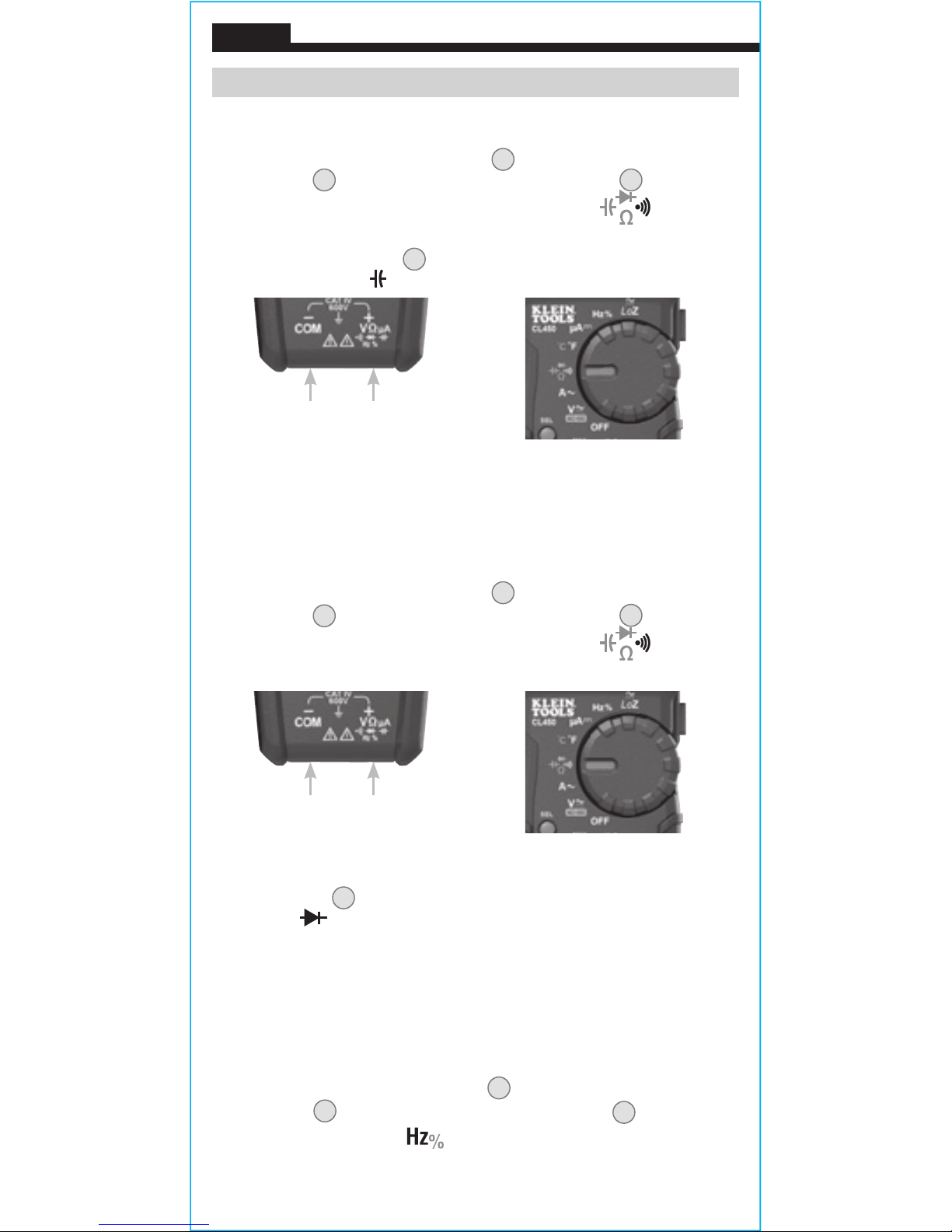
CAPACITANCE
1. Insert RED test lead into VΩ jack 5, and BLACK test lead into
COM jack 4, and rotate function selector switch 2 to the
Continuity/Resistance/ Capacitance/Diode-Test
setting.
2.
NOTE: The meter defaults to Continuity testing in this mode.
Press the SEL button 9 twice to enter capacitance mode. The
Capacitance icon will appear on the display.
3. Remove power from circuit.
4. Measure capacitance by connecting test leads across the capacitor.
The meter will auto-range to display the measurement in the most
appropriate range.
DIODE TEST
1. Insert RED test lead into VΩ jack
5
, and BLACK test lead into
COM jack
4
, and rotate function selector switch 2 to the
Continuity/Resistance/ Capacitance/Diode-Test
setting.
NOTE: The meter defaults to Continuity testing in this mode. Press
the SEL button 9 three times to enter Diode testing mode. The
Diode icon will appear on the display.
2. Touch test leads to diode. A reading of 200-800mV on display
indicates forward bias, "OL" indicates reverse bias. An open
device will show "OL" in both polarities. A shorted device will
show approximately 0mV.
FREQUENCY / DUTY-CYCLE
1. Insert RED test lead into VΩ jack
5
and BLACK test lead into
COM jack
4
, and rotate function selector switch 2 to the
Frequency/Duty-Cycle
setting.
Black lead Red lead
Black lead Red lead
Page 15

15
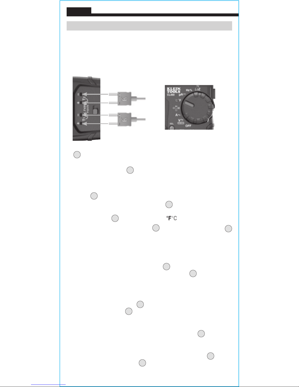
TEMPERATURE
1. Remove leads from meter and slide the temperature probe input
switch 18 to close jacks and expose the K-Type thermocouple
ports.
2. Insert K-type thermocouple into port T1 17 (observe polarity
markings on thermocouple and meter), and rotate function
selector switch 2 to the Temperature setting.
NOTE: The meter defaults to Fahrenheit scale in this mode. To
enter Celsius scale, long-press the SEL button 9. Ensure that the
appropriate icon (either °F or °C) appears on the display.
NOTE: The meter may be set to default to the Celsius scale by
powering-ON the meter from the OFF position with the Data Hold
& Backlight button
6
depressed. To re-set the default to the
Fahrenheit scale repeat the power-ON sequence.
3. To measure temperature, make contact between the
thermocouple tip and the object being measured. When
thermocouple tip and object are in thermal equilibrium, the
measurement on the display will stabilize. The meter will autorange to display the measurement in the most appropriate range.
Remove thermocouple before switching meter to other
measurement functions.
T
he thermocouple included with the original purchase
is suitable for temperatures below 356°F / 180°C only.
To measure higher temperatures, a K-type thermocouple
with the appropriate measurement range should be used.
NOTE: The main display shows Frequency and the secondary display
shows Duty-Cycle.
2. Measure by connecting test leads across the circuit.
OPERATING INSTRUCTIONS
Black lead Red lead
K-Type Thermocouple
Page 16
16
OPERATING INSTRUCTIONS
DIFFERENTIAL TEMPERATURE
1. When two K-Type thermocouples are attached to the meter,
the main display will show T1 temperature and the secondary
display will show T2 temperature. Insert one K-type thermo
couple into port T1 and another into port T2.
2. To measure the differential temperature press the "SEL" button
9
and the T1-T2 icon will be displayed. The main display will
show the differential temperature value.
3. Press the SEL button
9
again to exit differential temperature.
TEMPERATURE CALIBRATION
1. Remove leads from meter and slide the temperature probe input
switch 18 to close jacks and expose the K-Type thermocouple ports.
2. Insert K-type thermocouple into ports 17 (observe polarity
markings on thermocouple and meter), and rotate function
selector switch
2
to the Temperature setting.
3. Long press the MAX/MIN button 8 and the V+A/Inrush button
10
at the same time. The meter will beep, and the CAL icon will
appear on the secondary display and the main display will have the
temperature measurement.
NOTE: In T-CAL mode, the T1 and T2 channels can be selected for
calibration by pressing the SEL button 9, and the °F and °C units
can be changed by a long press to the SEL button 9.
4. Place the K-Type thermocouple in a known temperature system
(eg. ice water, boiling water, or other standard temperature
source) and allow to stabilize.
5. Utilize the RANGE button
7
to increase the measured value and
the REL/LPF button
11 to decrease the value. Once adjusted to
the correct value, the T-CAL icon will appear on the display and
it will remain on the screen to designate a user calibration.
NOTE: To clear calibration data, long-press the HOLD 6 button to
default to factory temperature calibration. The T-CAL icon will be
removed from the display.
6. To exit the calibration mode, long-press the MAX/MIN
8
button
and the
V+A/Inrush button 10
at the same time.
ENGLISH
K-Type Thermocouples
Page 17
17
MAINTENANCE
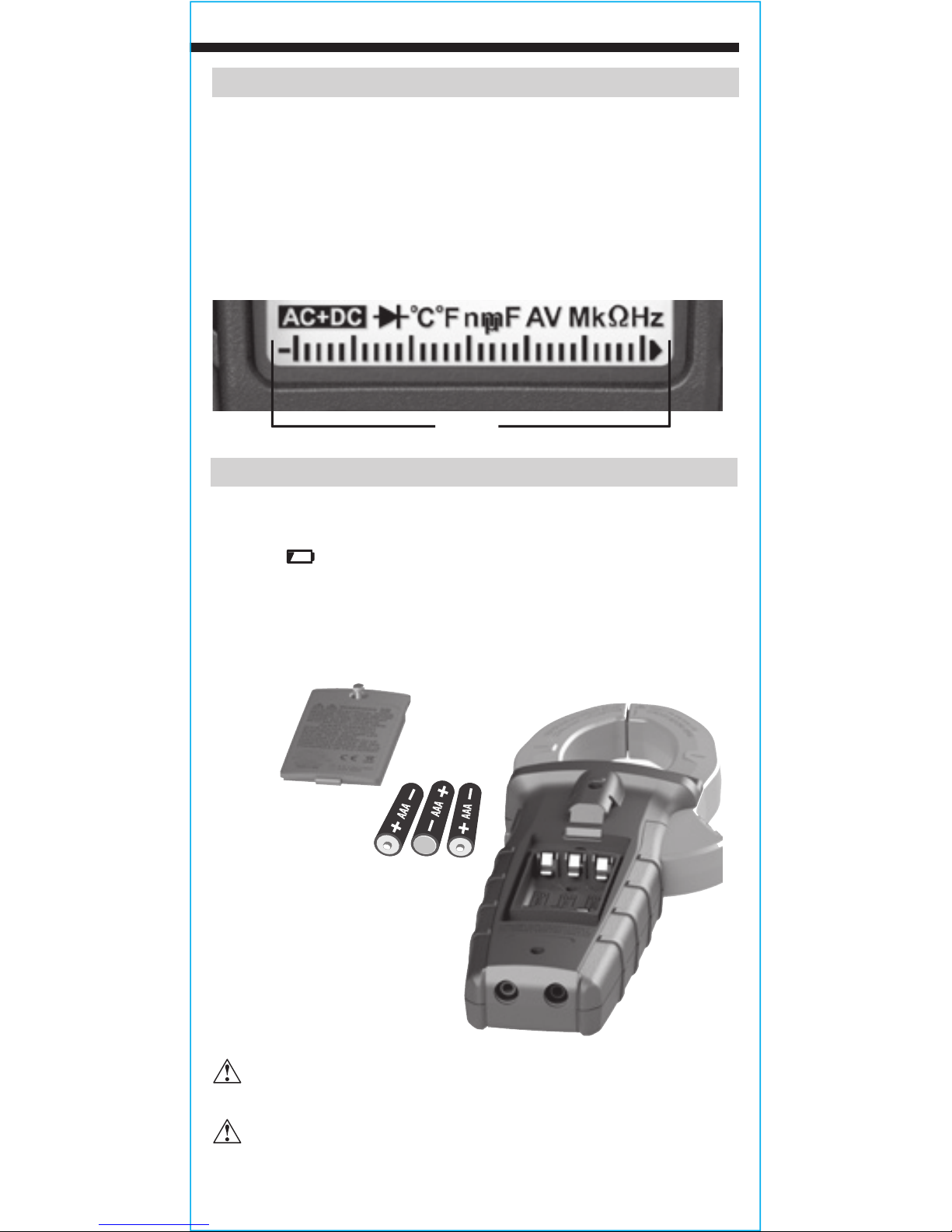
BATTERY REPLACEMENT
When the indicator is displayed, batteries must be replaced.
1. Loosen screw on battery door.
2. Replace 3 x AAA batteries (note proper polarity).
3. Replace battery door and fasten securely with screw.
T
o avoid risk of electric shock, disconnect leads from any voltage
source before removing battery door.
To avoid risk of electric shock, do not operate meter while
battery door is removed.
BAR GRAPH
The Bar Graph is an analog representation of the measurement. It responds
to the measurement approximately 3-5 times faster than the digits in the
digital display which, in certain circumstances, may allow the user to have
a clearer view of quick changes in the property being measured. In any
given range, the bar graph scales from zero on the left hand side to the
maximum value of the range on the right hand side of the display.
Bar graph
OPERATING INSTRUCTIONS
Page 18
ENGLISH
CLEANING
Be sure meter is turned off and wipe with a clean, dry lint-free
cloth.
Do not use abrasive cleaners or solvents.
STORAGE
Remove the batteries when meter is not in use for a prolonged
period of time. Do not expose to high temperatures or
humidity. After a period of storage in extreme conditions
exceeding the limits mentioned in the General Specifications
section, allow the meter to return to normal operating
conditions before using.
WARRANTY
www.kleintools.com/warranty
DISPOSAL / RECYCLE
Do not place equipment and its accessories in the trash.
Items must be properly disposed of in accordance with local
regulations. Please see www.epa.gov or www.erecycle.org
for additional information.
CUSTOMER SERVICE
KLEIN TOOLS, INC.
450 Bond Street
Lincolnshire, IL 60069
1-877-775-5346
customerservice@kleintools.com
www.kleintools.com
Page 19

ESPAÑOL
CL450
MANUAL DE INSTRUCCIONES
Multímetro de gancho
para HVAC
Ω
True RMS
Tecnología de
medición
• MICROAMPERIOS CD
• TEMPERATURA
DIFERENCIAL
• CALIBRACIÓN DE
TEMPERATURA
DIGITAL
• CORRIENTE DE
INSERCIÓN
• BAJA IMPEDANCIA
Page 20

20
ESPAÑOL
ESPECIFICACIONES GENERALES
Klein Tools CL450 es un multímetro digital de gancho de rango automático
con media cuadrática real (TRMS) que mide corriente CA y corriente de
inserción con la pinza, mide voltaje CA/CD, microamperios CD, resistencia,
continuidad, frecuencia y capacitancia, prueba diodos con cables de prueba
y mide temperatura diferencial con sondas de termopar tipo K.
• Entorno: Interiores y exteriores
• Altitud de funcionamiento: 6562pies (2000m)
• Humedad relativa: <80% sin condensación
• Temperatura de operación: 32°F a 122°F (0°C a 50°C)
• Temperatura de almacenamiento: 14°F a 122°F (-10°C a 50°C)
• Precisión: Valores establecidos según una temperatura ambiente de
65°F a 83°F (18°C a 28°C)
• Coeciente de temperatura: 0,1 × (precisión indicada) por cada
°C por encima de los 28°C o por debajo de los 18°C, es necesario
realizar correcciones si la temperatura del ambiente de trabajo se
encuentra fuera del rango de precisión de temperatura
• Baterías: 3 AAA de 1,5V
• Dimensiones: 10,04" × 3,77" × 1,59" (255mm × 96mm × 40mm)
• Peso: 13,6 oz (386 g) incluidas las baterías
• Calibración: Precisa durante un año
• Normas: Cumple con las normas UL 61010-1, 61010-2-032
y 61010-2-033.
Certificado según las normas CSA STD C22.2 No. 61010-1,
61010-2-032 y 61010-2-033.
IEC/EN 61010-1, 61010-2-032,
61010-2-033, 61326-1.
• Grado de contaminación: 2
• Precisión: ± (% de lectura + cantidad de dígitos menos significativos)
• Protección ante caídas: 6,6pies (2m)
• Clasicación de seguridad: CATIV 600V, doble aislamiento
CATIV: La categoría IV de medición es aplicable a los circuitos de
medición y prueba conectados a la fuente de la instalación de red de
bajo voltaje de un edificio.
• Entorno electromagnético: IEC/EN 61326-1. Este equipo cumple con
los requisitos apropiados para su uso en entornos electromagnéticos
básicos y controlados, como propiedades residenciales,
establecimientos comerciales e instalaciones de industria ligera.
Especificaciones sujetas a cambios.
Page 21

21
ESPECIFICACIONES ELÉCTRICAS
Función Rango Resolución Precisión
(50Hz/60Hz)
Voltaje CA
(V CA)
6,000V 1mV ± (1,5% + 5 dígitos)
60,00V 10mV
± (1,2% + 5 dígitos)
600,0V 100mV
1000V 1V ± (1,7% + 5 dígitos)
Voltaje CD
(V CD)
600mV 0,1mV ± (1,0% + 8 dígitos)
6,000V 1mV
± (0,8% + 3 dígitos)60,00V 10mV
600,0V 100mV
1000V 1V ± (1,2% + 3 dígitos)
Voltaje CA + CD
(V)
6,000V 1mV
± (2% + 6 dígitos)
60,00V 10mV
600,0V 100mV
1000V 1V
Impedancia de entrada: ≥
10MΩ
Rango de frecuencia:
45Hz a 400Hz (solo CA)
Entrada máxima: 1000 V CA RMS o 1000 V CD
Corriente CA
(A CA)
60,00A 10mA ± (2,5% + 10 dígitos)
600,0A 100mA ± (2,0% + 10 dígitos)
Corriente de
inserción (A)
de CA
60,00A 10mA
± (10,0% + 10 dígitos)
600,0A 100mA
Corriente CD (µA)
200µA 1µA ± (0,9 % + 6 dígitos)
Intervalo de frecuencia: 50Hz a 60Hz (solo CA)
Resistencia
600,0Ω 0,1Ω ± (1,2% + 5 dígitos)
6,000kΩ 1Ω
± (1,2% + 3 dígitos)
60,00kΩ 10Ω
600,0kΩ 100Ω
6,000MΩ 1kΩ
60,00MΩ 10kΩ ± (2,0% + 5 dígitos)
Entrada máxima: 600V CA RMS o 600V CD
Capacitancia
60,00nF 0,010nF ± (4,0% + 25 dígitos)
600,0nF 0,1nF
± (4,0% + 8 dígitos)
6,000µF 0,001µF
60,00µF 0,01µF
600,0µF 0,1µF
6000µF 1µF ± (10,0% + 9 dígitos)
Entrada máxima: 600V CA RMS o 600V CD
Page 22

22
ESPAÑOL
ADVERTENCIAS
Para garantizar un funcionamiento y servicio seguros del medidor, siga
estas instrucciones. El incumplimiento de estas advertencias puede
provocar lesiones graves o la muerte.
• Antes de cada uso, verifique el funcionamiento del multímetro midiendo
un voltaje o corriente conocidos.
• Nunca debe utilizar este multímetro en un circuito con voltajes que
excedan la clasificación correspondiente a la categoría del multímetro.
• No utilice el multímetro durante tormentas eléctricas o en clima húmedo.
• No utilice el multímetro o los cables de prueba si en apariencia están dañados.
• Utilice el probador con cables de prueba con clasificación CAT IV únicamente.
• Asegúrese de que los cables del multímetro estén correctamente colocados y mantenga
los dedos lejos de los contactos de la sonda de metal al realizar las mediciones.
ESPECIFICACIONES ELÉCTRICAS
Función Rango Resolución Precisión
Temperatura
(Fahrenheit)
-40°F a 32°F
0,1
°F
± (2,0% + 6°F)
33°F a 932°F
± (1,0% + 2°F)
933°F a 1832°F
1
°F
± (1,5% + 6°F)
Temperatura
(Celsius)
-40°C a 0°C
0,1
°C
± (2,0% + 3°C)
1°C a 500°C
± (1,0% + 1°C)
501°C a 1000°C
1
°C
±(1,5% + 3°C)
FRECUENCIA (RANGO AUTOMÁTICO)
99,99Hz 0,01Hz
± (1,0% + 5dígitos)
999,9Hz 0,1Hz
9,999kHz 1Hz
99,99kHz 10Hz
999,9kHz 100Hz
Rango de medición: 10Hz a 1MHz
≤100kHz – 250mV RMS ≤amplitud de entrada ≤20V RMS
>100kHz – 1MHz: 600mV RMS ≤amplitud de entrada ≤20V RMS
CICLO DE SERVICIO
0,1% a 99,9%
0,1% Solo como referencia
Ancho de frecuencia: ≤100kHz
OTRAS APLICACIONES DE MEDICIÓN
• Prueba de diodo:
1,0mA máx., 2,5V CD de voltaje de circuito abierto aprox.
• Vericación de continuidad: 0,5mA de corriente de prueba
• Baja impedancia (Low Z): Impedancia de entrada: >3kΩ
Entrada máx.: 1000VRMS
• Apagado automático: Después de aprox. 10minutos de inactividad
• Sobrecarga:
Se indica "OL" en pantalla, protección contra sobrecarga de
1000V en posición de voltaje, 600V RMS en las demás
posiciones
• Polaridad: "-" en pantalla indica polaridad negativa
• Pantalla: LCD de 3-5/6dígitos con recuento de 6000
Page 23

23
SÍMBOLOS DEL MULTÍMETRO
Corriente alterna (CA) Corriente directa (CD)
A
Amperaje
V
Voltaje
µA
Microamperios
Hz
Frecuencia
°
F
Grados Fahrenheit
°
C
Grados Celsius
Continuidad por indicador audible
%
Ciclo de servicio
Prueba de diodo Baja impedancia
Capacitancia Resistencia (ohmios)
+ Positivo – Negativo
COM
Común
Conexión a tierra
Doble aislamiento Clase II
Advertencia o precaución:
Para garantizar un funcionamiento y servicio
seguros del multímetro, respete todas las advertencias y siga las instrucciones
descritas en este manual.
Riesgo de choque eléctrico:
El
uso incorrecto de este multímetro puede dar lugar
a riesgos de choque eléctrico. Respete todas las advertencias y siga las instrucciones
descritas en este manual.
Riesgo de choque eléctrico:
Se permite su uso alrededor de entornos de
CONDUCTORES ACTIVOS PELIGROSOS SIN AISLAMIENTO, como para el
retiro de estos.
SÍMBOLOS DE LA PANTALLA LCD
AC
Medición de CA DC Medición de CD
Lectura negativa Retención de datos
Rango automático
MAX
Retención del valor máximo
MIN
Retención del valor mínimo
Batería baja
Apagado automático
Continuidad por indicador audible
Prueba de diodo Alto voltaje
k
kilo (valor × 103)
m
mili (valor × 10-3)
M
Mega (valor × 106)
n
nano (valor × 10-9)
μ
micro (valor × 10-6)
V
Voltios
Ohmios
F
Faradios
A
Amperios Modo relativo
LoZ
Baja impedancia
%
Ciclo de servicio
Hz
Frecuencia (Hertz)
°
C
Grados (Celsius)
°
F
Grados (Fahrenheit)
INRUSH
Corriente de inserción
LPF
Filtro de paso bajo
T1
Temperatura T1
T2
Temperatura T2
T-CAL
Calibración de temperatura
T1-T2
Temperatura diferencial
AVG
Promedio
AC+DC
Voltaje CA + Voltaje CD
ADVERTENCIAS
• Proceda con precaución cuando trabaje con voltajes superiores a 25V CA RMS
o 60V CD. Esos voltajes implican un riesgo de choque eléctrico.
• Para evitar lecturas falsas que puedan provocar choque eléctrico, reemplace las
baterías cuando aparezca el indicador de batería baja.
• No intente medir resistencia o continuidad en un circuito activo.
• Cumpla siempre con los códigos de seguridad locales y nacionales. Utilice
equipo de protección personal para prevenir lesiones por choque eléctrico y arco
eléctrico en los lugares donde haya conductores activos peligrosos expuestos.
• No intente medir voltajes mayores de 600V en la posición "LoZ" (Baja impedancia).
• Para evitar el riesgo de choque eléctrico, desconecte los cables de toda fuente
de voltaje antes de retirar la tapa del compartimento de baterías.
• Para evitar riesgo de choque eléctrico, no haga funcionar el multímetro sin
colocar la tapa del compartimento de baterías.
Page 24

24
ESPAÑOL
DETALLES DE LAS CARACTERÍSTICAS
NOTA: El medidor no contiene en su interior
piezas que el usuario pueda reparar.
1.
Pantalla LCD con
recuento de 6000
2.
Perilla selectora
de función
3.
Pinza
4.
Conector "COM"
(COMÚN)
5.
Conector "VΩ"
6.
Botón de retención
de datos/
retroiluminación
7.
Botón "RANGE"
(RANGO)
8.
Botón
"MAX/MIN"
(MÁXIMO/MÍNIMO)
9.
Botón
"SEL"
(SELECCIONAR)
10.
Botón "V+A/Inrush"
(V+A/Corriente de
inserción)
11.
Botón "REL/LPF"
(Relativo/Filtro de
paso bajo)
12.
Botones de
calibración de
temperatura
13.
Gatillo de la pinza
(presionar para abrir
la pinza)
14.
Marcas de flechas
15.
Indicador
de
prueba de voltaje
con contacto
16.
Sensor de prueba
de voltaje sin
contacto
17.
Entradas de sonda
de temperatura
tipo K
18.
Interruptor de
entrada de sonda
de temperatura
1
9
7
3
13
10
16
15
54
8
11
6
14
12
17
18
2
Page 25

25
BOTONES DE FUNCIONES
ENCENDIDO/APAGADO
Para encender el multímetro, gire la perilla selectora de función 2 de
la posición "OFF" (APAGADO) a cualquier parámetro de medición. Para
apagar el multímetro, gire la perilla selectora de función 2 a la posición
"OFF" (APAGADO). De forma predeterminada, el multímetro se apagará
automáticamente después de 10minutos de inactividad. Para desactivar
la función de apagado automático, mantenga presionado el botón "SEL"
(SELECCIONAR) 9 antes de encender la unidad desde la posición "OFF"
(APAGADO). Al desactivar la función de apagado automático, el icono
correspondiente no se visualiza en la pantalla.
BOTÓN "SEL" (SELECCIONAR) (PARA FUNCIONES SECUNDARIAS)
El botón "SEL" 9 (SELECCIONAR) sirve para activar la función secundaria
de cada aplicación a la que se accede con la perilla selectora de función
2
:
• En los modos Voltaje
V /
y Baja Impedancia , alterna entre
mediciones de CA y CD.
• En el modo Temperatura
, alterna entre mediciones en
°F
(Fahrenheit) y °C (Celsius).
• En el modo Continuidad/Resistencia/Capacitancia/Prueba de diodo
, alterna entre estas mediciones en ese orden
.
La función predeterminada de cada aplicación está impresa en el multímetro
en color blanco, y las funciones secundarias, en color naranja. Un icono en
la pantalla LCD indicará qué función está activa.
RETENCIÓN DE DATOS
Presione el botón de retención de datos/retroiluminación 6 para retener la
medición en la pantalla. Vuelva a presionar "HOLD" (RETENER) para que la
pantalla regrese a la medición en curso.
RETROILUMINACIÓN
Mantenga presionado el botón de retención de datos/retroiluminación 6
durante más de 2segundos para encender la retroiluminación. Repita el
procedimiento para apagarla.
RANGE (RANGO)
El modo predeterminado del multímetro es el de rango automático .
Este modo determina automáticamente el rango de medición más adecuado
para la prueba que se está realizando. Para que el multímetro mida en un
rango diferente, utilice el botón "Range" (Rango) 7.
1. Presione el botón "RANGE" (RANGO) 7 para seleccionar manualmente
el rango de medición ( desaparece de la pantalla LCD). Presione
el botón "RANGE" (RANGO) 7 varias veces para recorrer los rangos
disponibles y deténgase en el rango deseado.
2. Para volver al modo de rango automático, mantenga presionado el botón
"RANGE" (RANGO)
7
durante más de un segundo ( vuelve a
aparecer en la pantalla).
Page 26
26
ESPAÑOL
BOTONES DE FUNCIONES
MAX/MIN (MÁXIMO/MÍNIMO)
Cuando se presiona el botón "MAX/MIN" (MÁXIMO/MÍNIMO) 8, el
multímetro registra los valores máximo, mínimo y promedio a medida que
toma las muestras.
1. Mientras mide, presione el botón "MAX/MIN" (MÁXIMO/MÍNIMO)
8
para alternar entre el valor máximo (MAX), el valor mínimo (MIN) y
el valor promedio (AVG). Si se detecta un valor máximo, mínimo o
promedio nuevo, la pantalla se actualiza con el valor nuevo.
2. Mantenga presionado el botón "MAX/MIN" (MÁXIMO/MÍNIMO)
8
durante más de un segundo para volver al modo de medición normal.
MODO RELATIVO
Cuando se presiona el botón "REL/LPF" (RELATIVO/FILTRO DE PASO
BAJO) 11, el multímetro muestra el valor relativo en la pantalla principal
y la medición en tiempo real en la pantalla secundaria. Presione de nuevo
el botón "REL/LPF" (RELATIVO/FILTRO DE PASO BAJO) 11 para volver al
modo de medición normal.
MODO DE FRECUENCIA DE FILTRO DE PASO BAJO
Para las lecturas de voltaje en motores de alta frecuencia, mantenga
presionado el botón "REL/LPF" (RELATIVO/FILTRO DE PASO BAJO) 11 y el
multímetro aplicará un filtro de paso bajo para garantizar una lectura más
precisa. Mantenga presionado el botón "REL/LPF" (RELATIVO/FILTRO PASO
BAJO) 11 para volver al modo de medición normal.
PRUEBA DE VOLTAJE SIN CONTACTO
Acerque el sensor de voltaje sin contacto al conductor ubicado
debajo del cable de prueba
16
. El multímetro emite señales visuales
de advertencia
15
cuando este sensor detecta un voltaje CA.
INSTRUCCIONES DE OPERACIÓN
CONEXIÓN DE LOS CABLES DE PRUEBA
No realice pruebas si los cables no están bien conectados. Los
resultados podrían generar lecturas intermitentes en pantalla. Para
garantizar una buena conexión, presione los cables firmemente en
el conector de entrada hasta el final.
INCORRECTO
CORRECTO
Page 27
27
INSTRUCCIONES DE OPERACIÓN
PRUEBAS EN PUNTOS DE MEDICIÓN CON CLASIFICACIÓN
CAT III/CAT IV
Asegúrese de que el blindaje del cable de prueba esté firmemente colocado
en su lugar. No utilizar el blindaje CATIII/CATIV aumenta el riesgo de que
se produzca un arco eléctrico.
PRUEBAS EN PUNTOS DE MEDICIÓN CON CLASIFICACIÓN CATII
Es posible retirar blindajes CATIII/CATIV para realizar mediciones en
los puntos con clasificación CATII. Esto permite efectuar pruebas en
conductores empotrados, como tomacorrientes de pared estándar.
Procure no perder los blindajes.
CORRIENTE CA (MENOS DE 600A)
La corriente CA se mide presionando el gatillo
de la pinza 13 para que la pinza 3 se abra
y se la pueda colocar alrededor del cable que
conduce la corriente. Al medir, se debe tener
cuidado de cerrar bien la pinza 3 soltando el
gatillo 13 por completo, y de que el cable pase
perpendicularmente a través del centro de la
pinza 3 y quede alineado con las marcas de
flechas 14.
Para medir la corriente realice lo siguiente:
1. Gire la perilla selectora de función 2 a la posición de corrienteCA A .
2. Coloque la pinza
3
alrededor del cable. La medición de corriente
aparecerá en la pantalla.
El multímetro
seleccionará automáticamente un rango
para mostrar la medición en el rango más
adecuado.
Desconecte los cables de prueba
cuando mida con la pinza.
5/32"
(4 mm)
.7" (18 mm)
CABLE
5/32"
(4 mm)
0,7" (18 mm)
CABLE
Page 28

28
ESPAÑOL
INSTRUCCIONES DE OPERACIÓN
CORRIENTE DE INSERCIÓN
La función de corriente de inserción captura la corriente de arranque de un
motor de compresor. Esta corriente de arranque puede servir de ayuda para
diagnosticar problemas en un motor antes de que falle.
Para medir la corriente de inserción realice lo siguiente:
1. Gire la perilla selectora de función 2 a la
posición de corrienteCA A .
2. Coloque la pinza
3
alrededor del cable.
La medición de corriente aparecerá en la
pantalla.
3. Mantenga presionado el botón "V+A/Inrush"
(V+A/Corriente de inserción)
10 durante
2segundos para ingresar al modo de
corriente de inserción y seleccionar manualmente el rango 60A o 600A
presionando el botón "RANGE" (RANGO)
7. Coloque la pinza alrededor
del cable de arranque del compresor y encienda el motor. En la pantalla
principal, se mostrará el valor de corriente de arranque. El período de
medición de la corriente de inserción es de 100milisegundos.
4. Mantenga presionado el botón "V+A/Inrush" (V+A/Corriente de inserción)
10
durante 2segundos para salir de esta función.
MICROAMPERIOS DE CD
La función microamperios de CD se utiliza para la prueba de diodo
rectificador detector de llama en el control de un calefactor.
1. Gire la perilla selectora de función 2 a la
posición µA .
2. Conecte los cables de prueba entre la sonda
sensora de llama y el módulo de control, y
encienda la unidad calefactora.
3. La medición de corriente aparecerá en la
pantalla principal.
NOTA: Cuando la llama está encendida, debe detectarse una señal medible
de µA de CD, generalmente por debajo de los 10μA de CD. Compare los
valores medidos con las especificaciones del fabricante.
Page 29
29
INSTRUCCIONES DE OPERACIÓN
VOLTAJE CA/CD (MENOS DE 1000 V)
1. Inserte el cable de prueba ROJO en el conector VΩ 5 y el cable de
prueba NEGRO en el conector "COM" (COMÚN) 4, y gire la perilla
selectora de función 2 a la posición de voltaje CA/CD
V /
.
El
valor predeterminado de la función de medición de voltaje del multímetro
es CA.
Para medir CD, presione el botón "SEL" (SELECCIONAR) 9 para
alternar entre los modos CA y CD. El icono de CA o de CD que aparece
en la pantalla indica el modo seleccionado.
2. Aplique los cables de prueba al circuito que se probará para medir el
voltaje. El multímetro seleccionará automáticamente un rango para
mostrar la medición en el rango más adecuado.
NOTA: Si en la pantalla LCD se visualiza "–", los cables de prueba se están
aplicando invertidos al circuito. Invierta la posición de los cables para
solucionar el problema.
NOTA: Cuando el multímetro está en la posición de medir voltaje y los
cables de prueba están en circuito abierto, es posible que se visualicen
lecturas del tipo mV en la pantalla. Esto es ruido y es normal. Al juntar los
cables de prueba para cerrar el circuito, la lectura del multímetro será de
cero voltios.
VOLTAJE
CA/CD LOZ (BAJA IMPEDANCIA) (MENOS DE 600V)
1. Inserte el cable de prueba ROJO en el conector VΩ 5 y el cable de
prueba NEGRO en el conector "COM" (COMÚN) 4, y gire la perilla
selectora de función 2 a la posición de voltaje CA/CD "LoZ" (Baja
impedancia) .
El valor predeterminado de la función de medición de
voltaje del multímetro es CA.
Para medir CD, presione el botón "SEL"
(SELECCIONAR) 9 para alternar entre los modos CA y CD. El icono de
CA o de CD que aparece en la pantalla indica el modo seleccionado. En
la pantalla se visualizará "AC" o "DC".
2. Aplique los cables de prueba al circuito que se probará para medir el
voltaje. El multímetro seleccionará automáticamente un rango para
mostrar la medición en el rango más adecuado.
No intente medir voltajes mayores de 600V en la posición
"LoZ" (Baja impedancia).
Cable
negro
Cable
rojo
Cable
negro
Cable
rojo
Page 30
30
ESPAÑOL
INSTRUCCIONES DE OPERACIÓN
FUNCIÓN
VOLTAJE CA + VOLTAJE CD
1. Inserte el cable de prueba ROJO en el conector VΩ 5 y el cable de
prueba NEGRO en el conector "COM" (COMÚN) 4, y gire la perilla
selectora de función 2 a la posición de voltaje CA/CD
V /
.
El
valor predeterminado de la función de medición de voltaje del multímetro
es CA.
Mantenga presionado el botón "SEL" (SELECCIONAR) 9 para
ingresar al modo VCA + VCD.
2. Aplique los cables de prueba al circuito que se probará para medir el
voltaje. El multímetro seleccionará automáticamente un rango para
mostrar la medición en el rango más adecuado. La medición de VCA +
VCD aparecerá en la pantalla principal y la pantalla secundaria mostrará
los voltajes individuales en alternancia entre voltajes de CA y CD.
3. Mantenga presionado el botón "SEL" (SELECCIONAR) 9 para salir de
este modo.
FUNCIÓN
VOLTAJE CA + AMPERAJE CA
1. Inserte el cable de prueba ROJO en el conector VΩ 5 y el cable de
prueba NEGRO en el conector "COM" (COMÚN) 4, y gire la perilla
selectora de función 2 a la posición de voltaje CA/CD
V /
.
El
valor predeterminado de la función de medición de voltaje del multímetro
es CA.
Para medir CD, presione el botón "SEL" (SELECCIONAR) 9 para
alternar entre los modos CA y CD. El icono de CA o de CD que aparece
en la pantalla indica el modo seleccionado. Presione el botón
"V+A/Inrush" (V+A/Corriente de inserción)
10 para ingresar al modo
VCA + ACA.
2. Presione el gatillo de la pinza
13
para abrir la pinza 3 y colocarla
alrededor del cable que conduce la corriente.
3. El voltaje de CA se mostrará en la pantalla principal y el amperaje
de CA, en la pantalla secundaria.
4. Presione el botón "V+A/Inrush" (V+A/Corriente de inserción)
10 para
salir de este modo.
Cable
negro
Cable
rojo
Cable
negro
Cable
rojo
Page 31
31
MEDICIÓN DE RESISTENCIA
1. Inserte el cable de prueba ROJO en el conector VΩ 5 y el cable de
prueba NEGRO en el conector "COM" (COMÚN) 4, y gire la perilla
selectora de función 2 a la posición de Continuidad/Resistencia/
Capacitancia/Prueba de diodo .
NOTA: La función predeterminada del multímetro en este modo es la prueba
de continuidad. Presione el Botón "SEL" (SELECCIONAR) 9 una vez
para ingresar al modo de prueba de resistencia. El icono de resistencia
aparecerá en la pantalla.
2. Desconecte la energía del circuito.
3. Mida la resistencia conectando los cables de prueba al circuito. El
multímetro seleccionará automáticamente un rango para mostrar la
medición en el rango más adecuado.
NOTA: Cuando el multímetro está en la posición de medir resistencia y los
cables de prueba están en circuito abierto (no conectados a través de un
resistor), o cuando se está probando un resistor averiado, aparecerá en la
pantalla la leyenda OL. Esto es normal.
NO intente medir resistencia en un circuito activo.
CONTINUIDAD
1. Inserte el cable de prueba ROJO en el conector VΩ 5 y el cable de
prueba NEGRO en el conector "COM" (COMÚN) 4, y gire la perilla
selectora de función 2 a la posición de Continuidad/Resistencia/
Capacitancia/Prueba de diodo .
NOTA: La función predeterminada del multímetro en este modo es la
prueba de continuidad. Asegúrese de que el icono de prueba de continuidad
se visualice en la pantalla. De lo contrario, presione el botón "SEL"
(SELECCIONAR) 9 varias veces hasta que aparezca el icono .
2. Desconecte la energía del circuito.
3. Pruebe la continuidad conectando el conductor o el circuito con los
cables de prueba. Si la lectura de la medición de resistencia es inferior
a 10Ω, se oirá una señal audible y en la pantalla se visualizará un valor
de resistencia que indicará la continuidad. Si el circuito está abierto,
aparecerá "OL" en la pantalla.
NO intente medir continuidad en un circuito activo.
INSTRUCCIONES DE OPERACIÓN
Cable
negro
Cable
rojo
Cable
negro
Cable
rojo
Page 32

32
ESPAÑOL
INSTRUCCIONES DE OPERACIÓN
CAPACITANCIA
1. Inserte el cable de prueba ROJO en el conector VΩ 5 y el cable de
prueba NEGRO en el conector "COM" (COMÚN) 4, y gire la perilla
selectora de función 2 a la posición de Continuidad/Resistencia/
Capacitancia/Prueba de diodo .
2.
NOTA: La función predeterminada del multímetro en este modo es la
prueba de continuidad. Presione el botón "SEL" (SELECCIONAR) 9
dos veces para ingresar al modo de prueba de capacitancia. El icono de
capacitancia aparecerá en la pantalla.
3. Desconecte la energía del circuito.
4. Mida la capacitancia conectando los cables de prueba al capacitor. El
multímetro seleccionará automáticamente un rango para mostrar la
medición en el rango más adecuado.
PRUEBA DE DIODO
1. Inserte el cable de prueba ROJO en el conector VΩ 5 y el cable de
prueba NEGRO en el conector "COM" (COMÚN) 4, y gire la perilla
selectora de función 2 a la posición de Continuidad/Resistencia/
Capacitancia/Prueba de diodo .
NOTA: La función predeterminada del multímetro en este modo es la prueba
de continuidad. Presione el botón "SEL" (SELECCIONAR) 9 tres veces
para ingresar al modo de prueba de diodo. El icono de diodo aparecerá
en la pantalla.
2. Haga que los cables de prueba toquen el diodo. Si en la pantalla se
visualiza una lectura de 200mV-800mV, hay polarización directa, y si se
visualiza "OL", hay polarización inversa. Si un dispositivo está en circuito
abierto, se indicará "OL" en ambas polaridades. Si un dispositivo está en
cortocircuito, se indicará 0mV aproximadamente.
FRECUENCIA/CICLO DE SERVICIO
1. Inserte el cable de prueba ROJO en el conector VΩ 5 y el cable de prueba
NEGRO en el conector "COM" (COMÚN) 4, y gire la perilla selectora de
función 2 a la posición de frecuencia/ciclo de servicio .
Cable
negro
Cable
rojo
Cable
negro
Cable
rojo
Page 33

33
TEMPERATURA
1. Retire los cables de prueba del multímetro y deslice el interruptor de
entrada de sonda de temperatura 18 para que se cierren los conectores
y queden expuestos los puertos del termopar tipo K.
2. Inserte el termopar tipo K en el puerto T1 17 (observe las marcas de
polaridad en el termopar y en el multímetro), y gire la perilla selectora
de función 2 a la posición de temperatura .
NOTA: La escala de temperatura predeterminada del multímetro en este
modo es Fahrenheit. Para ingresar a la escala en grados Celsius, mantenga
presionado el botón "SEL" (SELECCIONAR) 9. Asegúrese de que aparezca
en pantalla el icono correspondiente ( °F o °C).
NOTA: Se puede establecer la escala en grados Celsius como
predeterminada encendiendo el multímetro desde la posición "OFF"
(APAGADO) con el botón de retención de datos/retroiluminación
6
presionado. Para volver a la configuración de escala en grados Fahrenheit
predeterminada, repita la secuencia de encendido.
3. Para medir la temperatura, haga que la punta del termopar y el objeto
que se medirá entren en contacto. Cuando la temperatura de la punta del
termopar y la del objeto se hayan equilibrado, se estabilizará la lectura en
la pantalla. El multímetro seleccionará automáticamente un rango para
mostrar la medición en el rango más adecuado.
Retire el termopar antes de con gurar el multímetro en otras
funciones de medición.
El
termopar que viene con el paquete original es apto para
temperaturas inferiores a 356°F/180°C únicamente. Para medir
temperaturas más elevadas, se debe utilizar un termopar tipo K
con el rango de medición adecuado.
NOTA: La frecuencia se mostrará en la pantalla principal y el ciclo de
servicio, en la pantalla secundaria.
2. Realice la medición conectando los cables de prueba al circuito.
INSTRUCCIONES DE OPERACIÓN
Cable
negro
Cable
rojo
Termopar tipo K
Page 34

34
ESPAÑOL
INSTRUCCIONES DE OPERACIÓN
TEMPERATURA DIFERENCIAL
1. Cuando se conectan dos termopares tipo K al multímetro, la pantalla
principal mostrará la temperatura T1 y la secundaria, la temperatura T2.
Inserte un termopar tipo K en el puerto T1 y el otro en el puerto T2.
2. Para medir la temperatura diferencial, presione el botón "SEL"
(SELECCIONAR) 9 y se visualizará el icono T1-T2. La pantalla principal
mostrará el valor de temperatura diferencial.
3. Presione el botón "SEL" (SELECCIONAR) 9 nuevamente para salir de la
función de temperatura diferencial.
CALIBRACIÓN DE TEMPERATURA
1. Retire los cables de prueba del multímetro y deslice el interruptor de
entrada de sonda de temperatura 18 para que se cierren los conectores
y queden expuestos los puertos del termopar tipo K.
2. Inserte el termopar tipo K en los puertos
17
(observe las marcas de
polaridad en el termopar y en el multímetro), y gire la perilla selectora de
función 2 a la posición de temperatura .
3. Mantenga presionados los botones "MAX/MIN" (MÁXIMO/MÍNIMO) 8
y "V+A/Inrush" (V+A/Corriente de inserción) 10 al mismo tiempo. El
multímetro emitirá un pitido y se visualizará el icono CAL en la pantalla
secundaria, mientras la medición de temperatura aparecerá en la
pantalla principal.
NOTA: En el modo T-CAL, se pueden seleccionar los canales T1 y T2 para la
calibración presionando el botón "SEL" (SELECCIONAR) 9; también, se
pueden cambiar entre las unidades °F y °C manteniendo presionado el botón
"SEL" (SELECCIONAR) 9.
4. Coloque el termopar tipo K en un sistema de temperatura conocido
(como por ejemplo, agua helada, agua hirviendo u otra fuente de
temperatura estándar) y deje que se estabilice.
5. Utilice el botón "RANGE" (RANGO) 7 para aumentar el valor medido y el
botón "REL/LPF" (RELATIVO/FILTRO DE PASO BAJO) 11 para disminuir el
valor. Una vez ajustado el valor correcto, se visualizará el icono T-CAL en la
pantalla y permanecerá para designar una calibración hecha por el usuario.
NOTA: Para borrar los datos de calibración, mantenga presionado el botón
"HOLD" (RETENER) 6 para restaurar la calibración de temperatura
predeterminada de fábrica. El icono T-CAL desaparecerá de la pantalla.
6. Para salir del modo de calibración, mantenga presionados los botones
"MAX/MIN"
(MÁXIMO/MÍNIMO)
8
y "V+A/Inrush" (V+A/Corriente de
inserción) 10 al mismo tiempo.
Termopares tipo K
Page 35

35
MANTENIMIENTO
REEMPLAZO DE LAS BATERÍAS
Cuando aparece el indicador , se deben reemplazar las baterías.
1. Afloje el tornillo de la tapa del compartimento de baterías.
2. Reemplace las 3 baterías AAA (observe la polaridad correcta).
3. Vuelva a colocar la puerta del compartimento de baterías y apriete el
tornillo firmemente.
P
ara evitar el riesgo de choque eléctrico, desconecte los cables de
toda fuente de voltaje antes de retirar la tapa del compartimento de
baterías.
Para evitar riesgo de choque eléctrico, no haga funcionar el
multímetro sin colocar la tapa del compartimento de baterías.
GRÁFICO DE BARRAS
El gráfico de barras es una representación analógica de la medición. Responde
a la medición aproximadamente de 3 a 5 veces más rápido que los dígitos de
la pantalla digital y, en determinadas circunstancias, puede ofrecer al usuario
una visión más clara de los cambios rápidos que ocurren en la propiedad que
se está midiendo. En cualquier intervalo dado, los valores del gráfico de barras
aumentan desde cero en el lado izquierdo hasta el valor máximo en el lado
derecho de la pantalla.
Gráfico de barras
INSTRUCCIONES DE OPERACIÓN
Page 36

ESPAÑOL
LIMPIEZA
Asegúrese de que el medidor esté apagado y límpielo con un
paño limpio, seco, que no deje pelusas.
No utilice solventes ni
limpiadores abrasivos.
ALMACENAMIENTO
Retire las baterías si no va a utilizar el medidor durante un
tiempo prolongado. No lo exponga a la humedad ni a altas
temperaturas. Luego de un período de almacenamiento
en condiciones extremas que sobrepasen los límites
mencionados en la sección Especificaciones generales, deje
que el medidor vuelva a las condiciones de funcionamiento
normales antes de utilizarlo.
GARANTÍA
www.kleintools.com/warranty
ELIMINACIÓN/RECICLAJE
No arroje el equipo ni sus accesorios a la basura. Los
elementos se deben desechar correctamente de acuerdo
con las regulaciones locales. Visite www.epa.gov o
www.erecycle.org para obtener más información.
SERVICIO AL CLIENTE
KLEIN TOOLS, INC.
450 Bond Street
Lincolnshire, IL 60069
1-877-775-5346
customerservice@kleintools.com
www.kleintools.com
Page 37

FRANÇAIS
CL450
MANUEL D’UTILISATION
Multimètre à pince CVC
• MICROAMPÈRES C.C.
• TEMPÉRATURE
DIFFÉRENTIELLE
• RÉGLAGE
NUMÉRIQUE DE LA
TEMPÉRATURE
• COURANT D’APPEL
• FAIBLE IMPÉDANCE
Technologie de
mesure réelle
de RMS (valeur effi cace)
Ω
Page 38

38
FRANÇAIS
CARACTÉRISTIQUES GÉNÉRALES
Le CL450 de KleinTools est un multimètre numérique à pince à échelle
automatique et à mesure réelle de RMS qui mesure le courant c.a. et le
courant d’appel à l’aide d’une pince, la tension c.a./c.c., les microampères
c.c., la résistance, la continuité, la fréquence, la capacité ainsi que les
diodes d’essai à l’aide de fils de test, et la température différentielle à l’aide
de sondes thermocouples de typeK.
• Environnement: À l’intérieur et à l’extérieur
• Altitude de fonctionnement: 2000m (6562pi)
• Humidité relative: <80%, sans condensation
• Température de fonctionnement: 0°C à 50°C (32°F à 122°F)
• Température d’entreposage: -10°C à 50°C (14°F à 122°F)
• Précision: Valeurs définies entre 18°C et 28°C (65°F et 83°F)
• Coefcient de température: 0,1 x (précision indiquée) par °C
au-dessus de 28°C ou en dessous de 18°C; des corrections sont
nécessaires lorsque la température ambiante de travail n’est pas dans
la plage de Température de précision
• Piles: 3piles alcalines AAA de 1,5V
• Dimensions:
255mm x 96mm x 40mm (10,04po x 3,77po x 1,59po)
• Poids: 386g (13,6oz) en tenant compte des piles
• Étalonnage: Précis pendant un an
• Normes: Conforme aux normes UL 61010-1, 61010-2-032 et
61010-2-033.
Certifié conforme aux normes CSA C22.2 n°61010-1, 61010-2-032
et 61010-2-033.
IEC/EN 61010-1, 61010-2-032,
61010-2-033 et 61326-1.
• Niveau de pollution: 2
• Précision: ± (% de la lecture + nombre de chiffres les moins significatifs)
• Protection contre les chutes: 2 m (6,6pi)
• Cote de sécurité: CAT.IV 600V, double isolation
CAT.IV: La catégorie de mesureIV est applicable aux circuits de test
et de mesure connectés à la source de l’installation du RÉSEAU basse
tension du bâtiment.
• Environnement électromagnétique: IEC/EN61326-1. Cet équipement
répond aux exigences pour une utilisation dans des environnements
électromagnétiques ordinaires et contrôlés comme les zones
résidentielles, les locaux commerciaux et les sites industriels légers.
Les caractéristiques techniques peuvent faire l’objet de modifications.
Page 39
39
SPÉCIFICATIONS ÉLECTRIQUES
Fonction Plage Résolution Précision (50/60Hz)
Tension c.a.
(Vc.a.)
6,000V 1mV ±(1,5% + 5chiffres)
60,00V 10 mV
±(1,2% + 5chiffres)
600,0V 100mV
1000V 1V ±(1,7% + 5chiffres)
Tension c.c.
(Vc.c.)
600mV 0,1mV ±(1,0% + 8chiffres)
6,000V 1mV
±(0,8% + 3chiffres)60,00V 10mV
600,0V 100mV
1000V 1V ±(1,2% + 3chiffres)
Tension c.a. + c.c.
(V)
6,000V 1mV
±(2% + 6chiffres)
60,00V 10mV
600,0V 100mV
1000V 1V
Impédance en entrée: ≥10MΩ
Plage de fréquences: 45Hz à 400Hz (c.a. seulement)
Courant d’entrée maximal: 1000Vc.a. (valeur efficace) ou 1000Vc.c.
Courant c.a.
(Ac.a.)
60,00A 10mA ±(2,5% + 10chiffres)
600,0A 100mA ±(2,0% + 10chiffres)
Courant d’appel
c.a. (A)
60,00A 10mA
±(10,0% + 10chiffres)
600,0A 100mA
Courant continu
(µA)
200µA 1µA ±(0,9% + 6chiffres)
Plage de fréquences: 50Hz à 60Hz (c.a. seulement)
Résistance
600,0Ω 0,1Ω ±(1,2% + 5chiffres)
6,000kΩ 1Ω
±(1,2% + 3chiffres)
60,00kΩ 10Ω
600,0kΩ 100Ω
6,000MΩ 1kΩ
60,00MΩ 10kΩ ±(2,0% + 5chiffres)
Courant d’entrée maximal: 600Vc.a. (valeur efficace) ou 600Vc.c.
Capacité
60,00nF 0,010nF ±(4,0% + 25chiffres)
600,0nF 0,1nF
±(4,0% + 8chiffres)
6,000µF 0,001µF
60,00µF 0,01µF
600,0µF 0,1µF
6000µF 1µF
±(10,0% + 9chiffres)
Courant d’entrée maximal: 600Vc.a. (valeur efficace) ou 600Vc.c.
Page 40

40
FRANÇAIS
AVERTISSEMENTS
Pour garantir une utilisation et un entretien du multimètre sécuritaires,
suivez ces instructions. Le non-respect de ces avertissements peut
entraîner des blessures graves, voire la mort.
• Avant chaque utilisation, vérifiez le fonctionnement du multimètre en
mesurant une tension ou un courant de valeur connue.
• N’utilisez jamais le multimètre sur un circuit dont la tension dépasse la
tension correspondant à la cote de sécurité de l’appareil.
• N’utilisez pas le multimètre lors d’orages électriques ou par temps humide.
• N’utilisez pas le multimètre ou les fils d’essai s’ils semblent avoir été
endommagés.
• Utilisez uniquement des fils de test conformes à la norme CAT.IV.
• Assurez-vous que les fils de test sont bien installés et évitez de toucher les
contacts métalliques des sondes lors de la mesure.
• Faites preuve de prudence lors de mesures sur des circuits de plus de 25Vc.a. (valeur
efficace) ou de 60Vc.c. De telles tensions constituent un risque de choc électrique.
SPÉCIFICATIONS ÉLECTRIQUES
Fonction Plage Résolution Précision
Température
(degrés Fahrenheit)
-40°F à 32°F
0,1
°F
±(2,0% + 6°F)
33°F à 932°F
±(1,0% + 2°F)
933°F à 1832°F
1
°F
±(1,5% + 6°F)
Température
(degrés Celsius)
-40°C à 0°C
0,1
°C
±(2,0% + 3°C)
1°C à 500°C
±(1,0% + 1°C)
501°C à 1000°C
1
°C
±(1,5% + 3°C)
FRÉQUENCE (ÉCHELLE AUTOMATIQUE)
99,99Hz 0,01Hz
±(1,0% + 5chiffres)
999,9Hz 0,1Hz
9,999kHz 1Hz
99,99kHz 10Hz
999,9kHz 100Hz
Plage de mesure: 10Hz à 1MHz
≤100kHz à 250mV (valeur efficace) ≤amplitude d’entrée ≤20V (valeur efficace)
>100kHz à 1MHz: 600mV (valeur efficace) ≤amplitude d’entrée ≤20V (valeur efficace)
CYCLE DE SERVICE
0,1 à 99,9%
0,1%
À des fins de référence seulement
Plage de fréquences: ≤100kHz
AUTRES APPLICATIONS DE MESURE
• Test de diode: Maximum 1,0mA, tension à circuit ouvert d’environ 2,5 Vc.c.
• Vérication de continuité: Courant de test de 0,5mA
• Faible impédance: Impédance en entrée: >3kΩ
Courant maximal: 1000V (valeur efficace)
• Arrêt automatique: Après environ 10minutes d’inactivité
• Surcharge:
«OL» indiqué sur l’affichage, protection contre la surcharge
1000V dans le réglage de mesure de tension, 600V (valeur
efficace) dans tous les autres réglages
• Polarité: «-» sur l’affichage indique une polarité négative
• Afchage: ACL de 35/6chiffres avec 6000lectures
Page 41

41
SYMBOLES SUR LE MULTIMÈTRE
Courant alternatif (c.a.) Courant continu (c.c.)
A
Intensité
V
Tension
µA
Micro-ampérage
Hz
Fréquence
°
F
Degrés Fahrenheit
°
C
Degrés Celsius
Indicateur sonore de continuité
%
Cycle de service
Test de diode Faible impédance
Capacité Résistance (ohms)
+ Positif – Négatif
COM
Commun
Mise à la terre
Double isolation, classeII
Avertissement ou mise en garde:
Pour garantir une utilisation et un entretien
sécuritaires du multimètre, suivre les avertissements et les instructions
présents dans ce manuel.
Risque de choc électrique:
Une utilisation inappropriée
de ce multimètre peut
provoquer un risque de choc électrique. Suivez les avertissements et instructions
présents dans ce manuel.
Risque de choc électrique:
L’enserrement ou le retrait de conducteurs NON
ISOLÉS, SOUS TENSION et potentiellement DANGEREUX est autorisé.
SYMBOLES À L’ÉCRANACL
AC
Mesure de tension c.a. DC Mesure de tension c.c.
Lecture négative Maintien des données
Évaluation automatique de la
sensibilité
MAX
Maintien de la valeur
maximale
MIN
Maintien de la valeur minimale
Pile faible
Arrêt automatique
Indicateur sonore de continuité
Test de diode Haute tension
k
kilo (valeur x 103)
m
milli (valeur x 10-3)
M
Méga (valeur x 106)
n
nano (valeur x 10-9)
μ
micro (valeur x 10-6)
V
Volts
Ohms
F
Farads
A
Ampères Mode relatif
LoZ
Faible impédance
%
Cycle de service
Hz
Fréquence (Hertz)
°
C
Degrés (Celsius)
°
F
Degrés (Fahrenheit)
INRUSH
Courant d’appel
LPF
Filtre passe-bas
T1
Température1
T2
Température2
T-CAL
Réglage de la température
T1-T2
Température différentielle
AVG
Moyenne
AC+DC
Tension c.a. + tension c.c.
AVERTISSEMENTS
• Pour éviter le
s lectures faussées pouvant provoquer un choc électrique,
remplacez les piles lorsque l’indicateur de piles faibles apparaît.
• Ne tentez pas de mesurer la résistance ou la continuité sur un circuit alimenté
en électricité.
• Assurez-vous de respecter en tout temps les codes de sécurité locaux et
nationaux. Utilisez de l’équipement de protection individuelle pour prévenir des
blessures causées par les chocs électriques et les arcs électriques lorsque des
conducteurs nus alimentés dangereux sont présents.
• Ne tentez pas de mesurer des valeurs supérieures à 600V en réglage LoZ (de
faible impédance).
• Pour éviter le risque de choc électrique, débranchez les fils de test de toute
source de tension avant de retirer la porte du compartiment à piles.
• Pour éviter tout risque de choc électrique, n’utilisez pas le multimètre lorsque la
porte du compartiment à piles est retirée.
Page 42
42
1
9
7
3
13
10
16
15
54
8
11
6
14
12
17
18
2
FRANÇAIS
CARACTÉRISTIQUES DÉTAILLÉES
REMARQUE: Ce multimètre ne contient
aucune pièce réparable par l’utilisateur.
1.
ÉcranACL jusqu’à
6000lectures
2.
Commutateur
de sélection de
fonctions
3.
Pince
4.
PriseCOM
5.
PriseVΩ
6.
Bouton HOLD
(Maintien des
données)/
rétroéclairage
7.
Bouton RANGE
(Échelle)
8.
Bouton MAX/MIN
9.
Bouton SEL
(Sélection)
10.
Bouton V+A/ INRUSH
(Courant d’appel)
11.
Bouton REL/LPF
(relatif/filtre passebas)
12.
Boutons de réglage
de la température
13.
Gâchette de pince
(appuyer pour ouvrir
la pince)
14.
Marquages de
flèche
15.
Indicateur
de test
de tension sans
contact
16.
Capteur de test
de tension sans
contact
17.
Entrées des
sondes de
température de
typeK
18.
Interrupteur
d’entrée de
la sonde de
température
Page 43
43
BOUTONS DE FONCTION
MARCHE/ARRÊT
Pour allumer le multimètre, tournez le commutateur de sélection de
fonctions 2 du réglage OFF (Arrêt) à tout autre réglage de mesure. Pour
éteindre le multimètre, tournez le commutateur de sélection de fonctions
2
au réglage OFF (Arrêt). Par défaut, l’appareil s’éteint automatiquement
après 10minutes d’inactivité. Pour désactiver cette fonctionnalité,
maintenez enfoncé le bouton SEL (Sélection) 9 avant d’allumer l’appareil,
depuis le réglage OFF (Arrêt). Lorsque la fonction d’arrêt automatique est
désactivée, l’icône d’arrêt automatique ne sera pas visible à l’écran.
BOUTON SEL (SÉLECTION) [POUR LES FONCTIONS SECONDAIRES]
Le bouton SEL (Sélection) 9 active les fonctions secondaires pour chaque
application accessible à l’aide du commutateur de sélection de fonctions
2
:
• En modes de tension
V /
et de faible impédance , il bascule
entre les mesures c.a. et c.c.
• En mode température
, il bascule entre les mesures
°C (degrés
Celsius) et °F (degrés Fahrenheit).
• En mode continuité/résistance/capacité/test de diode
, il alterne
entre ces mesures, dans cet ordre
.
La fonction par défaut pour chaque application est imprimée en blanc sur le
multimètre; les fonctions secondaires sont indiquées en orange. Une icône
sur l’écranACL indiquera quelle fonction est active.
MAINTIEN DES DONNÉES
Appuyez sur le bouton HOLD (Maintien des données)/Rétroéclairage6
pour que la lecture actuelle demeure affichée. Appuyez de nouveau sur
ce bouton pour effacer l’affichage afin de recommencer à effectuer des
mesures en temps réel.
RÉTROÉCLAIRAGE
Maintenez le bouton HOLD (Maintien des données)/Rétroéclairage 6
enfoncé pendant plus de deux secondes pour activer le rétroéclairage.
Répétez la procédure pour éteindre l’appareil.
RANGE (ÉCHELLE)
Par défaut, le multimètre est en mode échelle automatique . Ce
mode automatique détermine l’échelle la plus appropriée pour les mesures
effectuées. Pour forcer le multimètre à effectuer des mesures en utilisant une
autre échelle, appuyez sur le bouton RANGE (Échelle) 7.
1. Appuyez sur le bouton RANGE (Échelle) 7 pour sélectionner
manuellement l’échelle ( est désactivé à l’écranACL). Appuyez
sur le bouton RANGE (Échelle) 7 à plusieurs reprises pour parcourir
les échelles disponibles et arrêtez lorsque vous avez atteint la plage
souhaitée.
2. Pour retourner en mode échelle automatique, appuyez sur le bouton
RANGE (Échelle)
7
pendant plus d’une seconde ( est réactivé).
Page 44

44
ESPAÑOLFRANÇAIS
BOUTONS DE FONCTION
MAX/MIN
Lorsque le bouton MAX/MIN 8 est enfoncé, le multimètre mémorise les
valeurs maximale, minimale et moyenne tout en continuant à faire des
lectures.
1. Lors de la mesure, appuyez sur le bouton MAX/MIN
8
pour basculer
entre la lecture maximale (MAX), la lecture minimale (MIN) et la lecture
moyenne (AVG). Si une nouvelle valeur maximale, minimale ou moyenne
est mesurée, l’affichage sera actualisé et affichera la nouvelle valeur.
2. Appuyez sur le bouton MAX/MIN
8
pendant plus d’une seconde pour
retourner au mode de lecture normal.
MODE RELATIF
Quand le bouton REL/LPF (Relatif/filtre passe-bas) 11 est enfoncé, le
multimètre affiche la valeur relative sur l’affichage principal et la mesure
en temps réel sur l’affichage secondaire. Appuyez sur le bouton REL/LPF
(Relatif/filtre passe-bas) 11 pour revenir au mode de lecture normal.
MODE FRÉQUENCE DE FILTRE PASSE-BAS
Pour la lecture de tension aux moteurs à haute fréquence, maintenez le
bouton REL/LPF (Relatif/filtre passe-bas) 11 enfoncé et le multimètre
activera un filtre passe-bas afin que la mesure gagne en précision. Appuyez
longuement sur le bouton REL/LPF (Relatif/filtre passe-bas) 11 pour
revenir au mode de lecture normal.
TEST DE TENSION SANS CONTACT
Approchez le conducteur à tester à l’aide du capteur de tension sans
contact 16. Le multimètre émet des avertissements visuels 15 lorsque
le capteur de tension sans contact détecte une tension c.a.
INSTRUCTIONS D’UTILISATION
BRANCHEMENT DES FILS DE TEST
N’effectuez pas de test si les fils de test ne sont pas installés correctement.
Cela pourrait causer des lectures intermittentes. Pour assurer un raccordement
approprié, enfoncez complètement les fils de test dans la prise d’entrée.
INCORRECT
CORRECT
Page 45

45
INSTRUCTIONS D’UTILISATION
TESTS DANS DES EMPLACEMENTS CAT.III/CAT.IV
Assurez-vous que l’écran de protection des fils de test est enfoncé
complètement. Le fait de ne pas utiliser l’écran de protection CAT.III/CAT.IV
augmente le risque d’arc électrique.
TESTS DANS DES EMPLACEMENTS CAT.II
Les écrans de protection CAT.III/CAT.IV peuvent être retirés des
emplacements CAT.II pour des tests sur des conducteurs encastrés, p.ex.
les prises murales standard. Assurez-vous de ne pas perdre les écrans de
protection.
COURANT C.A. (INFÉRIEUR À 600A)
Le courant c.a. est mesuré en appuyant sur la
gâchette de la pince 13 pour ouvrir la pince
3
et en la plaçant autour d’un fil sous tension.
Lors de la mesure, il faut veiller à ce que la pince
3
soit complètement fermée et la gâchette
complètement relâchée 13; le fil doit passer
perpendiculairement à travers le centre de la
pince 3, aligné avec les marquages de flèche
14
.
Pour mesurer le courant:
1. Tournez le commutateur de sélection de fonctions 2 pour sélectionner le
réglageA (courant c.a.).
2. Placez la pince
3
autour du fil. La mesure
du courant apparaît sur l’affichage de
l’appareil.
Le multimètre choisira l’échelle
automatiquement pour afficher la mesure
dans l’échelle la plus appropriée.
Débranchez les ls de test lorsque vous effectuez des
mesures avec la pince.
5/32"
(4 mm)
.7" (18 mm)
5/32 po
(4 mm)
0,7 po (18 mm)
FIL
Page 46

46
FRANÇAIS
INSTRUCTIONS D’UTILISATION
COURANT D’APPEL
La fonction de courant d’appel détecte le courant de démarrage du moteur
de compresseur. Le courant de démarrage peut servir à diagnostiquer un
moteur avant qu’il ne devienne hors service.
Pour mesurer le courant d’appel:
1. Tournez le commutateur de sélection de
fonctions 2 pour sélectionner le
réglageA (courant c.a.).
2. Placez la pince
3
autour du fil. La mesure
du courant apparaît sur l’affichage de
l’appareil.
3. Appuyez longuement sur le bouton V+A/INRUSH (Courant d’appel)
10
pendant deux secondes afin de tomber en mode courant d’appel.
Sélectionnez manuellement la plage 60A ou 600A en appuyant sur le
bouton RANGE (Échelle)
7. Placez la pince autour du fil de démarrage
du compresseur et démarrez le moteur. Le courant de démarrage restera
sur l’affichage principal. Le délai de mesure du courant d’appel est de
100millisecondes.
4. Appuyez sur le bouton V+A/INRUSH (Courant d’appel)
10 pendant deux
secondes pour quitter.
COURANT CONTINU EN MICROAMPÈRES
Le courant continu en microampères sert lors des tests de diode de
redressement de flamme réalisés sur une commande de chauffage.
1. Tournez le commutateur de sélection de
fonctions 2
pour sélectionner le réglage en µA .
2. Connectez les fils entre la sonde de détection
de flamme et le module de commande et
allumez le chauffage.
3. La mesure du courant apparaît sur
l’affichage principal de l’appareil.
REMARQUE: Quand la flamme s’allume, un signal mesurable de c.c. en µA
devrait s’activer et risque de se situer sous 10μA c.c. Comparez la mesure
aux caractéristiques techniques du fabricant.
Page 47

47
INSTRUCTIONS D’UTILISATION
TENSION C.A./C.C. (INFÉRIEUR À 1000V)
1. Insérez le fil de test ROUGE dans la priseVΩ 5 et le fil de test NOIR
dans la priseCOM 4, puis tournez le commutateur de sélection de
fonctions 2 pour sélectionner le réglage
Tension c.a./c.c
V /
.
Le multimètre mesure la tension c.a.
par défaut.
Pour mesurer la tension c.c., appuyez sur le bouton SEL
(Sélection) 9 pour basculer entre le mode c.a. et le mode c.c. L’icône
AC (c.a.) ou DC (c.c.) à l’écranACL indique le mode sélectionné.
2. Appliquez les fils de test au circuit à tester pour mesurer la tension.
Le multimètre choisira l’échelle automatiquement pour afficher la
mesure dans l’échelle la plus appropriée.
REMARQUE: Si «–» apparaît à l’écran ACL, les fils de test sont appliqués
au circuit selon la polarité inverse. Inversez la position des fils pour corriger
cette situation.
REMARQUE: Lorsqu’une fonction de test de tension est sélectionnée et
que les fils de test forment un circuit ouvert, des lectures de l’ordre du mV
peuvent apparaître à l’écran. Il s’agit de bruit normal. En mettant les fils
d’essai en contact pour fermer le circuit, le multimètre mesurera zéro volt.
TENSIONLoZ (DE FAIBLE IMPÉDANCE) C.A./C.C (MOINS DE 600V)
1. Insérez le fil de test ROUGE dans la priseVΩ 5 et le fil de test NOIR
dans la priseCOM 4, puis tournez le commutateur de sélection
de fonctions 2 pour sélectionner le réglage TensionLoZ (de faible
impédance)c.a./c.c . Le multimètre mesure la tension c.a. par défaut.
Pour mesurer la tension c.c., appuyez sur le bouton SEL (Sélection) 9
pour basculer entre le mode c.a. et le mode c.c. L’icône AC (c.a.) ou DC
(c.c.) à l’écranACL indique le mode sélectionné. Remarquez AC (c.a.) ou
DC (c.c.) affiché à l’écran.
2. Appliquez les fils de test au circuit à tester pour mesurer la tension.
Le multimètre choisira l’échelle automatiquement pour afficher la
mesure dans l’échelle la plus appropriée.
Ne tentez pas de mesurer des valeurs supérieures à 600V en
réglage LoZ (de faible impédance).
Fil noir Fil rouge
Fil noir Fil rouge
Page 48

48
FRANÇAIS
INSTRUCTIONS D’UTILISATION
FONCTION TENSION C.A. + TENSION C.C.
1. Insérez le fil de test ROUGE dans la priseVΩ 5 et le fil de test NOIR dans
la priseCOM 4, puis tournez le commutateur de sélection de fonctions
2
pour sélectionner le réglage Tension c.a./c.c
V /
. Le multimètre
mesure la tension c.a. par défaut. Appuyez longuement sur le bouton SEL
(Sélection) 9 pour accéder au mode Tension c.a. + Tension c.c.
2. Appliquez les fils de test au circuit à tester pour mesurer la tension.
Le multimètre choisira l’échelle automatiquement pour afficher la
mesure dans l’échelle la plus appropriée. La mesure Tension c.a.
+ Tension c.c. apparaît à l’affichage principal, alors que l’affichage
secondaire présente en alternance la tension c.a. et la tension c.c.
3. Appuyez longuement sur le bouton SEL (Sélection) 9 pour sortir du
mode.
FONCTION TENSION C.A. + INTENSITÉ C.A.
1. Insérez le fil de test ROUGE dans la priseVΩ 5 et le fil de test NOIR
dans la priseCOM 4, puis tournez le commutateur de sélection de
fonctions 2 pour sélectionner le réglage Tension c.a./c.c
V /
.
Le multimètre mesure la tension c.a. par défaut. Pour mesurer la
tension c.c., appuyez sur le bouton SEL (Sélection) 9 pour basculer
entre le mode c.a. et le mode c.c. L’icône AC (c.a.) ou DC (c.c.) à
l’écranACL indique le mode sélectionné. Appuyez longuement sur
le bouton V+A/INRUSH (Courant d’appel) 10 pour accéder au mode
Tension c.a. + Intensité c.c.
2. Appuyez sur la gâchette de la pince
13
pour ouvrir la pince 3 et
placez-la autour d’un fil sous tension.
3. La tension en c.a. apparaît alors sur l’affichage principal et l’intensité en
c.a. est présentée sur l’affichage secondaire.
4. Appuyez sur le bouton V+A/INRUSH (Courant d’appel)
10
pour quitter.
Fil noir Fil rouge
Fil noir Fil rouge
Page 49

49
MESURES DE RÉSISTANCE
1. Insérez le fil de test ROUGE dans la priseVΩ 5 et le fil de test NOIR
dans la priseCOM 4, puis tournez le commutateur de sélection de
fonctions 2 pour sélectionner le réglage continuité/résistance/capacité/
test de diode .
REMARQUE: Dans ce mode, le multimètre se met par défaut à Test de
continuité. Appuyez une fois sur le bouton SEL (Sélection) 9 pour entrer
en mode Test de résistance. L’icône Résistance apparaît.
2. Coupez l’alimentation du circuit.
3. Mesurez la résistance en connectant les fils d’essai au circuit.
Le multimètre choisira l’échelle automatiquement pour afficher la
mesure dans l’échelle la plus appropriée.
REMARQUE: Lorsqu’une fonction de test de résistance est sélectionnée et
que les fils de test ne sont pas en contact (ils ne sont pas connectés de part
et d’autre d’une résistance), ou encore, lorsqu’une résistance défectueuse
est testée, l’écran affiche «O.L.». Cela est normal.
NE tentez PAS de mesurer la résistance sur un circuit
alimenté en électricité.
CONTINUITÉ
1. Insérez le fil de test ROUGE dans la priseVΩ 5 et le fil de test NOIR
dans la priseCOM 4, puis tournez le commutateur de sélection de
fonctions 2 pour sélectionner le réglage continuité/résistance/capacité/
test de diode .
REMARQUE: Dans ce mode, le multimètre se met par défaut à Test de
continuité. Assurez-vous que l’icône de Test de continuité est visible à
l’écran. Si elle n’est pas visible, appuyez sur le bouton SEL (Sélection) 9 à
plusieurs reprises jusqu’à ce que l’icône apparaisse.
2. Coupez l’alimentation du circuit.
3. Testez la continuité en connectant un conducteur ou un circuit aux fils
d’essai. Si la résistance mesurée est inférieure à 10Ω, un signal sonore
retentit et l’écran indique une valeur de résistance correspondant à la
continuité. Si le circuit est ouvert, l’affichage indique «OL».
NE tentez PAS de mesurer la continuité sur un circuit
alimenté en électricité.
INSTRUCTIONS D’UTILISATION
Fil noir Fil rouge
Fil noir Fil rouge
Page 50

50
FRANÇAIS
INSTRUCTIONS D’UTILISATION
CAPACITÉ
1. Insérez le fil de test ROUGE dans la priseVΩ 5 et le fil de test NOIR
dans la priseCOM 4, puis tournez le commutateur de sélection de
fonctions 2 pour sélectionner le réglage continuité/résistance/capacité/
test de diode .
2.
REMARQUE: Dans ce mode, le multimètre se met par défaut à Test de
continuité. Pour passer au mode Capacité, appuyez sur le bouton SEL
(Sélection) 9 deux fois. L’icône Capacité apparaît à l’écran.
3. Coupez l’alimentation du circuit.
4. Mesurez la capacité en connectant les fils d’essai de part et d’autre du
condensateur. Le multimètre choisira l’échelle automatiquement pour
afficher la mesure dans l’échelle la plus appropriée.
TEST DE DIODE
1. Insérez le fil de test ROUGE dans la priseVΩ 5 et le fil de test NOIR
dans la priseCOM 4, puis tournez le commutateur de sélection de
fonctions 2 pour sélectionner le réglage continuité/résistance/capacité/
test de diode .
REMARQUE: Dans ce mode, le multimètre se met par défaut à Test de
continuité. Appuyez sur le bouton SEL (Sélection) 9 trois fois pour entrer
en mode Test de diode. L’icône Diode apparaît à l’écran.
2. Touchez à la diode avec les fils d’essai. Une lecture de 200 à 800mV à
l’écran indique une polarisation directe et «OL» indique une polarisation
inverse. Un appareil dont le circuit est ouvert affiche «OL» dans les
deux polarités. Un appareil court-circuité affiche approximativement
0mV.
FRÉQUENCE/CYCLE DE SERVICE
1. Insérez le fil de test ROUGE dans la priseVΩ
5
et le fil de test NOIR
dans la priseCOM 4, puis tournez le commutateur de sélection de
fonctions 2 pour sélectionner le réglage
Fréquence/Cycle de service .
Fil noir Fil rouge
Fil noir Fil rouge
Page 51

51
TEMPÉRATURE
1. Pour fermer les prises et rendre les ports de thermocouple de typeK
accessibles, retirez les fils du multimètre et faites glisser le commutateur
d’entrée de la sonde de température 18.
2. Insérez le thermocouple de typeK dans le port T1
17
(respectez la
polarité indiquée sur le thermocouple et le multimètre) et tournez
le commutateur de sélection de fonctions 2 jusqu’au réglage
Température .
REMARQUE: Dans ce mode, le multimètre se met par défaut à l’échelle
Fahrenheit. Pour passer à l’échelle Celsius, appuyez longuement sur le
bouton SEL (Sélection) 9. Assurez-vous que l’icône appropriée
( °F ou °C) apparaît.
REMARQUE: Il se peut que le multimètre soit réglé par défaut à l’échelle
Celsius si vous avez allumé l’appareil en maintenant le bouton HOLD
(Maintien des données)/Rétroéclairage
6
enfoncé. Pour régler l’échelle de
température par défaut à Fahrenheit, répétez la séquence d’allumage.
3. Pour mesurer la température, touchez l’objet mesuré avec la pointe
du thermocouple. Lorsque la pointe du thermocouple et l’objet sont
en équilibre thermique, la mesure à l’écran se stabilise. Le multimètre
choisira l’échelle automatiquement pour afficher la mesure dans l’échelle
la plus appropriée.
Retirez le thermocouple avant de sélectionner une autre
fonction du multimètre.
L
e thermocouple livré avec l’appareil permet de mesurer
des températures inférieures à 180°C (356°F) seulement.
Si vous désirez mesurer des températures plus élevées,
vous devriez utiliser un thermocouple de typeK
avec une
plage de mesure appropriée.
REMARQUE: L’affichage principal présente la fréquence et l’affichage
secondaire, le cycle de service.
2. Prenez une mesure en connectant les fils de test de part et d’autre du circuit.
INSTRUCTIONS D’UTILISATION
Fil noir Fil rouge
Thermocouple de
typeK
Page 52

52
FRANÇAIS
INSTRUCTIONS D’UTILISATION
TEMPÉRATURE DIFFÉRENTIELLE
1. Quand deux thermocouples de type K sont connectés au multimètre, la
température T1 apparaît sur l’affichage principal et la température T2,
sur l’affichage secondaire. Insérez l’un des thermocouples de typeK
dans le port T1 et l’autre, dans le port T2.
2. Pour mesurer la température différentielle, appuyez sur le bouton SEL
(Sélection) 9; l’icône T1-T2 apparaît. La valeur de la température
différentielle apparaît sur l’affichage principal.
3. Appuyez de nouveau sur le bouton SEL (Sélection) 9 pour sortir de la
température différentielle.
RÉGLAGE DE LA TEMPÉRATURE
1. Pour fermer les prises et rendre les ports de thermocouple de typeK
accessibles, retirez les fils du multimètre et faites glisser le commutateur
d’entrée de la sonde de température
18
.
2. Insérez le thermocouple de typeK dans les ports 17 (respectez la
polarité indiquée sur le thermocouple et le multimètre) et tournez
le commutateur de sélection de fonctions 2 jusqu’au réglage
Température .
3. Appuyez longuement à la fois sur le bouton MAX/MIN 8 et sur le
bouton V+A/INRUSH (Courant d’appel) 10. Le multimètre produit alors
une série de bips, l’icône CAL apparaît sur l’affichage secondaire et la
mesure de température apparaît sur l’affichage principal.
REMARQUE: En mode T-CAL, appuyez sur le bouton SEL (Sélection) 9
pour soumettre les canaux T1 et T2 à la calibration; appuyez longuement
sur le bouton SEL (Sélection) 9 pour passer des unités °F aux unités °C
et vice-versa.
4. Afin de favoriser la stabilisation du thermocouple de typeK, placez-
le dans un endroit où la température est connue (des endroits où la
température est stable comme l’eau glacée et l’eau bouillante).
5. Augmentez la valeur mesurée à l’aide du bouton RANGE (Échelle) 7 et
diminuez-en la valeur à l’aide du bouton REL/LPF (Relatif/filtre passebas) 11. Dès que la bonne valeur est réglée, l’icône T-CAL apparaît
à l’affichage principal et reste à l’écran pour indiquer une calibration
établie par l’utilisateur.
REMARQUE: Pour effacer les données de calibration et revenir à la
calibration de température par défaut réglée en usine, appuyez longuement
sur le bouton HOLD (Maintien des données) 6. L’icône T-CAL disparaît
alors de l’affichage.
6. Pour quitter la calibration, appuyez longuement à la fois sur le bouton
MAX/MIN
8
et sur le bouton V+A/INRUSH (Courant d’appel) 10.
Thermocouples de
typeK
Page 53

53
ENTRETIEN
REMPLACEMENT DES PILES
Lorsque l’indicateur apparaît, remplacez les piles.
1. Desserrez la vis sur la porte du compartiment à piles.
2. Remplacez les 3pilesAAA (tenez compte de la polarité).
3. Replacez la porte du compartiment à piles et fixez-la solidement à l’aide
de la vis.
P
our éviter le risque de choc électrique, débranchez les ls
de test de toute source de tension avant de retirer la porte du
compartiment à piles.
Pour éviter tout risque de choc électrique, n’utilisez pas le
multimètre lorsque la porte du compartiment à piles est retirée.
GRAPHIQUE EN BARRES
Le graphique en barres est une représentation analogique de la mesure. Il
répond à la mesure environ de trois à cinq fois plus rapidement que les chiffres
dans l’affichage numérique et, dans certaines circonstances, il peut permettre
à l’utilisateur de discerner plus clairement les changements rapides dans les
propriétés mesurées. Le graphique en barres représente des valeurs allant de
zéro, à gauche, à la valeur maximale de l’échelle sélectionnée, à droite.
Graphique en barres
INSTRUCTIONS D’UTILISATION
Page 54

FRANÇAIS
NETTOYAGE
Assurez-vous d’éteindre le multimètre, puis essuyez-le à l’aide
d’un linge non pelucheux propre.
N’utilisez pas de nettoyant
abrasif ou de solvant.
ENTREPOSAGE
Retirez les piles lorsque vous prévoyez ne pas utiliser le
multimètre pendant une longue période. N’exposez pas
l’appareil à des températures ou à un taux d’humidité élevés.
Après une période d’entreposage dans des conditions extrêmes
(hors des limites mentionnées dans la section Caractéristiques
générales), laissez le multimètre revenir à des conditions
d’utilisation normales avant de l’utiliser.
GARANTIE
www.kleintools.com/warranty
MISE AU REBUT/RECYCLAGE
Ne mettez pas l’appareil et ses accessoires au rebut.
Ces articles doivent être éliminés conformément aux
règlements locaux. Pour de plus amples renseignements,
consultez les sites www.epa.gov ou www.erecycle.org.
SERVICE À LA CLIENTÈLE
KLEINTOOLS, INC.450Bond Street
Lincolnshire, IL60069
1877775-5346
customerservice@kleintools.com
www.kleintools.com
Page 55

NOTES / NOTAS / REMARQUES
Page 56

NOTES / NOTAS / REMARQUES
1390188 Rev 09/17 A
KLEIN TOOLS, INC.
450 Bond Street
Lincolnshire, IL 60069
1-877-775-5346
customerservice@kleintools.com
www.kleintools.com
 Loading...