

Page 1

CUSTOMER SERVICE
KLEIN TOOLS, INC.
450 Bond Street
Lincolnshire, IL 60069
1-877-775-5346
www.kleintools.com
139663
ENGLISH
www.kleintools.com
Instruction
Manual
For Professionals...Since 1857
®
ENGLISH
CL2100
• TRUE RMS
• DATA HOLD
• BACKLIGHT
• WORKLIGHT
• BAR GRAPH
• MAX / MIN
• 3-3/4 DIGIT
3999 COUNT LCD
• AUTO / MANUAL
RANGE
• NON CONTACT
VOLTAGE TESTER
• TEMPERATURE
SYMBOLS USED ON LCD
~
AC Measurement DC Measurement
-
Negative DC Value
AT
Auto Range Active
O
.L.
Overload: Range Exceeded
Apo
Auto Power-Off Active
Low Battery
HOLD
Hold Active
MIN
Minimum Reading
M
AX
Maximum Reading
%
Duty Cycle Mode Frequency Mode
V
Voltage Measurement
A
Current in Amps
Ω
Resistance in Ohms Diode Test
F
Capacitance in Farads Continuity Test
Relative / Zero Mode
n
Nano 10
-9
m
Milli 10
-3
µ
Micro 10
-6
M
Mega 10
6
k
Kilo 10
3
°F
Degrees Fahrenheit
°C
Degrees Celsius
PRESS
and
HOLD
600V
400V
CATIII
CL1000
PRESIONAR
y RETENER
WARRANTY
See www.kleintools.com, contact Klein Tools at 1-877-775-5346, or visit a
distributor for warranty information.
CLEANING
Turn instrument off and disconnect test leads. Clean the instrument by using
a damp cloth. Do not use abrasive cleaners or solvents.
STORAGE
Remove the batteries when instrument is not in use for a prolonged period of
time. Do not expose to high temperatures or humidity. After a period of storage
in extreme conditions exceeding the limits mentioned in the Specifications
section, allow the instrument to return to normal operating conditions before
using it.
DISPOSAL / RECYCLE
Caution: This symbol indicates that equipment and its accessories
shall be subject to a separate collection and correct disposal.
8. Non Contact Voltage (NCV): > 25V AC
ELECTRICAL SPECIFICATIONS
DC Voltage Measurement
Range Resolution Accuracy
400mV ˜ 400V 0.1mV ˜ 0.1V ± (0.5% + 4 digits)
1000V 1V ± (0.8% + 10 digits)
Overload Protection: 1000V
AC Voltage Measurement
Range Resolution Accuracy
400mV ˜ 750V 0.1mV ˜ 1V ± (2.0% + 5 digits)
Overload Protection: 750V RMS
Frequency Response: 40 to 400 Hz
Minimum Voltage for Frequency Measurement: 200mV
Response: True RMS
DC Current Measurement
Range Resolution Accuracy
400µA 0.1µA
± (1.2% + 3 digits)
2000µA 1µA
40A 0.01A ± (2.5% + 15 digits)
400A 0.1A ± (1.5% + 8 digits
Overload Protection:
• Voltage: 600V RMS
• Current: 2000µA
• AC Current Measurement
Range Resolution Accuracy
400µA 0.1µA ± (2.0% + 5 digits)
2000µA 1µA ± (1.5% + 5 digits)
40A 0.01A ± (2.9% + 15 digits)
400A 0.1A ± (1.9% + 8 digits)
Overload Protection:
• Voltage: 600V RMS
• Current: 2000µA
Frequency: 45 to 400Hz
Minimum Current for Frequency Measurement: 400µA or 20A
Response: True RMS
Resistance Measurement
Range Resolution Accuracy
400
Ω
˜
4MΩ 0.1Ω ˜ 0.001MΩ
± (1.0% + 4 digits)
40M
Ω 0.01MΩ
± (2.0% + 4 digits)
Overload Protection: 600V RMS
Capacitance Measurement
Range Resolution Accuracy
40nF ˜ 4000µF 0.01nF ˜ 1µF ± (3.5% + 6 digits)
Overload Protection: 600V RMS
Frequency Measurement
Range Resolution Accuracy
99.99Hz ˜ 499.9kHz 0.01Hz ˜ 0.1kHz ± (0.1% + 4 digits)
Overload Protection: 600V RMS Sensitivity: 1.8V RMS
Duty Cycle Measurement
Range Resolution Accuracy
0.1 ˜ 99.9% 0.1% ± (0.2% per kHz + 0.1% + 5 digits)
Overload Protection: 600V RMS
Diode Test
Overload Protection Range Test Current Open Circuit Voltage
600V RMS
2.0V Appx. 0.25mA< 1.6V DC
Continuity Test
Overload Protection Open Circuit Voltage
600V RMS
<
0.44V
Temperature Measurement
Range Resolution Accuracy
-22°~14°F (-30°~-10°C) 0.1°F (0.1°C) ±5.4°F (±3.0°C)
15°~752°F (-9°~400°C) 0.1°F (0.1°C) ±(1.0% + [3.6°F or 2.0°C])
Overload Protection: 30V RMS
Non Contact Voltage Detector
On Voltage
Appx. 25V AC
9. Temperature
Features:
HOLD MAX/MIN REL
• Do not apply voltage to thermocouple.
• Fahrenheit range: -22° to 752°F
• Celsius range: -30° to 400°C
V
AT
0 10 20 4030
Apo
V
AT
0 10 20 4030
Apo
Display shows:
• Forward voltage drop if forward biased.
• “O.L.” if reverse biased.
Diode Features:
HOLD MAX/MIN
• Display shows resistance.
• Buzzer sounds if less than 30Ω.
Continuity Features:
HOLD MAX/MIN
Page 2
ENGLISH
7
1
5
2
3
6
600V
400V
CATIII
600V
400V
CATIII
PRESIONE
CA CC
PRESS
V
AT
0 10 20 4030
Apo
V
AT
0 10 20 4030
Apo
V
AT
0 10 20 4030
Apro
PRESS
Duty
Cycle
Hz
V
AT
0 10 20 4030
Apo
V
AT
0 10 20 4030
Apo
9
PRESIONE
CA CC
1
B
A
I
N
J
4
K
F
8
E
H
D
G
C
L
M
O
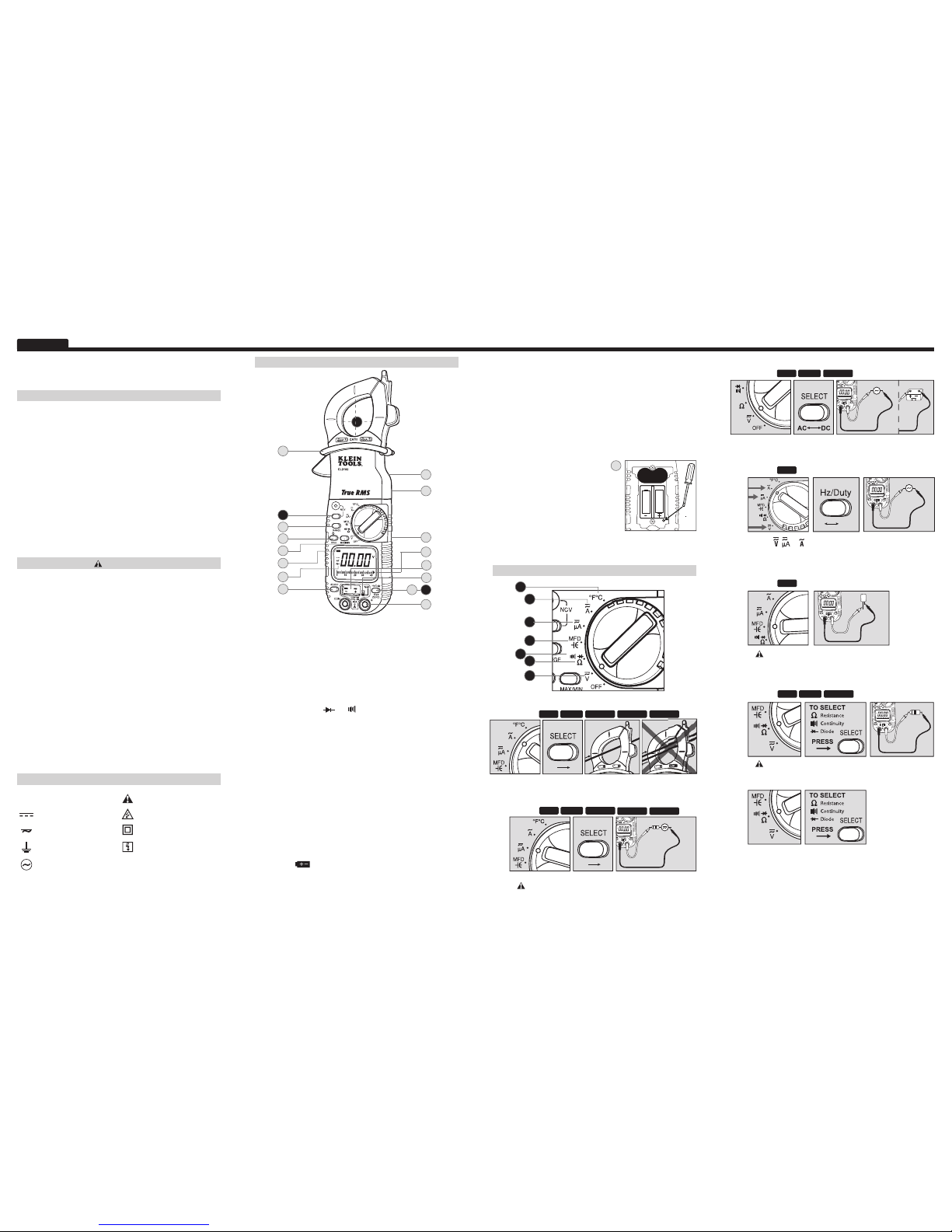
FEATURE DETAILS
CL2100
Instruction Manual
GENERAL SPECIFICATIONS
The Klein Tools CL2100 is a True RMS, auto-ranging clamp meter. It
measures AC / DC voltage, AC / DC current, resistance, capacitance,
frequency, duty cycle, and temperature. It can also test non-contact
voltage, diodes, and continuity.
• Operating Altitude: 2000 meters
• Humidity: 80% max
• Operating Temperature: 0°C / 32°F to 45°C / 113°F
• Storage Temperature: 0°C / 32°F to 60°C / 140°F
• Accuracy Temperature: 18°C / 64°F to 28°C / 82°F
• Temperature Coef cient: 0.1*(specified accuracy) / °C
• Dimensions: 8.875" x 3.375" x 1.5"
• Weight: 10.7oz.
• Calibration: Accurate for one year
• CAT Rating: CAT III 600V
• Accuracy: ± (% of reading + # of least significant digits)
WARNINGS
To ensure safe operation and service of the tester, follow these instructions.
Failure to observe these warnings can result in severe injury or death.
• Before each use, verify meter operation by measuring
a known voltage or current.
• Never use the meter on a circuit with voltages that exceed the
category based rating of this meter.
• Do not use the meter during electrical storms, or in wet weather.
• Do not use the meter or test leads if they appear to be damaged.
• Ensure meter leads are fully seated, and keep fingers away from
the metal probe contacts when making measurements.
• Do not open the meter to replace batteries while the probes
are connected.
• Use caution when working with voltages above 60V DC,
or 25V AC RMS. Such voltages pose a shock hazard.
• To avoid false readings that can lead to electrical shock,
replace batteries if a low battery indicator appears.
• Unless measuring voltage or current, shut off and lock out
power before measuring resistance or capacitance.
• Always adhere to local and national safety codes. Use individual
protective equipment to prevent shock and arc blast injury where
hazardous live conductors are exposed.
SYMBOLS
~
AC Alternating Current Warning or Caution
DC Direct Current Dangerous levels
DC/AC Voltage or Current Double Insulated Class II
Ground
Safe for disconnect
from live conductors
AC Source
A. Use CAT III rated leads or higher.
Do not attempt to measure more than 1000V DC or 750V AC or 2000µA.
B. Keep hands below line when measuring high current levels.
C. Auto Power-Off (Apo)
• Device will power off after 30 minutes non-use.
• Turn the dial or press a button to wake.
• Disabled during Max / Min function.
• Holding Select button while turning on disables Auto Power-Off.
D. Select Functionality Button
• Switch between AC and DC.
• Switch between
and .
• Switch between ˚F and ˚C.
E. Hold / Backlight / Worklight
• Press to hold the current input on the display.
• Press again to return to live reading.
• Press for 2 seconds to enable / disable lights.
• Using lights drains the batter y significantly.
F. Auto / Manual Range
• Press repeatedly to cycle through manual ranges.
• Press for 2 seconds to return to auto ranging mode.
•
AT is displayed on LCD only during auto ranging mode.
G. Max / Min Hold
• Press to enter Max / Min mode; the largest and smallest values
will be saved while in this mode.
• Press repeatedly to alternate between the maximum and minimum readings.
• Press for 2 seconds to return to live reading and clear the stored
maximum and minimum values.
H. I. Battery Replacement
• When indicator is displayed on the LCD, batteries must be replaced.
• Remove the back screw and replace 2 x AAA batteries.
J. Magnetic Back
• Attach instrument to metal for hands-free use.
1. AC/DC Current (large): < 400A
Features:
2. AC / DC Current (small): < 2000µA
Features:
MAX/MINRANGEHOLD
K. Bar Graph
• The bar graph shows an approximate analog representation
of a measurement.
• The bar graph responds much faster than the digital display.
• The scale of the bar graph is zero to the maximum reading of
the selected range.
L. Temperature Input Jack
• Input jack for K-type thermocouple probe.
M. Temperature Switch
• Move the switch down to measure temperature, and up to
measure all other functions that require standard test leads. Test
leads must be removed before using the temperature function.
N. Temperature Adjustment
• Remove batter y cover.
• Place temperature probe in distilled
water with stirred crushed ice
(a standard for 0°C and 32°F).
• Use a fine tip screwdriver to adjust
the screw recessed in the bottom
right corner of the battery cavity as
shown until the display reads 32°F.
O. Relative Reading / Zero mode
• Press for 2 seconds to enable/disable mode and store reading.
• Display will show the difference between the stored reading and
the live measurement.
FUNCTION INSTRUCTIONS
• Select AC or DC current source.
• Current above 2000µA will damage instrument.
Diode / Continuity Features: Continued on Reverse
• Select AC or DC voltage source.
4. Frequency (Hz) / Duty Cycle (See Feature Details)
Features:
HOLD
• Select , ,or setting.
• Frequencies greater than 500 kHz will display “0.000Hz”.
5. Capacitance: < 4000µF
Features:
HOLD
•
Safely discharge capacitor before measurement.
• Reading may take up to 60 seconds for large capacitors.
6. Resistance: < 40M
Ω
Features:
MAX/MINRANGEHOLD
• Do not measure resistance on a live circuit.
MAX/MINRANGEHOLD
• Center wire in guides for best accuracy.
• Opposing currents cancel (use line-splitter when necessar y).
7. Diode / Continuity
3. AC / DC Voltage: < 750V AC or 1000V DC
Features:
MAX/MIN
RANGE
HOLD
N
ZERO (DC)
ZERO (DC)
REL (AC)
REL (AC)
Page 3

CUSTOMER SERVICE
KLEIN TOOLS, INC.
450 Bond Street
Lincolnshire, IL 60069
1-877-775-5346
www.kleintools.com
139664
ENGLISH
www.kleintools.com
Manual de
Instrucciones
For Professionals...Since 1857
®
CL2100
ESPAÑOL
• VALOR EFICAZ (RMS)
VERDADERO
• RETENCIÓN
DE DATOS
• LUZ DE FONDO
• PROBADOR DE
TENSIÓN SIN
CONTACTOS
• GRÁFICO DE BARRAS
• MAX / MIN
• LUZ DE TRABAJO
• INTERVALO
AUTO / MANUAL
• PANTALLA DE
LCD DE 3999
CONTEOS CON
DÍGITOS DE 3-3/4
• TEMPERATURA
ESPAÑOL
SÍMBOLOS UTILIZADOS EN LA PANTALLA DE LCD
~
Medición de CA Medición de CC
-
Valor de CC negativo
Apo
Autoapagado activo
O
.L.
Sobrecarga:
Intervalo excedido
AT
Determinación
automática del intervalo
activa
Pila baja
HOLD
Retención en activo
MIN
Lectura mínima
M
AX
Lectura máxima
%
Modo de ciclo de servicio
Modo de frecuencia
V
Medición de tensión
A
Corriente en A
Ω
Resistencia en ohmios Prueba de diodo
F
Capacitancia en faradios Prueba de continuidad
Modo Relativo / Cero
n
Nano 10
-9
m
Mili 10
-3
µ
Micro 10
-6
M
Mega 10
6
k
Kilo 10
3
°F
Grados Fahrenheit
°C
Grados Celsios
GARANTÍA
Consulte www.kleintools.com <http://www.kleintools.com> , contacte a Klein
Tools llamando al 1-877-775-5346 ó visite a un distribuidor para obtener
información sobre la garantía.
LIMPIEZA
Apague el instrumento y desconecte los conductores de prueba. Limpie el
instrumento utilizando un paño húmedo. No utilice limpiadores abrasivos ni
solventes.
ALMACENAMIENTO
Retire las pilas cuando el instrumento no se vaya a usar durante un período de
tiempo prolongado. No lo exponga a altas temperaturas o humedad. Después de
un período de almacenamiento en condiciones extremas que excedan los límites
mencionados en la sección Especificaciones, deje que el instrumento regrese a
las condiciones de funcionamiento normales antes de utilizarlo.
ELIMINACIÓN / RECICLAJE
Precaución: Este símbolo indica que el equipo y sus accesorios
estarán sujetos a recogida y desecho correcto por separado.
8. Tensión sin contactos (NCV): > 25 V CA
ESPECIFICACIONES ELÉCTRICAS
Medición de tensión de CC
Intervalo Resolución Precisión
400mV ˜ 400V 0.1mV ˜ 0.1V ± (0.5% + 4 dígitos)
1000V 1V ± (0.8% + 10 dígitos)
Protección contra sobrecargas: 1000V
Medición de tensión de CA
Intervalo Resolución Precisión
400mV ˜ 750V 0.1mV ˜ 1V ± (2.0% + 5 dígitos)
Protección contra sobrecargas: 750V (RMS)
Respuesta de frecuencia: 40 a 400Hz
Tensión mínima para la medición de frecuencia: 200mV
Respuesta: Valor Eficaz (RMS) Verdadero
Medición de corriente CC
Intervalo Resolución Precisión
400µA 0.1µA
± (1.2% + 3 dígitos)
2000µA 1µA
40A 0.01A ± (2.5% + 15 dígitos)
400A 0.1A ± (1.5% + 8 dígitos)
Protección contra sobre cargas:
• Tensión: 600V (RMS)
• Corriente: 2000µA
Medición de corriente CA
Intervalo Resolución Precisión
400µA 0.1µA ± (2.0% + 5 dígitos)
2000µA 1µA ± (1.5% + 5 dígitos)
40A 0.01A ± (2.9 % + 15 dígitos)
400A 0.1A ± (1.9% + 8 dígitos)
Protección contra sobre cargas:
• Tensión: 600V (RMS)
• Corriente: 2000µA
Frequency: 45 a 400Hz
Corriente mínima para la medición de frecuencia: 400µA o 20A
Respuesta: Valor Eficaz (RMS) Verdadero
Medición de resistencia
Intervalo Resolución Precisión
400
Ω
˜
4MΩ 0.1Ω ˜ 0.001MΩ
± (1.0% + 4 dígitos)
40M
Ω 0.01MΩ
± (2.0% + 4 dígitos)
Protección contra sobrecargas: 600V (RMS)
Medición de capacitancia
Intervalo Resolución Precisión
40nF ˜ 4000µF 0.01nF ˜ 1µF ± (3.5% + 6 dígitos)
Protección contra sobrecargas: 600V (RMS)
Medición de frecuencia
Intervalo Resolución Precisión
99.99Hz ˜ 499.9kHz 0.01Hz ˜ 0.1kHz ± (0.1% + 4 dígitos)
Protección contra sobrecargas: 600V (RMS) Sensbilidad: 1.8V (RMS)
Medición del ciclo de servicio
Intervalo Resolución Precisión
0.1 ˜ 99.9% 0.1% ± (0.2% por kHz + 0.1% + 5 dígitos)
Protección contra sobrecargas: 600V (RMS)
Prueba de diodo
Protección contra
sobrecargas
Intervalo
Corriente
de prueba
Tensión de
circuito abierto
600V (RMS)
2.0V Appox. 0.25mA < 1.6V CC
Prueba de continuidad
Protección contra sobrecargas Tensión de circuito abierto
600V (RMS) < 0.44V
Medición de temperatura
Intervalo Resolución Precisión
-22°~14°F (-30°~-10°C) 0.1°F (0.1°C) ±5.4°F (±3.0°C)
15°~752°F (-9°~400°C) 0.1°F (0.1°C) ±(1.0% + [3.6°F or 2.0°C])
Overload Protection: 30V RMS
Detector de tensión sin contactos
Tensión de encendido
Appox. 25V CC
9. Temperatura
Características:
HOLD MAX/MIN REL
• NO aplique voltaje al termopar.
• Intervalo Fahrenheit: -22 a 752 ºF
• Intervalo centígrado:-30 a 400 ºC
V
AT
0 10 20 4030
Apo
V
AT
0 10 20 4030
Apo
HOLD MAX/MIN
HOLD MAX/MIN
La pantalla muestra:
• Caída de tensión en sentido directo
si la polarización es directa.
• “O.L.” si la polarización es inversa.
Características de diodo:
• La pantalla muestra resistencia.
• El zumbador suena si es menos de 30Ω.
Características de continuidad:
PRESS
and
HOLD
600V
400V
CATIII
CL1000
PRESS
and
HOLD
PRESIONE
Page 4

ESPAÑOL
V
AT
0 10 20 4030
Apo
V
AT
0 10 20 4030
Apo
V
AT
0 10 20 4030
Apro
V
AT
0 10 20 4030
Apo
V
AT
0 10 20 4030
Apo
7
1
5
2
3
6
9
PRESS
PRESS
PRESS
PRESS
Duty
Cycle
Hz
PARA SELECCIONAR
Resistencia
Continuidad
Diodo
PRESIONE
PARA SELECCIONAR
Resistencia
Continuidad
Diodo
PRESIONE
600V
400V
CATIII
600V
400V
CATIII
1
B
A
I
N
J
4
K
F
8
E
H
D
G
C
L
M
O
DETALLES DE LAS FUNCIONES
CL2100
Manual de Instrucciones
ESPECIFICACIONES GENERALES
El CL2000 de Klein Tools es un multímetro de pinza con determinación
automática del intervalo con valor eficaz (RMS) verdadero. Mide tensión
de CA / CC, corriente CA / CC, resistencia, capacitancia, frecuencia y ciclo
de servicio. También puede probar tensión, diodos y continuidad sin
contactos.
• Altitud de funcionamiento: 2000 metros
• Humedad: 80% máx
• Temperatura de funcionamiento: 0°C / 32°F a 45°C / 113°F
• Temperatura de almacenamiento: 0°C / 32°F a 60°C / 140°F
• Temperatura de precisión: 18°C / 64°F a 28°C / 82°F
• Coe ciente de temperatura: 0,1*(precisión especificada) / °C
• Dimensiones: 8,875 x 3,375 x 1,5 pulgadas
• Peso: 10,7 onzas
• Calibración: Precisa durante un año
• Cali cación CAT: CAT III 600V
• Precisión: ± (% de la lectura + No. de dígitos menos significativos)
ADVERTENCIAS
Para asegurar un funcionamiento y servicio seguros del probador, siga
estas instrucciones. Si no se hace caso de estas advertencias, el resultado
puede ser lesiones graves o muerte.
• Antes de cada uso, verifique el funcionamiento del multímetro midiendo
una tensión o una corriente conocida.
• No utilice nunca el multímetro en un circuito con tensiones que excedan
la capacidad nominal basada en la categoría de este multímetro.
• No utilice el multímetro durante tormentas eléctricas ni en tiempo mojado.
• No utilice el multímetro ni los conductores de prueba si parecen estar
dañados.
• Asegúrese de que los conductores de prueba del multímetro estén
completamente asentados y mantenga los dedos alejados de los contactos
metálicos de los conductores de prueba cuando haga mediciones.
• No abra el multímetro para reemplazar las pilas mientras los conductores
de prueba estén conectados.
• Tenga precaución cuando trabaje con tensiones superiores a 60 V CC, o 25 V
CA de valor eficaz (RMS). Dichas tensiones presentan un peligro de descarga.
• Para evitar lecturas falsas que pueden llevar a descargas eléctricas, reemplace
las pilas si aparece un indicador de pila baja.
• A menos que mida tensión o corriente, apague y bloquee el suministro
eléctrico antes de medir resistencia o capacitancia
• Cumpla siempre con los códigos de seguridad locales y nacionales.
Utilice equipo de protección individual para evitar las descargas eléctricas
y las lesiones por intensas corrientes de arco donde los conductores con
corriente peligrosos estén al descubierto.
SÍMBOLOS
~
CA Corriente alterna Advertencia o precaución
CC Corriente continua Niveles peligrosos
Tensión o corriente CC/CA Conexión a tierra
Con aislamiento
doble de Clase II
Seguro para desconectar
de conductores con
corriente
Fuente de CA
A. Utilice conductores de prueba con capacidad nominal CAT III o mayor.
No intente medir más de 1000 V CC ó 750 V CA ó 2000 μA.
B. Mantenga las manos por debajo de la línea cuando mida niveles
altos de corriente.
C. Autoapagado (Apo)
• El dispositivo se apagará después de 30 sin utilizarlo.
• Gire el dial o presione un botón para activarlo.
• Desactivado durante la función Max / Min.
• Si se mantiene presionado el botón Select mientras se enciende
la unidad, se desactiva el autoapagado.
D. Botón de funcionalidad Select
• Cambie entre CA y CC.
• Cambie entre y .
E. Retener / Luz de fondo / Luz de trabajo
• Presione para retener la entrada de corriente en la pantalla.
• Presione de nuevo para regresar a la lectura en vivo.
• Presione durante 2 segundos para activar / desactivar las luces.
• La utilización de las luces drena significativamente la pila.
F. Intervalo Auto / Manual
• Presione repetidamente para recorrer en ciclo los intervalos manuales.
• Presione durante 2 segundos para regresar al modo de determinación
automática del intervalo.
• AT se muestra en la pantalla de LCD solamente durante el modo de
determinación automática del intervalo.
G. Retención de Max / Min
• Presione para ingresar al modo Max / Min; los valores más grande y más
pequeño se almacenarán mientras se esté en este modo.
• Presione repetidamente para alternar entre las lecturas máxima y mínima.
• Presione durante 2 segundos para regresar a la lectura en vivo y eliminar
los valores máximo y mínimo almacenados.
H. I. Reemplazo de las pilas
• Cuando el indicador se muestre en la pantalla de LCD,
las pilas deben ser reemplazadas.
• Retire el tornillo trasero y reemplace las pilas con 2 pilas AAA.
J. Parte trasera magnética
• Sujete el instrumento a metal para permitir su uso con las manos libres.
1. Corriente CA / CC (grande): < 400 A
Características:
2. Corriente CA / CC (pequeña): < 2000 μA
Características:
MAX/MINRANGEHOLD
K. Grá co de barras
• El gráfico de barras muestra una representación analógica
aproximada de una medición.
• El gráfico de barras responde mucho más rápidamente que
la pantalla digital.
• La escala del gráfico de barras comprende desde cero hasta
la lectura máxima del intervalo seleccionado.
L. Conector hembra de entrada de temperatura
• Conector hembra de entrada para sonda de termopar tipo K.
M. Interruptor de temperatura
• Mueva el interruptor hacia abajo para medir la temperatura y muévalo
hacia arriba para medir todas las demás funciones que requieren
conductores de prueba estándar.
N. Ajuste de temperatura
• Retire la cubierta del compartimiento
de las pilas
• Coloque la sonda de temperatura en
agua destilada con hielo picado
removido (un estándar para 0 ºC y 32 ºF).
• Utilice un destornillador de punta fina para
• ajustar el tornillo embutido en la esquina inferior derecha de la cavidad
de las pilas, de la manera que se muestra en la ilustración, hasta que la
lectura de la pantalla sea 32º F.
O. Modo de lectura relativa / cero
• Presione durante 2 segundos para activar /
desactivar el modo y almacenar la lectura.
• La pantalla mostrará la diferencia entre la lectura almacenada
y la medición en vivo.
INSTRUCCIONES DE LAS FUNCIONES
• Seleccione la fuente de corriente CA o CC.
• Una corriente superior a 2000 μA dañará el instrumento.
Funciones de Diodo/ Continuidad: Continúa al dorso
• Seleccione la fuente de tensión de CA o CC.
4. Frecuencia (Hz) / Ciclo de servicio (consulte “Detalles de las funciones”)
Características:
HOLD
• Seleccione el ajuste , , o .
• Las frecuencias superiores a 500 kHz mostrarán “0.000Hz”.
5. Capacitancia: < 4000 μF
Características:
HOLD
• Descargue el capacitor de manera segura antes de realizar la medición.
• La lectura puede tomar hasta 60 segundos en el caso de
capacitores grandes.
6. Resistencia: < 40 MΩ
Características:
MAX/MINRANGEHOLD
• No mida resistencia en un circuito que tenga corriente.
MAX/MINRANGEHOLD
• Centre el cable en las guías para lograr la mejor precisión.
• Las corrientes opuestas se cancelan
(utilice el separador de líneas cuando sea necesario).
7. Diodo / Continuidad
3. Tensión de CA / CC: < 750 V CA ó 1000 V CC
Características:
REL
MAX/MIN
RANGE
HOLD
N
ZERO (DC)
ZERO (DC)
REL (AC)
REL (AC)
Page 5

CUSTOMER SERVICE
KLEIN TOOLS, INC.
450 Bond Street
Lincolnshire, IL 60069
1-877-775-5346
www.kleintools.com
139665
ENGLISH
www.kleintools.com
Mode
d'Emploi
FRANÇAIS
For Professionals...Since 1857
®
CL2100
• VALEUR
EFFICACE VRAIE
• GRAPHIQUE
À BARRES
• RÉTENTION
MAX / MIN
• RELATIVE / ZÉRO
• RÉTROÉCLAIRAGE
• LAMPE DE TRAVAIL
• LCD 3 999 POINTS
3 3/4 CHIFFRES
• PLAGE
AUTO / MANUEL
• TESTEUR DE
TENSION
SANS CONTACT
• TEMPÉRATURE
SYMBOLES UTILISÉS SUR L'ÉCRAN ACL
~
Mesure c.a. Mesure c.c.
-
Valeur c.c. négative
AT
Plage automatique
activée
O
.L.
Surcharge :
Limite de plage dépassée
Apo
Fonction de Mise hors
tension automatiquement
active
Décharge partielle
des piles
HOLD
Maintien en position
activée
MIN
Lecture minimum
M
AX
Lecture maximum
%
Mode de cycle de service
Mode de lecture relative
/ Mode Zéro
V
Mesure de la tension
A
Courant en ampères
Ω
Résistance en Ohms Test de diode
F
Capacité en Farads Test de continuité
Mode de fréquence
n
Nano 10
-9
m
Milli 10
-3
µ
Micro 10
-6
M
Méga 10
6
k
Kilo 10
3
°F
Degrés Fahrenheits
°C
Degrés Celsius
PRESS
and
HOLD
600V
400V
CATIII
CL1000
PRESS
and
HOLD
GARANTIE
Voir www.kleintools.com <http://www.kleintools.com> , contacter Klein Tools
au 1-877-775-5346, ou aller chez un distributeur pour obtenir des informations
sur la garantie.
NETTOYAGE
Éteignez l'instrument et déconnectez les fils de test. Nettoyez l'instrument en
utilisant un tissu humide. N’utilisez pas de solvants ou de produits de nettoyage
abrasifs.
RANGEMENT
Retirez les piles lorsque l'instrument ne va pas être utilisé pendant une période
prolongée. N'exposez pas à une température ou une humidité élevée. À la suite
d'une période de rangement dans des conditions extrêmes dépassant les limites
mentionnées dans la section consacrée aux spécifications, laissez l'instrument
retourner dans des conditions de mesure normales avant de vous en servir à
nouveau.
MISE AU REBUT/RECYCLAGE
Mise en garde: Ce symbole indique que l'équipement et ses
accessoires doivent faire l'objet d'une élimination distincte et d'une
mise au rebut conforme aux règlements.
8. Tension sans contact : > 25 V C.A.
SPÉCIFICATIONS ÉLECTRIQUES
Mesure de la tension c.c.
Plage Résolution Précision
400mV ˜ 400V 0.1mV ˜ 0.1V ± (0.5% + 4 chiffres)
1 000V 1V ± (0.8% + 10 chiffres)
Protection contre les surcharges : 1000V
Mesure de la tension c.a.
Plage Résolution Précision
400mV ˜ 750V 0.1mV ˜ 1V ± (2.0% + 5 chiffres)
Protection contre les surcharges : 750V RMS
Réponse en fréquence : 40 à 400Hz
Tension minimum pour la mesure de la fréquence : 200mV
Réponse : Valeur Efficace Vraie
Mesure du courant c.c.
Plage Résolution Précision
400µA 0.1µA
± (1.2% + 3 chiffres)
2 000µA 1µA
40A 0.01A ± (2.5% + 15 chiffres)
400A 0.1A ± (1.5% + 8 chiffres)
Protection contre les surcharges :
• Tension : 600V eff.
• Courant : 2000µA
Mesure du courant c.a.
Plage Résolution Précision
400µA 0.1µA ± (2.0% + 5 chiffres)
2 000µA 1µA ± (1.5% + 5 chiffres)
40A 0.01A ± (2.9 % + 15 chiffres)
400A 0.1A ± (1.9% + 8 chiffres)
Protection contre les surcharges :
• Tension : 600V eff.
• Courant : 2000µA
Fréquence : 45 à 400Hz
Tension minimum pour la mesure de la fréquence : 400µA ou 20A
Réponse : Valeur Efficace Vraie
Mesure de la résistance
Plage Résolution Précision
400
Ω
˜
4MΩ 0.1Ω ˜ 0.001MΩ
± (1.0% + 4 chiffres)
40M
Ω 0.01MΩ
± (2.0% + 4 chiffres)
Protection contre les surcharges : 600V eff.
Mesure de la capacité
Plage Résolution Précision
40nF ˜ 4 000µF 0.01nF ˜ 1µF ± (3.5% + 6 chiffres)
Protection contre les surcharges : 600V eff.
Mesure de la fréquence
Plage Résolution Précision
99.99Hz ˜ 499.9kHz 0.01Hz ˜ 0.1kHz ± (0.1% + 4 chiffres)
Protection contre les surcharges : 600V eff. Sensibilité : 1.8V eff.
Mesure du cycle de service
Plage Résolution Précision
0.1 ˜ 99.9% 0.1% ± (0.2% par kHz + 0.1% + 5 chiffres)
Protection contre les surcharges : 600V eff.
Test de diode
Protection contre
les surcharges
Plage Test du courant
Tension de
circuit ouvert
600V eff.
2.0V Appx. 0.25mA < 1.6V CC
Test de continuité
Protection contre les surcharges Tension de circuit ouvert
600V eff. < 0.44V
Mesure de la température
Plage Résolution Précision
-22°~14°F (-30°~-10°C) 0.1°F (0.1°C) ±5.4°F (±3.0°C)
15°~752°F (-9°~400°C) 0.1°F (0.1°C) ±(1.0% + [3.6°F or 2.0°C])
Protection contre les surcharges : 30V eff.
Détecteur de tension sans contact
Tension act.
Appx. 25V CA
9. Température
Caractéristiques:
HOLD MAX/MIN REL
• N’appliquez PAS de tension au thermocouple.
• Plage de température en degrés Fahrenheits : -22º à 752º
• Plage de température en degrés Celsius :-30º à 400º
V
AT
0 10 20 4030
Apo
V
AT
0 10 20 4030
Apo
HOLD
MAX/MIN
HOLD MAX/MIN
FRANÇAIS
L’écran affiche :
• Chute de tension directe en cas de
polarisation en sens direct.
• « O.L. » en cas de polarisation dans le sens
inverse.
Caractéristiques de la diode :
• L’écran affiche la résistance.
• L’avertisseur sonore retentit si la valeur est
inférieure à 30 Ω.
Caractéristiques de continuité :
APPUYEZ
Page 6

FRANÇAIS
V
AT
0 10 20 4030
Apo
V
AT
0 10 20 4030
Apo
V
AT
0 10 20 4030
Apro
V
AT
0 10 20 4030
Apo
V
AT
0 10 20 4030
Apo
7
1
5
2
3
6
9
PRESS
PRESS
PRESS
PRESS
Duty
Cycle
Hz
600V
400V
CATIII
600V
400V
CATIII
1
B
A
I
N
J
4
K
F
8
E
H
D
G
C
L
M
O
DÉTAILS DES FONCTIONS
CL2100
Mode d’Emploi
SPÉCIFICATIONS GÉNÉRALES
L’appareil Klein Tools CL2000 est une pince ampèremétrique à VQM
vraie et à sélection automatique de plage. Il mesure la tension c.a. / c.c.,
le courant électrique c.a. / c.c., la résistance, la capacité, la fréquence et
le cycle de service. Il peut également tester la tension sans contact, les
diodes et la continuité des circuits.
• Altitude de service : 2 000 mètres
• Humidité : 80 % max
• Température de service : 0°C / 32°F à 45°C / 113°F
• Température de stockage : 0°C / 32°F à 60°C / 140°F
• Précision en température : 18°C / 64°F à 28°C / 82°F
• Coef cient de température : 0,1* (précision spécifiée) / °C
• Dimensions : 8,875 po x 3,375 po x 1,5 po
• Poids : 10,7 oz
• Étalonnage : Précis pendant un an
• Quali cation de cat. : CAT III 600V
• Précision :
± (% de lecture + nombre de chiffres les moins significatifs)
AVERTISSEMENTS
Pour assurer un fonctionnement et un service sans danger du testeur,
suivez les instructions ci-après. Le non-respect des ces avertissements
risquerait de causer des blessures graves ou même la mort :
• Avant chaque emploi, vérifiez le fonctionnement de l’appareil de mesure en
mesurant une tension ou un courant connu.
• N’utilisez jamais cet appareil de mesure sur un circuit dont la tension dépasse la
qualification de catégorie de cet appareil de mesure.
• N’utilisez pas cet appareil de mesure pendant un orage électrique ou par temps
humide.
• N’utilisez pas l’appareil de mesure ou les fils d’essai s’ils semblent être
endommagés.
• Assurez-vous que les fils de connexion de l’appareil de mesure sont bien à leur
place, et gardez les doigts à distance des contacts de la sonde en métal lorsque
vous effectuez des mesures.
• N’ouvrez pas l’appareil de mesure pour remplacer des piles pendant que les
sondes sont toujours connectées.
• Prenez des précautions lorsque vous travaillez avec des tensions de plus de 60 V
c.c. ou 25 V c.a. eff. De telles tensions présentent un risque de choc électrique.
• Pour éviter des lectures erronées qui pourraient causer un choc électrique,
remplacez les piles si un voyant de décharge partielle des piles s’allume.
• Sauf si vous êtes en train de mesurer une tension ou un courant, mettez l’appareil
hors circuit et verrouillez-le avant de mesurer une résistance ou une capacité.
• Respectez toujours les dispositions des codes de sécurité national et local.
Utilisez des équipements de protection individuelle pour éviter tout risque de
choc électrique ou de blessure causée par une explosion électrique lorsque des
conducteurs sous tension dangereux sont exposés.
SYMBOLES
~
Courant alternatif c.a.
Avertissement ou Mise
en garde
Courant continu c.c. Tension ou courant c.c./c.a
Niveaux dangereux Classe II, double isolation
Masse
Sans danger pour
la déconnexion de
conducteurs sous tension
Source c.a.
A. Utilisez des conducteurs de cat. III ou plus.
Ne tentez pas de mesurer plus de 1 000 V c.c. ou de 750 V c.a., ou 2 000 µA.
B. Maintenez les mains au-dessous de la ligne lorsque vous mesurez des
niveaux de courant élevés.
C. Mise hors tension automatiquement (Apo)
• L’appareil se mettra hors tension au bout de 30 minutes d’inutilisation.
• Tournez le cadran ou appuyez sur un bouton pour réactiver l’appareil.
• Désactivé pendant la fonction Max / Min.
• Le maintien du bouton Select en position enfoncée pendant la mise
en service de l’appareil désactive la fonction de mise hors tension
automatiquement (Apo).
D. Bouton de sélection de fonctionnalité
• Commutation entre c.a. et c.c.
• Commutation entre
et .
E. Rétention / Rétroéclairage / Lampe de travail
• Appuyez pour maintenir l’arrivée de courant sur l’écran.
• Appuyez à nouveau pour retourner à la valeur actuelle.
• Appuyez et maintenez enfoncé pendant deux secondes pour activer /
désactiver les lumières.
• L’utilisation des lumières décharge rapidement les piles.
F. Plage auto / manuelle
• Appuyez de façon répétée pour parcourir les plages manuelles.
• Appuyez et maintenez enfoncé pendant deux secondes pour retourner
dans le mode de sélection automatique de plage.
• AT est affiché sur l’écran ACL seulement dans le mode de sélection
automatique de plage.
G. Rétention Max / Min
• Appuyez pour entrer dans le mode Max / Min ; les valeurs les plus
grandes et les plus petites seront enregistrées pendant que vous serez
dans ce mode.
• Appuyez de façon répétée pour alterner entre la lecture de la valeur maximum
et la lecture de la valeur minimum.
• Appuyez et maintenez enfoncé pendant deux secondes pour retourner
à la valeur actuelle et effacer les valeurs max. et min. enregistrées alors.
H. I. Remplacement des piles
• Lorsque le voyant est affiché sur l’écran ACL, cela signifie
qu’il faut changer les piles.
• Retirez la vis arrière, et remplacez les 2 piles AAA.
J. Dossier magnétique
• Attachez l’instrument à une surface en métal afin d’avoir les mains libres.
1. Courant c.a. / c.c. (fort) : < 400A
Caractéristiques :
2. Courant c.a. / c.c. (faible) : < 2 000µA
Caractéristiques:
MAX/MINRANGEHOLD
K. Graphique à barres
• Le graphique à barres montre une représentation analogique
approximative d’une mesure.
• Le graphique à barres répond beaucoup plus rapidement
que l’affichage numérique.
• L’échelle du graphique à barres va de zéro à la lecture maximum
dans la plage sélectionnée.
L. Prise d’entrée pour la mesure de la température
• Prise d’entrée pour une sonde à thermocouple de type K
M. Thermocontact
• Déplacez le thermocontact vers le bas pour mesurer la température,
ou vers le haut pour mesurer toutes les autres fonctions qui
nécessitent des fils de test standard.
• Les fils de tests doivent être retirés
avant d’utiliser la fonction de température.
N. Réglage de la température
• Retirez le cache du compartiment des piles.
• Placez la sonde de température dans de
l’eau distillée avec de la glace écrasée
remuée (la norme pour 0° C et 32° F).
• Utilisez un tournevis à pointe fine pour
ajuster la vis encastrée dans le coin inférieur droit de la cavité des piles
comme illustré jusqu’à ce que l’on puisse lire 32° F sur l’écran.
O. Mode de lecture relative / Mode Zéro
• Appuyez et maintenez enfoncé pendant deux secondes pour activer/
désactiver le mode et la lecture des données enregistrées.
• L’écran affichera alors la différence entre les valeurs enregistrées
et les mesures actuelles.
INSTRUCTIONS RELATIVES AUX FONCTIONS
• Sélectionnez la source de courant c.a. ou c.c.
• Un courant supérieur à 2 000 µA endommagera l’instrument.
• Caractéristiques de continuité/diode : Suite au verso
• Sélectionnez la source de tension c.a. ou c.c.
4. Fréquence (Hz) / Cycle de service (voir la rubrique Détails des fonctions)
Caractéristiques :
HOLD
• Sélectionnez le paramètre , , ou .
• Les fréquences supérieures à 500 kHz causeront l’affichage
de la valeur « 0,000 Hz ».
5. Capacité : < 4 000µF
Caractéristiques :
HOLD
• Déchargez le condensateur pour raison de sécurité avant d’effectuer
la mesure.
• L’affichage de la lecture peut prendre jusqu’à 60 secondes dans le
cas des grands condensateurs.
6. Résistance : < 40 M
Ω
Caractéristiques :
MAX/MINRANGEHOLD
• Ne mesurez pas la résistance sur un circuit sous tension.
MAX/MINRANGEHOLD
• Centrage des fils dans les guides pour assurer la précision maximum.
• Les courants contraire s'annulent (utilisez des diviseurs de lignes si besoin est).
7. Diode / Continuité
3. Tension c.a./c.c. : < 750 V c.a. ou 1 000 V c.c.
Caractéristiques :
REL
MAX/MIN
RANGE
HOLD
N
ZERO (DC)
ZERO (DC)
REL (AC)
REL (AC)
PARA SÉLECTIONNER
Résistance
Continuité
Diode
APPUYEZ
PARA SÉLECTIONNER
Résistance
Continuité
Diode
APPUYEZ
 Loading...