

Page 1
INSTRUCTION MANUAL
ENGLISH
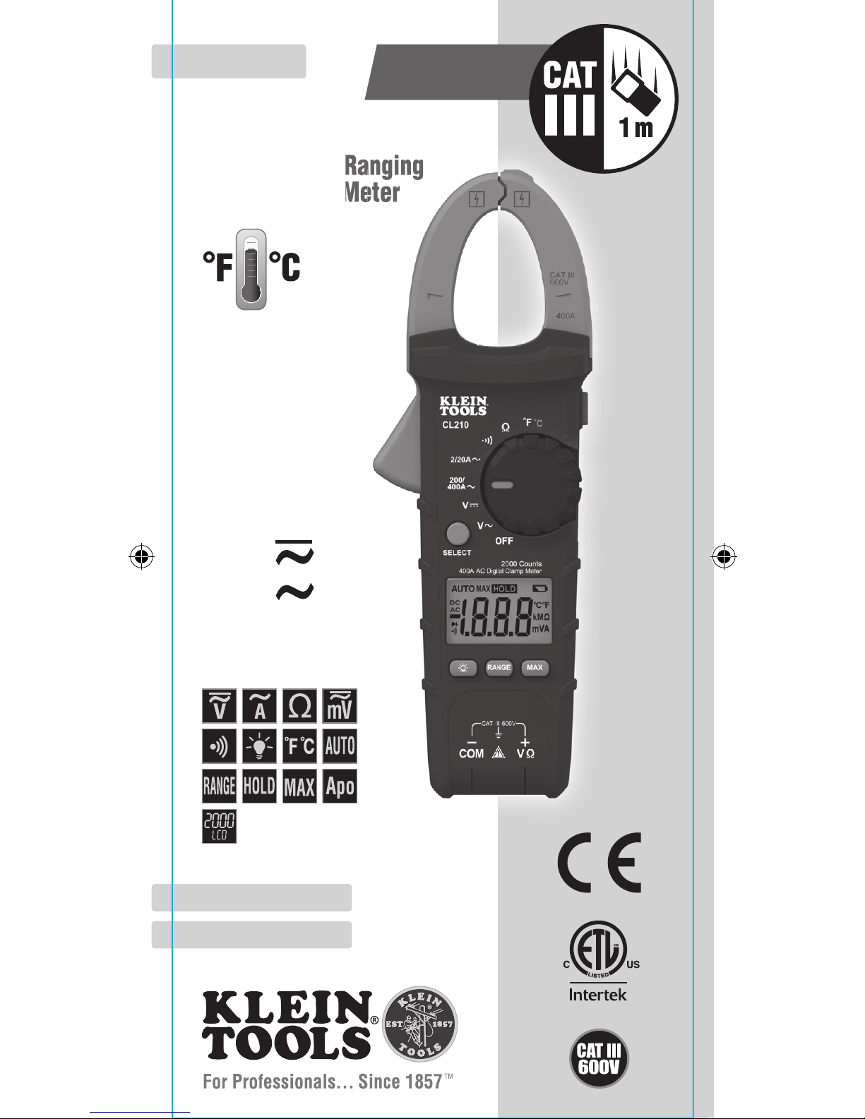
CL210
FRANÇAIS pg. 29
ESPAÑOL pg. 15
400A AC Auto-Ranging
Digital Clamp Meter
• AUTO-RANGING
• DATA HOLD
• RANGE HOLD
• TEMPERATURE
• AUDIBLE
CONTINUITY
Ω
Page 2
2
GENERAL SPECIFICATIONS
Klein Tools CL210 is an automatically ranging digital clamp-meter that
measures AC current via the clamp, AC/DC voltage, resistance and
continuity via test-leads, and temperature via a thermocouple probe.
• Operating Altitude: 6562 ft. (2000m)
• Relative Humidity: <95% non-condensing
• Operating Temp: 32° to 122°F (0° to 50°C)
• Storage Temp: 14° to 122°F (-10° to 50°C)
• Accuracy: Values stated at 65° to 83°F (18° to 28°C)
• Temp Coefcient: 0.1 x (Quoted Accuracy) per °C above
28°C or below 18°C, corrections are required when ambient
working temp is outside of Accuracy Temp range
• Dimensions: 8.66" x 3.03" x 1.61" (220 x 77 x 41 mm)
• Weight: 9.88 oz. (280 g) including batteries
• Calibration: Accurate for one year
• Standards: Conforms to: UL 61010-1, UL 61010-2-032,
UL 61010-2-033.
Certified to: CAN/CSA C22.2 NO. 61010-1,
61010-2-032, 61010-2-033, IEC EN 61010-1,
61010-2-032, 61010-2-033, IEC EN 61326-1
• Pollution degree: 2
• Accuracy: ± (% of reading + # of least significant digits)
• Drop Protection: 3.3 ft. (1m)
• Safety Rating: CATIII 600V, Class 2, Double insulation
• Electromagnetic Environment: IEC EN 61326-1. This
equipment meets requirements for use in basic and controlled
electromagnetic environments like residential properties,
business premises, and light-industrial locations.
Specifications subject to change.
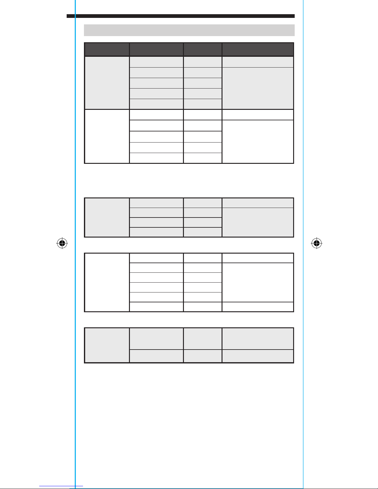
ELECTRICAL SPECIFICATIONS
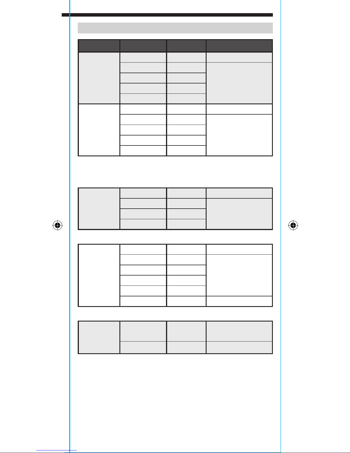
Function Range Resolution Accuracy
AC Voltage
(V AC)
200.0mV 0.1mV ±(2.5% + 10 digits)
2.000V 1mV
20.00V 10mV
200.0V 100mV
600V 1V
DC Voltage
(V DC)
200.0mV 0.1mV ±(1.0% + 8 digits)
2.000V 1mV
20.00V 10mV
200.0V 100mV
600V 1V
Input Impedance: 10MΩ
Frequency Range: 45 to 400Hz
Maximum Input: 600V AC RMS or 600V DC
AC Current
(A AC)
2.000A 1mA ±(2.5% + 30 digits)
20.00A 10mA
400A 1A
Frequency Range: 50 to 60Hz
Resistance
200.0Ω 0.1Ω ±(1.2% + 5 digits)
2.000KΩ 1Ω
20.00kΩ 10Ω
200.0kΩ 100Ω
2.000MΩ 1kΩ
20.00MΩ 10kΩ ±(2.0% + 5 digits)
Maximum Input: 600V AC RMS or 600V DC
Temperature
-40° to 1832°F
1°F
-40° to 1000°C
1
°C ±(2.8% + 6 digits)
ENGLISH
OTHER MEASUREMENT APPLICATIONS
Maximum Input: 600V AC RMS or 600V DC
• Continuity Check: Audible signal <10Ω, max current 1.5mA
• Sampling Frequency: 3 samples per second
• Auto Power off: After ~15 minutes of inactivity
• Overload: "OL" indicated on display
• Polarity: "-" on display indicates negative polarity
• Display: 3 ½ digit, 2000 Count LCD
Page 3
3
ELECTRICAL SPECIFICATIONS
Function Range Resolution Accuracy
AC Voltage
(V AC)
200.0mV 0.1mV ±(2.5% + 10 digits)
2.000V 1mV
±(2.0% + 5 digits)
20.00V 10mV
200.0V 100mV
600V 1V
DC Voltage
(V DC)
200.0mV 0.1mV ±(1.0% + 8 digits)
2.000V 1mV
±(1.0% + 3 digits)
20.00V 10mV
200.0V 100mV
600V 1V
Input Impedance: 10MΩ
Frequency Range: 45 to 400Hz
Maximum Input: 600V AC RMS or 600V DC
AC Current
(A AC)
2.000A 1mA ±(2.5% + 30 digits)
20.00A 10mA
±(2.0% + 10 digits)200.0A 100mA
400A 1A
Frequency Range: 50 to 60Hz
Resistance
200.0Ω 0.1Ω ±(1.2% + 5 digits)
2.000KΩ 1Ω
±(1.2% + 3 digits)
20.00kΩ 10Ω
200.0kΩ 100Ω
2.000MΩ 1kΩ
20.00MΩ 10kΩ ±(2.0% + 5 digits)
Maximum Input: 600V AC RMS or 600V DC
Temperature
-40° to 1832°F
1°F
≤0°F ±(2.8% + 12 digits)
>0°F ±(2.8% + 6 digits)
-40° to 1000°C
1
°C ±(2.8% + 6 digits)
OTHER MEASUREMENT APPLICATIONS
Maximum Input: 600V AC RMS or 600V DC
• Continuity Check: Audible signal <10Ω, max current 1.5mA
• Sampling Frequency: 3 samples per second
• Auto Power off: After ~15 minutes of inactivity
• Overload: "OL" indicated on display
• Polarity: "-" on display indicates negative polarity
• Display: 3 ½ digit, 2000 Count LCD
Page 4
4
WARNINGS
To ensure safe operation and service of the meter, follow these
instructions. Failure to observe these warnings can result in
severe injury or death.
• Before each use verify meter operation by measuring a known
voltage or current.
• Never use the meter on a circuit with voltages that exceed the
category based rating of this meter.
• Do not use the meter during electrical storms or in wet weather.
• Do not use the meter or test leads if they appear to be damaged.
• Use only with CAT III or CAT IV rated test leads.
• Ensure meter leads are fully seated, and keep fingers away
from the metal probe contacts when making measurements.
• Do not open the meter to replace batteries while the probes
are connected.
• Use caution when working with voltages above 25V AC RMS
or 60V DC. Such voltages pose a shock hazard.
• To avoid false readings that can lead to electrical shock,
replace batteries when a low battery indicator appears.
• Do not attempt to measure resistance or continuity on a live
circuit.
• Always adhere to local and national safety codes. Use personal
protective equipment to prevent shock and arc blast injury
where hazardous live conductors are exposed.
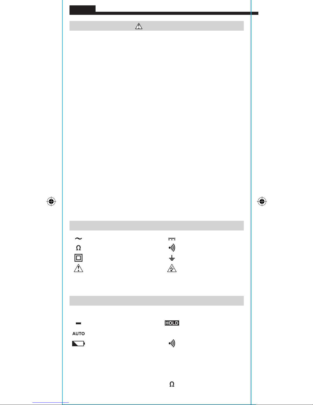
SYMBOLS ON METER
AC (Alternating Current) DC (Direct Current)
Resistance (in Ohms) Audible Continuity
Double Insulated Class II Ground
Warning or Caution
Risk of Electrical Shock
V Voltage (Volts) A Amperage (Amps)
°F/°
C
Temperature (Fahrenheit / Celsius)
SYMBOLS ON LCD
AC AC (Alternating Current) DC DC (Direct Current)
Negative Reading Data Hold
Auto Ranging MAX Maximum Value Hold
Low Battery Audible Continuity
°
F
Degrees (Fahrenheit)
°
C
Degrees (Celsius)
M
Mega (value x 106)
k
kilo (value x 103)
m
milli (value x 10-3)
V
Volts
A
Amps Ohms
ENGLISH
Page 5

5
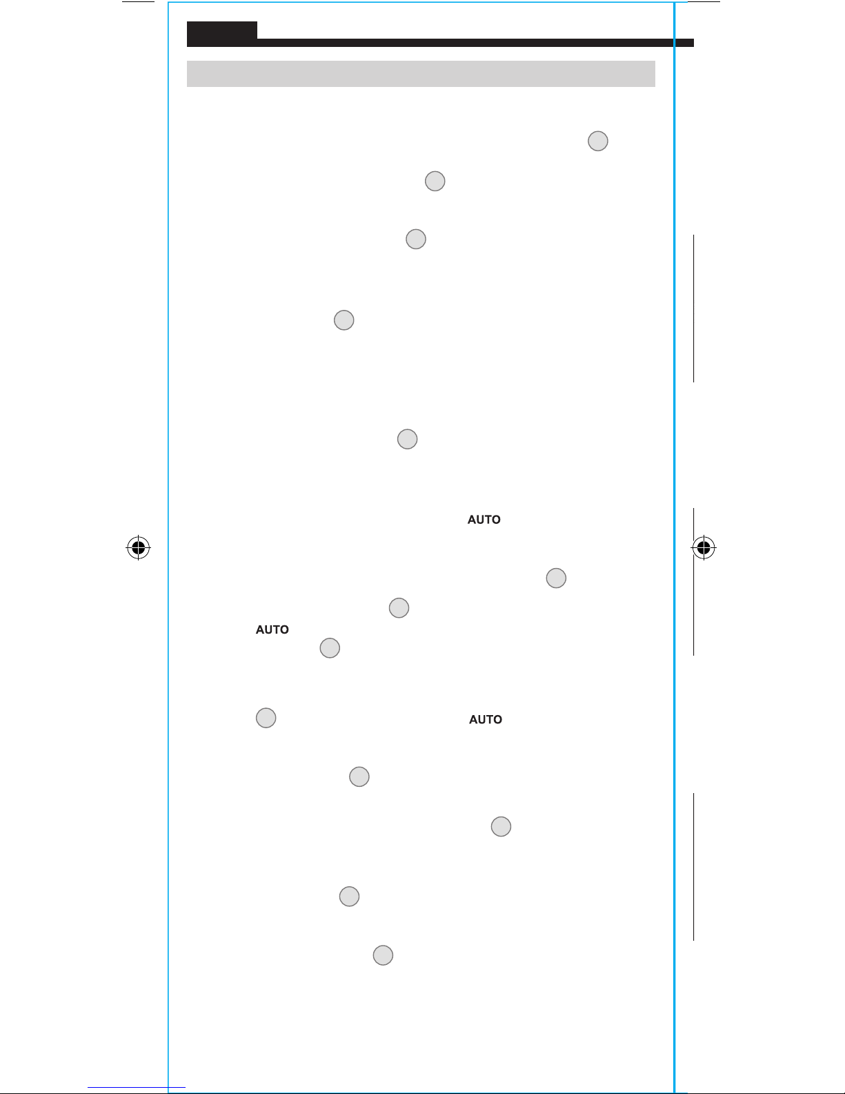
FEATURE DETAILS
1
6
2
3
10
12
5
8
7
4
1.
2000 count LCD display
7.
"RANGE" button
2.
Function selector switch8."MAX" (Maximum) button
3.
Clamp
9.
Data Hold button
4.
"COM" jack
10.
Clamp trigger (press to open clamp)
5.
"VΩ" jack
11.
Arrow markings
6.
Backlight button
12.
"SELECT" button
11
9
NOTE: There are no user-serviceable parts inside meter.
Page 6
6
FUNCTION BUTTONS
ON/OFF
To power ON the meter, rotate the Function Selector switch
2
from
the OFF setting to any measurement setting. To power OFF the meter,
rotate the Function Selector switch
2
to the OFF setting. By default,
the meter will automatically power OFF after 15 minutes of inactivity.
If the meter automatically powers OFF while in a measurement
setting, rotate Function Selector
2
switch to any other setting
(excluding the OFF setting) to power ON the meter.
"SELECT" BUTTON (FOR SECONDARY FUNCTIONS)
The "SELECT" button
12
activates the secondary function for the
temperature setting, switching between °F and °C. The default
setting (°F) is printed on the meter in white; the secondary setting
(°C) is printed on the meter in orange.
BACKLIGHT
Press Backlight button symbol
6
to turn ON or OFF the backlight.
The backlight does not automatically power OFF.
RANGE
The meter defaults to auto-ranging mode
. This mode
automatically determines the most appropriate measurement range
for the testing that is being conducted.
To manually force the meter to
measure in a different range, use the
"RANGE"
button
7.
1. Press the "RANGE" button
7
to manually select measurement
range (
is deactivated on the LCD). Repeatedly press the
"RANGE" button
7
to cycle through the available ranges,
stopping once the desired range is reached.
2. To return to auto-ranging mode, press and hold the "RANGE"
button
7
for more than one second ( is reactivated).
MAX
When the "MAX" button
8
is pressed, the meter keeps track of the
Maximum value as the meter continues to take samples.
1. When measuring, press "MAX" button
8
to display the
maximum value. If a new maximum occurs, the display
updates with that new value.
2. Press "MAX" button 8 again to return to normal measuring mode.
DATA HOLD
Press the Data Hold button
9
to hold the current measurement on
the display. Press again to return to live measuring mode.
ENGLISH
5/32"
(4 mm)
.7" (18 mm)
Page 7
7
OPERATING INSTRUCTIONS
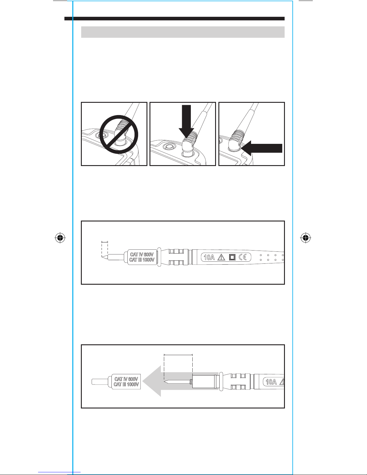
CONNECTING TEST LEADS
Do not test if leads are improperly seated. Results could cause
intermittent display readings. To ensure proper connection, firmly
press leads into the input jack completely. Lead guard should be
flush with the meter’s faceplate.
TESTING IN CAT III / CAT IV MEASUREMENT LOCATIONS
Ensure the test lead shield is pressed firmly in place. Failure to use
the CATIII / CATIV shield increases arc-flash risk.
TESTING IN CAT II MEASUREMENT LOCATIONS
CAT III / CAT IV shields may be removed for CAT II locations. This
will allow testing on recessed conductors such as standard wall
outlets. Take care not to lose the shields.
PRESS
NO GAP
5/32"
(4 mm)
.7" (18 mm)
Page 8

8
OPERATING INSTRUCTIONS
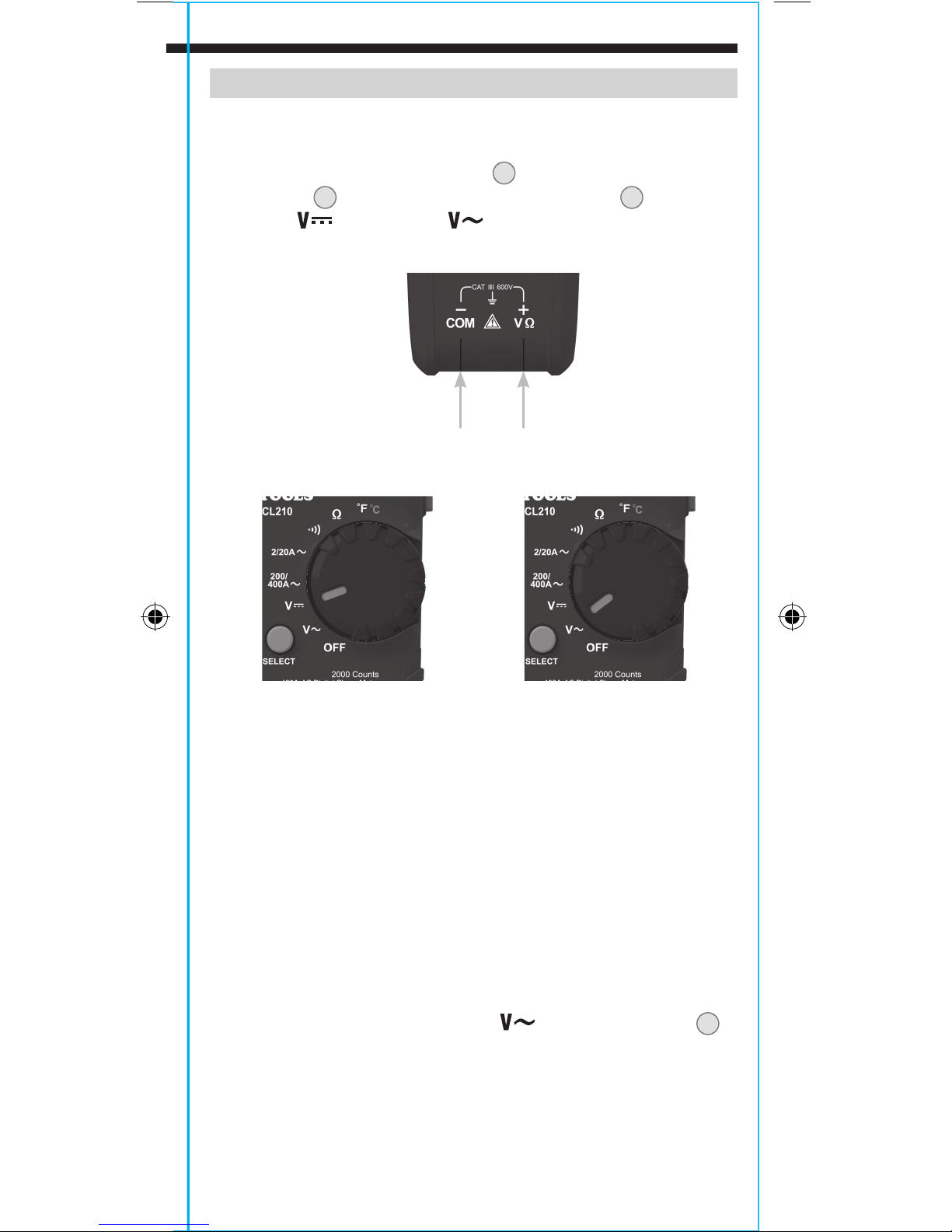
AC/DC VOLTAGE (LESS THAN 600V)
1. Insert RED test lead into VΩ jack
5
, and BLACK test lead into
COM jack
4
, and rotate function selector switch
Voltage
or AC Voltage setting. Note "DC" or "AC" on the
display.
2. Apply test leads to the circuit to be tested to measure voltage.
The meter will auto-range to display the measurement in the
most appropriate range.
NOTE: If "–" appears on the LCD, the test leads are being applied to
the circuit in reverse. Swap the position of the leads to correct this.
NOTE: When in a voltage setting and the test leads are open,
readings of order mV may appear on the display. This is noise and
is normal. By touching the test leads together to close the circuit
the meter will measure zero volts.
NOTE: To access mV range for V AC
the "RANGE" button
must be used.
ENGLISH
OPERATING INSTRUCTIONS
AC CURRENT (LESS THAN 400A)
AC Current is measured by pressing the clamp trigger
10
to open
the clamp and placing it around a current-carrying wire. When
measuring, care should be taken to ensure that the clamp is
completely closed with trigger
10
fully released, and that the wire
passes perpendicularly through the center of the clamp in line with
the arrow markings
11
.
To measure current:
1. Rotate the Function Selector switch
2
to the 200/400 A setting.
2. Place clamp around wire. The current measurement will be shown
in the display.
NOTE: If the measurement is less than 20A, rotate the Function
Selector switch
2
to the 2/20 A setting for improved resolution.
Disconnect test leads when measuring with the clamp.
WIRE
Page 9
9
OPERATING INSTRUCTIONS
AC/DC VOLTAGE (LESS THAN 600V)
1. Insert RED test lead into VΩ jack
5
, and BLACK test lead into
COM jack
4
, and rotate function selector switch 2 to the DC
Voltage
or AC Voltage setting. Note "DC" or "AC" on the
display.
2. Apply test leads to the circuit to be tested to measure voltage.
The meter will auto-range to display the measurement in the
most appropriate range.
NOTE: If "–" appears on the LCD, the test leads are being applied to
the circuit in reverse. Swap the position of the leads to correct this.
NOTE: When in a voltage setting and the test leads are open,
readings of order mV may appear on the display. This is noise and
is normal. By touching the test leads together to close the circuit
the meter will measure zero volts.
NOTE: To access mV range for V AC
the "RANGE" button
7
must be used.
OR
Red leadBlack lead
Page 10
10
OPERATING INSTRUCTIONS
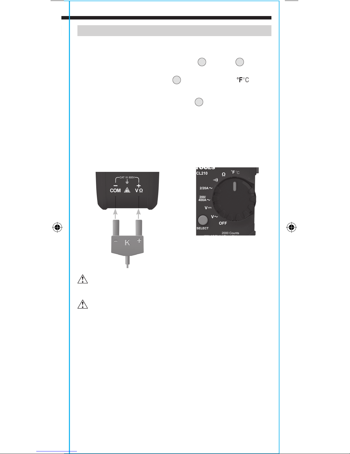
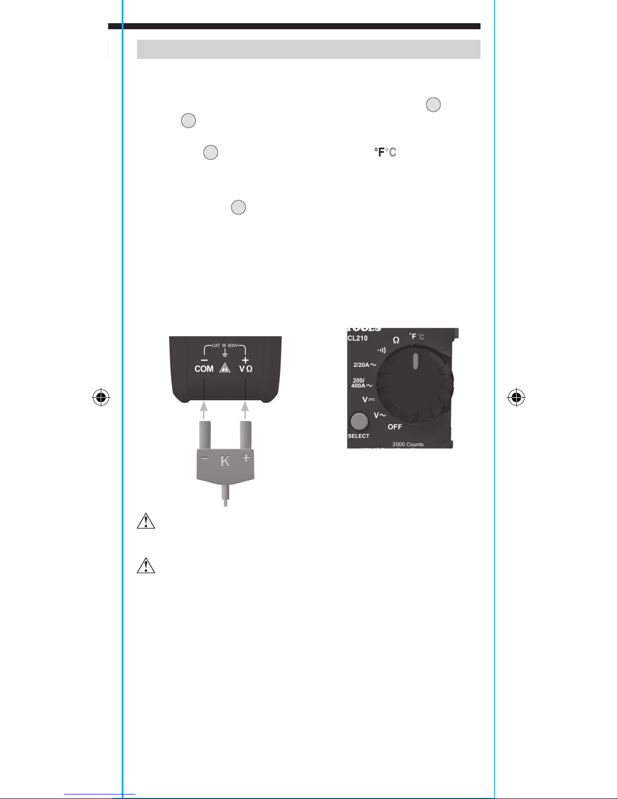
TEMPERATURE
1. Insert K-type thermocouple into the VΩ
(observe polarity markings on thermocouple and meter), and
rotate function selector switch
2
to the Temperature setting.
NOTE: The meter defaults to Fahrenheit scale in this mode. To enter
Celsius scale, press the "SELECT" button
12
appropriate icon (either
°F
or °C) appears on the display.
2. To measure temperature, make contact between the
thermocouple tip and the object being measured. When
thermocouple tip and object are in thermal equilibrium, the
measurement on the display will stabilize. The meter will auto-
range to display the measurement in the most appropriate range.
Remove thermocouple before switching meter to other
measurement functions.
The thermocouple included with the original purchase
is suitable for temperatures below 446°F / 230°C only. To
measure higher temperatures, a K-type thermocouple
with the appropriate measurement range should be used.
ENGLISH
OPERATING INSTRUCTIONS
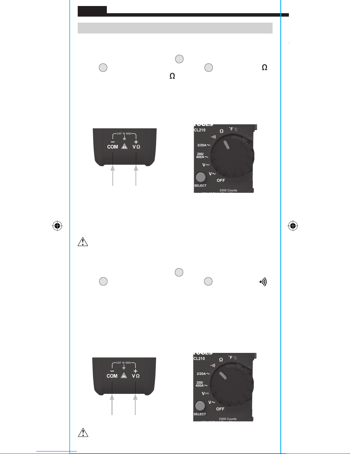
RESISTANCE MEASUREMENTS
1. Insert RED test lead into VΩ jack 5, and BLACK test lead into COM
jack
4
, and rotate function selector switch 2 to the Resistance
setting. The resistance symbol
will appear on the display.
2. Remove power from circuit.
3. Measure resistance by connecting test leads to circuit. The
meter will auto-range to display the measurement in the most
appropriate range.
NOTE: When in a Resistance setting and the test leads are open
(not connected across a resistor), or when a failed resistor is under
test, the display will indicate O.L. This is normal.
DO NOT attempt to measure resistance on a live circuit.
CONTINUITY
1. Insert RED test lead into VΩ jack 5 and BLACK test lead into COM
jack
4
, and rotate function selector switch 2 to the Continuity
setting.
2. Remove power from circuit.
3. Test for continuity by connecting conductor or circuit with test
leads. If resistance is measured less than 10Ω, an audible signal
will sound and display will show a resistance value indicating
continuity. If circuit is open, display will show "OL".
DO NOT attempt to measure continuity on a live circuit.
Red leadBlack lead
Red leadBlack lead
Page 11
11
OPERATING INSTRUCTIONS
TEMPERATURE
1. Insert K-type thermocouple into the VΩ
5
and COM 4 jacks
(observe polarity markings on thermocouple and meter), and
rotate function selector switch
2
to the Temperature setting.
NOTE: The meter defaults to Fahrenheit scale in this mode. To enter
Celsius scale, press the "SELECT" button
12
once. Ensure that the
appropriate icon (either
°F
or °C) appears on the display.
2. To measure temperature, make contact between the
thermocouple tip and the object being measured. When
thermocouple tip and object are in thermal equilibrium, the
measurement on the display will stabilize. The meter will autorange to display the measurement in the most appropriate range.
Remove thermocouple before switching meter to other
measurement functions.
The thermocouple included with the original purchase
is suitable for temperatures below 446°F / 230°C only. To
measure higher temperatures, a K-type thermocouple
with the appropriate measurement range should be used.
K-Type
Thermocouple
Page 12
12
ENGLISH
CLEANING
Be sure meter is turned off and wipe with a clean, dry lint-free
cloth.
Do not use abrasive cleaners or solvents.
STORAGE
Remove the batteries when meter is not in use for a prolonged
period of time. Do not expose to high temperatures or
humidity. After a period of storage in extreme conditions
exceeding the limits mentioned in the General Specifications
section, allow the meter to return to normal operating
conditions before using.
WARRANTY
www.kleintools.com/warranty
DISPOSAL / RECYCLE
Do not place equipment and its accessories in the trash.
Items must be properly disposed of in accordance with local
regulations. Please see www.epa.gov or www.erecycle.org
for additional information.
CUSTOMER SERVICE
KLEIN TOOLS, INC.
450 Bond Street
Lincolnshire, IL 60069
1-877-775-5346
customerservice@kleintools.com
www.kleintools.com
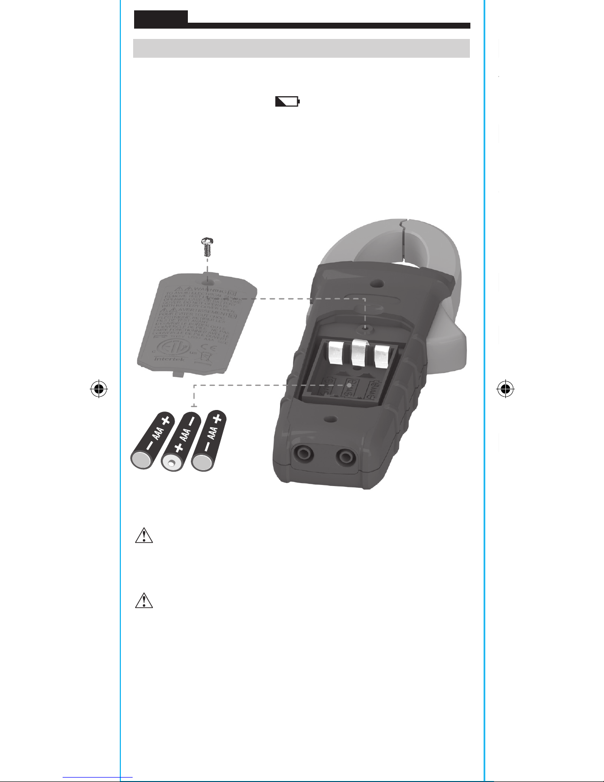
MAINTENANCE
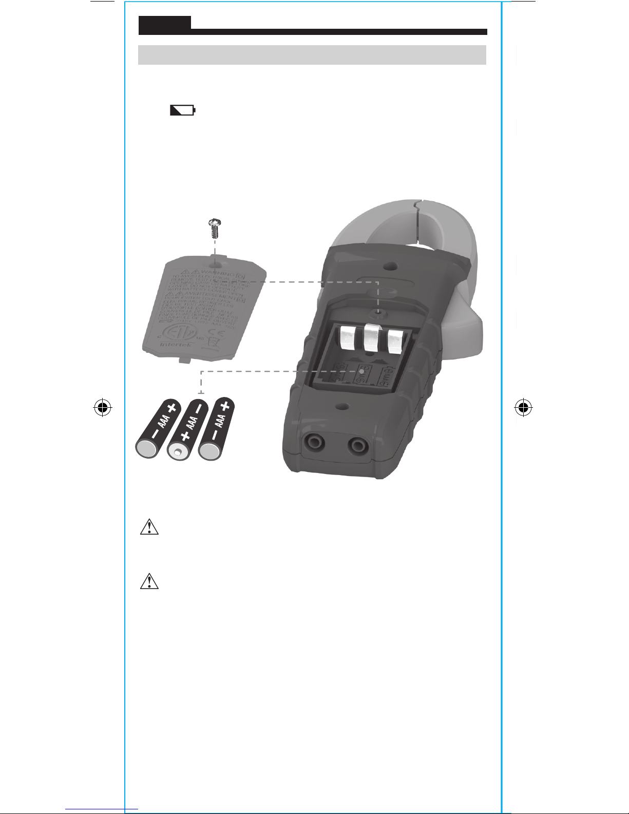
BATTERY REPLACEMENT
When indicator is displayed on LCD, batteries must be replaced.
1. Remove screw from battery door.
2. Replace 3 x AAA batteries (note proper polarity).
3. Replace battery door and fasten securely with screw.
T
o avoid risk of electric shock, disconnect leads from any voltage
source before removing battery door.
To avoid risk of electric shock, do not operate meter while
battery door is removed.
Page 13
CLEANING
Be sure meter is turned off and wipe with a clean, dry lint-free
cloth.
Do not use abrasive cleaners or solvents.
STORAGE
Remove the batteries when meter is not in use for a prolonged
period of time. Do not expose to high temperatures or
humidity. After a period of storage in extreme conditions
exceeding the limits mentioned in the General Specifications
section, allow the meter to return to normal operating
conditions before using.
WARRANTY
www.kleintools.com/warranty
DISPOSAL / RECYCLE
Do not place equipment and its accessories in the trash.
Items must be properly disposed of in accordance with local
regulations. Please see www.epa.gov or www.erecycle.org
for additional information.
CUSTOMER SERVICE
KLEIN TOOLS, INC.
450 Bond Street
Lincolnshire, IL 60069
1-877-775-5346
customerservice@kleintools.com
www.kleintools.com
Page 14
NOTES
ENGLISH
ESPAÑOL
Page 15

MANUAL DE INSTRUCCIONES
CL210
• RANGO AUTOMÁTICO
• RETENCIÓN
DEDATOS
• RETENCIÓN
DERANGO
• TEMPERATURA
• CONTINUIDAD
POR INDICADOR
AUDIBLE
ESPAÑOL
Ω
Multímetro digital
de gancho de rango
automático de 400 A CA
Page 16
16
ESPECIFICACIONES GENERALES
Klein Tools CL210 es un multímetro digital de gancho de rango
automático que mide corriente CA con la pinza, voltaje CA/CD,
resistencia y continuidad con cables de prueba y temperatura con
una sonda de termopar.
• Altitud de funcionamiento: 6562pies (2000m)
• Humedad relativa: <95% sin condensación
• Temperatura de operación: 32°F a 122°F (0°C a 50°C)
• Temperatura de almacenamiento: 14°F a 122°F (-10°C a 50°C)
• Precisión: Valores establecidos según una temperatura ambiente
de 65 °F a 83 °F (18 °C a 28°C)
• Coeciente de temperatura: 0,1 × (precisión indicada) por
cada °C por encima de los 28°C o por debajo de los 18°C, es
necesario realizar correcciones si la temperatura del ambiente de
trabajo se encuentra fuera del rango de precisión de temperatura
• Dimensiones: 8,66" × 3,03" × 1,61"
(220mm × 77mm × 41mm)
• Peso: 9,88oz (280g) incluidas las baterías
• Calibración: precisa durante un año
• Normas: cumple con las siguientes: UL 61010-1,
UL 61010-2-032, UL 61010-2-033.
Certificado según las normas:
CAN/CSA C22.2 N.º61010-1, 61010-2-032,
61010-2-033, IEC EN 61010-1, 61010-2-032,
61010-2-033, IEC EN 61326-1.
• Grado de contaminación: 2
• Precisión: ± (% de lectura + cantidad de dígitos menos
significativos)
• Protección ante caídas: 3,3pies (1m)
• Clasicación de seguridad: CAT III 600V, clase 2,
dobleaislamiento
• Entorno electromagnético: IEC EN 61326-1. Este equipo
cumple con los requisitos apropiados para su uso en entornos
electromagnéticos básicos y controlados como propiedades
residenciales, establecimientos comerciales e instalaciones de
industria ligera.
Especificaciones sujetas a cambios.
ESPECIFICACIONES ELÉCTRICAS
Función Rango Resolución Precisión
Voltaje CA
(V CA)
200,0 mV 0,1 mV ± (2,5% + 10 dígitos)
2,000V 1mV
20,00V 10mV
200,0V 100mV
600V 1V
Voltaje CD
(V CD)
200,0mV 0,1mV ± (1,0% + 8 dígitos)
2,000V 1mV
20,00V 10mV
200,0V 100mV
600V 1V
Impedancia de entrada: 10MΩ
Intervalo de frecuencia: 45Hz a 400Hz
Entrada máxima: 600V CA RMS o 600V CD
Corriente CA
(ACA)
2,000A 1mA
20,00A 10mA
200,0A 100mA
400A 1A
Intervalo de frecuencia: 50Hz a 60Hz
Resistencia
200,0Ω 0,1Ω
2,000kΩ 1Ω
20,00kΩ 10Ω
200,0kΩ 100Ω
2,000MΩ 1kΩ
20,00MΩ 10kΩ
Entrada máxima: 600V CA RMS o 600V CD
Temperatura
-40°F a 1832°F
1°F
-40°C a 1000°C
1
°C ±(2,8% + 6 dígitos)
ESPAÑOL
OTRAS APLICACIONES DE MEDICIÓN
Entrada máxima: 600V CA RMS o 600V CD
• Vericación de continuidad: señal audible < 10Ω, 1,5mA de
corriente máxima
• Frecuencia de muestreo: 3 muestras por segundo
• Apagado automático: después de aprox. 15minutos de inactividad
• Sobrecarga: se indica "OL" en pantalla
• Polaridad: "-" en pantalla indica polaridad negativa
• Pantalla: LCD de 3 ½ dígitos con recuento de 2000
Page 17
17
ESPECIFICACIONES ELÉCTRICAS
Función Rango Resolución Precisión
Voltaje CA
(V CA)
200,0 mV 0,1 mV ± (2,5% + 10 dígitos)
2,000V 1mV
± (2,0% + 5 dígitos)
20,00V 10mV
200,0V 100mV
600V 1V
Voltaje CD
(V CD)
200,0mV 0,1mV ± (1,0% + 8 dígitos)
2,000V 1mV
± (1,0% + 3 dígitos)
20,00V 10mV
200,0V 100mV
600V 1V
Impedancia de entrada: 10MΩ
Intervalo de frecuencia: 45Hz a 400Hz
Entrada máxima: 600V CA RMS o 600V CD
Corriente CA
(ACA)
2,000A 1mA
± (2,5% + 30 dígitos)
20,00A 10mA
± (2,0% + 10 dígitos)
200,0A 100mA
400A 1A
Intervalo de frecuencia: 50Hz a 60Hz
Resistencia
200,0Ω 0,1Ω
± (1,2% + 5 dígitos)
2,000kΩ 1Ω
± (1,2% + 3 dígitos)
20,00kΩ 10Ω
200,0kΩ 100Ω
2,000MΩ 1kΩ
20,00MΩ 10kΩ
± (2,0% + 5 dígitos)
Entrada máxima: 600V CA RMS o 600V CD
Temperatura
-40°F a 1832°F
1°F
≤0°F ±(2,8% + 12 dígitos)
>0°F ±(2,8% + 6 dígitos)
-40°C a 1000°C
1
°C ±(2,8% + 6 dígitos)
OTRAS APLICACIONES DE MEDICIÓN
Entrada máxima: 600V CA RMS o 600V CD
• Vericación de continuidad: señal audible < 10Ω, 1,5mA de
corriente máxima
• Frecuencia de muestreo: 3 muestras por segundo
• Apagado automático: después de aprox. 15minutos de inactividad
• Sobrecarga: se indica "OL" en pantalla
• Polaridad: "-" en pantalla indica polaridad negativa
• Pantalla: LCD de 3 ½ dígitos con recuento de 2000
Page 18

18
ADVERTENCIAS
Para garantizar un funcionamiento y servicio seguros del
multímetro, siga estas instrucciones. El incumplimiento de estas
advertencias puede provocar lesiones graves o la muerte.
• Antes de cada uso, verifique el funcionamiento del multímetro
midiendo un voltaje o corriente conocidos.
• Nunca debe utilizar este multímetro en un circuito con voltajes
que excedan la clasificación basada en categorías del multímetro.
• No utilice el multímetro durante tormentas eléctricas o en clima
húmedo.
• No utilice el multímetro o los cables de prueba si en apariencia
están dañados.
• Utilice el multímetro con cables de prueba con clasificación
CAT III o CAT IV únicamente.
• Asegúrese de que los cables del multímetro estén correctamente
colocados y mantenga los dedos lejos de los contactos de la
sonda de metal al realizar las mediciones.
• No abra el multímetro para reemplazar las baterías mientras las
sondas están conectadas.
• Proceda con precaución cuando trabaje con voltajes superiores
a 25V CA RMS o 60V CD. Esos voltajes implican un riesgo de
descarga.
• Para evitar lecturas falsas que puedan provocar descarga eléctrica,
reemplace las baterías cuando aparezca el indicador de batería baja.
• No intente medir resistencia o continuidad en un circuito activo.
• Cumpla siempre con los códigos de seguridad locales y nacionales.
Utilice equipo de protección personal para prevenir lesiones por
descarga y arco eléctrico en los lugares donde haya conductores
activos peligrosos expuestos.
SÍMBOLOS DEL MULTÍMETRO
CA (corriente alterna) CD (corriente directa)
Resistencia (en ohmios) Continuidad por indicador audible
Doble aislamiento Clase II Conexión a tierra
Advertencia o precaución
Riesgo de choque eléctrico.
V
Voltaje (voltios)
A
Amperaje (amperios)
°F/°
C
Temperatura (Fahrenheit/Celsius)
SÍMBOLOS DE LA PANTALLA LCD
AC
CA (corriente alterna)
DC
CD (corriente directa)
Lectura negativa Retención de datos
Rango automático
MAX
Retención del valor máximo
Batería baja Continuidad por indicador audible
°
F
Grados (Fahrenheit)
°
C
Grados (Celsius)
M
Mega (valor × 106)
k
kilo (valor × 103)
m
mili (valor × 10-3)
V
Voltios
A
Amperios Ohmios
ESPAÑOL
1.
Pantalla LCD con recuento de 20007.Botón "RANGE" ("rango")
2.
Perilla selectora de función
8.
Botón "MAX" ("MÁXIMO")
3.
Pinza
9.
Botón de retención de datos
4.
Conector "COM"
10.
Gatillo de la pinza (presionar
paraabrir la pinza)
5.
Conector "VΩ"
6.
Botón de retroiluminación
11.
Marcas de flechas
12.
Botón "SELECT" ("SELECCIONAR")
NOTA: El multímetro no contiene en su interior piezas que el
usuario pueda reparar.
Page 19

19
DETALLES DE LAS CARACTERÍSTICAS
1
6
2
3
10
12
5
8
7
4
1.
Pantalla LCD con recuento de 20007.Botón "RANGE" ("rango")
2.
Perilla selectora de función
8.
Botón "MAX" ("MÁXIMO")
3.
Pinza
9.
Botón de retención de datos
4.
Conector "COM"
10.
Gatillo de la pinza (presionar
paraabrir la pinza)
5.
Conector "VΩ"
6.
Botón de retroiluminación
11.
Marcas de flechas
12.
Botón "SELECT" ("SELECCIONAR")
11
9
NOTA: El multímetro no contiene en su interior piezas que el
usuario pueda reparar.
Page 20

20
BOTONES DE FUNCIONES
ON/OFF (ENCENDIDO/APAGADO)
Para encender el multímetro, gire la perilla selectora de función
2
de la posición OFF (APAGADO) a cualquier parámetro de medición.
Para apagar el multímetro, gire la perilla selectora de función
2
a la posición OFF (APAGADO). De forma predeterminada, el
multímetro se apagará automáticamente después de 15minutos
de inactividad. Si el multímetro se apaga automáticamente cuando
la perilla selectora de función 2 se encuentra en un parámetro
de medición, gire la perilla a cualquier otra posición (que no sea la
posición OFF [APAGADO]) para volver a encender el multímetro.
BOTÓN "SELECT" ("SELECCIONAR") (PARA FUNCIONES SECUNDARIAS)
El botón "SELECT" 12 sirve para activar la función secundaria del
parámetro de temperatura y alternar entre °F y °C. El parámetro
predeterminado (°F) está impreso en color blanco, y la función
secundaria (°C), en color naranja en el multímetro.
RETROILUMINACIÓN
Presione el botón con el símbolo
6
para encender o apagar la
retroiluminación. La retroiluminación no se apaga automáticamente.
RANGE (RANGO)
El modo predeterminado del multímetro es el de rango automático
. Este modo determina automáticamente el rango de medición
más adecuado para la prueba que se está realizando.
Para que el
multímetro mida en un rango diferente, utilice el botón
"RANGE"
("rango")
7
.
1. Presione el botón "RANGE" ("rango") 7 para seleccionar
manualmente el rango de medición ( desaparece de la
pantalla LCD). Presione el botón "RANGE" ("rango") 7 varias
veces para recorrer los rangos disponibles y deténgase en el
rango deseado.
2. Para volver al modo de rango automático, mantenga presionado
el botón "RANGE" ("rango") 7 durante más de un segundo
( vuelve a aparecer en la pantalla).
MAX (MÁXIMO)
Cuando se presiona el botón "MAX" ("MÁXIMO")
8
, el multímetro
registra el valor máximo a medida que toma las muestras.
1. Mientras mide, presione el botón "MAX" ("MÁXIMO") 8
para visualizar el valor máximo. Si se detecta un valor
máximo nuevo, la pantalla se actualiza con el valor nuevo.
2. Vuelva a presionar el botón "MAX" ("MÁXIMO") 8 para volver al
modo de medición normal.
RETENCIÓN DE DATOS
Presione el botón de retención de datos 9 para retener la medición
en curso en la pantalla. Presione nuevamente para volver al modo
de medición activo.
ESPAÑOL
INSTRUCCIONES DE OPERACIÓN
CONEXIÓN DE LOS CABLES DE PRUEBA
No realice pruebas si los cables no están bien conectados. Los
resultados podrían generar lecturas intermitentes en pantalla. Para
garantizar una buena conexión, presione los cables firmemente en
el conector de entrada hasta el final. El protector del cable debe
quedar al ras de la placa frontal del multímetro.
PRUEBAS EN PUNTOS DE MEDICIÓN CON CLASIFICACIÓN
CAT III/CAT IV
Asegúrese de que el blindaje del cable de prueba esté firmemente
colocado en su lugar. No utilizar el blindaje CAT III/CAT IV aumenta
el riesgo de que se produzca un arco eléctrico.
PRUEBAS EN PUNTOS DE MEDICIÓN CON CLASIFICACIÓN CAT II
Es posible retirar los blindajes CAT III/CAT IV para realizar
mediciones en puntos con clasificación CAT II. Esto permite
efectuar pruebas en conductores empotrados, como
tomacorrientes de pared estándar. Procure no perder los blindajes.
5/32"
(4 mm)
.7" (18 mm)
Page 21

21
INSTRUCCIONES DE OPERACIÓN
CONEXIÓN DE LOS CABLES DE PRUEBA
No realice pruebas si los cables no están bien conectados. Los
resultados podrían generar lecturas intermitentes en pantalla. Para
garantizar una buena conexión, presione los cables firmemente en
el conector de entrada hasta el final. El protector del cable debe
quedar al ras de la placa frontal del multímetro.
PRUEBAS EN PUNTOS DE MEDICIÓN CON CLASIFICACIÓN
CAT III/CAT IV
Asegúrese de que el blindaje del cable de prueba esté firmemente
colocado en su lugar. No utilizar el blindaje CAT III/CAT IV aumenta
el riesgo de que se produzca un arco eléctrico.
PRUEBAS EN PUNTOS DE MEDICIÓN CON CLASIFICACIÓN CAT II
Es posible retirar los blindajes CAT III/CAT IV para realizar
mediciones en puntos con clasificación CAT II. Esto permite
efectuar pruebas en conductores empotrados, como
tomacorrientes de pared estándar. Procure no perder los blindajes.
PRESIONAR
SIN
SEPARACIÓN
5/32"
(4 mm)
.7" (18 mm)
0,7" (18 mm)
Page 22

22
INSTRUCCIONES DE OPERACIÓN
VOLTAJE CA/CD (MENOS DE 600V)
1. Inserte el cable de prueba ROJO en el conector VΩ
cable de prueba NEGRO en el conector COM
selectora de función
2
a la posición de voltaje de CD o
voltaje de CA
. En la pantalla se visualizará "DC" ("CD") o
"AC" ("CA").
2. Aplique los cables de prueba al circuito que se probará para
medir el voltaje. El multímetro seleccionará automáticamente
unrango para mostrar la medición en el rango más adecuado.
NOTA: Si en la pantalla LCD se visualiza "–", los cables de prueba
se están aplicando invertidos al circuito. Invierta la posición de los
cables para solucionar el problema.
NOTA: Cuando el multímetro está configurado para medir voltaje
y los cables de prueba están en circuito abierto, es posible que se
visualicen lecturas del tipo mV en la pantalla. Esto es ruido y es
normal. Al juntar los cables de prueba para cerrar el circuito, la
lectura del multímetro será de cero voltios.
NOTA: Para acceder al rango de mV en la función de voltaje de CA
, se debe utilizar el botón "RANGE" ("rango")
ESPAÑOL
INSTRUCCIONES DE OPERACIÓN
CORRIENTE CA (MENOS DE 400A)
La corriente CA se mide presionando el gatillo de la pinza
10
para
que esta se abra y colocándola alrededor del cable que conduce
la corriente. Al medir, se debe tener cuidado de cerrar bien la
pinza soltando el gatillo
10
por completo, y de que el cable pase
perpendicularmente a través del centro de la pinza y quede alineado
con las marcas de flechas
11
.
Para medir la corriente realice lo siguiente:
1. Gire la perilla selectora de función
2
a la posición de 200/400A.
2. Coloque la pinza alrededor del cable. La medición de corriente
aparecerá en la pantalla.
NOTA: Si el resultado de la medición es inferior a 20A, gire la
perilla selectora de función
2
a la posición de 2/20A para obtener
mejor resolución.
Desconecte los cables de prueba cuando mida con la pinza.
CABLE
Page 23

23
INSTRUCCIONES DE OPERACIÓN
VOLTAJE CA/CD (MENOS DE 600V)
1. Inserte el cable de prueba ROJO en el conector VΩ
5
y el
cable de prueba NEGRO en el conector COM
4
, ygire la perilla
selectora de función
2
a la posición de voltaje de CD o
voltaje de CA
. En la pantalla se visualizará "DC" ("CD") o
"AC" ("CA").
2. Aplique los cables de prueba al circuito que se probará para
medir el voltaje. El multímetro seleccionará automáticamente
unrango para mostrar la medición en el rango más adecuado.
NOTA: Si en la pantalla LCD se visualiza "–", los cables de prueba
se están aplicando invertidos al circuito. Invierta la posición de los
cables para solucionar el problema.
NOTA: Cuando el multímetro está configurado para medir voltaje
y los cables de prueba están en circuito abierto, es posible que se
visualicen lecturas del tipo mV en la pantalla. Esto es ruido y es
normal. Al juntar los cables de prueba para cerrar el circuito, la
lectura del multímetro será de cero voltios.
NOTA: Para acceder al rango de mV en la función de voltaje de CA
, se debe utilizar el botón "RANGE" ("rango")
7.
O
Cable rojoCable negro
Page 24

24
INSTRUCCIONES DE OPERACIÓN
TEMPERATURA
1. Inserte el termopar tipo K en los conectores VΩ
COM
4
(observe las marcas de polaridad en el termopar y
en el multímetro), y gire la perilla selectora de función
posición de temperatura
.
NOTA: La escala de temperatura predeterminada del multímetro
en este modo es Fahrenheit. Para ingresar a la escala en grados
Celsius, presione el botón "SELECT"
12
una vez. Asegúrese de que
aparezca en pantalla el icono correspondiente (
2. Para medir la temperatura, haga que la punta del termopar y el
objeto que se medirá entren en contacto. Cuando la temperatura
de la punta del termopar y la del objeto se hayan equilibrado, se
estabilizará la lectura en la pantalla. El multímetro seleccionará
automáticamente un rango para mostrar la medición en el rango
más adecuado.
Retire el termopar antes de con gurar el multímetro en
otras funciones de medición.
El termopar que viene con el paquete original es apto para
temperaturas inferiores a 446°F / 230°C únicamente.
Para medir temperaturas más elevadas, se debe utilizar un
termopar tipo K con el rango de medición adecuado.
ESPAÑOL
INSTRUCCIONES DE OPERACIÓN
MEDICIÓN DE RESISTENCIA
1. Inserte el cable de prueba ROJO en el conector VΩ 5 y el
cable de prueba NEGRO en el conector COM 4, y gire la perilla
selectora de función 2 a la posición de resistencia . El símbolo
de resistencia aparecerá en la pantalla.
2. Desconecte la energía del circuito.
3. Mida la resistencia conectando los cables de prueba al circuito.
El multímetro seleccionará automáticamente un rango para
mostrar la medición en el rango más adecuado.
NOTA: Cuando el multímetro está configurado para medir
resistencia y los cables de prueba están en circuito abierto (no
conectados a un resistor), o cuando se está probando un resistor
averiado, la pantalla muestra O.L. Esto es normal.
NO intente medir resistencia en un circuito activo.
CONTINUIDAD
1. Inserte el cable de prueba ROJO en el conector VΩ
5
y el cable de
prueba NEGRO en el conector COM 4, y gire la perilla selectora de
función 2 a la posición de continuidad .
2. Desconecte la energía del circuito.
3. Pruebe la continuidad conectando el conductor o el circuito con
los cables de prueba. Si la lectura de la medición de resistencia
es inferior a 10Ω, se oirá una señal audible y en la pantalla se
visualizará un valor de resistencia que indicará la continuidad. Si el
circuito está abierto, aparecerá "OL" en la pantalla.
NO intente medir continuidad en un circuito activo.
Cable rojoCable negro
Cable rojoCable negro
Page 25

25
INSTRUCCIONES DE OPERACIÓN
TEMPERATURA
1. Inserte el termopar tipo K en los conectores VΩ
5
y
COM
4
(observe las marcas de polaridad en el termopar y
en el multímetro), y gire la perilla selectora de función
2
a la
posición de temperatura
.
NOTA: La escala de temperatura predeterminada del multímetro
en este modo es Fahrenheit. Para ingresar a la escala en grados
Celsius, presione el botón "SELECT"
12
una vez. Asegúrese de que
aparezca en pantalla el icono correspondiente (
°F
o °C).
2. Para medir la temperatura, haga que la punta del termopar y el
objeto que se medirá entren en contacto. Cuando la temperatura
de la punta del termopar y la del objeto se hayan equilibrado, se
estabilizará la lectura en la pantalla. El multímetro seleccionará
automáticamente un rango para mostrar la medición en el rango
más adecuado.
Retire el termopar antes de con gurar el multímetro en
otras funciones de medición.
El termopar que viene con el paquete original es apto para
temperaturas inferiores a 446°F / 230°C únicamente.
Para medir temperaturas más elevadas, se debe utilizar un
termopar tipo K con el rango de medición adecuado.
Termopar tipo K
Page 26
26
ESPAÑOL
LIMPIEZA
Asegúrese de que el multímetro esté apagado y límpielo con un
paño limpio, seco, que no deje pelusas.
limpiadores abrasivos.
ALMACENAMIENTO
Retire las baterías si no va a utilizar el multímetro durante
un tiempo prolongado. No lo exponga a la humedad ni a
altas temperaturas. Luego de un período de almacenamiento
en condiciones extremas que sobrepasen los límites
mencionados en la sección Especificaciones generales, deje
que el multímetro vuelva a las condiciones de funcionamiento
normales antes de utilizarlo.
GARANTÍA
www.kleintools.com/warranty
ELIMINACIÓN/RECICLAJE
No arroje el equipo ni sus accesorios a la basura.
Los elementos se deben desechar correctamente
de acuerdo con las regulaciones locales. Para
obtener más información, consulte www.epa.gov
owww.erecycle.org.
SERVICIO AL CLIENTE
KLEIN TOOLS, INC.
450 Bond Street
Lincolnshire, IL 60069, EE.UU.
1-877-775-5346
customerservice@kleintools.com
www.kleintools.com
MANTENIMIENTO
REEMPLAZO DE LAS BATERÍAS
Cuando aparece el indicador en la pantalla LCD, se deben
reemplazar las baterías.
1. Retire el tornillo de la tapa del compartimento de baterías.
2. Reemplace las 3 baterías AAA (observe la polaridad correcta).
3. Vuelva a colocar la puerta del compartimento de baterías y
apriete el tornillo firmemente.
P
ara evitar riesgo de choque eléctrico, desconecte los
cables de toda fuente de voltaje antes de retirar la puerta
delcompartimento de baterías.
Para evitar riesgo de choque eléctrico, no haga funcionar
el multímetro sin colocar la puerta del compartimento de
baterías.
Page 27

LIMPIEZA
Asegúrese de que el multímetro esté apagado y límpielo con un
paño limpio, seco, que no deje pelusas.
No utilice solventes ni
limpiadores abrasivos.
ALMACENAMIENTO
Retire las baterías si no va a utilizar el multímetro durante
un tiempo prolongado. No lo exponga a la humedad ni a
altas temperaturas. Luego de un período de almacenamiento
en condiciones extremas que sobrepasen los límites
mencionados en la sección Especificaciones generales, deje
que el multímetro vuelva a las condiciones de funcionamiento
normales antes de utilizarlo.
GARANTÍA
www.kleintools.com/warranty
ELIMINACIÓN/RECICLAJE
No arroje el equipo ni sus accesorios a la basura.
Los elementos se deben desechar correctamente
de acuerdo con las regulaciones locales. Para
obtener más información, consulte www.epa.gov
owww.erecycle.org.
SERVICIO AL CLIENTE
KLEIN TOOLS, INC.
450 Bond Street
Lincolnshire, IL 60069, EE.UU.
1-877-775-5346
customerservice@kleintools.com
www.kleintools.com
Page 28

NOTAS
ESPAÑOL
FRANÇAIS
Page 29

MANUEL D’UTILISATION
CL210
Multimètre numérique
à pince et à échelle
automatique 400 A c.a.
FRANÇAIS
• ÉCHELLE
AUTOMATIQUE
• MAINTIEN DES
DONNÉES
• CONSERVATION
D'ÉCHELLE
• TEMPÉRATURE
• INDICATEUR SONORE
DE CONTINUITÉ
Ω
Page 30
30
CARACTÉRISTIQUES GÉNÉRALES
Le CL210 de Klein Tools est un multimètre numérique à pince à
détection automatique d’échelle mesurant le courant c.a. à l’aide
d’une pince, la tension c.a./c.c., la résistance et la continuité à l’aide
de fils d’essai et la température à l’aide d’une sonde thermocouple.
• Altitude de fonctionnement: 2000m (6562pi)
• Humidité relative: <95% (sans condensation)
• Température de fonctionnement: 0°C à 50°C (32°F à 122°F)
• Température d’entreposage: -10°C à 50°C (14°F à 122°F)
• Précision:
Valeurs définies entre 18 °C et 28 °C (65 °F et 83 °F)
• Coefcient de température: 0,1 x (précision indiquée) par °C
au-dessus de 28°C ou en dessous de 18°C; des corrections
sont nécessaires lorsque la température ambiante de travail
n’est pas dans la plage de Température de précision
• Dimensions: 220 x 77 x 41mm (8,66 x 3,03 x 1,61po)
• Poids: 280g (9,88oz) en tenant compte des piles
• Étalonnage: Précis pendant un an
• Normes: Conforme aux normes: UL61010-1,
UL61010-2-032, UL61010-2-033.
Certifié conforme aux normes:
CAN/CSAC22.2 no 61010-1, 61010-2-032,
61010-2-033, IECEN61010-1, 61010-2-032,
61010-2-033, IECEN61326-1.
• Niveau de pollution: 2
• Précision: ± (% de la lecture + nombre de chiffres les moins
significatifs)
• Protection contre les chutes: 1m (3,3pi)
• Cote de sécurité: CATIII600V, classe2, double isolation
• Environnement électromagnétique: IECEN61326-1.
Cet équipement répond aux exigences pour une utilisation
dans des environnements électromagnétiques ordinaires
et contrôlés comme les zones résidentielles, les locaux
commerciaux et les sites industriels légers.
Les caractéristiques techniques peuvent faire l’objet de
modifications.
CARACTÉRISTIQUES ÉLECTRIQUES
Fonction Plage Résolution Précision
Tension
c.a.
(Vc.a.)
200,0 mV 0,1 mV ±(2,5% + 10chiffres)
2,000V 1mV
20,00V 10mV
200,0V 100mV
600V 1V
Tension
c.c.
(Vc.c.)
200,0mV 0,1mV ±(1,0% + 8chiffres)
2,000V 1mV
20,00V 10mV
200,0V 100mV
600V 1V
Impédance en entrée: 10MΩ
Plage de fréquences: 45 Hz à 400 Hz
Courant d’entrée maximal: 600V c.a. RMS ou 600V c.c.
Courant c.a.
(Ac.a.)
2,000A 1mA ±(2,5% + 30chiffres)
20,00A 10mA
400A 1A
Plage de fréquences: 50 Hz à 60 Hz
Résistance
200,0Ω 0,1Ω ±(1,2% + 5chiffres)
2,000kΩ 1Ω
20,00kΩ 10Ω
200,0kΩ 100Ω
2,000MΩ 1kΩ
20,00MΩ 10kΩ ±(2,0% + 5chiffres)
Courant d’entrée maximal: 600V c.a. RMS ou 600V c.c.
Température
-40 °C à 1000 °C
1 °C
-40 °F à 1832 °F
1 °F
FRANÇAIS
AUTRES APPLICATIONS DE MESURE
Courant d’entrée maximal: 600V c.a. RMS ou 600V c.c.
• Vérication de continuité: Signal sonore <10Ω,
courantmaximal 1,5mA
• Fréquence d’échantillonnage: 3échantillons par seconde
• Arrêt automatique: Après environ 15minutes d’inactivité
• Surcharge: «OL» indiqué sur l’affichage
• Polarité: «-» sur l’affichage indique une polarité négative
• Afchage: ACL numérique 3½po, 2000lectures
Page 31

31
CARACTÉRISTIQUES ÉLECTRIQUES
Fonction Plage Résolution Précision
Tension
c.a.
(Vc.a.)
200,0 mV 0,1 mV ±(2,5% + 10chiffres)
2,000V 1mV
±(2,0% + 5chiffres)
20,00V 10mV
200,0V 100mV
600V 1V
Tension
c.c.
(Vc.c.)
200,0mV 0,1mV ±(1,0% + 8chiffres)
2,000V 1mV
±(1,0% + 3chiffres)
20,00V 10mV
200,0V 100mV
600V 1V
Impédance en entrée: 10MΩ
Plage de fréquences: 45 Hz à 400 Hz
Courant d’entrée maximal: 600V c.a. RMS ou 600V c.c.
Courant c.a.
(Ac.a.)
2,000A 1mA ±(2,5% + 30chiffres)
20,00A 10mA
±(2,0% + 10chiffres)200,0A 100mA
400A 1A
Plage de fréquences: 50 Hz à 60 Hz
Résistance
200,0Ω 0,1Ω ±(1,2% + 5chiffres)
2,000kΩ 1Ω
±(1,2% + 3chiffres)
20,00kΩ 10Ω
200,0kΩ 100Ω
2,000MΩ 1kΩ
20,00MΩ 10kΩ ±(2,0% + 5chiffres)
Courant d’entrée maximal: 600V c.a. RMS ou 600V c.c.
Température
-40 °C à 1000 °C
1 °C
>0° ±(2,8% + 6chiffres)
-40 °F à 1832 °F
1 °F
≤0°F ±(2,8% + 12chiffres)
>0°F ±(2,8% + 6chiffres)
AUTRES APPLICATIONS DE MESURE
Courant d’entrée maximal: 600V c.a. RMS ou 600V c.c.
• Vérication de continuité: Signal sonore <10Ω,
courantmaximal 1,5mA
• Fréquence d’échantillonnage: 3échantillons par seconde
• Arrêt automatique: Après environ 15minutes d’inactivité
• Surcharge: «OL» indiqué sur l’affichage
• Polarité: «-» sur l’affichage indique une polarité négative
• Afchage: ACL numérique 3½po, 2000lectures
Page 32

32
AVERTISSEMENTS
Pour garantir une utilisation et un entretien du multimètre
sécuritaires, suivez ces instructions. Le non-respect de ces
avertissements peut entraîner des blessures graves, voire la mort.
• Avant chaque utilisation, vérifiez le fonctionnement du multimètre en
mesurant une tension ou un courant de valeur connue.
• N’utilisez jamais le multimètre sur un circuit dont la tension dépasse
la tension correspondant à la cote de sécurité de l’appareil.
• N'utilisez pas le multimètre lors d'orages électriques ou par temps
humide.
• N’utilisez pas le multimètre ou les fils d’essai s’ils semblent avoir
étéendommagés.
• Utilisez uniquement des fils d’essai conformes à la norme CAT III ou CAT IV.
• Assurez-vous que les fils d’essai sont bien installés et évitez de
toucher les contacts métalliques des sondes lors de la mesure.
• N'ouvrez pas le multimètre pour remplacer les piles lorsque les
sondes sont connectées.
• Faites preuve de prudence lors de mesures sur des circuits de plus
de 25V c.a. RMS ou de 60V c.c. De telles tensions constituent un
risque d’électrocution.
• Pour éviter les lectures faussées pouvant provoquer une électrocution,
remplacez les piles lorsque l'indicateur de piles faibles apparaît.
• Ne tentez pas de mesurer la résistance ou la continuité sur un circuit
alimenté en électricité.
• Assurez-vous de respecter en tout temps les codes de sécurité
locaux et nationaux. Utilisez de l’équipement de protection
individuelle pour prévenir l’électrocution et les blessures causées
par les arcs électriques lorsque des conducteurs nus alimentés
potentiellement dangereux sont présents.
SYMBOLES SUR LE MULTIMÈTRE
C.A. (courant alternatif) C.C. (courant continu)
Résistance (en ohms) Indicateur sonore de continuité
Double isolation, Classe II Mise à la masse
Avertissement ou mise en garde
Risque de choc électrique
V
Tension (volts)
A
Ampérage (A)
°F/°
C
Température (Fahrenheit/Celsius)
SYMBOLES À L’AFFICHAGE ACL
AC
C.A. (courant alternatif)
DC
C.C. (courant continu)
Lecture négative Maintien des données
Sélection automatique
del'échelle
MAX
Maintien de la valeur maximale
Pile faible Indicateur sonore de continuité
°
F
Degrés (Fahrenheit)
°
C
Degrés (Celsius)
M
Méga (valeur x 106)
k
kilo (valeur x 103)
m
milli (valeur x 10-3)
V
Volts
A
Ampères Ohms
FRANÇAIS
1. Affichage ACL jusqu’à 2000lectures 7. Bouton RANGE (Échelle)
2.
Commutateur de sélection de fonctions
8. Bouton MAX (Maximum)
3. Pince 9. Bouton HOLD (Maintien des
données)
4. FicheCOM 10.
Gâchette de pince (appuyer pour
ouvrir la pince)
5. Fiche VΩ 11. Marquages de flèche
6. Bouton de rétroéclairage 12. Bouton SELECT (Sélection)
REMARQUE: Ce multimètre ne contient aucune pièce réparable.
Page 33

33
CARACTÉRISTIQUES DÉTAILLÉES
1
6
2
3
10
12
5
8
7
4
1. Affichage ACL jusqu’à 2000lectures 7. Bouton RANGE (Échelle)
2.
Commutateur de sélection de fonctions
8. Bouton MAX (Maximum)
3. Pince 9. Bouton HOLD (Maintien des
données)
4. FicheCOM 10.
Gâchette de pince (appuyer pour
ouvrir la pince)
5. Fiche VΩ 11. Marquages de flèche
6. Bouton de rétroéclairage 12. Bouton SELECT (Sélection)
11
9
REMARQUE: Ce multimètre ne contient aucune pièce réparable.
Page 34

34
BOUTONS DE FONCTION
ON/OFF (MARCHE/ARRÊT)
Pour allumer le multimètre, tournez le commutateur de sélection
de fonctions
2
du réglage OFF à tout autre réglage de mesure.
Pour éteindre le multimètre, tournez le commutateur de sélection
de fonctions
2
vers le réglage OFF. Par défaut, l’appareil s’éteint
automatiquement après 15minutes d’inactivité. Si le multimètre
s’éteint automatiquement lorsqu’un réglage de mesure est sélectionné,
tournez le commutateur de sélection de fonctions
2
vers tout autre
réglage (à l’exception du réglage OFF) pour allumer l’appareil.
BOUTON SELECT (SÉLECTION) (POUR LES FONCTIONS SECONDAIRES)
Le bouton SELECT 12 active la fonction secondaire pour le réglage
de température et permet de basculer entre °F et °C. Le réglage
par défaut (°F) est imprimé en blanc sur le multimètre; le réglage
secondaire (°C) est imprimé en orange.
RÉTROÉCLAIRAGE
Appuyez sur le bouton avec le symbole de rétroéclairage
6
pour
activer ou désactiver le rétroéclairage. Le rétroéclairage ne s’éteint
pas automatiquement.
RANGE (ÉCHELLE)
Par défaut, le multimètre est en mode échelle automatique
.
Ce mode automatique détermine l’échelle la plus appropriée pour
les mesures effectuées.
Pour forcer le multimètre à effectuer des
mesures en utilisant une autre échelle, utilisez le bouton Range
7
.
1. Appuyez sur le bouton RANGE 7 pour sélectionner manuellement
l’échelle (
est désactivé sur l’affichage ACL). Appuyez sur le
bouton RANGE
7
à plusieurs reprises pour parcourir les échelles
disponibles et arrêtez lorsque vous avez atteint la plage souhaitée.
2. Pour retourner en mode échelle automatique, appuyez sur le
bouton RANGE
7
pendant plus d’une seconde ( est réactivé).
MAX
Lorsque le bouton MAX
8
est enfoncé, le multimètre mémorise la
valeur maximale tout en continuant à faire des lectures.
1. Pendant la mesure, appuyez sur le bouton MAX
8
pour
afficher la valeur maximale. Si une nouvelle valeur maximale est
mesurée, l’affichage est actualisé et affiche la nouvelle valeur.
2. Appuyez de nouveau sur le bouton MAX 8 pour revenir au mode
de lecture normal.
HOLD (MAINTIEN DES DONNÉES)
Appuyez sur le bouton HOLD (Maintien des données)
9
pour que
la lecture actuelle demeure affichée. Appuyez de nouveau pour
retourner au mode de lecture en temps réel.
FRANÇAIS
INSTRUCTIONS D’UTILISATION
BRANCHEMENT DES FILS D’ESSAI
N’effectuez pas de test si les fils d’essai ne sont pas installés
correctement. Cela pourrait causer des lectures intermittentes.
Pourassurer un raccordement approprié, enfoncez complètement
les fils d’essai dans la prise d’entrée. Le protecteur du fil d’essai
doit être en contact avec la face avant du multimètre.
EFFECTUER DES TESTS DANS DES EMPLACEMENTS CATIII/CATIV
Assurez-vous que l’écran de protection des fils d’essai est enfoncé
complètement. Le fait de ne pas utiliser l’écran de protection
CATIII/CATIV augmente le risque d’arc électrique.
EFFECTUER DES TESTS DANS DES EMPLACEMENTS CATII
Les écrans de protection CATIII/CATIV peuvent être retirés dans
les emplacements CATII. Cela permet d’effectuer des tests sur des
conducteurs encastrés, par exemple les prises murales standard.
Assurez-vous de ne pas perdre les écrans de protection.
.7" (18 mm)
5/32"
(4 mm)
Page 35

35
INSTRUCTIONS D’UTILISATION
BRANCHEMENT DES FILS D’ESSAI
N’effectuez pas de test si les fils d’essai ne sont pas installés
correctement. Cela pourrait causer des lectures intermittentes.
Pourassurer un raccordement approprié, enfoncez complètement
les fils d’essai dans la prise d’entrée. Le protecteur du fil d’essai
doit être en contact avec la face avant du multimètre.
EFFECTUER DES TESTS DANS DES EMPLACEMENTS CATIII/CATIV
Assurez-vous que l’écran de protection des fils d’essai est enfoncé
complètement. Le fait de ne pas utiliser l’écran de protection
CATIII/CATIV augmente le risque d’arc électrique.
EFFECTUER DES TESTS DANS DES EMPLACEMENTS CATII
Les écrans de protection CATIII/CATIV peuvent être retirés dans
les emplacements CATII. Cela permet d’effectuer des tests sur des
conducteurs encastrés, par exemple les prises murales standard.
Assurez-vous de ne pas perdre les écrans de protection.
APPUYER
AUCUN
ESPACE
.7" (18 mm)
18 mm (0,7 po)
5/32"
(4 mm)
4 mm
(5/32 po)
Page 36

36
INSTRUCTIONS D’UTILISATION
COURANT C.A./C.C. (INFÉRIEUR À 600V)
1. Insérez le fil d’essai ROUGE dans la prise VΩ
NOIR dans la prise COM
4
, puis tournez le commutateur de
sélection de fonctions
2
pour sélectionner le réglage Tension
c.c.
ou Tension c.a. . Remarquez DC (c.c.) ou AC (c.a.)
affiché à l’écran.
2. Appliquez les fils d’essai au circuit à tester pour mesurer la
tension. Le multimètre choisira l’échelle automatiquement
pourafficher la mesure dans l’échelle la plus appropriée.
REMARQUE: Si «–» apparaît sur l’affichage ACL, les fils
d’essaisont appliqués au circuit selon la polarité inverse.
Inversezla position des fils pour corriger cette situation.
REMARQUE: Lorsqu’une fonction de test de tension est
sélectionnée et les fils d’essai forment un circuit ouvert, des
lectures de l’ordre du mV peuvent apparaître à l’écran. Il s’agit
debruit normal. En mettant les fils d’essai en contact pour
fermerle circuit, le multimètre mesurera zéro volt.
REMARQUE: Pour accéder à l’échelle mV pour la tension c.a.
le bouton RANGE
7 doit être utilisé.
FRANÇAIS
INSTRUCTIONS D’UTILISATION
COURANT C.A. (INFÉRIEUR À 400A)
Le courant c.a. est mesuré en appuyant sur la gâchette de la pince
10
pour ouvrir la pince et en la plaçant autour d’un fil sous tension.
Lors de la mesure, il faut veiller à ce que la pince soit complètement
fermée et la gâchette complètement relâchée
10
; le fil doit passer
perpendiculairement à travers le centre de la pince, aligné avec les
flèches
11
.
Pour mesurer le courant:
1. Tournez le commutateur de sélection de fonctions
2
pour
sélectionner le réglage 200/400A.
2. Placez la pince autour du fil. La mesure du courant apparaît sur
l’affichage de l’appareil.
REMARQUE: Si la mesure est inférieure à 20A, tournez le
commutateur de sélection de fonctions
2
pour sélectionner la
réglage 2/20A afin d’augmenter la résolution.
Débranchez les ls d’essai lorsque vous faites des mesures
avec la pince.
FIL
Page 37

37
INSTRUCTIONS D’UTILISATION
COURANT C.A./C.C. (INFÉRIEUR À 600V)
1. Insérez le fil d’essai ROUGE dans la prise VΩ
5
et le fil d’essai
NOIR dans la prise COM
4
, puis tournez le commutateur de
sélection de fonctions
2
pour sélectionner le réglage Tension
c.c.
ou Tension c.a. . Remarquez DC (c.c.) ou AC (c.a.)
affiché à l’écran.
2. Appliquez les fils d’essai au circuit à tester pour mesurer la
tension. Le multimètre choisira l’échelle automatiquement
pourafficher la mesure dans l’échelle la plus appropriée.
REMARQUE: Si «–» apparaît sur l’affichage ACL, les fils
d’essaisont appliqués au circuit selon la polarité inverse.
Inversezla position des fils pour corriger cette situation.
REMARQUE: Lorsqu’une fonction de test de tension est
sélectionnée et les fils d’essai forment un circuit ouvert, des
lectures de l’ordre du mV peuvent apparaître à l’écran. Il s’agit
debruit normal. En mettant les fils d’essai en contact pour
fermerle circuit, le multimètre mesurera zéro volt.
REMARQUE: Pour accéder à l’échelle mV pour la tension c.a.
,
le bouton RANGE
7 doit être utilisé.
OU
Fil rougeFil noir
Page 38

38
INSTRUCTIONS D’UTILISATION
TEMPÉRATURE
1. Insérez le thermocouple de typeK dans les prises VΩ
COM
4
(respectez la polarité indiquée sur le thermocouple
et lemultimètre) et tournez le commutateur de sélection de
fonctions
2
jusqu’au réglage Température .
REMARQUE: Dans ce mode, le multimètre se met par défaut à
l’échelle Fahrenheit. Pour passer à l’échelle Celsius, appuyez sur
lebouton SELECT
12
une fois. Assurez-vous que l’icône appropriée
(
°F
ou °C) s’affiche.
2. Pour mesurer la température, touchez l’objet mesuré avec la
pointe du thermocouple. Lorsque la pointe du thermocouple
et l’objet sont en équilibre thermique, la mesure à l’écran se
stabilise. Le multimètre choisira l’échelle automatiquement
pourafficher la mesure dans l’échelle la plus appropriée.
Retirez le thermocouple avant de sélectionner une autre
fonction du multimètre.
Le thermocouple livré avec l’appareil permet de mesurer
des températures inférieures à 230°C/446°F seulement.
Pour mesurer des températures plus élevées, un
thermocouple de typeK devrait être utilisé avec l’échelle
de températures appropriée.
FRANÇAIS
INSTRUCTIONS D’UTILISATION
MESURES DE RÉSISTANCE
1. Insérez le fil d’essai ROUGE dans la prise VΩ 5 et le fil d’essai
NOIR dans la prise COM 4, puis tournez le commutateur de
sélection de fonctions 2 pour sélectionner le réglage Résistance
. Le symbole de résistance apparaît.
2. Coupez l’alimentation du circuit.
3. Mesurez la résistance en connectant les fils d’essai de part et
d’autre du circuit. Le multimètre choisira l’échelle automatiquement
pour afficher la mesure dans l’échelle la plus appropriée.
REMARQUE: Lorsqu’une fonction de test de résistance est
sélectionnée et les fils d’essai ne sont pas en contact (ils ne sont
pas connectés de part et d’autre d’une résistance), ou encore,
lorsqu’une résistance défectueuse est testée, l’écran affiche
«O.L.». Cela est normal.
NE tentez PAS de mesurer la résistance sur un circuit
alimenté en électricité.
CONTINUITÉ
1. Insérez le fil d’essai ROUGE dans la prise VΩ
5
et le fil d’essai
NOIR dans la prise COM 4, puis tournez le commutateur de
sélection de fonctions 2 pour sélectionner le réglage Continuité .
2. Coupez l’alimentation du circuit.
3. Testez la continuité en connectant un conducteur ou un circuit
aux fils d’essai. Si la résistance mesurée est inférieure à 10Ω,
un signal sonore et l’affichage indiquent une valeur de résistance
correspondant à la continuité. Si le circuit est ouvert, l’affichage
indique «OL».
NE tentez PAS de mesurer la continuité sur un circuit
alimenté en électricité.
Fil rougeFil noir
Fil rougeFil noir
Page 39
39
INSTRUCTIONS D’UTILISATION
TEMPÉRATURE
1. Insérez le thermocouple de typeK dans les prises VΩ
5
et
COM
4
(respectez la polarité indiquée sur le thermocouple
et lemultimètre) et tournez le commutateur de sélection de
fonctions
2
jusqu’au réglage Température .
REMARQUE: Dans ce mode, le multimètre se met par défaut à
l’échelle Fahrenheit. Pour passer à l’échelle Celsius, appuyez sur
lebouton SELECT
12
une fois. Assurez-vous que l’icône appropriée
(
°F
ou °C) s’affiche.
2. Pour mesurer la température, touchez l’objet mesuré avec la
pointe du thermocouple. Lorsque la pointe du thermocouple
et l’objet sont en équilibre thermique, la mesure à l’écran se
stabilise. Le multimètre choisira l’échelle automatiquement
pourafficher la mesure dans l’échelle la plus appropriée.
Retirez le thermocouple avant de sélectionner une autre
fonction du multimètre.
Le thermocouple livré avec l’appareil permet de mesurer
des températures inférieures à 230°C/446°F seulement.
Pour mesurer des températures plus élevées, un
thermocouple de typeK devrait être utilisé avec l’échelle
de températures appropriée.
Thermocouple
detypeK
Page 40

40
FRANÇAIS
NETTOYAGE
Assurez-vous d’éteindre le multimètre, puis essuyez-le à l’aide
d’un linge non pelucheux propre.
N’utilisez pas de nettoyant
abrasif ou de solvant.
RANGEMENT
Retirez les piles lorsque vous prévoyez ne pas utiliser le
multimètre pendant une longue période. N’exposez pas
l’appareil à des températures élevées ou à un taux d’humidité
élevé. Après une période de stockage dans des conditions
extrêmes (hors des limites mentionnées dans la section
Caractéristiques générales), laissez le multimètre revenir
àdesconditions d’utilisation normales avant de l’utiliser.
GARANTIE
www.kleintools.com/warranty
MISE AU REBUT/RECYCLAGE
Ne pas mettre l’appareil et ses accessoires au rebut.
Ces articles doivent être éliminés conformément aux
règlements locaux. Pour de plus amples renseignements,
consultez les sites www.epa.gov ou www.erecycle.org.
SERVICE À LA CLIENTÈLE
KLEIN TOOLS, INC.
450 Bond Street
Lincolnshire, IL 60069
1-877-775-5346
customerservice@kleintools.com
www.kleintools.com
ENTRETIEN
REMPLACEMENT DES PILES
Lorsque l’indicateur est affiché à l’écran ACL, il est nécessaire
de remplacer les piles.
1. Retirez la vis de la porte du compartiment à piles.
2. Remplacez les 3piles AAA (tenez compte de la polarité).
3. Replacez la porte du compartiment à piles et fixez-la solidement
à l’aide de la vis.
P
our éviter le risque d’électrocution, débranchez les ls
d’essai de toute source de tension avant de retirer la porte
ducompartiment à piles.
Pour éviter le risque d’électrocution, n’utilisez pas le
multimètre lorsque la porte du compartiment à piles
estretirée.
Page 41

NETTOYAGE
Assurez-vous d’éteindre le multimètre, puis essuyez-le à l’aide
d’un linge non pelucheux propre.
N’utilisez pas de nettoyant
abrasif ou de solvant.
RANGEMENT
Retirez les piles lorsque vous prévoyez ne pas utiliser le
multimètre pendant une longue période. N’exposez pas
l’appareil à des températures élevées ou à un taux d’humidité
élevé. Après une période de stockage dans des conditions
extrêmes (hors des limites mentionnées dans la section
Caractéristiques générales), laissez le multimètre revenir
àdesconditions d’utilisation normales avant de l’utiliser.
GARANTIE
www.kleintools.com/warranty
MISE AU REBUT/RECYCLAGE
Ne pas mettre l’appareil et ses accessoires au rebut.
Ces articles doivent être éliminés conformément aux
règlements locaux. Pour de plus amples renseignements,
consultez les sites www.epa.gov ou www.erecycle.org.
SERVICE À LA CLIENTÈLE
KLEIN TOOLS, INC.
450 Bond Street
Lincolnshire, IL 60069
1-877-775-5346
customerservice@kleintools.com
www.kleintools.com
Page 42

REMARQUES
FRANÇAIS
Page 43

REMARQUES
Page 44

1390114 Rev 08/15 C
KLEIN TOOLS, INC.
450 Bond Street
Lincolnshire, IL 60069
1-877-775-5346
customerservice@kleintools.com
www.kleintools.com
 Loading...