

Page 1

ENGLISH
MM300
INSTRUCTION MANUAL
• DATA HOLD
• AUDIBLE
CONTINUITY
• BATTERY TEST
• DIODE TEST
Ω
Find Quality Products Online at: [email protected]
www.GlobalTestSupply.com
Page 2

ENGLISH
GENERAL SPECIFICATIONS
Klein Tools MM300 is a manual ranging multimeter that measures
AC/DC voltage, DC current, and resistance. It can also test batteries,
diodes, and continuity.
• Operating Altitude: 6562 ft. (2000m)
Relative Humidity: <80% non-condensing
•
• Operating Temp: 32°F to 104°F (0°F to 40°C)
Storage Temp: 14°C to 140°F (-10°C to 60°C)
•
•
Accuracy: Values stated at 65° to 83°F (18° to 28°C)
Temp Coef cient: 0.1 x (Quoted Accuracy) per °
•
°C or below 18°
28
working temp is outside of Accuracy T
•
Dimensions: 6.04" x 3.07" x 1.78" (153.4 x 78.0 x 45.2 mm)
C, corrections are required when ambient
emp range
C above
Weight: 8.1 oz. (230 g)
•
•
Calibration: Accurate for one year
Standards: Conforms to: UL STD 61010-1, 61010-2-030,
•
61010-2-033.
Certified to: CSA STD C22.2 # 61010-1,
61010-2-030, 61010-2-033.
IEC EN 61010-1, 61010-2-030,
61010-2-033, 61326-1.
• Pollution degree: 2
Accuracy: ± (% of reading + # of least significant digits)
•
• Drop Protection: 3.3 ft. (1m)
•
Safety Rating: CAT III 600V, Class 2, Double insulation
CAT III: Measurement category III is applicable to test and
measuring circuits connected to the distribution part of the
building’s low-voltage MAINS installation.
• Electromagnetic Environment: IEC EN 61326-1. This
equipment meets requirements for use in basic and controlled
electromagnetic environments like residential properties,
business premises, and light-industrial locations.
Specifications subject to change.
Find Quality Products Online at: [email protected]
2
www.GlobalTestSupply.com
Page 3
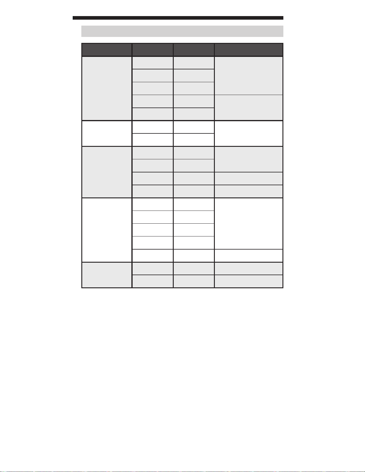
ELECTRICAL SPECIFICATIONS
Function Range Resolution Accuracy
200.0mV 0.1mV
±(0.5% + 3 digits)2000mV 1mV
DC Voltage
(V DC)
20.00V 0.01V
200.0V 0.1V
±(0.8% + 3 digits)
600V 1V
AC Voltage
(V AC)
DC Current
(A DC)
Resistance
Battery Test
200.0V 0.1V
600V 1V
200.0μA 0.1μA
20.00mA 10μA
200.0mA 100μA ±(1.2% + 5 digits)
10.00A 10mA ±(3.0% + 5 digits)
200.0Ω 0.1Ω
2000Ω 1Ω
20.00kΩ 0.01kΩ
200.0kΩ 0.1kΩ
2000kΩ 1kΩ ±(1.5% + 5 digits)
9V 10mV ±(1.0% + 2 digits)
1.5V 10mV ±(1.0% + 2 digits)
±(1.2% + 10 digits)
50 to 60Hz
±(1.0% + 5 digits)
±(1.0% + 5 digits)
• Diode Test: Approx. 1mA, open circuit voltage 2.0V DC
• Continuity Check: Audible signal <100Ω
• Battery Test: 9V (6mA); 1.5V (100mA)
• Sampling Frequency: 2 samples per second
• Overload: "OL" indicated on display, overload protection
600V RMS in all settings
• Polarity: "-" on display indicates negative polarity
• Display: 3 ½ digit, 2000 Count LCD
Find Quality Products Online at: [email protected]
www.GlobalTestSupply.com
3
Page 4
ENGLISH
WARNINGS
To ensure safe operation and service of the meter, follow these
instructions. Failure to observe these warnings can result in
severe injury or death.
• Before each use verify meter operation by measuring a known
voltage or current.
•
Never use the meter on a cir
categor
y based rating of this meter.
cuit with voltages that exceed the
• Do not use the meter during electrical storms or in wet weather.
• Do not use the meter or test leads if they appear to be damaged.
• Use only with CA
T III or CAT IV rated test leads.
• Ensure meter leads are fully seated, and keep fingers away
from the metal probe contacts when making measurements.
• Do not open the meter to replace batteries while the probes
are connected.
• Use caution when working with voltages above 25V AC RMS
or 60V DC. Such voltages pose a shock hazard.
•To avoid false readings that can lead to electrical shock,
replace batteries when a low batter
y indicator appears.
• Do not attempt to measure resistance or continuity on a live
circuit.
• Always adhere to local and national safety codes. Use personal
protective equipment to prevent shock and ar
c blast injur
y
where hazardous live conductors are exposed.
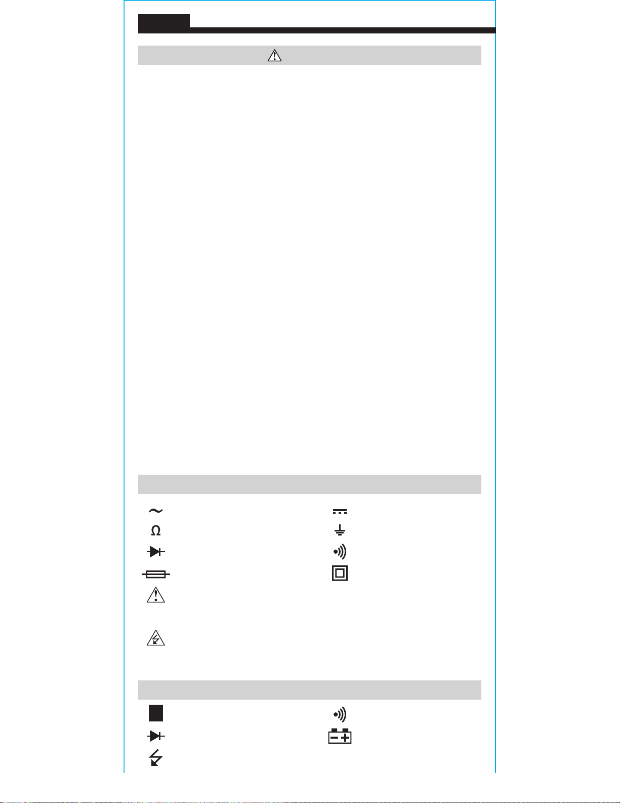
SYMBOLS ON METER
AC (Alternating Current) DC (Direct Current)
Resistance (in Ohms) Ground
Diode Audible Continuity
Fuse (with rating below symbol) Double Insulated Class II
Warning or Caution
To ensure safe operation and service of this meter, follow all
warnings and instructions detailed in this manual.
Risk of Electrical Shock
Improper use of this meter can lead to risk of electrical shock. Follow
all warnings and instructions detailed in this manual.
SYMBOLS ON LCD
Data Hold Audible Continuity
H
Diode Low Battery
Dangerous levels
Find Quality Products Online at: [email protected]
4
www.GlobalTestSupply.com
Page 5
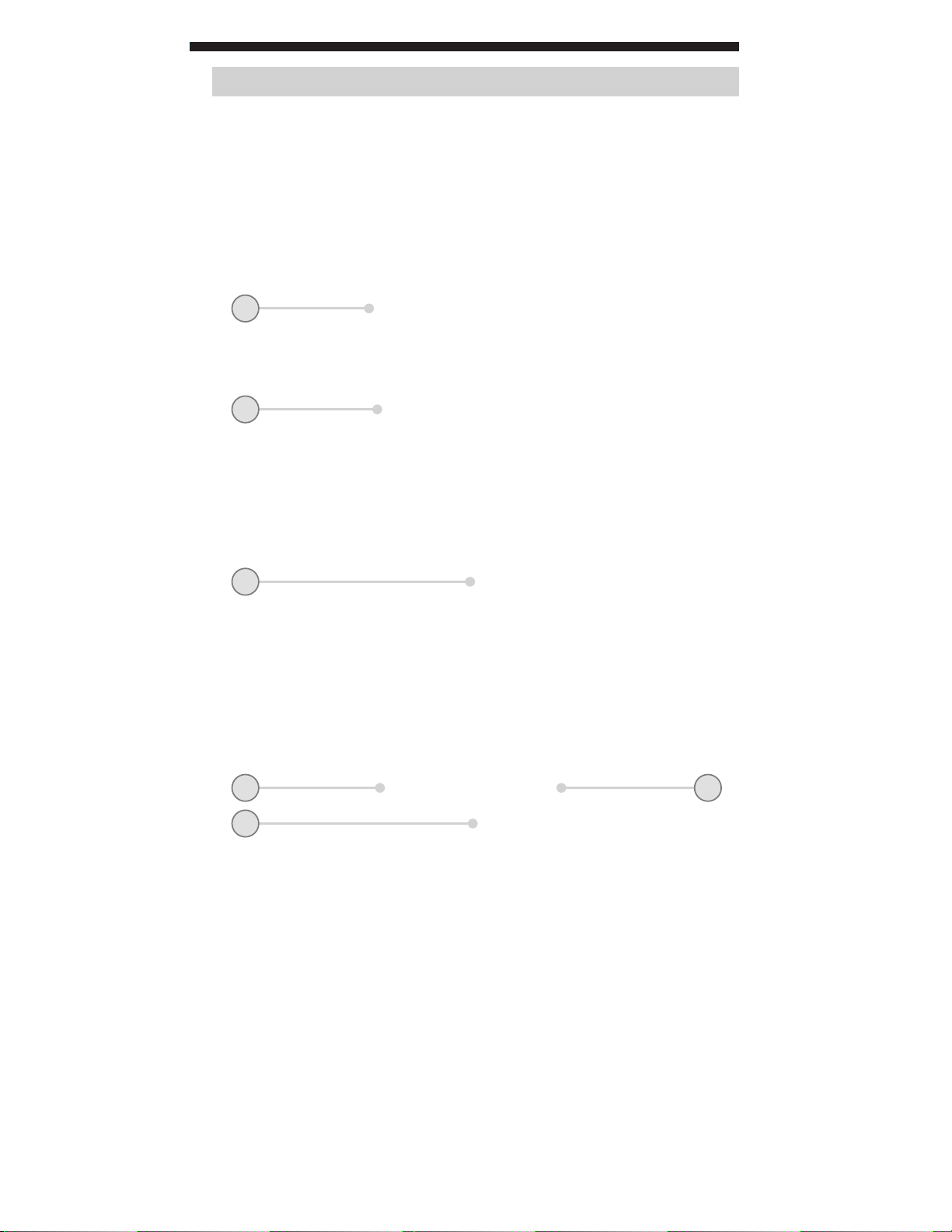
FEATURE DETAILS
1
6
2
3 5
4
NOTE: There are no user-serviceable parts inside meter.
2000 count LCD display
1.
Function selector switch
2.
"10A" jack
3.
"COM" jack
4.
"VΩ" jack
5.
"HOLD" (Data Hold) button
6.
Find Quality Products Online at: [email protected]
www.GlobalTestSupply.com
5
Page 6
ENGLISH
OPERATING INSTRUCTIONS
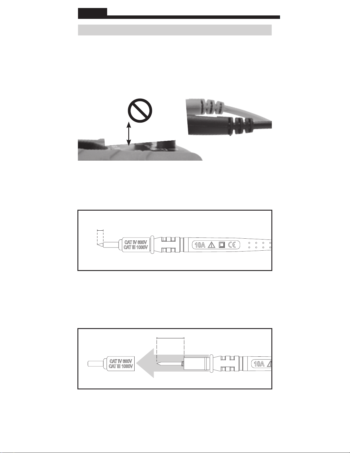
CONNECTING TEST LEADS
Do not test if leads are improperly seated. Results could cause
intermittent display readings. To ensure proper connection, firmly
press leads into the input jack completely.
INCORRECT
CORRECT
TESTING IN CAT III / CAT IV MEASUREMENT LOCATIONS
Ensure the test lead shield is pressed firmly in place. Failure to use
the CAT III / CAT IV shield increases arc-flash risk.
5/32"
(4 mm)
TESTING IN CAT II MEASUREMENT LOCATIONS
CAT III / CAT IV shields may be removed for CAT II locations. This
will allow testing on recessed conductors such as standard wall
outlets. Take care not to lose the shields.
.7" (18 mm)
Find Quality Products Online at: [email protected]
6
www.GlobalTestSupply.com
Page 7
OPERATING INSTRUCTIONS
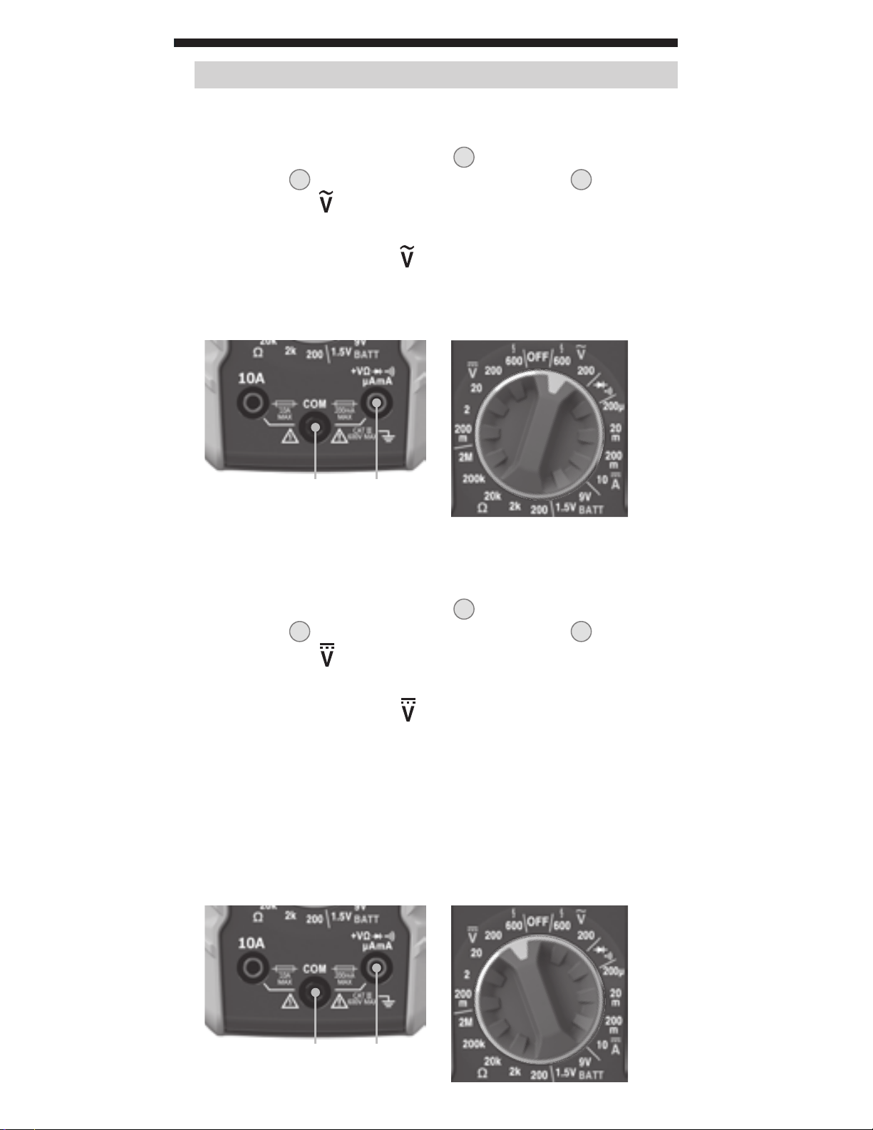
AC VOLTAGE (LESS THAN 600V)
1.
Insert RED test lead into VΩ jack
COM jack
highest V AC (
, and rotate function selector switch 2 to the
4
) setting (600V).
, and BLACK test lead into
5
2. Measure voltage and rotate the function selector switch to
successively lower V AC (
) settings to obtain higher resolution
measurements.
NOTE: Do not attempt to measure more than 600V or 200mA.
Red leadBlack lead
DC VOLTAGE (LESS THAN 600V)
Insert RED test lead into VΩ jack
1.
COM jack
highest V DC (
, and rotate function selector switch 2 to the
4
) setting (600V).
, and BLACK test lead into
5
2. Measure voltage and rotate the function selector switch to
successively lower V DC (
) settings to obtain higher resolution
measurements.
NOTE: When in a voltage setting and the test leads are open,
readings of order mV may appear on the display. This is noise and
is normal. By touching the test leads together to close the circuit
the meter will measure zero volts.
NOTE: Do not attempt to measure more than 600V or 200mA.
Red leadBlack lead
Find Quality Products Online at: [email protected]
www.GlobalTestSupply.com
7
Page 8
ENGLISH
OPERATING INSTRUCTIONS
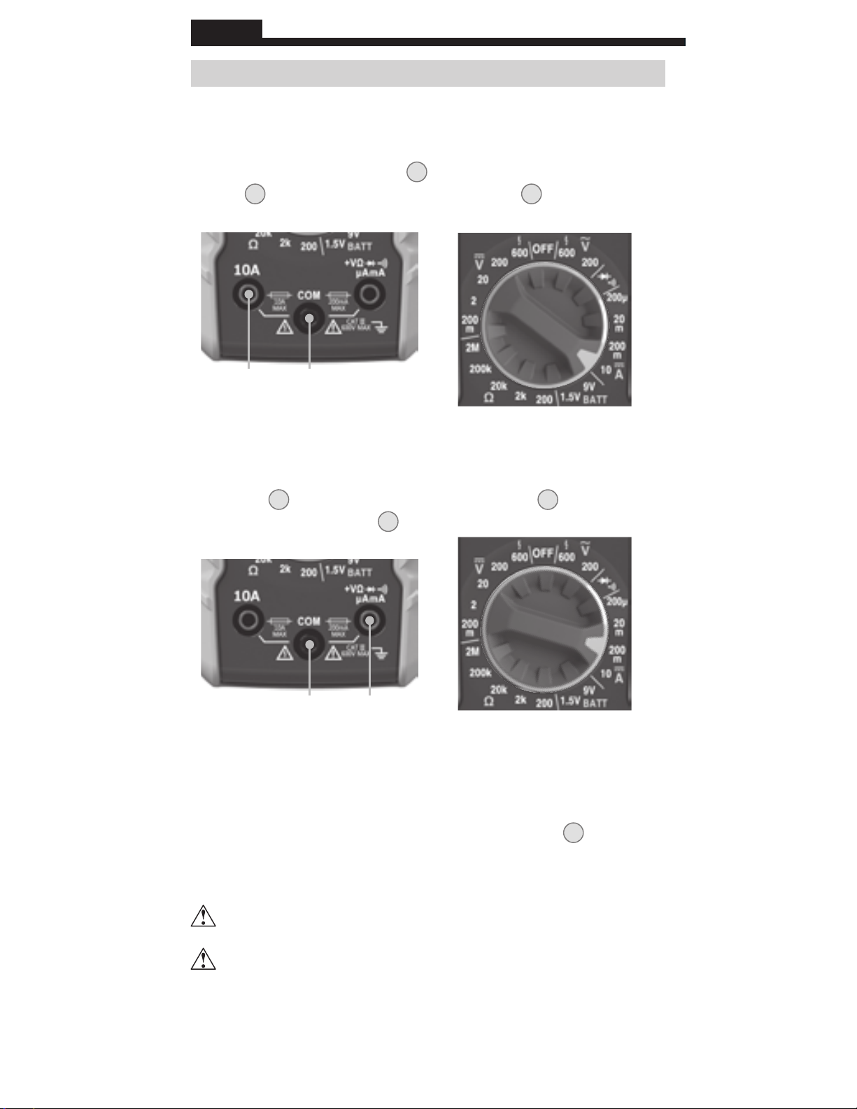
DC CURRENT 200mA to 10A
1. For DC currents more than 200mA and less than 10A, insert
RED test lead into 10A jack
jack
, and rotate function selector switch 2 to the
4
, and BLACK test lead into COM
3
10A DC setting.
Red lead Black lead
DC CURRENT LESS THAN 200mA
2. For mA DC currents less than 200mA, insert RED test lead into
VΩ jack
function selector switch
, and BLACK test lead into COM jack 4, and rotate
5
to the highest mA DC setting (200mA).
2
Red leadBlack lead
3. To measure current: Remove power from circuit, open circuit at
measurement point, connect meter in-series in the circuit using
the test leads, and apply power to cir
cuit.The meter will auto-
range to display the measurement in the most appropriate range.
NOTE: If measuring mA, the function selector switch 2 may be
rotated to successively lower mA DC settings to obtain higher
resolution measurements.
Do not attempt to measure more than 10A.
When measuring currents greater than 6A, a measurement
time of 30 seconds followed by 10 minutes of recovery time
is recommended.
Find Quality Products Online at: [email protected]
8
www.GlobalTestSupply.com
Page 9
OPERATING INSTRUCTIONS
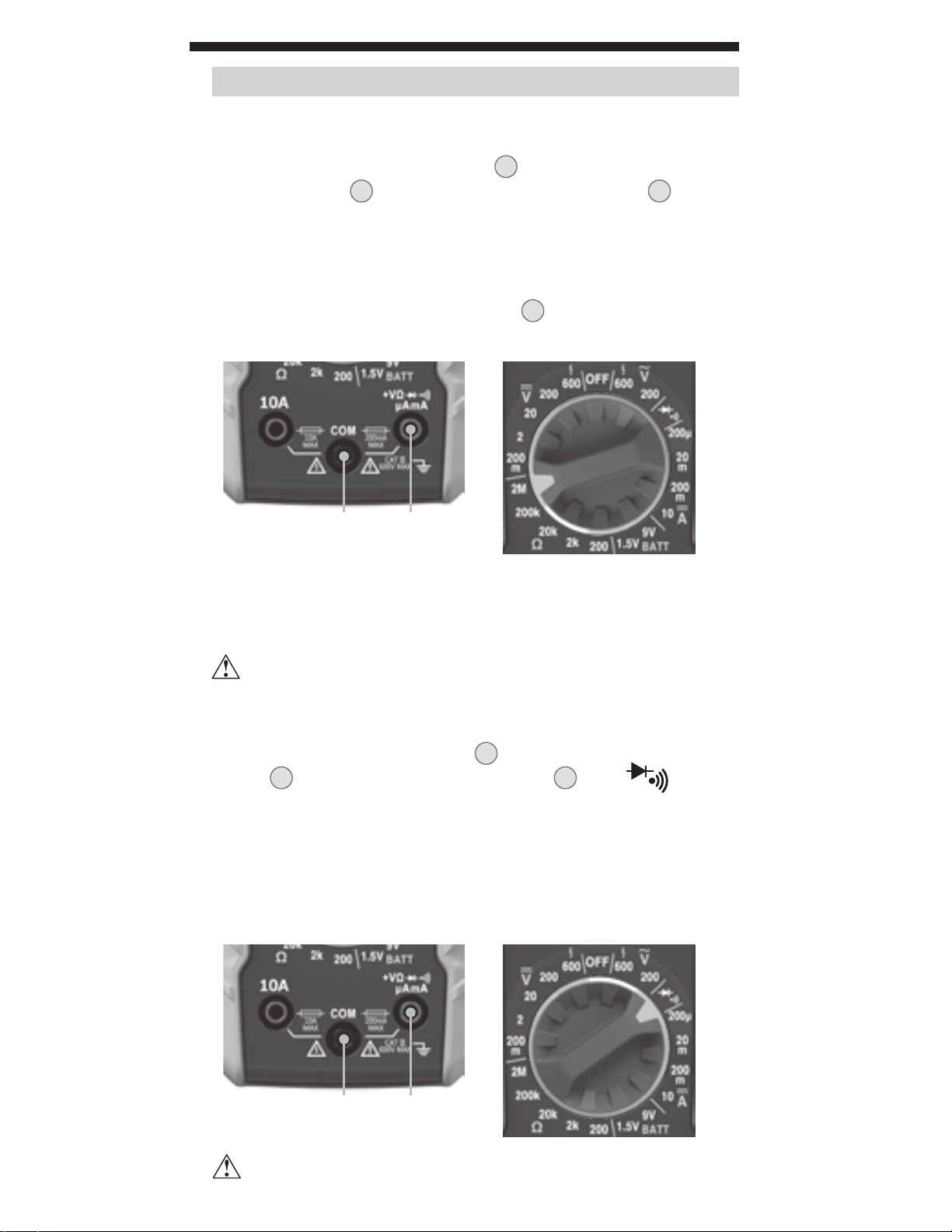
RESISTANCE MEASUREMENTS
1. Insert RED test lead into VΩ jack
into COM jack
,
and rotate function selector switch 2 to the
4
, and BLACK test lead
5
highest Ω setting (2MΩ).
2. Remove power from circuit.
3. Measure resistance by connecting test leads to circuit and
rotating the function selector switch
to successively
2
lower Ω settings to obtain higher resolution measurements.
Red leadBlack lead
NOTE: When in a Resistance setting and the test leads are open
(not connected across a resistor), or when a failed resistor is under
test, the display will indicate O.L. This is normal.
DO NOT attempt to measure resistance on a live circuit.
CONTINUITY
1. Insert RED test lead into VΩ jack 5 and BLACK test lead into COM
jack
, and rotate function selector switch 2 to the setting.
4
2. Remove power from circuit.
3. Test for continuity by connecting conductor or circuit with test
leads. If resistance is measured less than 100Ω, an audible
signal will sound and display will show a resistance value
indicating continuity. If circuit is open, display will show "OL".
Red leadBlack lead
DO NOT attempt to measure continuity on a live circuit.
Find Quality Products Online at: [email protected]
www.GlobalTestSupply.com
9
Page 10
ENGLISH
OPERATING INSTRUCTIONS
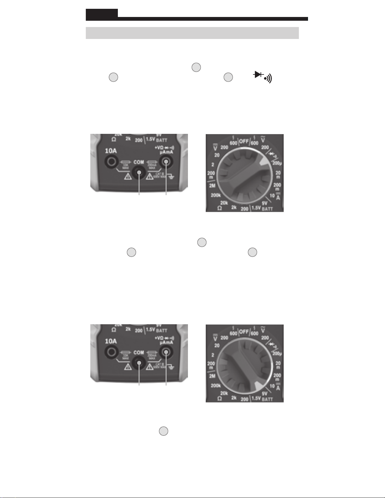
DIODE TEST
1. Insert RED test lead into VΩ jack 5 and BLACK test lead into COM
jack
, and rotate function selector switch 2 to the setting.
4
2. Touch test leads to diode. A reading of 200-700mV on display
indicates forward bias, OL indicates reverse bias. An open
device will show OL in both polarities. A shorted device will
show approximately 0mV
.
Red leadBlack lead
BATTERY TEST
1. Insert RED test lead into VΩ jack
COM jack
, and rotate function selector switch 2
4
and BLACK test lead into
5
to the 1.5V
or 9V battery test setting.
2. Connect BLACK lead to negative, and RED lead to positive
terminal of batter
3.
Measure voltage on display
y.
, batteries in good condition should
be within approx. 10% of rated voltage.
Red leadBlack lead
DATA HOLD
Press Data Hold button
t
o hold the measurement on the display.
6
Press again to release the display and return to live measuring.
Find Quality Products Online at: [email protected]
10
www.GlobalTestSupply.com
Page 11
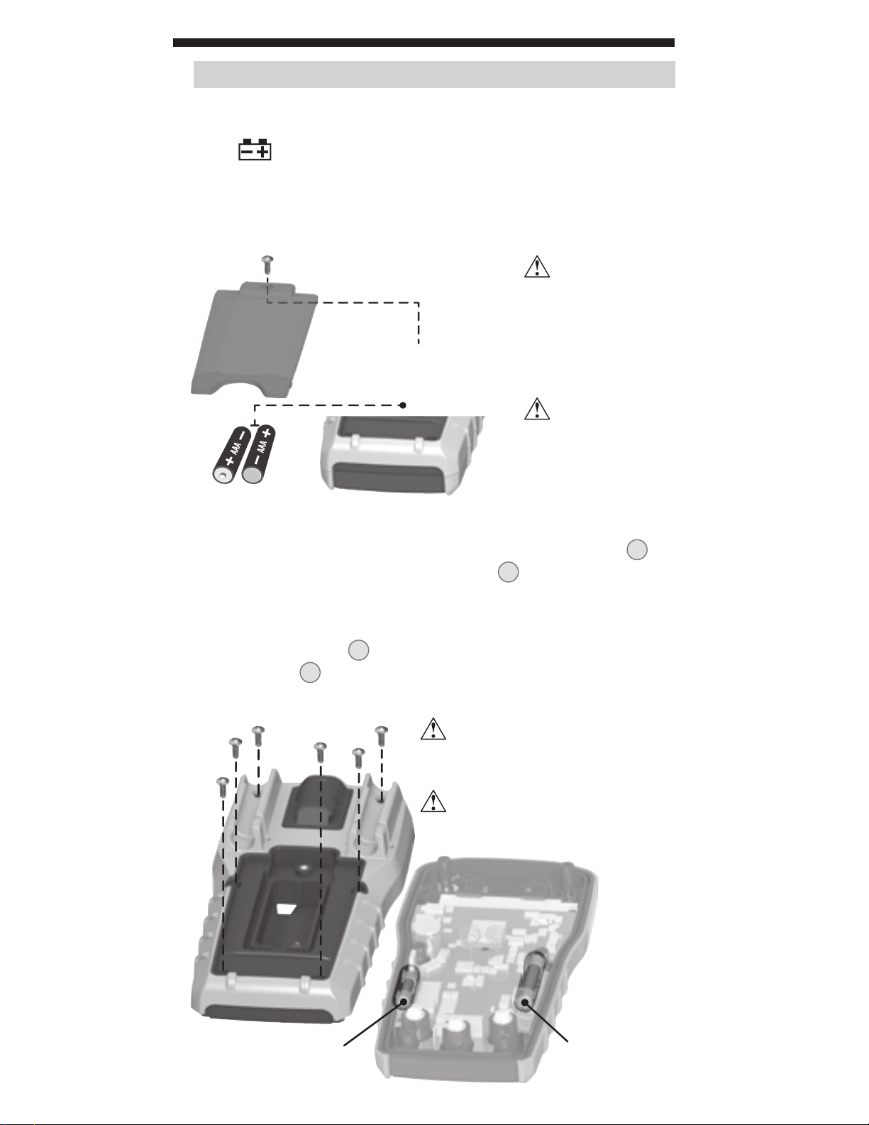
MAINTENANCE
BATTERY REPLACEMENT
When
Remove screw from battery door.
1.
2. Replace 2 x AAA batteries (note proper polarity).
3.
Replace battery door and fasten securely with screw.
indicator is displayed on LCD, batteries must be replaced.
T
o avoid risk
of electric shock,
disconnect leads from
any voltage source
before removing
battery door.
To avoid risk of
electric shock, do
not operate meter
while battery door
is removed.
FUSE REPLACEMENT
A fuse may blow if more than 200mA is applied to the
or more than 10A is applied to the 10A jack
. To access fuses:
3
VΩ
jack 5,
1. Remove 6 screws from back of meter and remove back housing.
2. Replace blown fuse(s) with:
VΩ (μA/mA) jack 5: 200mA/600V fast-blow (Klein Cat. No. 69031)
10A jack 3: 10A/600V fast-blow (Klein Cat. No. 69032)
3. Replace back housing and fasten securely with screws.
To avoid risk of electric shock,
disconnect leads from any voltage
source before accessing fuses.
To avoid risk of electric shock,
do not operate meter while back
housing is removed.
200mA/600V
fast-blow fuse
(Klein Cat. No. 69031)
Find Quality Products Online at: [email protected]
www.GlobalTestSupply.com
(Klein Cat. No. 69032)
10A/600V
fast-blow fuse
11
Page 12

ENGLISH
CLEANING
Be sure meter is turned off and wipe with a clean, dry lint-free
cloth.
Do not use abrasive cleaners or solvents.
STORAGE
Remove the batteries when meter is not in use for a prolonged
period of time. Do not expose to high temperatures or
humidity. After a period of storage in extreme conditions
exceeding the limits mentioned in the General Specifications
section, allow the meter to return to normal operating
conditions before using.
DISPOSAL / RECYCLE
Do not place equipment and its accessories in the trash.
Items must be properly disposed of in accordance with local
regulations. Please see www.epa.gov or www.erecycle.org
for additional information.
Find Quality Products Online at: [email protected]
www.GlobalTestSupply.com
 Loading...