

CONDUIT BENDER AND ANGLE SETTER™ GUIDE
Offset Bend Steps
1.
Measure distance X to obstruction and height Y to clear obstruction.
2. Multiply height Y by shrink/inch. Add this to distance to obstruction X.
This is first bend line.
Multiply height Y by constant multiplier. This is distance between bends.
3.
Mark second bend line at this distance.
4. Bend first bend using first bend line. Spin conduit 180° and perform
second bend using second bend line.
Saddle Bend Steps
Measure distance X to center of obstruction and height Y to
1.
clear obstruction.
Add distance X to center of obstruction to shrink value from Saddle
2.
Bend table. Make center bend mark at this distance.
Multiply height Y by constant multiplier. This is distance between bends.
3.
Mark second bend line at this distance.
4.
Bend first bend using first bend line. Spin conduit 180° and perform
second bend using second bend line.
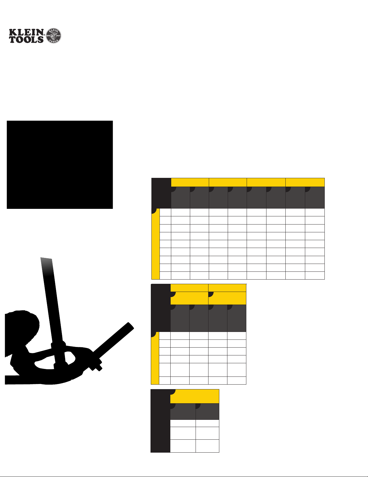
ZIP
GUIDETM
FOR
OFFSETS
A
2"
3"
4"
5"
6"
7"
Offset Depth
8"
9"
10"
ZIP
GUIDETM
FOR
SADDLES
A
1" 2-1/2" 3/16" 2" 1/4"
2" 5" 3/8" 4" 1/2"
3" 7-1/2" 9/16" 6" 3/4"
4" 10" 3/4" 8" 1"
5"
Obstruction Height
6" 15" 1-1/8" 12" 1-1/2"
22-1/2º 30º 45º 60º
CB
Distance
Between
5-1/4" 3/8" —
7-3/4" 9/16" 6" 3/4" — — — —
10-1/2" 3/4" 8" 1" — — — —
15-1/2" 1-1/8" 12" 1-1/2" 8-1/2" 2-1/4" 7-1/4" 3"
18-1/4" 1-5/16" 14" 1-3/4" 9-3/4" 2-5/8" 8-1/2" 3-1/2"
20-3/4" 1-1/2" 16" 2" 11-1/4" 3" 9-5/8" 4"
23-1/2" 1-3/4" 18" 2-1/4" 12-1/2" 3-3/8" 10-3/4" 4-1/2"
B B
Distance
Center
Amount
Bends
13" 15/16" 10" 1-1/4" 7" 1-7/8" — —
26" 1-7/8" 20" 2-1/2" 14" 3-3/4" 12" 5"
45º 60º
22.5º
Return Bends
DC
From
Amount
Mark
12-
15/16" 10" 1-1/4"
1/2"
Shrink
Shrink
Distance
Between
Bends
Return Bends
Distance
From
Center
Mark
CB CB CB
Distance
Shrink
Amount
30º
DC
Amount
Between
— — — — —
Shrink
Bends
Amount
Shrink
Distance
Between
Bends
Shrink
Amount
A
BENDER
TAKE UP
TABLE
1/2" Ridgid
3/4" Ridgid
KLEIN TOOLS, INC
© 2020
Find Quality Products Online at: sales@GlobalTestSupply.com
MKT200815 Rev. 09/20 A
www.GlobalTestSupply.com
90º
Stub-Up Bend
CB
Conduit
Size
1/2" EMT 5"
3/4" EMT
1" EMT
Stub
Height
6"
8"
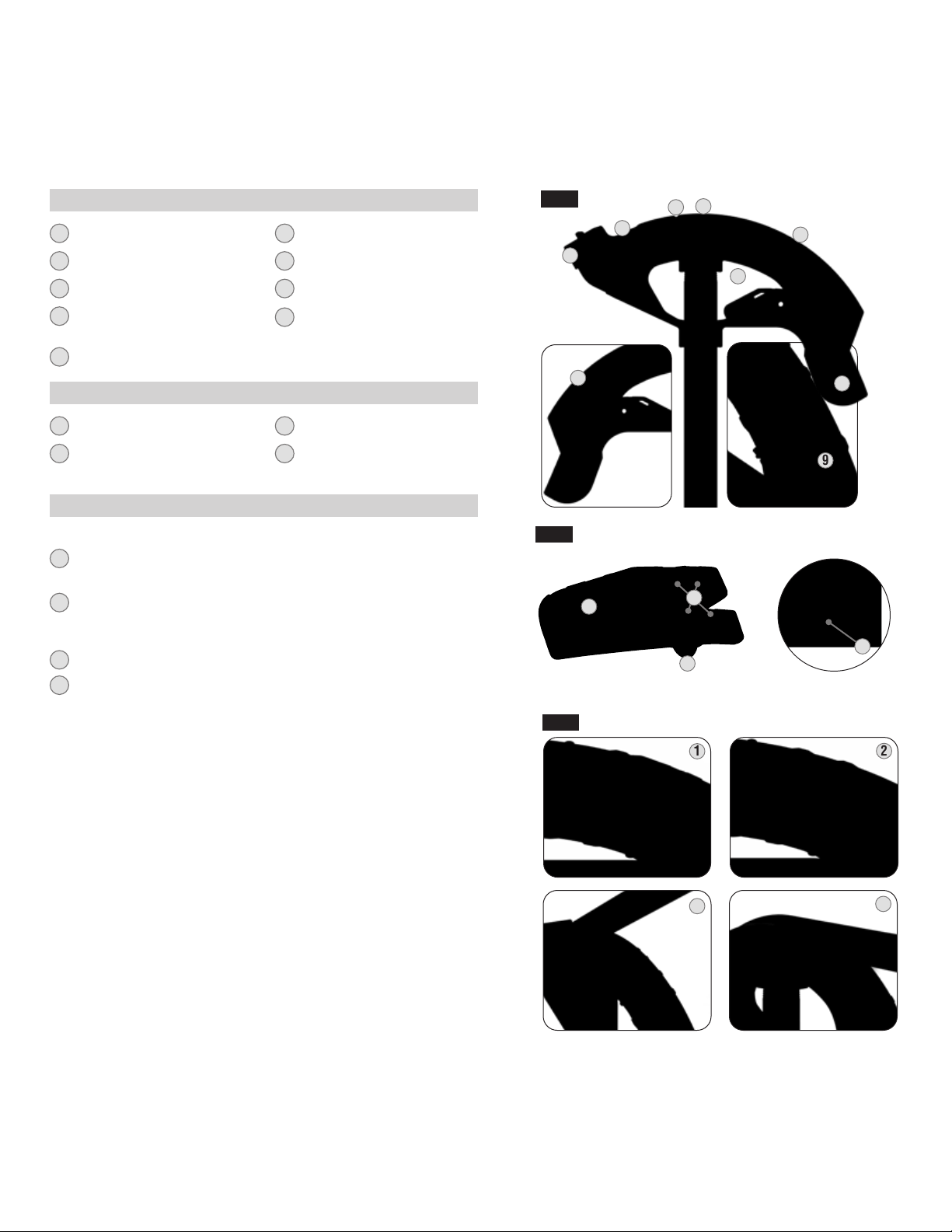
1
Hook
2
Alignment Arrow
3
45° Center-of-Bend
90° Back-of-Bend &
4
60° Center-of-Bend
5
Bend Angle Lines
CONDUIT BENDER — FIG. 1
6
Foot Pedal
7
Angle Setter™ Storage
8
Bend Angle Multipliers
Alignment Notches
9
(use with Angle Setter™)
ANGLE SETTER™* — FIG 2
FIG. 1
4
3
2
1
7
8
5
6
1
Conduit Stop Track
2
Angle Alignment Grooves
* For use with EMT Conduit
3
Alignment Tabs
4
Lanyard Hole
ANGLE SETTER™ INSTRUCTIONS — FIG 3
Use markings for desired bend angle (10°, 22.5°, 30°, 45°)
Align the Angle Setter™ alignment groove with end of bender head
1
angle line (30º shown).
Using your palm, press Angle Setter™ firmly into place, until
2
it is flush with the sides of the bender channel - ensure
alignment tabs are fully seated into alignment notches.
Insert conduit into bender head and prepare to bend as usual.
3
Bend conduit until contact with the Angle Setter™ is felt.
4
Will work for floor and air bends.
Caution: Bending past Angle Setter™ can result in kinks in conduit
FIG. 2
FIG.3
9
1
2
4
3
1
2
3
Find Quality Products Online at: sales@GlobalTestSupply.com
www.GlobalTestSupply.com
4
 Loading...