

Page 1

Monitor Management System
Operators Guide
Pre-Programmed Setups
Connection Diagram
Programming: Surround 5.1
K+H Vertriebs- und
Entwicklungsgesellschaft mbH
Auf dem Kessellande 4a • 30900 Wedemark/Germany
P
RO
M 1012
058-E0159
Version 060426
SW Rev KH 2.000
Tel: +49 (0) 5130 5848
-
0
Fax: +49 (0) 5130 5848-11
www.klein-hummel.com
www.klein-
hummel.com
Page 2
PRO M 1012 page 2 of 6
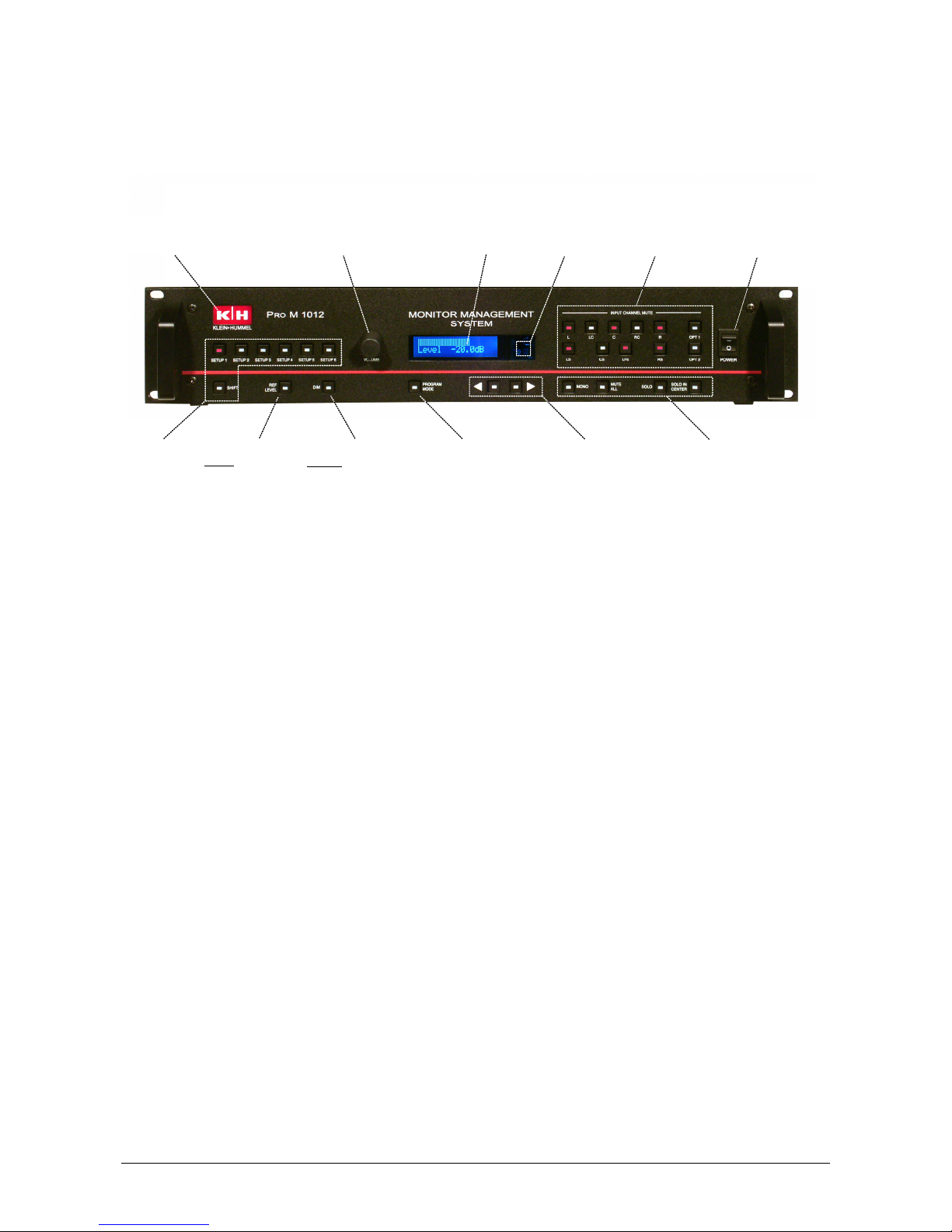
1 Operation Instructions
Sensor für IR-
Fernbedienung
Setup-Auswahl:
- 1...6
- via Shift: 7...12
LCD Display
Inkrementgeber:
- Volume im normalen Arbeitsmodus
- Parametervariation im Programmiermodus
- Enter-Taste im Programmiermodus (Push)
Logobeleuchtung =
Einschaltkontrolle
Setzen der Lautstärke
auf einen vordefinierten
Pegelwert
Absenken der
Lautstärke um einen
vordefinierten Pegelwert
Umschaltung zwischen
normalem Arbeitsmodus
und Programmierbetrieb
(Taste blinkt!)
Kanalwahltasten für
Eingangskanäle Netzschalter
Betriebsart der
Kanalwahltasten
Left/Right - Pfeiltasten
für Parameteranwahl im
Programmierbetrieb
The PRO M 1012 has 80 Basic Configurations stored in internal memory. Twelve of these may be
quickly recalled as preprogrammed setups. Basic Configurations define all signal routing and gain
settings plus all parameter values configured in Program Mode for the input and output channels
(see Pro M 1012 Reference Manual)
• Setups 1 - 6 can be recalled by pressing the numbered SETUP keys and setups 7 - 12 by
pressing the SHIFT + SETUP keys. When a SETUP is recalled, the LCD briefly shows the
SETUP No. and name and then displays the current volume level on the bottom line.
• VOLUME Control (rotary encoder) for adjusting the volume level or for changing parameter
values in Program Mode. When the volume level is adjusted, the top line of the LCD display
shows a volume-level bar graph.
• REF LEVEL key recalls the reference volume level and the DIM key decreases the volume
level (Default values: REF = 0 dB, DIM = -20 dB).
• INPUT CHANNEL MUTE keys mute individual or multiple input channels (channel key is
illuminated when muted)
• SOLO key activates (solo-in-place) the selected input channels (SOLO key is illuminated
and INPUT CHANNEL key flashes)
• SOLO IN CENTER key will solo the selected input channels and route them to the center
channel output (SOLO key and SOLO IN PLACE key are illuminated and the INPUT
CHANNEL key flashes)
• PROGRAM MODE key activates the Program Mode to change or store setups, select new
Basic Configurations, trim gain levels, etc.
Logo Illumination
= Power On
Incremental Encoder:
- Adjusts Volume in normal Operation Mode
- Variation of Parameters in Programming Mode
- Enter-Key (Push) in Programming Mode
IR Remote
Control Sensor
Input Cannel
Selection Keys
Mains Power
Switch
SETUP Keys: 1 – 6
SHIFT Key: 7 - 12
REF LEVEL key
Recalls reprogrammed
Volume level
DIM key
Reduces Volume to
preprogrammed level
PROGRAM MODE key
Switches between normal
Operation Mode and
Programming Mode (Key
Fl
ashes!)
Left / Right Arrow Keys
to Select Parameters in
Programming Mode
Operating Mode for
Input Channel Keys
Page 3

PRO M 1012 page 3 of 6
2 Pre-Programmed Setups 1 - 12
SETUP 1
SETUP 2
SETUP 3
SETUP 4
SETUP 5
SETUP 6
9-5.1-Su/SW
5.1 Surround,
Bass Management
(LFE+LF routed to
Sub output)
13-5.1-Su/LCR
5.1 Surround,
LFE routed to
L/C/R outputs
25->2/0-SuLR/SW
Downmix 5.1 to
2/0, reproduced by
L/R+Sub outputs
24->1/0-SuC/SW
Downmix 5.1 to
1/0, reproduced by
C+Sub outputs
46-ST1-SuLR/SW
Stereo Input 1,
reproduced by
L/R+Sub outputs
7-ST2-SuLR/SW
Stereo Input 2,
reproduced by
L/R+Sub outputs
Shift +
SETUP 1
Shift +
SETUP 2
Shift +
SETUP 3
Shift +
SETUP 4
Shift +
SETUP 5
Shift +
SETUP 6
16-5.1-Su/DIS
5.1 Surround,
LFE routed to
dedicated Sub
output
79--- MUTE --
(free)
29->2/0-LR2
Downmix 5.1 to
2/0, reproduced
by L/R(2) outputs
28->1/0-LR2
Downmix 5.1 to
1/0, reproduced
by L/R(2) outputs
42-ST1-LR2
Stereo Input 1,
reproduced by
L/R(2) outputs
3-ST2-LR2
Stereo Input 2,
reproduced by
L/R(2) outputs
3 Basic Configurations
• A Basic Configuration defines all signal routing and gain settings plus all parameter values
for the input and output channels
• The PRO M 1012 has 80 Basic Configurations stored in internal memory. Twelve of these
may be quickly recalled as preprogrammed Setups by pressing the numbered SETUP keys
(or SHIFT + SETUP). The factory preprogrammed setups are shown in the table above.
• The 80 Basic Configurations plus all additional settings saved in Program Mode define the
PRO M 1012’s Project File (*.prj)
• Project Files can be changed or created with the PRO M 1012 Configuration Manager
Software using a PC (running Windows® version 98 or later), after first transferring the file
to the PC (see Configuration Manager Manual)
3.1 Recalling Basic Configurations and Storing them as Setups:
• Press “PROGRAM MODE” key (will start flashing to indicate initiation of Program
Mode)
• Go to „BASIC CONFIGURATION“ menu by turning the incremental encoder, then
press the incremental encoder to verify
• Name and number of Basic Configuration will be shown in the second line of LCD
display. (Format: [BasicConfigNo]-[BasicConfigName])
• Turn the incremental encoder to select desired Basic Configuration, then press to
activate it
Page 4

PRO M 1012 page 4 of 6
• To store this temporary Basic Configuration as a base of one of setups 1…12, turn
incremental encoder one step back to “STORE SETUP” menu and verify by
pressing it
• Select desired setup (1...12) by turning the incremental encoder, then press to store
it
• Press “PROGRAM MODE” key (will stop flashing, system works in normal operation
mode again)
Page 5

PRO M 1012 page 5 of 6
4 Rear Panel Connection Diagram
8 Ch Option Board
L C R LS RS
R 2 L 2 R 1
L1
L 1
R1 ---
SUB1
LFE RS LS
SUB2
R
L2
C
R2
L
1234567
8
---
---
---
---
---
---
---
---
2-
ChMaste
r
SubgroupsInput Section
(...)
CDCD
Stereo
Source 1
Stereo
Source 2
Wide
Source
-
-
-
-
-
-
N
o
t
i
n
s
t
a
l
l
e
d
-
-
-
-
-
-
R
LS
RS
L
C
R
L
(ST2) (ST1)
(5.1)
Near-
field
Sur LR(2)
WRC 1012 RS-232
Sub
Project-File: Pro M 1012 Surround 5.1_GUI2.004_111005 .prj
Page 6

PRO M 1012 page 6 of 6
Appendix
A1 Transferring New Project Files from a PC to the PRO M 1012
Important note! The Pro M 1012’s Project File contains the 80 Basic Configurations plus all user-
defined parameter settings. If the existing parameter settings need to be saved for future use, then
transfer the existing Project File to the Configuration Manager (see A2) before transferring a new
project file to the PRO M 1012!
• Connect the 9-Pin D-SUB RS-232 connector on the rear panel of the PRO M 1012 to the
PC
• Double-click the ProM1012ConfigMan.exe file to start installation of the PRO M 1012
Configuration Manager and follow the instructions given during the installation process.
(File is included on the CD-ROM that is supplied with the Pro M 1012 or may be
downloaded from www.klein-hummel.com)
• After successful installation, start Configuration Manager and apply power to the PRO M
1012
• In File => Open Project, open the new Project File
• In Transmit/Receive => Connection, set the correct COM Port (typically COM2, however,
when using USB-to-RS-232 adapter cables the correct Port can be checked in the
Hardware menu of the Windows® Control Panel)
• In Transmit/Receive => Transmit to Pro M 1012, select Transmit whole Project
• Check OK to start the transfer process. Progress will be indicated by the blue bar
• The message “Project has been transmitted successfully!“ will appear, when the transfer is
complete
A2 Transferring the System’s Project File to a PC
• Start Configuration Manager and apply power to the PRO M 1012
• In Transmit/Receive, select Receive from Pro M 1012 => Receive whole Project
• Check OK to start the transfer process. Progress will be indicated by the blue bar
• The message “Project has been transmitted successfully!“ will appear, when the transfer is
complete
• The Project File can now be opened in Configuration Manager and can be edited and
stored via File => Save Project as...
 Loading...