

Page 1

Stereo High-Power Amplifier
Installation
and
Operation
PRO A 2000
KLEIN + HUMMEL GmbH
Zeppelinstr. 12 73760 Ostfildern/Germany
Tel.: + 49 - (0)711 - 45893 - 0
Fax: + 49 - (0)711 - 45893 - 35
e-Mail:info@klein-hummel.de
Internet:www.klein-hummel.de
058-E0021
Version 01-20-2004
Page 2
Page 2 High Power Amplifier PRO A 2000
Safety Instructions
It is absolutely essential that you read these safety instructions carefully before connecting and using this K+H
product. Your safety depends on it. Furthermore, failure to follow these instructions voids the warranty. To ensure
safe operation for years to come, keep these instructions in a safe place for future reference. K+H has manufactured
this product in accordance with IEC 1992 (SEC) 39 standards, then tested and delivered it in safe operating condition.
To maintain it in this condition, you must:
• observe all safety instructions,
• use the product only as described herein,
• have any maintenance, repairs, or modifications performed only by K+H or other authorized personnel, and
• ensure that the room in which you use this product is wired in accordance with the local electrical code.
Warning!
• When the interior of the cabinet is exposed, touching some parts can lead to an electric shock.
• If you need to gain access to the interior electronics of the unit, always disconnect the unit from any and all power
sources first.
• Any repairs, maintenance, or other service of the unit when its interior compartment is exposed may only be
performed safely (in accordance with VBG 4) by authorized technicians familiar with all the risks
involved. Even in an unplugged state, a fully charged capacitor in the unit can zap the
unsuspecting.
• Loudspeaker output jacks labeled with the IEC 417/5036 emblem (Fig. A, right) may be carrying
dangerously high voltages. If your unit has this emblem, ensure that any connections to be
made between these jacks and the speakers themselves are made before powering up the
unit, and are done so only with manufacturer-approved interconnecting cables.
• If you need to replace any fuses, ensure that the replacements are of exactly the same type,
value and voltage as the originals, as spelled out in the technical specifications at the rear of
this manual.
• Do not use "repaired" fuses.
• If you do not have any fuses on hand of the specified size, type, and value, do not hot-wire the
contacts in the holder by short-circuiting them.
• Certain areas of the cabinet, cover, and rear panel can achieve extreme temperatures and are
therefore marked with a "HOT" label (Fig. B). Refrain from touching any heat sink or ventilation
grille.
• High volume levels are known to cause permanent - i.e. irreversible - hearing damage, especially
when listened to without sufficient breaks. The higher the levels, the more frequent and extended must be the breaks. Avoid standing too close to loudspeakers that are being driven at high
levels. If you must be exposed to high sound pressure levels over an extended period of time,
use hearing protection.
Mains Connection:
• This unit is designed for continuous operation.
• Ensure that the operating voltage of the unit matches that of the local mains current (AC line voltage).
• Always check before connecting the power cable to the mains socket that the power switch on the unit itself is set
to off ("O").
• Use the power cable or power supply that came with the unit to connect to the mains socket (wall outlet).
• Power supply: a damaged power cable may not be repaired. Use a new cable.
• Avoid plugging the mains cable into a power strip that already has several other power-consuming devices
connected to it.
• Avoid using extension cables. The unit must be connected to a mains socket close to it, and that socket should
be freely accessible.
Installation:
• This product may only be placed on a stable, clean, horizontal surface.
• Do not expose this product to vibration.
• Do not operate this product anywhere near water or other liquids. Do not use it near a sink, swimming pool,
bathtub, or in any damp room or area. Electrical shocks carried through water can kill. Do not place any beverages
whatsoever on or near this product, as liquids can kill electronic components.
• Ensure sufficient ventilation around the product to allow for adequate heat dissipation, especially near the rear
panel and the sides of the cabinet (minimum of 8 inches from the nearest wall). The unit may only be installed in
a rack if measures are taken to ensure sufficient ventilation and if the mounting instructions of the manufacturer
are followed. Do not block or cover any heat sink, fan, or vent.
• Do not place the product where it will be in the path of direct sunlight, and keep it a safe distance away from
radiators and other heaters of any kind.
• If you bring this product from a cold environment into a warm one (such as from a vehicle into a studio), it is quite
possible that condensation will form inside the cabinet. Please allow the unit sufficient time for acclimatisation
to room temperature (minimum thirty minutes) before connecting and powering up.
• To avoid accidents, do not use any accessory equipment with this product which is not approved by the manufacturer,
particularly mounting accessories. Do not place this unit on any unstable platform, cart, stand or table. Should the
unit fall, it can cause bodily injury to persons, or can be damaged itself.
• To protect this product from lightning damage during a thunderstorm or from power surges during an extended
absence, disconnect the power cable from the wall outlet.
Fig. A
Fig. B
Page 3
High Power Amplifier PRO A 2000 Page 3
High Power Amplifier PRO A 2000
Precision Audio Line
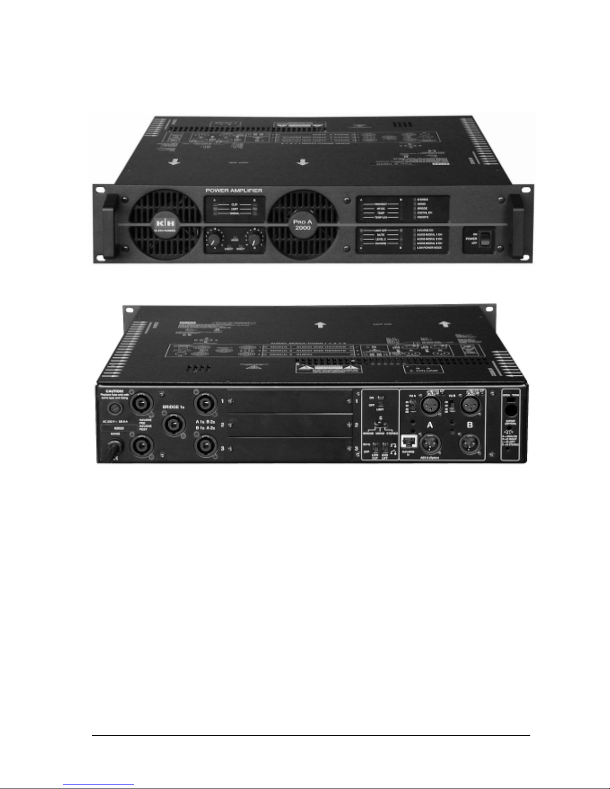
Fig. 1 Front view
Fig. 2 Rear view
Table of Contents:
Safety Instructions...............................................2
Illustrations, table of contents ..............................3
1. Basic Information .............................................4
2. Installation........................................................4
2.1 Read this first. ............................................ 4
2.2 Operating conditions ................................... 4
2.3 Rack Installation ......................................... 4
2.4 Cooling........................................................ 4
2.5 Mains connection........................................ 4
2.6 Mains switch (POWER)............................... 4
2.7 Mains fuse .................................................. 5
2.8 Output Power .............................................. 5
2.9 Connecting to audio-sources ....................... 5
2.10 Output connectors..................................... 5
2.11 Expansion module slots ............................ 6
2.11.1 Controls and jumpers in the slots ....... 6
3. Operation .........................................................6
3.1 Front panel .................................................. 6
3.2 Indicators and level control ......................... 6
3.3 Diagnosis indicators.................................... 6
3.4 Determining modes and signal inputs .......... 7
3.5 Digital Audio input (optional)........................ 8
3.6 Protection circuit and limiter functions......... 8
3.6.1 Overcurrent limiter................................ 8
3.6.2 Temperature rise limiter ........................ 8
3.6.3 RMS limiter .......................................... 8
3.6.4 Distortion limiter................................... 8
3.6.5 Peak limiter .......................................... 8
3.6.6 Dynamic overcurrent limiter.................. 8
3.6.7 High frequency and DC protection ........ 8
3.6.8 Temperature protect.............................. 9
4. In case of a problem.........................................9
5. Technical specification......................................10
Page 4

Page 4 High Power Amplifier PRO A 2000
1. Basic Information
The K+H PRO A 2000 is a highest performance
class AB high power amplifier. Most sophisticated
protection functions and high power reserves make
this amplifier the first choice for all applications.
Special features are: built in versatile limiter, which
can be disabled in part, 3 slots for expansion modules
such as controller for switching over to a redundant
power amplifier in case of failure (HAVARIE), remote
control, remote diagnosis, audio controller, parametric
2-band EQ, add on digital audio input interface and
high performance balancing input transformers. 100/
70 V output transformers are available as separate
units.
Basicly the P
RO A 2000 is designed for 4 Ohms load
impedance under hard conditions too, but dependant
on environmental effects and audio material, it can
drive loads down to 1.8 Ohms without loss in
performance. Safe operation of the amplifier itsself
and the connected speakers under all conditions and
faults is secured by costly protection circuits. Before
switching off the amplifier or the speakers, these
circuits try to go back to a safe operation condition in
reducing the output power by means of the thermal
and current limiters. This is very smoothly done and
without increasing THD. Not before these steps will
not do there will be a switch off. If any high frequency
(e. g. feedback to preamplifier) or DC-signals are
detected at the power output, the protection circuit
switches off both amplifier and speaker outputs
immediately.
2. Installation
2.1 It is absolutely essential that you read
and observe the Safety Instructions on
page 2 before connecting or using this
device.
2.2 Operating conditions
The K+H model PRO A 2000 high power amplifier is
intended for use over a range of ambient temperatures
from +10° C to +40° C (+50° F to +104° F). During
transport or storage, temperatures from -25° C to +70°
C (-13° F to 158° F) are permissible.
2.3 Rack Installation
When installing the PRO A 2000 to a rack it is
recommended to use sidewise bearings. In any case
the rear fastening angles have to be fixed to the rack
too.
Warning!
Because of the heavy weight the front
panel alone cannot carry the P
RO A 2000!
Please take care of sufficient ventilation
at both sides of the amplifier see figure 3:
Fig. 3 PRO A 2000 airflow
2.4 Cooling
The PRO A 2000 is equipped with a most efficient pushpull cooling system, which allows for sustained
continous operation at a 4 Ohms load. So the PRO A
2000 can be operated under hard conditions without
any air conditioning. Of course the ventilation in the
rack has to be sufficient.
The cooling air is drawn in at both sides and the cover
plates on top and bottom of the cabinet. For even
better cooling you can leave one unit above and one
under the amplifier blank.
The outlet air is blown out on the front panel.
2.5 MAINS Connection
The amplifier electronics of the standard European
model are set up for an AC line voltage of 230 volts,
50 or 60 Hz. Export versions with other voltages are
also available. If the power plug of the mains cable
should ever need to be replaced, ensure that the
connection to the protective earth is maintained.
2.6 MAINS Switch (POWER)
The mains switch is a 3-positon
rocker type. Shortly pushing the
upper end (ON) will power up the
PRO A 2000. After a 5 second on
delay it will be ready and the mains
LED will light up. Pushing the lower
end (OFF) will interrupt mains
power. If a remote control module is present and set
in function, all amplifiers in a set can be powered on
!
Fig. 4 Mains switch
Page 5

High Power Amplifier PRO A 2000 Page 5
and off with the mains switch of the first one. To avoid
excessive on currents the units are powered on one
after the other with a 3 second delay each.
Caution: Do not push the rocket switch
for a too long time if there are remote
control modules present in the system.
Some components inside the amplifier
could overheat!
2.7 Mains FUSE
When replacing the fuse, first disconnect the mains
cable and ensure that the new fuse is of the following
type only:
for 230 volts AC 16 A Slo-Blo (6.3 x 32 mm)
2.8 Output Power
The PRO A 2000 is stable without any restrictions as
to thermal and load specifications at a load impedance
of 4 Ohms and at any program material. The power
stage is able to generate a temporal limited RMS output
power of 650 watts and up to 850 watts peak power.
The ambient temperature should not exceed 40° C
(104° F).
At a 2.6 Ohms (= 3 x 8 ohms in parallel) load the PRO
A 2000 can provide temporarily 850 watts of sine and
1050 watts of peak power. Stability is warranted in
respect to the impedance but not always to the thermal aspects. Do not apply too compressed program
material and pay attention to the ambient temperature.
At 2 Ohms load impedance the PRO A 2000 will be
capable to deliver 1000 watts of sine power and 1200
watts of peak power. In some cases the protection
circuit will reduce output power due to excessive
temperature or load current. Do not compress the
audio signal and pay more and more attention to the
ambient temperature.
Caution: The PRO A 2000 is able to easily
destroy speaker systems! For safe
operation please be sure to apply only the
permissible power to each driver. The
limiter inside the amplifier has to be
adjusted suitable to speaker power
capability or use a special audio contoller.
2.9 Connecting to audio-sources
Use only screened professional audio cable to connect
the amplifier to your mixer or preamp. The balanced
input XLR connectors are wired in the standard manner:
Pin 1 = GND
Pin 2 = + (hot)
Pin 3 = - (cold)
Fig. 5 XLR connector wiring
2.10 Output connectors
Fig. 6 Speakon outputs
Havarie Pre insertion of HAVARIE post signal of the
preceding amplifier (if present), 4 wires!
(optional)
Havarie Post insertion of HAVARIE pre signal of the
following amplifier (if present), 4 wires!
(optional)
Bridge 1± speaker connector for bridge mode
A 1±, B 2± speaker A connector for mono or stereo
mode, also connector for K+H active top
speakers
B 1±, A 2± speaker B connector for mono or stereo
mode, also connector for non K+H active
top
Caution: Avoid shortcuts between ground
and the 1+ or 2+ termninals respectively
1+ and 1- as well as 2+ and 2-. It is true,
the PRO A 2000 is absolutely shortcut
proof, but shorting the outputs will
strongly heat up the power stage.
Page 6

Page 6 High Power Amplifier PRO A 2000
2.11 Expansion module slots
Fig. 7 Module slots
Module 1 slot for the first audio module in a chain
of 3, also for the optional HAVARIE card
Module 2 slot for the second audio module in a
chain of 3, also for the optional remote
control card
Module 3 slot for the third audio module in a chain
of 3
Caution: Make sure to have the amplifier
switched off before installing or removing
modules. Only the K+H PRO A 2000
modules may be inserted in the proper
slots. If you plug in non K+H products you
can destroy both modules and amplifier!
In this case product warranty will not be
extended!
2.11.1 Controls and jumpers in the slots
On the bottom of the slots you will find trim-pots
for adjusting the maximum permissable RMSpower, which the limiter allows for. It can be tuned
from 20 watts to maximum. By means of the
jumpers two limiter time constants can be selected:
a short one for high frequency drivers and a long
one for midrange and subwoofers.
Caution: When leaving the factory the
amplifier is set to maximum output power
and long time constant. Changing these
settings makes only sense, if the amplifier
is always used together with the same
speaker system. Only skilled personnel
with professional test equipment can
modify these settings. Inexpert altering
results in bad performance.
3. Operation
3.1 Front panel
The whole heated air of the power stage is blown out
over the front panel. Do not close the front side of the
amplifier rack for not to constrain the cooling otherwise
maximum power output cannot be guaranteed.
Module 1 Audio and HAVARIE
Module 2 Audio and Remote
Module 3 Audio
3.2 Indicators and level control
Fig. 8 Indicators and level controls
Signal A/B input level is - 20 dBu or more
Limit A/B peak-, RMS- or distortion limiter is active
Clip A/B input signal level is too high or amplifier
in the LIMIT OFF mode is overdriven
Mains amplifier is ready
A/B Direkt the front level controls are not functional.
This can be activated by the HAVARIE
module.
The trim-pots 2nd Volume on
the top-side can only be set in
function by the optional remote
control card.
Fig. 9 Trim-pots 2nd Volume
3.3 Diagnosis indicators
Fig. 10 Diagnosis indicators
Page 7

High Power Amplifier PRO A 2000 Page 7
Protect A/B a protection function is active, A/B-
speaker outputs are switched off, the
input of the power-stage is muted (Mute)
HF-DC A/B At the amplifiers output a non audible
signal such as HF or DC is present,
speaker outputs are switched off and the
power stage is muted (Protect and Mute)
Temp A/B the power stage A/B is overheated
(>90°C [>194°F])
Temp-Limit A/B
the temperature in the power electronics
has come up to 85°C (185°F), the limiter
reduces the output level by 10 dB
Limit off A/B
the internal distortion-, RMS- and peaklimiters are disabled when using an
audio-controller, the thermal limiter is
always active
Mute A/B channel A/B is muted
Level 2 A/B the intern 2nd volume trim-pots on top
are enabled, the front side volume
controls are out of order
Havarie A/B one or both channels are defective,
inputs and outputs are switched over to
a redundant amplifier. This function is
only available with the optional HAVARIE-unit.
Stereo normal stereo operation
Mono mono operation, both channels are fed
by the A-input signal
Bridge the two channels are working in bridge
mode and are fed via the A-input
connector. Please use only the bridge
marked speakon output connector - see
figure 5.
Digital on the optional analog to digital converter
is in operation. Only the digital inputs
(AES/EBU and SPDIF) are active.
Remote an optional remote control card has been
plugged in and is active
Havarie on an optional HAVARIE-card has been
plugged in and switched on
Audio-Modul 1 on
an optional audio-module has been
activated in slot 1
Audio-Modul 2 on
an optional audio-module has been
activated in slot 2
Audio-Modul 3 on
an optional audio-module has been
activated in slot 3
Low Power Mode
the power stage is in standby mode,
because there is no input signal present.
In the automatic standby-mode the
power stages idle current is put to zero
to reduce energy consumption and not
to heat up the rack needlessly.
3.4 Determining modes and signal inputs
Fig. 11 Inputs and mode switches
Limit on/off deactivates all limiters except for the
thermal limiter, which is always in
function. Plugged in modules can
possibly disable this setting.
Stereo/Mono/Bridge
slide switch to control the operating
mode:
stereo via the A and B-inputs,
mono and bridge mode via the A-channel
input connector only. Upside the switch
you will find a LED, which indicates the
switch is operating. Possibly inserted
modules can disable this switch too. If
so the LED will extinguish.
Low cut in the 30Hz position the switch activates
a subsonic filter with a cut-off frequency
of 30 Hz and a 12 dB/octave slope.
Ground lift slide switch for separating signal ground
from chassis ground. In any case the
chassis ground remains connected to
the protective earth (PE) connector of
the power cord.
Warning!
The protective earth conductor must
never be interrupted even for test
purposes! This may be dangerous to life!
Havarie in
When using the amplifier
as a redundant unit to
replace a defectice
amplifier in a HAVARIE
system, the input signal
coming from the HAVARIE cards of the faulty
amplifier(s) will be send
to this western
connector. You can use
the western input
instead of the XLRinputs too.
!
Fig. 12 Havarie in
connector
Page 8

Page 8 High Power Amplifier PRO A 2000
VU A, VU B select total gain:
26, 32 or 36 dB.
A (AES3) input channel A when in stereo mode or
input when in mono and bridge mode or
input for AES/EBU digital audio when
using the optional digital to analog
converter module
B input channel B when in stereo mode. In
mono or bridge mode the B-inputs are
not functional.
CP clip-LED indicates input A/B overload
SG signal-LED will light as the input signal
exceeds - 20 dBu
3.5 Digital Audio Input (optional)
When present the digital audio interface
is located at the utmost right side on
the back of your PRO A 2000 amplifier.
S/PDIF
BNC-connector 75 Ohms to feed the digital interface. Via the XLR channel A
input a AES/EBU digital audio source
can be connected too.
A/R/L/S
rotorary switch for selecting analog or
digital operation and for establishing how
the amplifiers inputs are assigned to the
left and right channels within a digital
stereo signal:
Fig. 13
Digital interface
A Analog
the digital interface is switched off. The
PRO A 2000 behaves as if the interface
would not exist.
R Digital right
the interfaces right output is sent to the
amplifiers A-channel (mono and bridge
mode). That is why the B-channel is not
connected.
L Digital left
the interfaces left output is sent to the
amplifiers A-channel (mono and bridge
mode). That is why the B-channel is not
connected too.
S Digital stereo
the interfaces stereo output is sent to
the amplifiers A- and B-channels for normal stereo operation.
Open/Term(inated)
switch for internal terminating resistor
Term input is terminated. The input has to be
terminated when the interface is the only
one connected to a digital source or if it
is the very last one in a chain of several
amplifiers.
Open input is not terminated. The input may
not be terminated, if several amplifiers
are connected in a chain to one digital
audio source by means of BNC Tconnectors. However the coaxial cable
has to be terminated at both the very
ends, so the last amplifier in such a
chain has to terminate it.
3.6 Protection circuit and limiter functions
3.6.1 Overcurrent limiter
This limiter takes effect as the total speaker
impedance is lower than 1.8 Ohms. If the current
rises up too high, the audio level is reduced in
such a way, that no overcurrent can occur. At the
limit off position of the limiter switch (see
figure 11) this function is disabled.
3.6.2 Temperature rise limiter
If the heat sinks temperature inside the PRO A 2000
rises up to 85°C (185°F) and more this thermal
limiter reduces the audio level very smoothly by
10 dB to counteract an excessive rise in
temperature. The temperature rise protection circuit
is always in function.
3.6.3 RMS limiter
Designates the maximum RMS - power as adjusted
with the trim-pots in the expansion module slots see chapter 2.11.1. When setting the LIMIT-switch
(figure 11) to the OFF position, the RMS limiting
function is disabled.
3.6.4 Distortion limiter
This limiter function counteracts every kind of
distortion by reducing smoothly the operating level.
When setting the LIMIT-switch (figure 11) to the
OFF position, the distortion limiting function is
disabled too.
3.6.5 Peak limiter
In contrast to the distortion limiter the peak limiter
prevents from temporary clipping in reducing peaks
very rapidly. When setting the LIMIT-switch
(figure 11) to the OFF position, the peak limiting
function is disabled.
3.6.6 Dynamic overcurrent limiter
In addition to the overcurrent limiter this function
admits peak currents for transients.
3.6.7 High frequency and DC protection
The HF- and DC- protection functions keep away
dangerous signals for speakers such as excessive
non audible high frequencies and DC voltages. In
Page 9

High Power Amplifier PRO A 2000 Page 9
case of trouble the amplifiers power stages are
muted and the speaker outputs are switched off
by relay contacts.
3.6.8 Temperature protect
If the power electronics heat up in spite of the
active temperature rise limiter, power stages are
muted and the speaker outputs switched off by
relay contacts too.
:melborP:esuacelbissoP
dnuosoN
deggulptonroevitcefedselbactuptuorotupnI
esiwkcolc-retnuocyllufdenrutslortnocemuloV
esiwkcolc-retnuocyllufdenrutstop-mirt,evitcasiemuloVdn2
ffodehctiwsrewopsniaM
tinulortnocetomerehtybdetumsireifilpmA
sireifilpmatnadnuderontub,tluafastcetedrellortnocEIRAVAH
tneserp
detaehrevoremrofsnartrewoP
tuonwolbesuF
tuptuoehttadetcetedCDroFH
evitcasinoitcnuftcetorperutarepmeT
gnorwputesecafretnioidualatigiD
gnolootelbacoidualatigiD
dnaraelctonsidnuoS
detrotsid
11erugifees,ffodehctiwsretimiL
gnithgilsiDEL)pilc=(-PCehtosdnadedaolrevositupnI
detavitcatonronideggulpeludomnoisnapxegnorW
wolootsidnuoS
tcerroctongnittesretimiL
wolniaG
nideggulpeludomnoisnapxegnorW
woldenrutlortnocemuloV
noitcanisitcetorpCD/FH
tupniehttaslangiselbiduanongnortS
langistupnidetrotsiD
gnithgilsiDEL-PC,edomFFOTIMILehtnidaolrevoevissecxE
P
RO
A002evitcefedsi0
nisiretimilesirerutarepmeT
daolwolfoetipsninoitca
kcarehtninoitalitnevdaB
evitcefedrelooC
P
RO
A002edisniytridyrevsi0
erutarepmettneibmahgihyreV
elbacrekaepsnirorekaepsnituctrohS
P
RO
A002evitcefedsi0
noitcnuftcetorperutarepmeT
noitcanisi
P
RO
A002hgihtalairetamoiduadesserpmocybdedaolrevosi0
daol
kcarehtninoitalitnevdaB
evitcefedrelooC
P
RO
A002edisniytridyrevsi0
erutarepmettneibmahgihyreV
P
RO
A002evitcefedsi0
P
RO
A002ebtonnac0
nodehctiws
tuonwolbesufsniaM
detaehrevoremrofsnartrewoP
P
RO
A002evitcefedsi0
nignithgilsiDEL)PC(pilC
retimiLnodehctiwsfoetips
hgihootleveltupnI
4. In case of a problem
Page 10

Page 10 High Power Amplifier PRO A 2000
5. Technical specifications PRO A 2000
Power output 20 Hz...20 kHz, 0.1 % THD+N
Operation RMS Peak
8 Ohms mono or stereo 2 x 395 watts 2x 420 watts
4 Ohms mono or stereo 2 x 650 watts 2 x 850 watts
2 Ohms mono or stereo 2 x 1,000 watts 2 x 1,200 watts
8 Ohms bridge 1 x 1,300 watts 1 x 1,650 watts
4 Ohms bridge 1 x 2,100 watts 1 x 2,500 watts
The RMS power output is time-limited by protection circuits in both the power transformer and the
amplifiers electronics
Audio data
Frequency response < 20 Hz...> 20 kHz ± 0.5 dB at rated output power
THD+N < -95 dB / 0.002 % at 1 kHz and rated output power into 4 Ohms
< -85 dB / 0.006 % at 20 Hz...20 kHz and rated output power into 4 Ohms
DIM 100 < -85 dB / 0.006 % at rated output power into 4 Ohms
Noise < -120 dB unweighted at 26 dB gain and rated output power
Damping > 400:1 at 1 kHz and 4 Ohms
Crosstalk < -60 dB at rated output power into 4 Ohms, 20 Hz...20 kHz
CMRR > 70 dB at 20 Hz...20 kHz
Features
Gain 26 / 32 / 36 db switchable per channel
Low-cut 30 Hz / 12 dB per octave slope
Limiters peak, RMS, overcurrent and temperature
all switchable except for the temperature limiter
Ground lift
Low power mode active as no input signal is present, level and time controlled
Power supply
Mains voltage 180...250 V AC, 50...60 Hz
Power consumption idle 50 VA in energy saving mode
about 2,500 VA RMS power
Mains fuse 16 A slow blow, 6.3 x 32 mm
Dimensions, weight, design
Dimensions (H x W x D) 88 mm (2 units) x 483 mm (19“) x 470 mm over all
Weight 21 kg without options, packed up
Design 2 mm steel frame with an aluminium front panel and
screwed on 19-inch fastening angles
 Loading...