

Page 1

P110
Studio Monitor
Installation and Operation
Page 2
Page 2
Safety Instructions
It is absolutely essential that you read these safety instructions carefully before connecting and using this K+H
product. Your safety depends on it. Furthermore, failure to follow these instructions voids the warranty. To ensure
safe operation for years to come, keep these instructions in a safe place for future reference. K+H has manufactured
this product in accordance with IEC 92 (SEC) 39 standards, then tested and delivered it in safe operating condition.
To maintain it in this condition, you must:
• observe all safety instructions,
• use the product only as described herein,
• have any maintenance, repairs, or modifications performed only by K+H or other authorized personnel, and
• ensure that the room in which you use this product is wired in accordance with the local electrical code.
Warning!
• When the interior of the cabinet is exposed, touching some parts can lead to an electric shock.
• If you need to gain access to the interior electronics of the unit, always disconnect the unit from any and all power
sources first.
• Any repairs, maintenance, or other service of the unit when its interior compartment is exposed may only be
performed safely (in accordance with VBG 4) by authorized technicians familiar with all the risks involved. Even in
an unplugged state, a fully charged capacitor in the unit can zap the unsuspecting.
• Loudspeaker output jacks labeled with the IEC 417/5036 emblem (Fig. A, right) may be carrying
dangerously high voltages. If your unit has this emblem, ensure that any connections to be
made between these jacks and the speakers themselves are made before powering up the
unit, and are done so only with manufacturer-approved interconnecting cables.
• If you need to replace any fuses, ensure that the replacements are of exactly the same type,
value and voltage as the originals, as spelled out in the technical specifications at the rear of
this manual.
• Do not use "repaired" fuses.
• If you do not have any fuses on hand of the specified size, type, and value, do not hot-wire the
contacts in the holder by short-circuiting them.
• Certain areas of the cabinet, cover, and rear panel can achieve extreme temperatures and are
therefore marked with a "HOT" label (Fig. B). Refrain from touching any heat sink or ventilation
grille.
• High volume levels are known to cause permanent - i.e. irreversible - hearing damage, especially
when listened to without sufficient breaks. The higher the levels, the more frequent and extended must be the breaks. Avoid standing too close to loudspeakers that are being driven at high
levels. If you must be exposed to high sound pressure levels over an extended period of time,
use hearing protection.
Mains Connection:
• This unit is designed for continuous operation.
• Ensure that the operating voltage of the unit matches that of the local mains current (AC line voltage).
• Always check before connecting the power cable to the mains socket that the power switch on the unit itself is set
to off ("O").
• Use the power cable or power supply that came with the unit to connect to the mains socket (wall outlet).
• Power supply: a damaged power cable may not be repaired. Use a new cable.
• Avoid plugging the mains cable into a power strip that already has several other power-consuming devices
connected to it.
• Avoid using extension cables. The unit must be connected to a mains socket close to it, and that socket should
be freely accessible.
Installation:
• This product may only be placed on a stable, clean, horizontal surface.
• Do not expose this product to vibration.
• Do not operate this product anywhere near water or other liquids. Do not use it near a sink, swimming pool,
bathtub, or in any damp room or area. Electrical shocks carried through water can kill. Do not place any beverages
whatsoever on or near this product, as liquids can kill electronic components.
• Ensure sufficient ventilation around the product to allow for adequate heat dissipation, especially near the rear
panel and the sides of the cabinet (minimum of 8 inches from the nearest wall). The unit may only be installed in
a rack if measures are taken to ensure sufficient ventilation and if the mounting instructions of the manufacturer
are followed. Do not block or cover any heat sink, fan, or vent.
• Do not place the product where it will be in the path of direct sunlight, and keep it a safe distance away from
radiators and other heaters of any kind.
• If you bring this product from a cold environment into a warm one (such as from a vehicle into a studio), it is quite
possible that condensation will form inside the cabinet. Please allow the unit sufficient time for acclimatisation
to room temperature (minimum thirty minutes) before connecting and powering up.
• To avoid accidents, do not use any accessory equipment with this product which is not approved by the manufacturer,
particularly mounting accessories. Do not place this unit on any unstable platform, cart, stand or table. Should the
unit fall, it can cause bodily injury to persons, or can be damaged itself.
• To protect this product from lightning damage during a thunderstorm or from power surges during an extended
absence, disconnect the power cable from the wall outlet.
Fig. A
Fig. B
Page 3
Page 3
Passive Nearfield Monitor
P 110/N and P 110/H
Installation - Operation
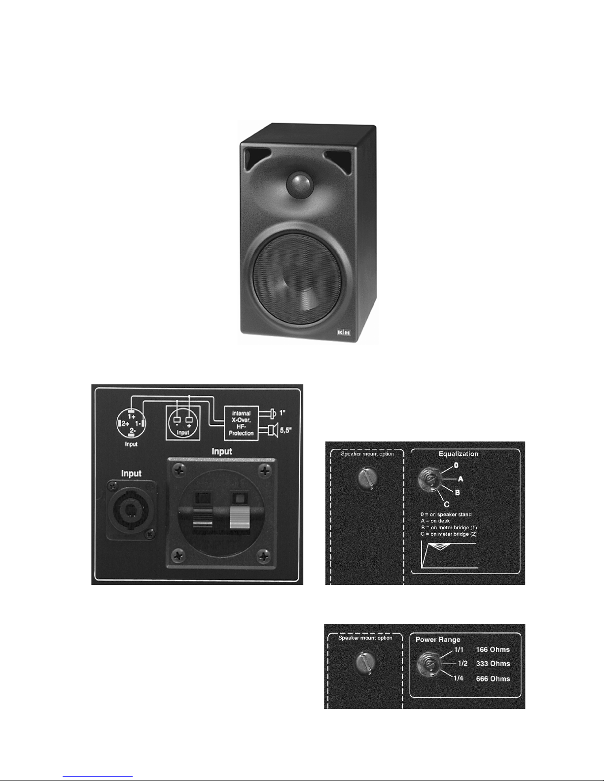
Figure 1: Front view of P 110
Figure 2: Input, P 110/N and P 110/H Figure 3: Room EQ, P 110/N
Figure 4: Power Range, P 110/H
Page 4

Page 4
Introdution
The passive nearfield monitor P 110 has been devived from our active studio monitor O 110 and offers
many of the advantages of the O 110. The P 110 is
offered in a low impedance 8 Ohm version ( P 110/N)
and with a 100 Volt/ 166 Ohm transformer connection
(P 110/H). When only a “P 110“ designation is quoted
in the description below, it is for both models.
Please read the safety instruction on page
2 before connecting the monitor.
1. Installation and Operation
1.1 Operating Conditions
The K + H model P 110 passive nearfield monitor is intended for use over a range of ambient temperatures from +10° C to +40° C (+50°
F to +104° F). During transport or storage, temperatures from -25° C to +70° C (-13° F to
158° F) are permissible.
1.2 Installation
The loudspeaker chassis used in the P 110
are magnetically shielded, allowing these loudspeakers to be mounted side by side with
a video or computer monitor without adversely
affecting the screen. One of the finer features
of the P 110 monitor is its unusually uniform
off - axis directivity, which results in a very wide
”sweet spot”. Preferred placement of the cabinet is in the upright position, for the dispersion
in the verical plane was intentionally kept narrower than in the horizontal.
In certain cases, for example if there are hard,
reflective surfaces both to the left and right of
the loudspeakers, it would make sense to
operate the loudspeakers on their side. The
reduced horizontal directivity in this position
would then be helpful in minimizing any phase
cancellation caused by comb - filter effects.
When considering placement, please take into
consideration the possibilities offered by both
of the room compensation switches described
in section 1.4.
On the back of the unit you will find two M8size threaded bushings for use with various
mounting options. These holes are labeled
”Speaker mount option.” The bushings will accommodate either the LH 32 wall bracket adapter or the LH 31 mounting bracket for use
with additional mounting accessories.
The plastic screws that occupy these
threaded holes from the factory may not
be used for the actual mounting of a
loudspeaker under any circumstances.
Please ensure that these threaded holes are
always plugged so that the volume of air sealed
within the cabinet may only pass through the
precisely calculated bass - reflex openings.
1.3 Connections
For both the 100 V and 8 Ohms models there
are two possible connections on the rear panel:
- SPEAKON
- Speaker terminals
For the SPEAKON connector the contacts 1+
and 1- are provided for theinput signal, as seen
on rear panel. For the speaker terminals the
red contact is provided for the „plus“ wire, the
black contact for the „minus“ wire. Both connectors are wired parallel for looping (plus=red/
minus=black).
1.4 Equalization ( P 110/N only)
The four position rotary switch (Fig.3 in square
“Equalization“) serves to adjust the frequency
response line in order to compensate for varying positions in the room.
Position 0 = “free field“ position
Position A = position on table surface
Position B = position on meterbridge
Position C =position in between other equip-
ment or flush mounted in wall
Important note: Because the studio acoustic will
influence the listening impression at the listenning point we recommend to try all four switch
positions after installation.
The frequency response curves at each switch
position are shown in fig. 11.
1.5 Care of the Cabinet
The cabinet housing of the K + H P 110 active
studio monitor comes standard with a charcoalgrey (RAL color 7021) or white (RAL color 9010)
colored enamel finish. Handle the cabinet with
care to avoid damaging the finish. To clean the
cabinet, use a soft cloth with a mild cleaning
agent only. Under no circumstances should you
use chemical agents or any cleaners with abrasive action.
Page 5

Page 5
2. Diagrams
The outstanding acoustic impression made by the
P 110 is confirmed by measurements using today’s
most critical test methods. The test plots shown here
Using the new material LRIM (Low Resonance Integral
Molding) allowed us to seamlessly integrate a waveguide into the baffle that is ideal for optimal dispersion. So
an elliptical horn for the tweeter was added. Thus came
to be the dispersion pattern we mentioned earlier which
is narrower vertically and broader horizontally, as is clearly evident in the test plots presented in Figure 6 and 7.
and on the next several pages are but a small sampling of these measurements.
Figure 8: Frequency response, (“freefield“) Figure 9: Impedance of P 110/N
Figure 6: Horizontal Directivity
Figure 7: Vertical Directivity
Page 6

Page 6
Figure 10: THD at 95 dB/SPL Figure 11: Cummulative Spectral Decay Plot
The loudspeaker’s cumulative spectral decay plot
indicates a very clean decay without any major
resonances or standing waves being evident.
Figure 12: Meterbridge EQ, P 110/N
3. Warranty Information
All K+H products undergo an extensive procedure of
quality control testing before leaving the factory. Before
semiconductors are mounted on the circuit board, they
are subject to rigorous tests. Every single unit is
guaranteed to match its technical specifications within
strict predetermined tolerances.
Please store the original carton in a safe, dry place. If
you should ever need warranty service, put the unit in
its original packing material and carton together with
a detailed description of the problem, and ship it
(freight prepaid) to our distributor or directly to:
KLEIN + HUMMEL GmbH
Customer service
Zeppelinstrasse 12
73760 Ostfildern / Germany
K+H warrants, that the product is free from any defects
in both material and manufacturing and that it meets
the specifications. A warranty case can only be
acknowledged under condition that the complaint is
filed to our distributor or to us in writing within 8 days
after delivery or detection of the fault. Not covered
under this warranty are damages due to inexpert
packing and shipment, wear and tear, improper
handling, installation, operation and maintenance.
The limitation period for warranty claims is described
in the terms and conditions of K+H GmbH. Its our
choice to repair, to supply a new product or to withdraw
from the contract.
In the event warranty service is required, presentation
of a warranty card will not be necessary. Proof of
purchase date can be made by filing copies of
appropriate documents (invoice, delivery note).
Page 7

Page 7
4. Technical Specifications P 110/N P 110/H
Sensitivity
87 dB/SPL/W/m 86 dB/SPL/W/m
SPL
short term at 1 m (half...)
111,5 dB/SPL 110,5 dB/SPL
Impedance
8
Ω
166/333/666 Ω, switchable
Nominal power handling capacity
80 W 60/30/15 W, switchable
Frequency Range ("freefield)
85 Hz - 20 kHz, ± 2 dB
72 Hz - 24 kHz, ± 3dB
85 hz - 20 kHz, ± 2 dB
72 Hz - 24 kHz, ± 3dB
THD (k
2
and k3 over 150 Hz)
90 dB/SPL at 1m 90 dB/SPL at 1m
Directivity horizontal
± 40° (-6 dB)
± 30° (-6 dB)
± 40° (-6 dB)
± 30° (- 6 dB)
Crossover
Frequency
Slope Woofer
Slope tweeter
3 kHz
12 dB/Okt
18 db/Okt
3 kHz
12 dB/Okt.
18 dB/Okt.
Protection circuitry
HF driver protection against overload
automatic reset
Room compensation EQ
4 steps
Meterbridge posi ti on
-----------------
Drivers
LF/Woofer
HF/tweeter
145 mm, 8
Ω
, Composite-Sandwich-Diaphragm,
25 mm, 6
Ω
, titanium fabric dome
Connectors
1x SPEAKON, 2 speaker termi nals
Dimensions ( WxHxD)
170 x 267x 190mm
Net volume, inside
6,5 Liter
We i g ht
5,0 kg 5,0 kg
Surface finish
anthrazit lackiert (RAL 7021) oder weiss lackiert (RAL 9010)
andere Farben auf Anfrage
Shielding
standard
Mount ing
please read at the newest Studio-Monitoring Catalog
Page 8

K+H Vertriebs- und Entwicklungsgesellschaft mbH
30900 Wedemark, Germany
Phone +49 (5130) 58 48 0
Fax +49 (5130) 58 48 11
www.klein-hummel.com
Printed 11/06 518152
 Loading...