

Page 1
Installation and Operation
Part Number: 519209
Version: 01
Date: 9-Apr-2010
Language: English
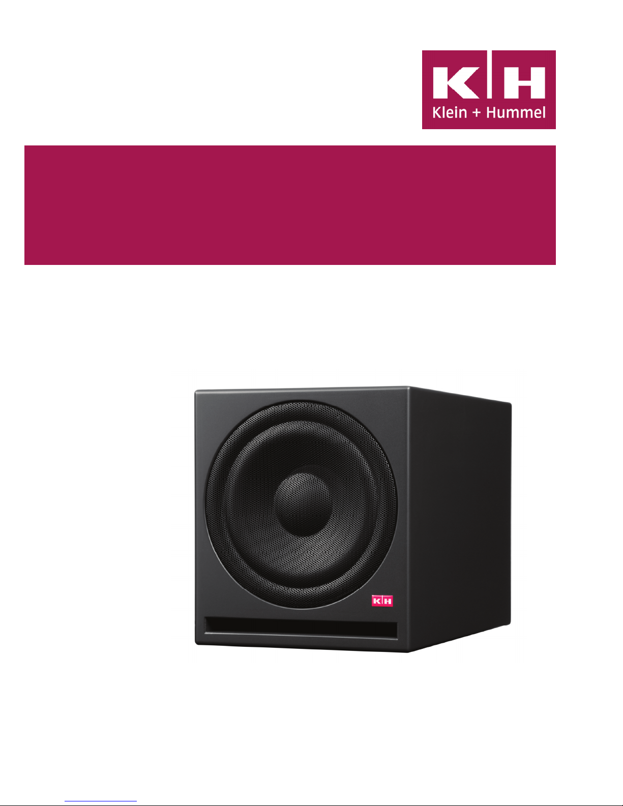
O 800
Active Studio Subwoofer
Page 2
Page 2 Active Studio Subwoofer O800
O 800 Active Studio Subwoofer
Installation - Operation
Figure 1: Front O 800
5
6
7
8
9
10
11
3
13
1
4
12
2
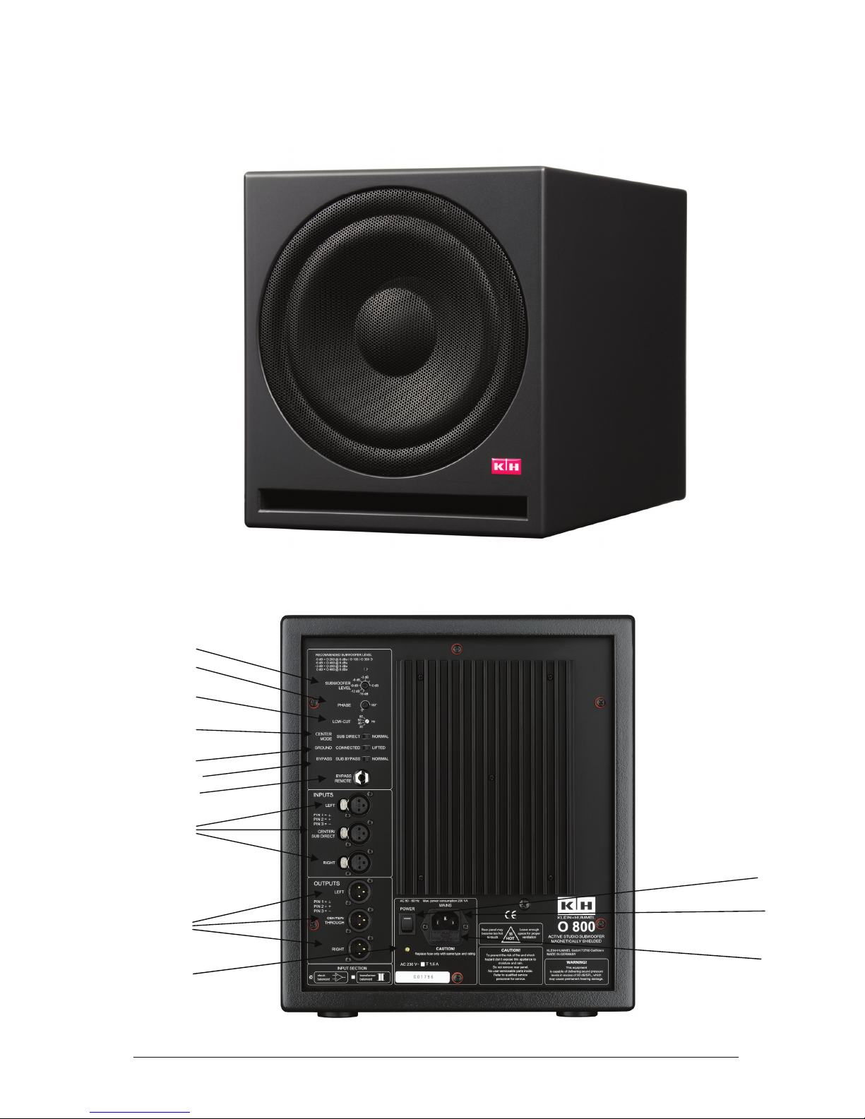
Figure 2: Input section O 800 (rear)
Page 3

Active Studio - Subwoofer O 800 Page 3
1. Connections and Operation
It is absolutely essential that you read and
observe the Safety Instructions in Section 4
before connecting or using this device.
1.1 Operating Conditions
The K+H model O 800 active studio subwoofer
model is intended for use over a range of ambient
temperatures from +10° C to +40° C (+50° F to
+104° F). During transport or storage,
temperatures from -25° C to +70° C (-13° F to
158° F) are permissible.
1.2 Installation
The loudspeaker chassis used in the O 800 is
magnetically shielded, making it possible to set
this unit directly next to a computer without fear
of altering the data on its hard drive. Similarly,
this unit can be positioned under or next to video
or computer monitors without adversely affecting
the screen. The subwoofer is intended to be used
in an upright position, resting solidly on the floor.
If you place the unit near a wall, please leave at
least 8 inches (20 cm) of space before the wall
to ensure proper cooling of the integral amplifier.
1.3 Connection to Mains Current (AC Power)
쐃
The amplifier electronics are set up for an AC
line voltage of 230 volts, 50 or 60 Hz. For export,
special versions with other AC voltages are also
available. If the mains power cable
should ever become damaged, it may
not be repaired, but must be replaced.
1.4 POWER Switch 쐇
When you switch on power to the unit, there is
a three-second delay before the amplified signal
is sent to the subwoofer, as well as to the outputs
for the satellite loudspeakers. This delay avoids
the loud popping sounds that otherwise may be
generated by devices earlier in the signal chain
as power reaches them. You will find this
arrangement particularly useful if your studio uses
a master switch to power up all the equipment
at once. When power on the O 100 is turned
off, on the other hand, or if there is a general
power failure, the signal flow to the speaker is
immediately cut off, preventing any loud pops. A
green LED in the power switch itself indicates
that the unit is switched on and ready to go.
1.5 Inputs 쐋
The sensitivity of the three electronically balanced
inputs is -6 dBu (0.388 volt) referenced to
maximum output of the subwoofer. The setting
has no influence on the audio outputs. The 3-pin
XLR jacks (female) are wired in the standard
manner (pin 1 = ground, pin 2 = +, pin 3 = - ).
The inputs are modular and can optionally be
ordered as transformer-balanced, floating inputs.
1.6 Outputs 쐏
The outputs are electronically balanced and are
intended to be connected to active monitor
inputs. In normal operating mode, the signal at
each channel of these outputs is identical to that
which came into the corresponding input channel,
with the exception that the output signal only
contains information above 90 Hz (also see the
sections Center Mode and Bypass). The 3-pin
XLR jacks, male in this case, are wired in the
standard manner (pin 1 = ground, pin 2 = +, pin
3 = - ).
1.7 Subwoofer Level 쐄
This control pot allows you to adapt the output
volume of the subwoofer to any monitor
loudspeakers, and can be varied within an 18
dB range.
In setting up your subwoofer for best results,In setting up your subwoofer for best results,
In setting up your subwoofer for best results,In setting up your subwoofer for best results,
In setting up your subwoofer for best results,
we urgently recommend that you use thewe urgently recommend that you use the
we urgently recommend that you use thewe urgently recommend that you use the
we urgently recommend that you use the
supplied reference CD (see Section 5), as roomsupplied reference CD (see Section 5), as room
supplied reference CD (see Section 5), as roomsupplied reference CD (see Section 5), as room
supplied reference CD (see Section 5), as room
acoustics and subwoofer placement varyacoustics and subwoofer placement vary
acoustics and subwoofer placement varyacoustics and subwoofer placement vary
acoustics and subwoofer placement vary
widely and therefore demand widely varyingwidely and therefore demand widely varying
widely and therefore demand widely varyingwidely and therefore demand widely varying
widely and therefore demand widely varying
settings.settings.
settings.settings.
settings.
1.8 Subwoofer Phase 쐂
Use this control to adjust for varying distancesUse this control to adjust for varying distances
Use this control to adjust for varying distancesUse this control to adjust for varying distances
Use this control to adjust for varying distances
between the subwoofer and the monitors. Ifbetween the subwoofer and the monitors. If
between the subwoofer and the monitors. Ifbetween the subwoofer and the monitors. If
between the subwoofer and the monitors. If
the loudspeakers are set up the same distancethe loudspeakers are set up the same distance
the loudspeakers are set up the same distancethe loudspeakers are set up the same distance
the loudspeakers are set up the same distance
away fraway fr
away fraway fr
away fr
om each other horizontallyom each other horizontally
om each other horizontallyom each other horizontally
om each other horizontally
, a setting of, a setting of
, a setting of, a setting of
, a setting of
0° is recommended. If the distances are different, you will need to use the reference CD in
order to ensure proper settings.
1.9 Low-Cut Filter 쐆
This four-position switch can be used to set the
low-frequency cut-off point of the subwoofer at
30, 40, 50, or 60 Hz, for example to simulate the
sonic character of ”smaller” loudspeakers. It also
reduces the subwoofer level in steps of
approximately 1 dB.
1.10 Center Mode 쐊
Use this control to switch the center input and
output from Normal mode to broad-band
operation (”sub direct”) if you are using the LFE
output of a surround-sound amplifier. In this
mode, the Center input signal is sent unfiltered
to both the subwoofer and the Center output.
NORMALNORMAL
NORMALNORMAL
NORMAL
In this mode, the signals of all three inputs are
electronically summed and sent through a 90
Hz low-pass filter to the subwoofer. The signal at
the other outputs then has content only above
90 Hz. This is the recommended setting in those
cases where the three front signals (Left, Cen-
Page 4

Page 4 Active Studio - Subwoofer O 800
ter, Right) are going to a surround-sound system.
SUB DIRECTSUB DIRECT
SUB DIRECTSUB DIRECT
SUB DIRECT
In Sub-Direct mode, only the left and right input
signals are electronically summed and sent
through a 90-Hz low-pass filter to the subwoofer,
whereas the signal from the CENTER/SUBDIRECT input is sent to the subwoofer directly
as a broadband signal, i.e. without filtering out
any of the frequency spectrum. This mode would
then allow a second subwoofer to be added for
the purpose of increasing the overall system
output. This operating mode is recommended
when both rear channels are reproduced by way
of Left and Right and the Effect channel is
reproduced by way of the Center/Sub Direct.
1.11 Ground Lift 쐎
Since the inputs are balanced, it should rarely
happen that you encounter problems with hum.
In unusual cases or if the source is unbalanced,
it may become necessary to lift the signal ground
from the chassis ground. To do so, simply move
the GROUND switch to the LIFTED position. In
the CONNECTED position the chassis ground
and the signal ground are connected to each
other by way of a fuse-resistor. However, the
chassis ground always remains connected to the
protective earth conductor of the mains cable.
1.12 Bypass 쐅
Use this switch if you wish to mute the subwoofer
for purposes of evaluating the sound of the system
without any low-frequency reinforcement. In the
position SUB BYPASS, all outputs are fed
broadband signals from their corresponding
inputs (without the 90-Hz high-pass filtering),
whereas in the position NORMAL, the subwoofer
operates in the manner we already described.
1.13 Bypass Remote 쐈
With a standard on/off single-pole footswitch
connected to this jack, you can operate the
bypass function remotely.
Please note that this jack takes precedence over
the BYPASS switch, i.e., when this jack is
occupied by a ¼” phone plug, the BYPASS switch
is disabled.
Footswitch open = NORMAL
Footswitch closed = BYPASS
1.14 Mains Fuse 쐉
When replacing the fuse,
first disconnect thefirst disconnect the
first disconnect thefirst disconnect the
first disconnect the
mains cablemains cable
mains cablemains cable
mains cable and ensure that the new fuse is of
the following type:
for 230 volts AC: 1.6 A Slo-Blo (5 x 20 mm)
for 117 volts AC: 3,15 A Slo-Blo (5 x 20 mm)
for 100 volts AC: 3,15 A Slo-Blo (5 x 20 mm)
1.15 Power Indicator LED 씈
The green LED built into the power switch will
illuminate to confirm that the subwoofer is
operational.
1.16 Care of the Cabinet
The cabinet housing of the K+H O 800 active
studio subwoofer comes standard with an
anthracite-colored enamel finish (RAL color 7021).
Take care when handling the unit not to damage
the finish. To clean the cabinet, use a soft cloth
with a mild cleaning agent only. Under no
circumstances should you use alcohol-based or
chemical agents, nor any cleaners with abrasive
action.
2. Warranty Information
All K+H products undergo an extensive
procedure of quality control testing before leaving
the factory. Before semiconductors are mounted
on the circuit board, they are subject to rigorous
tests. Every single unit is guaranteed to match
its technical specifications within strict
predetermined tolerances.
Please store the original carton in a safe, dry
place. If you should ever need warranty service,
put the unit in its original packing material and
carton together with a detailed description of the
problem, and ship it (freight prepaid) to our
distributor or directly to
K+H warrants, that the product is free from any
defects in both material and manufacturing and
that it meets the specifications. A warranty case
can only be acknowledged under condition that
the complaint is filed to our distributor or to us in
writing
within 8 dayswithin 8 days
within 8 dayswithin 8 days
within 8 days after delivery or detection
of the fault. Not covered under this warranty are
damages due to inexpert packing and shipment,
wear and tear, improper handling, installation,
operation and maintenance.
The limitation period for warranty claims is
described in the terms and conditions of K+H
GmbH. Its our choice to repair, to supply a new
product or to withdraw from the contract.
In the event warranty service is required,
presentation of a warranty card will not be
necessary. Proof of purchase date can be made
by filing copies of appropriate documents (invoice,
delivery note).
3. Diagrams
The outstanding sonic impression made by the
O 800 active studio subwoofer in listening tests
is confirmed by the most advanced technical test
y
your dealer.
Page 5

Active Studio - Subwoofer O 800 Page 5
Figure 3:
Free-field frequency response
measurement in Sub Direct Mode
Figure 4:
Block diagram of the amplifier electronics
measurements available. The following
diagrams reflect but a small portion of these
measurements.
Page 6

Page 6 Active Studio - Subwoofer O 800
4. KLEIN + HUMMEL Surround-Sound Recommendations
KLEIN + HUMMEL believes, that it is very important to maintain the same sonic character across several
loudspeaker lines. This foundation of uniformity ensures, that the various monitors can be used in combination
with each other. Nevertheless, since the size and shape of each cabinet has a significant influence on a loudspeaker’s
dispersion pattern, the monitors can, as a result, sound quite differently depending on where they are placed in
the room.
To achieve optimal results, we therefore recommend, that when you design your surround-sound layout, you
keep the following overview in mind.
4.1 Matrix Surround (Dolby
®
Surround)
Position and loudspeaker type
Front L + R Front Center Rear L + R Subwoofer
Monitor A Monitor B Monitor C
O 110 O 110 M 50 O 800
O 110 O 110 P 110 O 800
O 110 O 110 O 110 O 800
O 200 O 200 O 110 O 800
O 300 D O 300 D O 110 O 800
O 400 O 400 O 110 1 or 2 x O 800
O 400 O 400 O 200 1 or 2 x O 800
Figure 5: Listening room setup in matrix surround
Mixing console
Listening point
Page 7

Active Studio - Subwoofer O 800 Page 7
Front L + C + R
Rear L + R Low Frequency Effects (LFE) Subwoofer
O 110 O 800 O 800
For LFE Optional sub-extension for front chanels
Optional as sub-extension for rear channels
O 200 O 800 O 800
For LFE Optional sub-extension for front channels
Optional as sub-extension for rear chanels
O 300 D O 800 O 800
For LFE Optional sub-extension for front channels
Optional as sub-extension for rear chanels
O 400 O 800 1 or 2 x O 800
For LFE Optional sub-extension for front channels
Optional as sub-extension for rear chanels
4.2 Discrete Surround (AC-3, DTS)
With discrete 5.1 channel surround systems (5 separate main channels + 1 Low Frequency Effects channel) all
main channel monitors are to be of the same type, i.e., Monitor A = Monitor B = Monitor C.
If space is tight in smaller rooms, the next smaller monitor type can be substituted for the rear loudspeakers.
Mixing console
Listening point
Figure 6: Listening room setup in discrete surround
Position and loudspeaker type
Page 8

Page 8 Active Studio - Subwoofer O 800
5. Safety Instructions
It is absolutely essential that you read these safety instructions carefully before connecting and using this K+HIt is absolutely essential that you read these safety instructions carefully before connecting and using this K+H
It is absolutely essential that you read these safety instructions carefully before connecting and using this K+HIt is absolutely essential that you read these safety instructions carefully before connecting and using this K+H
It is absolutely essential that you read these safety instructions carefully before connecting and using this K+H
prpr
prpr
pr
oduct. Yoduct. Y
oduct. Yoduct. Y
oduct. Y
our safety depends on it. Furthermorour safety depends on it. Furthermor
our safety depends on it. Furthermorour safety depends on it. Furthermor
our safety depends on it. Furthermor
e, failure, failur
e, failure, failur
e, failur
e to follow these instructions voids the warrantye to follow these instructions voids the warranty
e to follow these instructions voids the warrantye to follow these instructions voids the warranty
e to follow these instructions voids the warranty
..
..
. To ensure
safe operation for years to come, keep these instructions in a safe place for future reference. K+H has manufactured this
product in accordance with IEC 60065 standards, then tested and delivered it in safe operating condition. To maintain it in this
condition, you must:
• observe all safety instructions,
• use the product only as described herein,
• have any maintenance, repairs, or modifications performed only by K+H or other authorized personnel, and
• ensure that the room in which you use this product is wired in accordance with the local electrical code.
WW
WW
W
arar
arar
ar
ning!ning!
ning!ning!
ning!
• When the interior of the cabinet is exposed, touching some parts can lead to an electric shock.
• If you need to gain access to the interior electronics of the unit, always disconnect the unit from any and all power sources
first.
• Any repairs, maintenance, or other service of the unit when its interior compartment is exposed may
only be performed safely (in accordance with VBG 4) by authorized technicians familiar with all the risks
involved. Even in an unplugged state, a fully charged capacitor in the unit can zap the unsuspecting.
• Loudspeaker output jacks labeled with the IEC 417/5036 emblem (Fig. A, right) may be carrying
dangerously high voltages. If your unit has this emblem, ensure that any connections to be made
between these jacks and the speakers themselves are made before powering up the unit, and are done
so only with manufacturer-approved interconnecting cables.
• If you need to replace any fuses, ensure that the replacements are of exactly the same type, value and
voltage as the originals, as spelled out in the technical specifications at the rear of this manual.
• Do not use "repaired" fuses.
• If you do not have any fuses on hand of the specified size, type, and value, do not hot-wire the contacts
in the holder by short-circuiting them.
• Certain areas of the cabinet, cover, and rear panel can achieve extreme temperatures and are therefore
marked with a "HOT" label (Fig. B). Refrain from touching any heat sink or ventilation grille.
• High volume levels are known to cause permanent - i.e. irreversible - hearing damage, especially when
listened to without sufficient breaks. The higher the levels, the more frequent and extended must be
the breaks. Avoid standing too close to loudspeakers that are being driven at high levels. If you must
be exposed to high sound pressure levels over an extended period of time, use hearing protection.
Mains Connection:Mains Connection:
Mains Connection:Mains Connection:
Mains Connection:
• This unit is designed for continuous operation.
• Ensure that the operating voltage of the unit matches that of the local mains current (AC line voltage).
• Always check before connecting the power cable to the mains socket that the power switch on the unit itself is set to off
("O").
• Use the power cable or power supply that came with the unit to connect to the mains socket (wall outlet).
• Power supply: a damaged power cable may not be repaired. Use a new cable.
• Avoid plugging the mains cable into a power strip that already has several other power-consuming devices connected to
it.
• Avoid using extension cables. The unit must be connected to a mains socket close to it, and that socket should be freely
accessible.
Installation:Installation:
Installation:Installation:
Installation:
• This product may only be placed on a stable, clean, horizontal surface.
• Do not expose this product to vibration.
• Do not operate this product anywhere near water or other liquids. Do not use it near a sink, swimming pool, bathtub, or
in any damp room or area. Electrical shocks carried through water can kill. Do not place any beverages whatsoever on
or near this product, as liquids can kill electronic components.
• Ensure sufficient ventilation around the product to allow for adequate heat dissipation, especially near the rear panel and
the sides of the cabinet (minimum of 8 inches from the nearest wall). The unit may only be installed in a rack if measures
are taken to ensure sufficient ventilation and if the mounting instructions of the manufacturer are followed. Do not block
or cover any heat sink, fan, or vent.
• Do not place the product where it will be in the path of direct sunlight, and keep it a safe distance away from radiators and
other heaters of any kind.
• If you bring this product from a cold environment into a warm one (such as from a vehicle into a studio), it is quite possible
that condensation will form inside the cabinet. Please allow the unit sufficient time for acclimatisation to room temperature
(minimum thirty minutes) before connecting and powering up.
• To avoid accidents, do not use any accessory equipment with this product which is not approved by the manufacturer,
particularly mounting accessories. Do not place this unit on any unstable platform, cart, stand or table. Should the unit fall,
it can cause bodily injury to persons, or can be damaged itself.
• To protect this product from lightning damage during a thunderstorm or from power surges during an extended
absence, disconnect the power cable from the wall outlet.
Fig. A
Fig. B
Page 9

Page 10

Page 10 Active Studio - Subwoofer O 800
Technical specifications O 800
Maximum sound pressure level
in half space, 3% THD at 1 m distance 111.8 dB/SPL
averaged between 40 Hz and 90 Hz
Free-field frequency response 30 Hz - 90 Hz (
+ 2 dB) in Sub-Direct mode
Self generated noise level at 10 cm
< 20 dB(A)
THD @ 95 dB/SPL/1 m < 0.5 % above 30 Hz
Amplifier
Power amplifier section 120 watts into 16 Ohms (THD
< 0.1 %)
Crossover
Crossover point 90 Hz
Slope 24 dB/octave
Limiter prevents overloading of loudspeaker and amplifier
Inputs Left – Center (or LFE signal) – Right
Impedance > 20 kOhm (electronically balanced)
Subwoofer sensitivity - 6 dBu (0.388 V)
CMRR
> 50 dB
Subwoofer Level Control 0 ... -18 dB
Outputs Left – Center (or LFE pass-through) – Right
Impedance 100 Ohms (electronically balanced)
Frequency range 90 Hz - 30 kHz or linear (in Bypass position)
Level same as input signal
Low-cut filter 4-position switch 30 – 40 – 50 – 60 Hz with 18 dB/octave
Phase infinitely variable 0 - 180°
Ground lift switch separating signal ground from chassis ground
Center-Mode – Sub Direct for Dolby 5.1 LFE Normal – Bypass
Woofer 265 mm (10”) Ø, 16 Ohm, cast iron chassis
Magnetic shielding standard
Connections Mains power 3-terminal Euro-norm NK10
Amplifier Inputs 3 x XLR 3-31 (3-pin female jack)
Amplifier Outputs 3 x XLR 3-32 (3-pin male jack)
Bypass Remote Control ¼” phone jack
Power consumption At idle 15 VA
Full output 200 VA
Mains 230 or 117 or 100 volts 50/60 Hz depends on version
Dimensions (W x H x D) 12-5/8” x 14” x 20-7/8” (320 x 354 x 530 mm)
Net volume 32.3 litres
Weight 55 pounds (25 kg)
Cabinet MDF; with metal grille dark grey enamel finish, color: RAL 7021
Recommended K+H monitors O 100, O 104, O 108/TV, O 98, O 198, O 106
O 110, O 200, O 300 D, O 400
Page 11

Other company, product, or service names may be trademarks or service marks of other organizations.
Klein + Hummel reserve the right to change product specifications without notice.
Exceptions and omissions excluded.
K+H Vertriebs- und Entwicklungsgesellschaft mbH
Auf dem Kessellande 4a, 30900 Wedemark, Germany.
Phone: +49 (5130) 58 48 0
Fax: +49 (5130) 58 48 11
E-mail: enquiries@klein-hummel.com
Web site: www.klein-hummel.com Part Number 519209
 Loading...