

Page 1
Operating Manual
Operating ManualOperating Manual
Operating Manual
O 410
Part Number
Part NumberPart Number
Part Number: 526312
Version
VersionVersion
Version: 03
Date
DateDate
Date: 25-Jun-2008
Language
LanguageLanguage
Language: English, Française, Deutsch, Español
O 410
Active
Mid-Field Monitor
Page 2

Page 3

Table of Contents
Table of ContentsTable of Contents
Table of Contents
English
EnglishEnglish
English
Introduction................................................................................................................................................................1
Package Contents......................................................................................................................................................1
Most Common Applications and Listening Distances .......................................................................................1
System Block Diagram .............................................................................................................................................1
Electronics Panel Picture..........................................................................................................................................2
Input Stage .................................................................................................................................................................3
Acoustical Controls....................................................................................................................................................3
Other Controls ............................................................................................................................................................5
Crossover.....................................................................................................................................................................6
Amplifiers....................................................................................................................................................................7
Drivers..........................................................................................................................................................................7
O 410 Mathematically Modeled Dispersion™ Waveguide (MMD™) ..............................................................7
Cabinet.........................................................................................................................................................................8
System Use .................................................................................................................................................................9
Technical Specifications ........................................................................................................................................ 10
Acoustical Measurements .................................................................................................................................... 11
Accessories and Options ....................................................................................................................................... 12
Safety and Warnings............................................................................................................................................. 16
Maintenance and Servicing .................................................................................................................................. 17
Guarantee................................................................................................................................................................. 17
Recycling .................................................................................................................................................................. 17
EC Declaration of Conformity............................................................................................................................... 18
Française
FrançaiseFrançaise
Française
Introduction............................................................................................................................................................. 23
Contenu du carton.................................................................................................................................................. 23
Applications habituelles et distances d’écoute............................................................................................... 23
Synoptique............................................................................................................................................................... 23
Photo du panneau arrière..................................................................................................................................... 24
Étage d’entrée......................................................................................................................................................... 25
Réglages acoustiques............................................................................................................................................ 25
Autres commandes ................................................................................................................................................ 27
Crossover (filtre actif) ........................................................................................................................................... 28
Amplificateurs......................................................................................................................................................... 29
Transducteurs ......................................................................................................................................................... 29
Guide d’onde MMD™ (Mathematically Modeled Dispersion™ Waveguide) de l’O 410 ..........................29
Coffret....................................................................................................................................................................... 30
Utilisation de l’enceinte ........................................................................................................................................ 31
Caractéristiques Techniques ................................................................................................................................ 33
Mesures acoustiques ............................................................................................................................................. 34
Accessoires et Options .......................................................................................................................................... 35
Sécurité et avertissements .................................................................................................................................. 39
Utilisation................................................................................................................................................................. 40
Garantie.................................................................................................................................................................... 40
Recyclage.................................................................................................................................................................. 40
Déclaration de Conformité CE ..............................................................................................................................41
Page 4

Deutsch
DeutschDeutsch
Deutsch
Einleitung ................................................................................................................................................................. 44
Lieferumfang........................................................................................................................................................... 44
Die häufigsten Anwendungen und Hörabstände ........................................................................................... 44
System-Blockdiagramm........................................................................................................................................ 44
Elektronikfeld.......................................................................................................................................................... 45
Input Stage ..............................................................................................................................................................46
Akustikregler/Acoustical Controls...................................................................................................................... 46
Weitere Regler ........................................................................................................................................................ 48
Crossover/Frequenzweiche .................................................................................................................................. 49
Verstärker ................................................................................................................................................................ 50
Treiber....................................................................................................................................................................... 50
O 410 Mathematically Modeled Dispersion™ Waveguide (MMD™) ........................................................... 50
Gehäuse ....................................................................................................................................................................51
Einsatz des Systems .............................................................................................................................................. 52
Technische Daten ...................................................................................................................................................54
Akustische Messungen ......................................................................................................................................... 55
Zubehör und Sonderzubehör............................................................................................................................... 55
Sicherheits- und Warnhinweise .......................................................................................................................... 60
Instandhaltung und Wartung.............................................................................................................................. 61
Garantie.................................................................................................................................................................... 61
Recycling .................................................................................................................................................................. 62
Konformitätserklärung ......................................................................................................................................... 62
Español
EspañolEspañol
Español
Introducción............................................................................................................................................................. 64
Contenido del paquete .......................................................................................................................................... 64
Aplicaciones más comunes................................................................................................................................... 64
Diagrama de conjunto del sistema..................................................................................................................... 64
Imagen del panel de circuitos electrónicos....................................................................................................... 65
Etapa de entrada.................................................................................................................................................... 66
Controles de sonido ............................................................................................................................................... 66
Otros controles........................................................................................................................................................ 68
Crossover.................................................................................................................................................................. 69
Amplificadores ........................................................................................................................................................ 70
Bocinas...................................................................................................................................................................... 70
Guía de onda con Mathematically Modeled Dispersion™ (MMD™)............................................................. 70
Gabinete ................................................................................................................................................................... 71
Uso del sistema....................................................................................................................................................... 72
Especificaciones técnicas ...................................................................................................................................... 74
Mediciones acústicas ............................................................................................................................................. 75
Opciones y accesorios............................................................................................................................................ 76
Instrucciones de seguridad .................................................................................................................................. 80
Servicio y mantenimiento .................................................................................................................................... 81
Garantía.................................................................................................................................................................... 81
Reciclado................................................................................................................................................................... 82
Declaración de Conformidad con las directivas de la Comunidad Europea ............................................... 82
Page 5
Klein + Hummel O 410 Operating Manual
English Page 1 Version 03
Introduction
IntroductionIntroduction
Introduction
Thank-you for purchasing a Klein + Hummel loudspeaker. A Mathematically Modeled Dispersion™ waveguide
(MMD™), flexible acoustical controls, various input options and an extensive mounting hardware range allow the
loudspeaker to be used in diverse acoustical conditions, with any source equipment and in a wide variety physical
locations. The latest acoustical and electrical techniques and components have been used to ensure the most
accurate sound reproduction possible. Klein + Hummel products are designed for longevity so we hope you enjoy
many happy years of using this product.
Depending on the size, Klein + Hummel’s three-way systems are designed for use as near field monitors through
to large main control room monitors. They can be used in music, broadcast, and post production studios for
tracking, mixing, and mastering. They may be positioned used free-standing or flush mounted into a wall, and
can be mixed freely in multichannel systems.
Before reading the rest of this operating manual, review the safety and warnings section towards the back of this
book. Note that imperial dimensions are approximate.
Package Contents
Package ContentsPackage Contents
Package Contents
The shipping carton contains:
• This operating manual
• Product guarantee
• The loudspeaker
• Three mains power cables (Euro, UK, and USA)
• A trimmer and switch screwdriver
Signal cables are not included. Options and accessories are listed at the end of this operating manual.
Most Common Applications and Listening Distances
Most Common Applications and Listening DistancesMost Common Applications and Listening Distances
Most Common Applications and Listening Distances
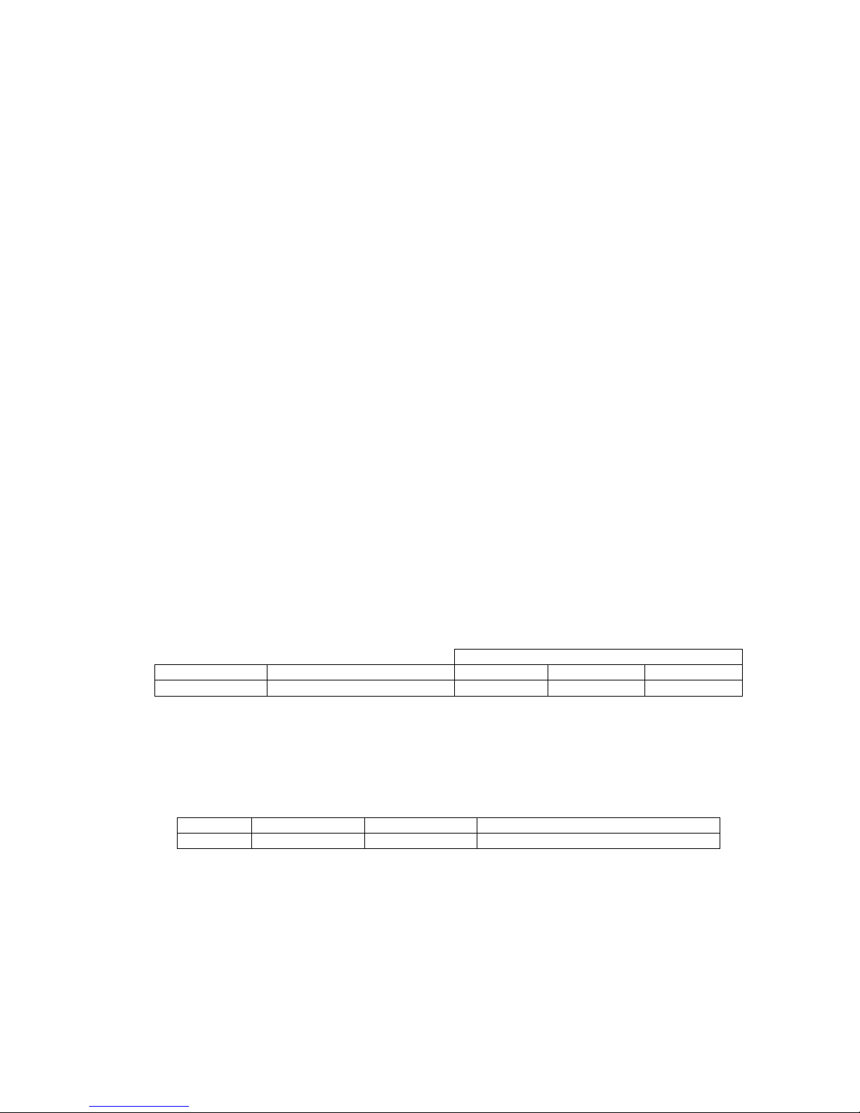
The minimum, recommended, and maximum listening distances are shown below, together with their most
common application:
Di
DiDi
Distances
stancesstances
stances
Product
ProductProduct
Product Most Common Application
Most Common ApplicationMost Common Application
Most Common Application Minimum
MinimumMinimum
Minimum Recommended
RecommendedRecommended
Recommended
Maximum
MaximumMaximum
Maximum
O 410 Mid-field monitoring 1.5 m (5’) 2.5 m (8) 8 m (24’)
In multichannel systems, one should ideally use the same product for all main channels. However, as the rear
channels often contain less bass and the signals are mixed at a lower level than the front channels, the rear
loudspeakers can be smaller - table below for details. The center loudspeaker should always be of the same type
as the left and right loudspeaker. The subwoofer should be sufficient to keep up with the main loudspeakers - see
subwoofer operating manual for details.
Front
FrontFront
Front Ideal Rears
Ideal RearsIdeal Rears
Ideal Rears Smaller Rears
Smaller RearsSmaller Rears
Smaller Rears Subwoofer(s)
Subwoofer(s)Subwoofer(s)
Subwoofer(s)
O 410 O 410 O 300, O 300 D Refer to subwoofer operating manuals
System Block Diagram
System Block DiagramSystem Block Diagram
System Block Diagram
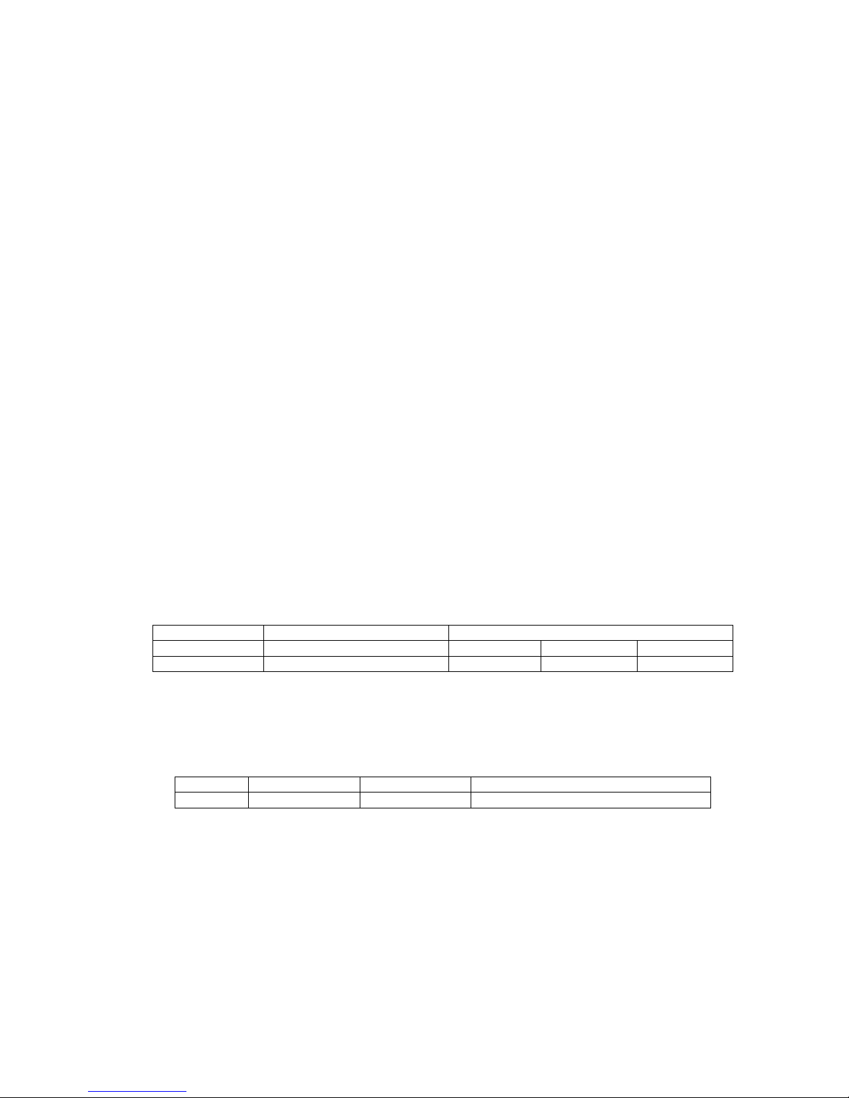
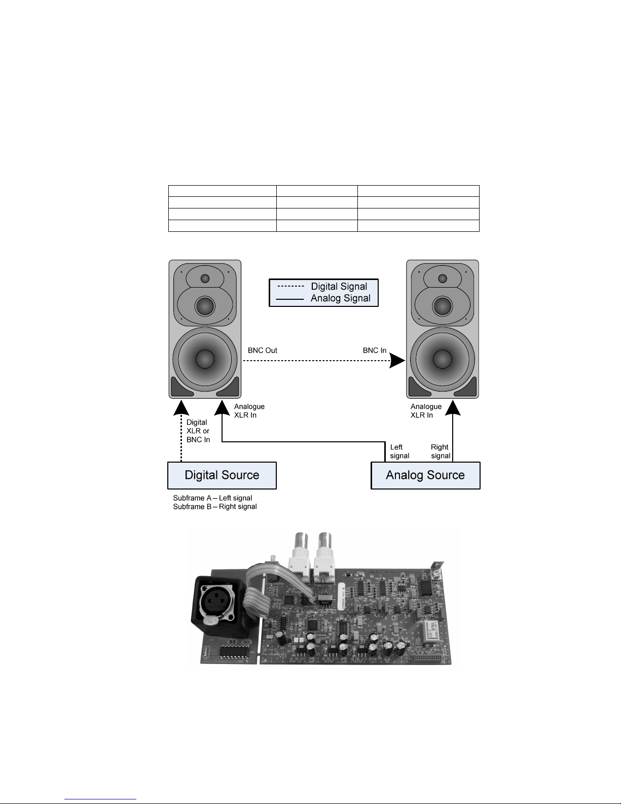
Below is a three-way system block diagram.
Page 6
Klein + Hummel O 410 Operating Manual
English Page 2 Version 03
Refer to the detailed product specifications section for information on the crossover frequencies, amplifier power,
and driver types. In an O 410, the Low Mid / Mid control is a Mid control. As the digital option is user installable,
there is no “D” version of the O 410.
Electronics Panel Picture
Electronics Panel PictureElectronics Panel Picture
Electronics Panel Picture
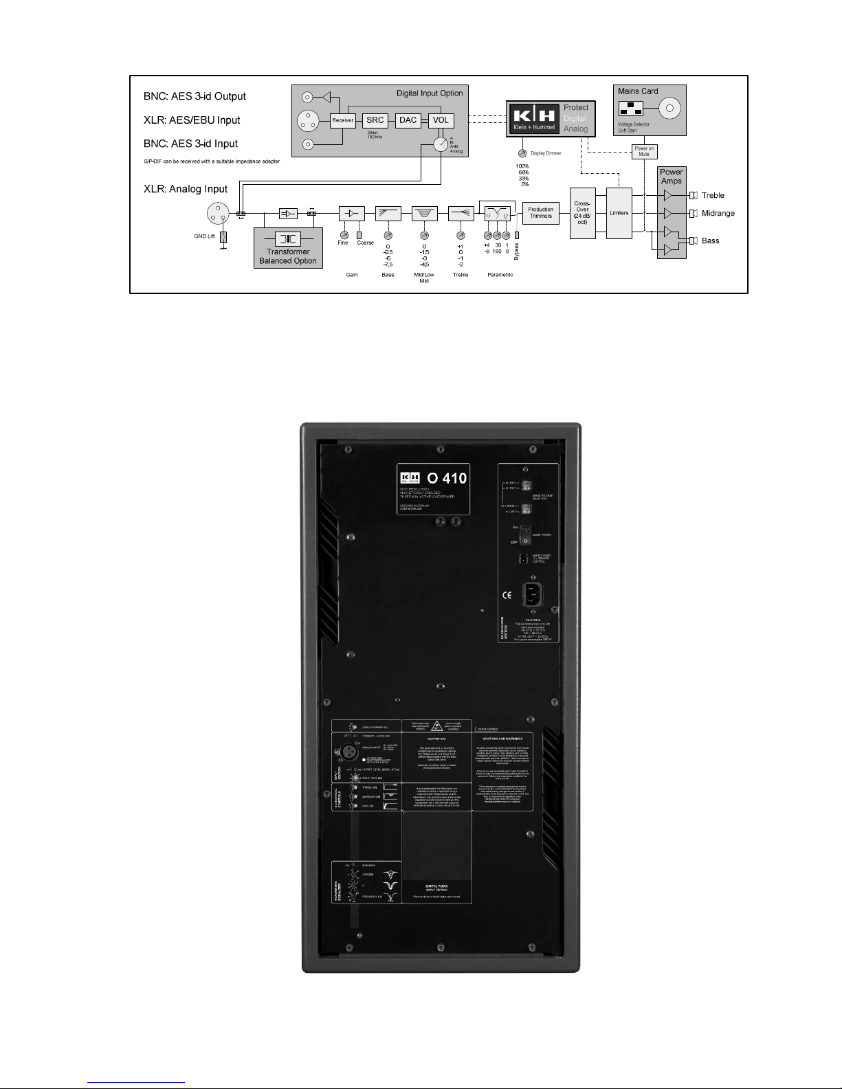
O 410 electronics panel
O 410 electronics panelO 410 electronics panel
O 410 electronics panel
Page 7
Klein + Hummel O 410 Operating Manual
English Page 3 Version 03
Input Stage
Input StageInput Stage
Input Stage
The standard input stage
standard input stagestandard input stage
standard input stage is a 14 kΩ electronically balanced type on a female XLR socket.
Pin
PinPin
Pin Signal
SignalSignal
Signal
1 Audio Ground
2 Positive
3 Negative
If there is a humming or buzzing sound coming from the loudspeaker, first check it is not the loudspeaker by
disconnection the input signal cables. If the noise goes away it is not the loudspeaker itself and so the noises
must be coming from the cabling or the source. There are various ways to increase the loudspeaker’s immunity
from these external noises:
• Use input ground lift switch
input ground lift switchinput ground lift switch
input ground lift switch to disconnect the audio ground, on pin 1 of the analog XLR input, from the
electronics’ chassis ground. For safety reasons, the electronics chassis ground is always connected to the
mains power earth pin.
• Fit an optional transformer balanced input stage
optional transformer balanced input stageoptional transformer balanced input stage
optional transformer balanced input stage to the loudspeaker. This is especially effective when
combined with the ground lift switch.
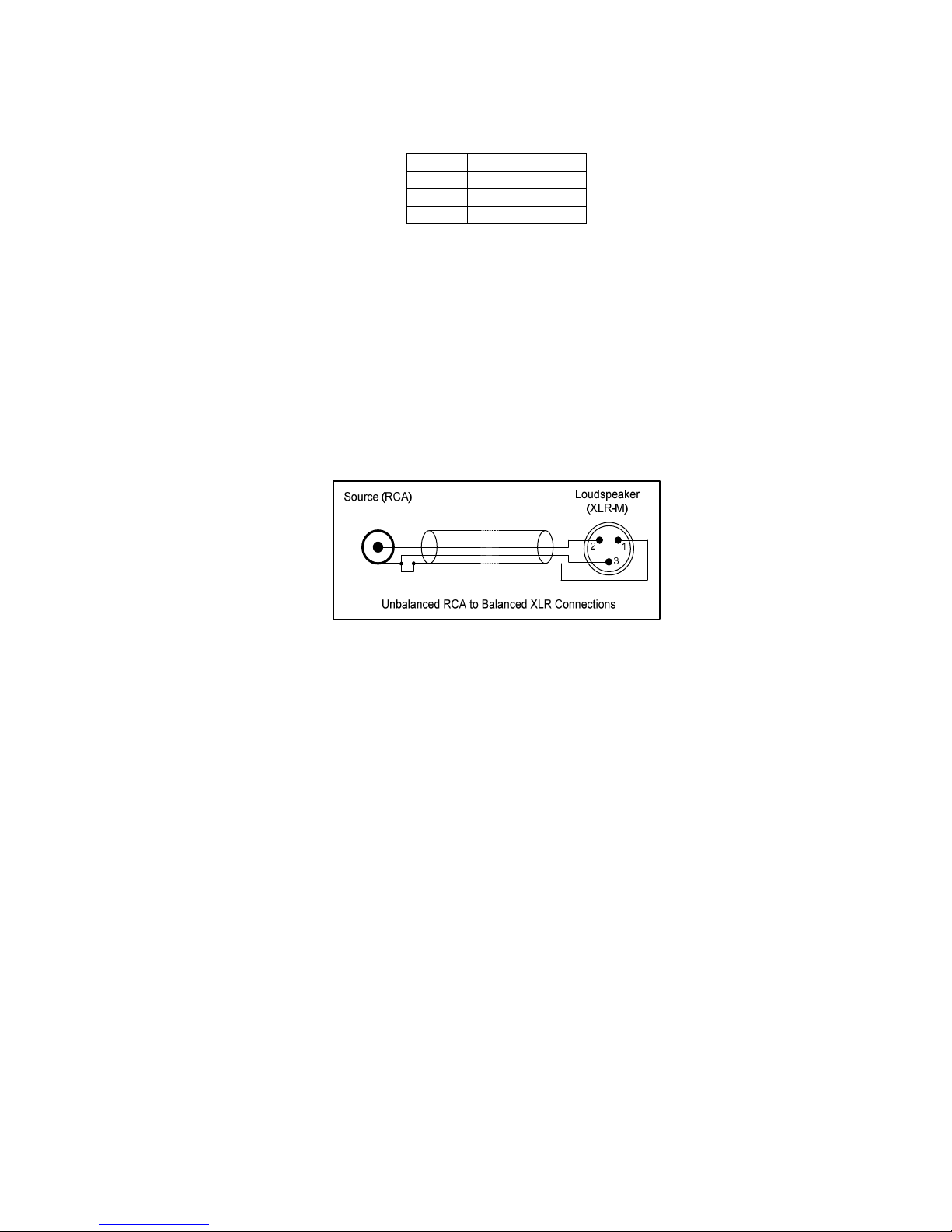
• If unbalanced cables are used, they can be specially wired – see picture below. Disconnect the cable screen
from the RCA sleeve if there are still humming or buzzing sounds, and/or use the ground lift switch on the
loudspeaker.
In addition, it is possible to fit a 24
2424
24----bit, 192 kHz digital input stage
bit, 192 kHz digital input stagebit, 192 kHz digital input stage
bit, 192 kHz digital input stage. It has XLR and BNC inputs, and a BNC output,
so it is possible to have analog and digital signals simultaneously connected; the selector switch is used to
monitor the selected input.
Acoustical Controls
Acoustical ControlsAcoustical Controls
Acoustical Controls
The acoustical controls are low-order analog filters designed to compensate for some of the acoustical issues
commonly found in listening environments. There is either a Low Mid or Mid control depending on the
loudspeaker model. The other controls are seen on all three-way systems.
Klein + Hummel loudspeakers are designed to have a flat pass band magnitude response in anechoic conditions
when all the acoustical controls are set to 0 dB. When a loudspeaker is installed into a listening environment the
response changes and thus should be corrected back to a flat response. It is therefore expected that the controls
will need adjustment to improve the in-situ response of the loudspeaker. The acoustical controls’ settings will
depend on the loudspeaker’s location and will probably be different for the same loudspeaker type installed in
different locations in the same room. In a symmetrical installation, left/right pairs (front or back) will probably
have the same acoustical settings. Suggested settings are shown after this description of the controls:
The bass
bassbass
bass control is used to compensate for the effect of loading due to nearby large solid boundaries such as
walls. Four settings are available: 0, -2.5, -5, and -7.5 dB.
The mid
midmid
mid control (O 410) is used to compensate for strong first order reflections (floor, ceiling, side walls), that
may cause an aggressiveness in the midrange sound quality. A high mid-band reverberation time can also have
this effect and thus be compensated. Four settings are available: 0, -1.5, -3, and -4.5 dB.
The treble
trebletreble
treble control affects the treble driver output level and can be used to compensate for insufficient or
excessive high frequency damping in the room. The treble control is often set to suit the listener’s taste, although
in well-controlled environments there should be little reason to adjust it away from 0 dB. Four settings are
available: +1, 0, -1, and -2 dB.
Page 8
Klein + Hummel O 410 Operating Manual
English Page 4 Version 03
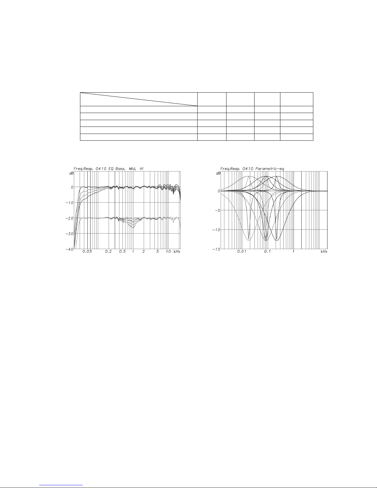
The parametric
parametricparametric
parametric equalizer is a single stage PEQ filter with gain (+4…-12 dB), frequency (20…200 Hz) and Q (1…8)
controls designed to control nonlinearities seen below 200 Hz. These nonlinearities can come from boosts caused
by constructive interference or strong room modes. It is possible to bypass the parametric equalizer using the
bypass switch.
It is advised that an acoustical measurement system be used to set these controls in the most appropriate way
for the loudspeaker’s location. This is especially true of the parametric equalizer’s controls. In the absence of
appropriate equipment the following settings are recommended as a good starting point for further adjustment:
Acoustical Controls
Acoustical ControlsAcoustical Controls
Acoustical Controls
Loudspeaker Location
Loudspeaker LocationLoudspeaker Location
Loudspeaker Location
Bass
BassBass
Bass Mid
MidMid
Mid
O 410
Treble
TrebleTreble
Treble Parametric
ParametricParametric
Parametric
In a corner -7.5 dB - - ***
******
***
Next to or flush mounted in a solid wall -5 dB - - Next to or flush mounted in a soft wall -2.5 dB - - Free standing in an untreated room -2.5 dB -1.5 dB -1 dB ***
******
***
Free standing in a well-treated room - - - -
***
******
*** This indicates that the parametric equalizer will probably need to be used. Its use will depend on the situation
so no standard recommendation can be made here.
O 410 Bass, Midrange and Treble Acoustical Controls
O 410 Bass, Midrange and Treble Acoustical ControlsO 410 Bass, Midrange and Treble Acoustical Controls
O 410 Bass, Midrange and Treble Acoustical Controls O 410 Parametric EQ Acoustical Controls
O 410 Parametric EQ Acoustical ControlsO 410 Parametric EQ Acoustical Controls
O 410 Parametric EQ Acoustical Controls
Note:
Note:Note:
Note: the parametric equalizer’s response is not shown on the above graphs as it is freely adjustable within the
stated parameter ranges.
The input
input input
input and output
output output
output controls consist of a finely graduated control called “Input Gain
Input GainInput Gain
Input Gain” and a coarse “Output
Output Output
Output
Level
LevelLevel
Level” control. This allows the loudspeaker to be matched to a wide range of equipment outputs whilst
maintaining the desired acoustical output. As with any other component in the audio chain, it is best to use the
lowest gain for the application so as to minimize amplification of the preceding equipment’s source noise. To
check this, if the noise drops dramatically when the input cable is unplugged, the noise is coming from the source
not the loudspeaker. The default setting is “0 dB” and “100 dB SPL at 1m”. This gives an output level of 100 dB
SPL at 1m when the input signal is 0 dBu (0.775 V). The most sensitive setting (most acoustical output for a
given input voltage) is “6 dB” and “114 dB SPL at 1m”, and the least sensitive setting is “-9 dB” and “100 dB SPL
at 1m”.
Page 9
Klein + Hummel O 410 Operating Manual
English Page 5 Version 03
Acoustic output level [dB SPL] of the loudspeaker at 1m
Acoustic output level [dB SPL] of the loudspeaker at 1mAcoustic output level [dB SPL] of the loudspeaker at 1m
Acoustic output level [dB SPL] of the loudspeaker at 1m
when input signal is 0 dBu
when input signal is 0 dBuwhen input signal is 0 dBu
when input signal is 0 dBu
Input Sensitivi
Input SensitiviInput Sensitivi
Input Sensitivity
ty ty
ty
Rotary Switch [dB]
Rotary Switch [dB]Rotary Switch [dB]
Rotary Switch [dB]
Output Level switch = “100 dB”
Output Level switch = “100 dB”Output Level switch = “100 dB”
Output Level switch = “100 dB” Output Level switch = “114 dB”
Output Level switch = “114 dB”Output Level switch = “114 dB”
Output Level switch = “114 dB”
-9 dB 91 105
-8 dB 92 106
-7 dB 93 107
-6 dB 94 108
-5 dB 95 109
-4 dB 96 110
-3 dB 97 111
-2 dB 98 112
-1 dB 99 113
0 dB 100 (default) 114
1 dB 101 115
2 dB 102 116
3 dB 103 117
4 dB 104 118
5 dB 105 119
6 dB 106 120
Below are some examples of how to calculate the output level:
Input signal [dBu] 0 (0.775 V) +4 (1.23 V) +6 (1.55 V) +16 (4.89 V)
Input gain setting [dB] 0 0 0 0
Output level setting [dB SPL] 100 100 100 100
Sound Output of Loudspeaker [dB SPL at 1m] 100 104 106 116
In Europe 0 dBu is -18 dBFS (EBU standard R68). In the US +4 dBu is -20 dBFS (SMPTE standard RP155). These
dBu values should equate to 85 dB SPL at the listening position. It is typical in the broadcast industry to use a
reference level of 79 dB SPL at the listening position. Near field loudspeakers can be as close as 1 m from the
listening position, whereas loudspeakers in a Dolby certified movie mixing room should be at least 5 m from the
listening position. In the examples below, it is assumed that the listener is inside the room radius and thus the
sound field decays according to 20 log10 (r), however this may not always be the case. Note that some additional
attenuation at the source (-6 or -10 dB) is required for SPL calibrated near field listening, but this facility is
always available in the console.
Input signal [dBu] 0 (0.775 V) +4 (1.23 V)
Input level setting [dB] -1 -5
Output level setting [dB SPL] 100 100
Listening distance [m] (dB change) 5 m (-14 dB) 5 m (-14 dB)
Loudspeaker Output Level [dB SPL] 85 85
Maximum input signal before clipping 17 dBu 17 dBu
The maximum input level that the input stage can accept is +19 dBu (approximately 6.9 V). To avoid clipping the
input stage, increase the input level of the loudspeaker by up to 6 dB. The maximum acoustical output of the
loudspeaker is limited by the protection system. In general, larger loudspeakers can play louder and for longer
periods than smaller loudspeakers.
Other Controls
Other ControlsOther Controls
Other Controls
The display dimmer
display dimmerdisplay dimmer
display dimmer is used to attenuate the display when the loudspeaker is used in low light situations. The
display can be completely turned off for use behind acoustically transparent screens. Four settings are available:
100, 66, 33, and 0 %.
The power On/Off
power On/Offpower On/Off
power On/Off switch turns the mains power completely on and off. There is a soft start function in the power
supply to reduce the effect of turn-on transients on the power line, thereby avoiding blown fuses.
The voltage selector
voltage selectorvoltage selector
voltage selector switches select between 230, 120, and 100 V. Set this appropriately BEFORE applying main
power to the loudspeaker. An appropriate internal main fuse value is automatically selected. The applied mains
power voltage should be within -15% and +10% of the selected value.
Page 10
Klein + Hummel O 410 Operating Manual
English Page 6 Version 03
The 12 V trigger
12 V trigger12 V trigger
12 V trigger is used to turn the loudspeaker on and off remotely without having the use the mains power
switch. This may be useful in a large facility where the whole room is powered-up using a single switch.
Equipment can be time-delayed using simple low-voltage circuitry so there is not a mains power surge, although
there is already the soft start function to reduce this effect. Note that loudspeaker’s electronics are fully powered
on and off with this control, so the startup time is subject to the same on/off muting delays as if the loudspeaker
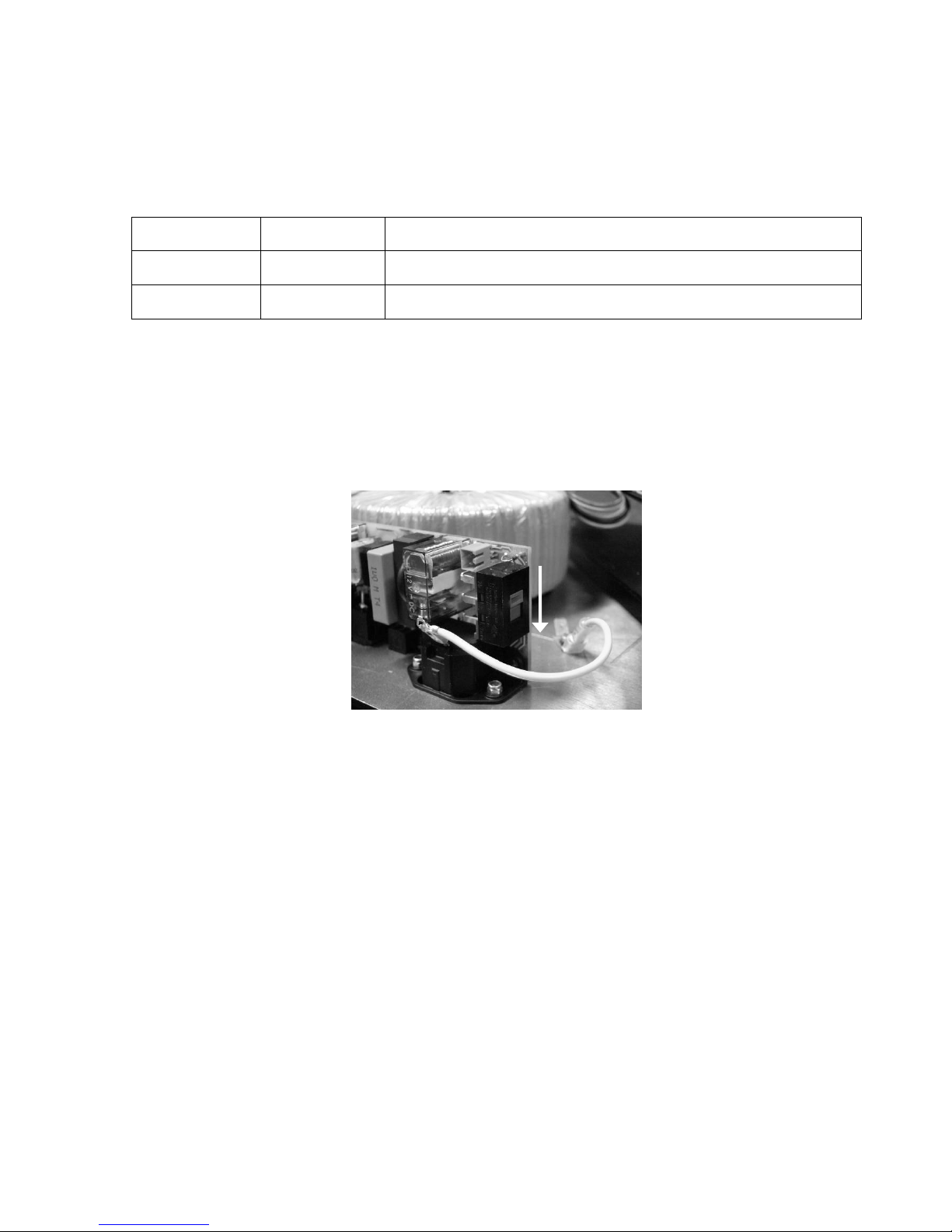
had been turned off and on using the main power switch. There are two modes of operation, which are selected
using an internal switch (see picture below):
Remote Power
Remote Power Remote Power
Remote Power
Mode
ModeMode
Mode
Switch Position
Switch PositionSwitch Position
Switch Position Function
FunctionFunction
Function
“12 V TURNS OFF”
Away from
backplate
Applying 12 V across the remote terminals turns OFF the loudspeaker
Removing the 12 V from the remote terminals turns ON the loudspeaker
“12 V TURNS ON” Towards
backplate
Applying 12 V across the remote terminals turns ON the loudspeaker
Removing the 12 V from the remote terminals turns OFF the loudspeaker
The factory default mode setting is “12 V TURNS OFF”. In both modes and with either applied voltage levels at
the terminals, switching the mains power switch to “OFF” will turn off the loudspeaker.
To change the remote power mode to “12V TURNS ON”:
• Turn off the loudspeaker and disconnect the mains power and signal cables.
• Open the electronics panel (located in the cabinet or remote electronics kit).
• Locate the large switch on the mains power circuit board and move the switch towards the backplate.
• Close the electronics panel and reattach the mains power and signal cables.
• Power up the loudspeaker, apply 12V to the remote control terminals, and check that the appropriate lights
are illuminated.
Crossover
CrossoverCrossover
Crossover
Using 4th order filters, the crossover divides the input signal into three bands for reproduction by the appropriate
sized driver. Time alignment ensures that the sound from each driver around the crossover frequencies is emitted
at the same time. In addition to this an extensive protection system ensures that the loudspeaker is not
damaged if a large signal is applied to the input. The red “PROTECT” lights up when the protection system is
active. If this happens, reduce the input signal. If this happens regularly, use a larger loudspeaker with a higher
SPL output, or add a subwoofer to handle the high-level low-frequency energy. The protection system consists of:
thermal and peak limiters for the amplifiers, thermal modeling of the drivers, and an excursion limiter for the
drivers.
The protection system is not a compressor, it is designed to protect the loudspeaker from damage, and the red
light tells the user it is active. The protection cannot protect against sustained abuse of the loudspeaker, i.e.
consistently playing the loudspeaker for long periods of time with the protect light on, so avoid this to ensure a
long life from this product.
There are also production trimmers in the crossover section which are hidden from view to avoid “accidental”
adjustment. These should only be adjusted by qualified personnel with specialized measurement equipment.
Page 11

Klein + Hummel O 410 Operating Manual
English Page 7 Version 03
If a component critical for sound quality, e.g. bass driver, is changed, the loudspeaker should ideally be
recalibrated in a Klein + Hummel Continental Service Center, i.e. one equipped with an anechoic chamber.
Amplifiers
AmplifiersAmplifiers
Amplifiers
Hybrid class AB amplifiers are used because, for full range loudspeakers, the overall performance is still better
than any other solution. Harmonic and intermodulation distortions, and noise are all consistently low in welldesigned class AB amplifiers. Heat dissipation is reduced by using class H techniques for each amplifier channel to
seamlessly lower the amplifier power supply voltage when the input signal is low. Even so some space (5 cm, 2”)
is required around the electronics panel.
Accelerated Heat Tunneling™ (AHT™) is a technique designed to ensure equally effective cooling of the
amplifiers, whether the cabinet is mounted vertically or horizontally. The “funnel effect” accelerates cool air into
the lower heatsink aperture and expels heated air from the upper heatsink aperture. It is recommended that the
amplifier heatsink is checked for any build-up of dust and fluff at least every six months. The heatsinks can be
cleaned without having to open the electronics panel: simply blow clean compressed air into the vents on the side
of the electronics panel and across the external heatsink. Failure to do this may limit maximum SPL output.
If the cabinet is flush mounted it is highly recommended that the electronics panel be mounted on a Remote
Electronics Kit – see Accessories and Options section. Although no damage will result, insufficient cooling will
cause the amplifier protection to activate prematurely thereby limiting the system’s maximum output level.
Drivers
DriversDrivers
Drivers
The drivers are the best available for their application. Long throw, efficient, low distortion drivers ensure a clean
sound quality even at high replay levels. The bass driver is loaded by the internal volume of the cabinet. The mid
and treble drivers have their own self-contained back cavities. All drivers are magnetically shielded for use next
to CRT screens. The system’s SPL output and the cabinet volume can be seen in the specifications section below.
O 410 Mathematically Modeled Dispersion™ Waveguide (MMD™)
O 410 Mathematically Modeled Dispersion™ Waveguide (MMD™)O 410 Mathematically Modeled Dispersion™ Waveguide (MMD™)
O 410 Mathematically Modeled Dispersion™ Waveguide (MMD™)
The midrange and treble drivers are mounted into a Mathematically Modeled Dispersion™ waveguide (MMD™).
The MMD™ is made from the same acoustically excellent material used in the O 300, LRIM™. It has been
mathematically modeled and experimentally verified in an anechoic chamber to give optimum control of the
directivity of the midrange and treble drivers. The benefits are increased driver loading, reduced edge diffraction
and room reflections, a smoother power response and a wide useable listening area. The result is a reduced audio
distortion and a corresponding sound quality improvement. The MMD™ has 80° x 60° dispersion and so, if the
loudspeaker is horizontally mounted, must be rotated 90° in either direction from the position it which it was
supplied. A rotated waveguide allows the bass driver to be placed either side of the MMD™. If the cabinet is
positioned upside down, the MMD™ should also be upside down to maintain an optimum midrange-bass
crossover region. As the display text is then upside-down, please contact K+H in Germany directly to get a
replacement display sticker with upside-down text. In all cabinet orientations, the acoustical axis should point
towards the engineer’s listening position, or the center of the listening area, in both the horizontal and vertical
planes – see Cabinet section for a definition of the acoustical axis.
This is how to rotate the MMD™:
• Lay the loudspeaker cabinet on its back on a soft flat surface so the drivers are facing upwards.
• Undo the four Allen head bolts on the MMD™ using a T4 Allen head screwdriver.
• Carefully lift the MMD™ out of the cabinet, avoiding scratches on the paintwork and damage to the sealing
strip.
• Reposition the MMD™ in the new orientation and centre it in the front panel cut-out.
• Tighten the four Allen head bolts on the MMD™ to a torque setting of 3,7 Nm (2,73 lbf-ft).
• Test the cabinet sealing by playing a reasonably loud (so you can feel some wind through the ports) sine
wave with a frequency equal to the loudspeaker’s -3 dB low frequency cut off (see specifications below).
Then listen for any hissing sounds around the edge of MMD™ and its drivers. If there is a hissing sound, the
sealing has been compromised and should be repaired.
Page 12
Klein + Hummel O 410 Operating Manual
English Page 8 Version 03
x
y
Cabinet
CabinetCabinet
Cabinet
The wooden cabinet is painted using a standard RAL color. An appropriately colored pen can be used to touch up
the paintwork if it is scratched during transport or use. The following RAL numbers correspond to K+H standard
cabinet colors.
K+H Color Name
K+H Color NameK+H Color Name
K+H Color Name RAL Number
RAL NumberRAL Number
RAL Number
Anthracite 7021
Silver 9006
Combined with the cabinet volume, the ports load the bass driver to extend the low frequency response of the
loudspeaker. The ports have a high capacity to move air without inducing turbulence and associated
nonlinearities that degrade the sound quality.
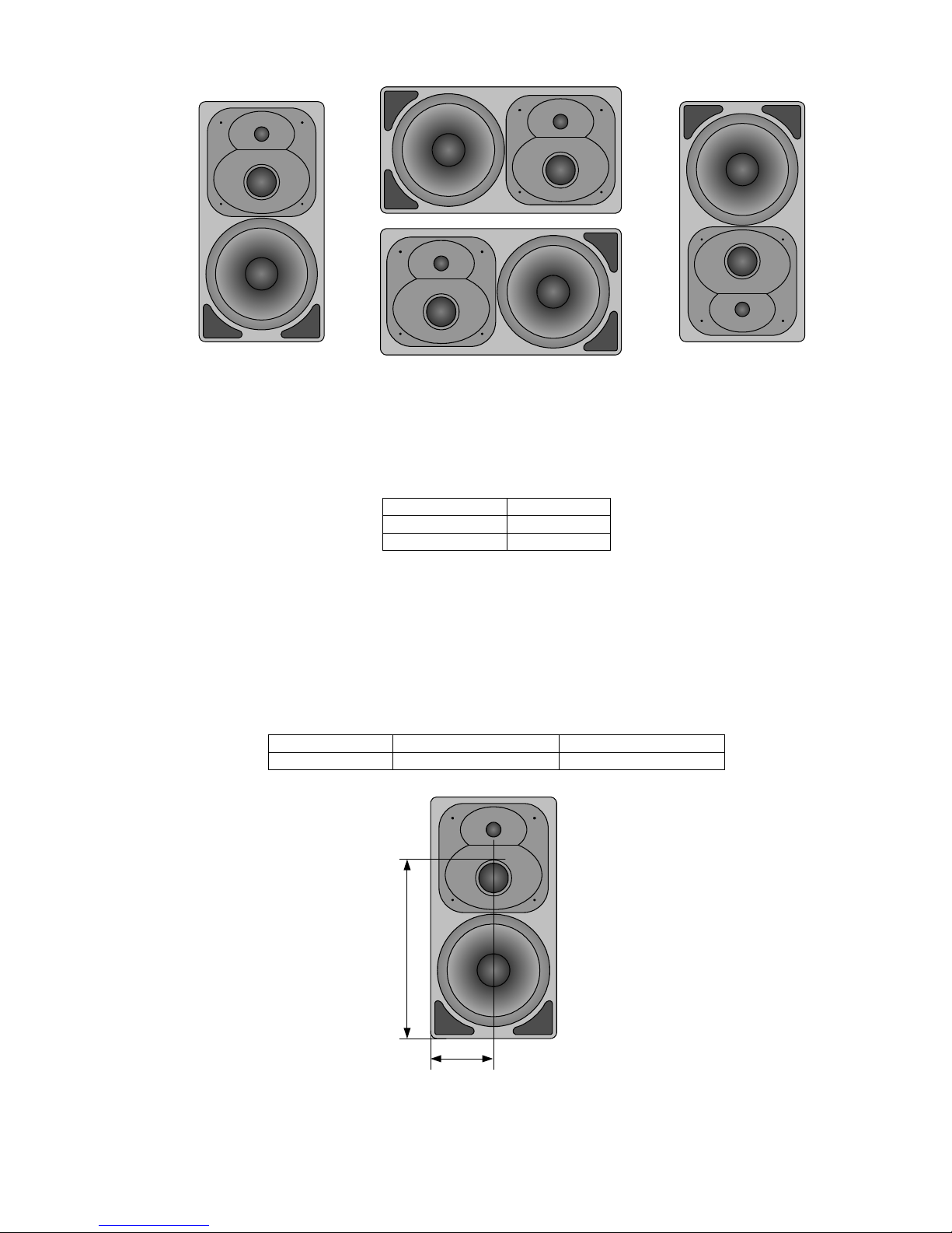
The acoustical axis is a line normal to the loudspeaker’s front panel along which the microphone was placed when
tuning the loudspeaker’s crossover during design. Pointing the acoustical axis, in the horizontal and vertical
planes, towards the listening position or centre of the listening area will give the best measured and perceived
sound quality. For three-way loudspeakers in the Klein + Hummel range, the acoustical axis is located on the midpoint of the midrange and tweeter drivers.
Product
ProductProduct
Product x dimension
x dimensionx dimension
x dimension y dimension
y dimensiony dimension
y dimension
O 410 16.5 cm (6 1/2“) 51 cm (20 1/8“)
O 410 Acoustical Axis
O 410 Acoustical AxisO 410 Acoustical Axis
O 410 Acoustical Axis
Page 13
Klein + Hummel O 410 Operating Manual
English Page 9 Version 03
System Use
System UseSystem Use
System Use
Klein + Hummel loudspeakers should only be used indoors and in these ambient conditions:
• +10° C to +40° C (+50° F to +104° F), <90% relative humidity, non-condensing
During transport or storage the ambient conditions can be:
• -25° C to +70° C (-13° F to 158° F), <90% relative humidity, non-condensing
Before connecting the mains power cable, ensure that the correct mains voltage is selected on the electronics
panel (230, 120, or 100 V) and that the mains power switch is off. Next connect the input signal cable (analog,
digital, or both as appropriate) and power up the loudspeaker. There will be a five second delay before sound can
be heard from loudspeaker so as to avoid noises (pops) from preceding equipment turned on at the same time.
Conversely, turning off the loudspeaker immediately mutes the audio. The K+H logo should light up together
with either the green or yellow light to indicate an analog or digital signal. If there are no lights, check the mains
power supply and the display dimmer (ensure it is not set to 0 %).
In a studio application, the loudspeakers should be placed according to the ITU-R BS.775-1 recommendations so
there is consistency of reproduction when compared to other listening environments. For movie applications,
ANSI/SMPTE 202M is the preferred standard for system setup. For home use, as materials are mixed in ITU style
rooms, one should get as close as possible to this configuration to maximize replay authenticity.
Loudspeaker Name
Loudspeaker Name Loudspeaker Name
Loudspeaker Name ITU
ITUITU
ITU----R BS.775
R BS.775R BS.775
R BS.775----1 Angle
1 Angle1 Angle
1 Angle ANSI/SMPTE 202M
ANSI/SMPTE 202MANSI/SMPTE 202M
ANSI/SMPTE 202M
Angle
AngleAngle
Angle
Left -30° -22.5°
Center 0° 0°
Right 30° 22.5°
Left Surround -110°±10° An array to the left
Right Surround 110°±10° An array to the right
For two-channel stereo, ±30° should be used. There are currently no internationally agreed standards for 6.1 or
7.1 formats. However common practice is to use one or two loudspeakers in the centre back location of a 6.1
system. In a 7.1 system common practice is to place side loudspeakers at ±90° and to push the surround
loudspeakers back to ±150°.
For the best stereo imaging the loudspeakers should be placed symmetrical in a symmetrical room where objects
have been placed symmetrically. This ensures the same response from each loudspeaker at the listening position
and thus good imaging. Sound reflected back to the listening position should also be minimized using surface
angling or acoustical treatment. The acoustical axis point towards the listening position or centre of the listening
area in both the horizontal and vertical planes.
The loudspeaker should be placed on a circle to ensure equal time of arrival of the audio from all loudspeakers.
Failing this, appropriate electronic time delays should be added to compensate for time of flight differences.
If the loudspeaker is used free standing, good quality loudspeaker stands and suitable accessories (see
Accessories and Options section) are recommended.
The benefits of flush mounting are reduced cabinet edge diffraction (smoother midrange), increased bass driver
loading (reduced bass distortion), and elimination of rear wall cancellations (smoother bass response). It is a
good idea to employ an experienced acoustic engineer to design an effective flush mounting wall. Recommended
acoustical control settings are shown in the Acoustical Controls section and a Remote Electronics Kit, shown in the
Accessories and Options section, is highly recommended to avoid heat dissipation problems and allow easy
adjustment of the controls. If the loudspeaker must be covered, use a thin open weave cloth. Two layers of very
thin material will improve opacity.
Before trimming the levels, calibrate each loudspeaker’s response:
• In studio applications, the response of each loudspeaker at the listening position should be flat.
• In movie applications, the response of each loudspeaker should be one of the X-curve shapes, depending on
the size of the room (see ANSI/SMPTE 202M).
• In home applications, the response of each loudspeaker should be set for subjective audio quality. This is not
necessarily a flat response, but generally, with time, a gently downward sloping response with increasing
frequency is often preferred.
Page 14
Klein + Hummel O 410 Operating Manual
English Page 10 Version 03
Absolute acoustic level calibration is achieved using a sound level meter set to ‘C’-weighting and a “slow”
integration time. Play a broadband pink noise test signal set to -18 dBFS (Europe) or -20 dBFS (USA) on the
console meters and measure the sound pressure level at the listening position. Then adjust each channel’s level
(can also be adjusted on all loudspeakers for a specific channel) until the desired level is achieved:
Application
Application Application
Application SPL
SPLSPL
SPL
Movie 85 dB(C)
Broadcast 79 dB(C)
Music Engineer’s preference
For information on setting up a subwoofer with these main loudspeakers, please refer to the operating manual
supplied with the subwoofer.
Technical Specifications
Technical SpecificationsTechnical Specifications
Technical Specifications
Acoustics
AcousticsAcoustics
Acoustics
-3 dB free field frequency response 30 Hz … 24 kHz, ± 3 dB
Pass band free field frequency response 32 Hz … 20 kHz, ± 2 dB
Self-generated noise
≤25 dB(A) at 10 cm
Sine wave output with a THD < 0.5 % at 1 m distance 95 dB SPL (>100 Hz)
Max. SPL In half space at 3% THD 120.0 dB SPL
Averaged between 100 Hz and 6 kHz
Electronics
ElectronicsElectronics
Electronics
Woofer amplifier, cont.(peak) output power* 340 W (400 W)
Mid amplifier, cont. (peak) output power* 160 W (190 W)
Tweeter amplifier, cont.(peak) output power* 180 W (210 W)
Controller design analog, active
Crossover Frequency 600 Hz/2.2 kHz
Crossover Slope (dB/oct.) 24
Equalization: Low cut –
Bass 0, -2.5, -5, -7.5 dB
Mid 0, -1.5, -3, -4.5 dB
High +1, 0, -1, -2 dB
Parametric Equalizer: Bypassable
Gain +4 … -12 dB
Frequency 20 … 200 Hz
Q 1 … 8
Time of Flight adjustment delay –
Protection circuitry Limiter: low, mid, high
Infrasonic filter frequency; slope 15 Hz; 12 dB/oct.
Analog In
Analog InAnalog In
Analog Input
putput
put
Impedance, electrically balanced
XLR, 13 kΩ
Impedance, transformer balanced
XLR, 4.7 kΩ, optional
Input sensitivity -8 dBu / +6 dBu
Attenuator -9 … + 6 dB
CMRR >60 dB @ 15 kHz
Digital Input/Output
Digital Input/OutputDigital Input/Output
Digital Input/Output Optional
Format XLR (Format BNC) AES/EBU (AES3id, S/P-DIF)
Impedance XLR, balanced
110 Ω
Impedance BNC, unbalanced
75 Ω (input and output)
Input switching Analog/Digital A, B, Mono
Digital converter: resolution, design
16 … 24-bit DAC, ∆Σ
sampling rate 20 … 216 kHz (SRC)
Displays and Mains Power
Displays and Mains PowerDisplays and Mains Power
Displays and Mains Power
Displays and indicators: power on K + H logo “red”
limit/clip Red LED
display Green (Analog signal),
Yellow (Digital signal, error)
Mains power 230, 120, 100 V AC
Power consumption - Idle 36 VA
Power consumption - Full output AC 1300 VA
Mechanics
MechanicsMechanics
Mechanics
Height x width x depth, mm 645 x 330 x 444 mm
inches 25 3/8” x 13” x 17 1/2”
Internal net volume 42 liters
Weight 36.0 kg (79.2 lb)
Page 15
Klein + Hummel O 410 Operating Manual
English Page 11 Version 03
Drivers Magnetically shielded
Woofer 10", 250 mm
Midrange 3", 76 mm
Tweeter 1", 25 mm
Mounting points Threaded inserts on rear
Mounting hardware included –
Cabinet surface finish Painted
Color: standard Anthracite or silver
Color: custom at extra cost –
Baffle cover Optional metal grille
*THD+N < 0.1 % with limiter deactivated
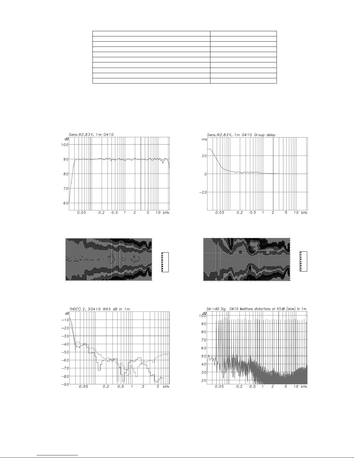
Acoustical Measurements
Acoustical MeasurementsAcoustical Measurements
Acoustical Measurements
Below are acoustical measurements conducted in anechoic conditions at 1 m. Color versions of these graphs can
be found on the appropriate product page of the klein-hummel.com web site.
O 410 free
O 410 freeO 410 free
O 410 free----field response
field responsefield response
field response O 410 group delay
O 410 group delayO 410 group delay
O 410 group delay
125 250 500 1000 2000 4000 8000 16000
-90ø
-60ø
-30ø
0ø
30ø
60ø
90ø
Grad
3-6
0-3
-3-0
-6--3
-9--6
-12--9
-15--12
-18--15
-21--18
125 250 500 1000 2000 4000 8000 16000
-90ø
-60ø
-30ø
0ø
30ø
60ø
90ø
Grad
3-6
0-3
-3-0
-6--3
-9--6
-12--9
-15--12
-18--15
-21--18
O 410 horizontal directivity plot
O 410 horizontal directivity plotO 410 horizontal directivity plot
O 410 horizontal directivity plot O 410 vertical
O 410 verticalO 410 vertical
O 410 vertical directivity plot
directivity plot directivity plot
directivity plot
O 410 harmonic distortion at 95 dB SPL
O 410 harmonic distortion at 95 dB SPLO 410 harmonic distortion at 95 dB SPL
O 410 harmonic distortion at 95 dB SPL O 410 intermodulation distortion at 95 dB SPL
O 410 intermodulation distortion at 95 dB SPLO 410 intermodulation distortion at 95 dB SPL
O 410 intermodulation distortion at 95 dB SPL
Page 16
Klein + Hummel O 410 Operating Manual
English Page 12 Version 03
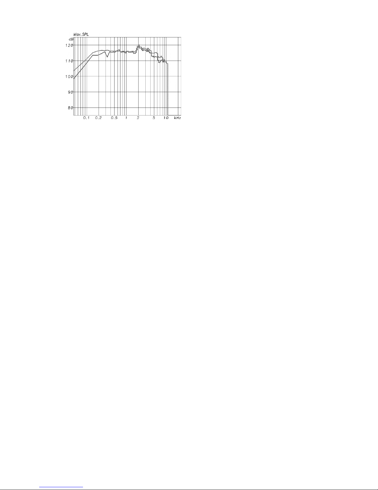
O 410 m
O 410 mO 410 m
O 410 max
axax
aximum
imumimum
imum SPL at 3 % and 10 % THD
SPL at 3 % and 10 % THD SPL at 3 % and 10 % THD
SPL at 3 % and 10 % THD
Accessories and Options
Accessories and OptionsAccessories and Options
Accessories and Options
In this section is a description of the options and accessories that are available for the products covered in the
operating manual. Note that options and accessories are fitted at the user’s own risk and that safety and
warning instructions should be observed.
Transformer balanced input module option (TIM 1)
Transformer balanced input module option (TIM 1)Transformer balanced input module option (TIM 1)
Transformer balanced input module option (TIM 1)
This option changes the electronic balanced input into a transformer balanced input for increased noise
immunity, especially when used in conjunction with the ground lift switch. The circuitry is based on a current
transformation with a THD less then -100 dB @ 16 dBu input level, even down to 20 Hz. It can be used in
conjunction with the digital input option when “Analog” is selected.
Digital input module option (DIM 1)
Digital input module option (DIM 1)Digital input module option (DIM 1)
Digital input module option (DIM 1)
This option is a 16…24-bit, 20…216 kHz digital input stage that can accept AES3-2003 (commonly known as
AES/EBU), AES3id-2001, and S/P-DIF (with a suitable impedance adapter or connector converter) signals. XLR
and BNC connectors ensure good interconnectivity options. A buffered BNC output is provided for connecting
additional loudspeakers to the same cable – a user supplied 75 Ω BNC terminated coaxial cable is required for this
(same cable type as used for word clock signals). The BNC output provides an electronically buffered copy of the
input data, but in AES3id format. The BNC input stage has an internal 75 Ω termination so T-pieces and
terminators are not required. A four-way switch allows selection of:
• “Analog
AnalogAnalog
Analog” input (electronic, or transformer if it is fitted)
• Digital subframe “A
AA
A”
• Digital subframe “B
BB
B”
• Digital subframes A and B simultaneously “M
MM
M” (mono). Note: output level is automatically attenuated by 6
dB to avoid clipping and have the same loudness as a single channel reproduction (A or B).
It is possible to have an analog and a digital cable simultaneously connected to the loudspeaker. The input
selector switch is used to monitor the selected input. Only one of the digital inputs (XLR or BNC) should be
connected at a time. A clock input is not required because loudspeakers are not audio sources and the clock signal
is locally regenerated from data contained in the bit stream.
User-bit volume control (IEC 60958-1) is supported so that the source can directly control the output level of the
loudspeaker whilst using digital signals normalized to full scale. The digital volume control occurs in the analog
domain, thereby offering full bit resolution and improved reproduction at low replay levels. The source must also
support this standard for it to work – see information provided by the manufacturer of the source to see how it
has been implemented.
De-emphasis is supported on 32, 44.1, and 48 kHz sample rates.
Page 17
Klein + Hummel O 410 Operating Manual
English Page 13 Version 03
An interconnection example is shown below. To listen to the analog source, set both loudspeakers to “Analog”. To
listen to the digital source, set the left loudspeaker to “A” and the right loudspeaker to “B” (note the signal
routing in the source).
If the analog input is selected (Analog), the green light on the MMD™ display illuminates. If the digital input is
selected (A, B, or M), the yellow light on the MMD™ display illuminates. The yellow light does not illuminate if
there is no valid word clock on either digital input (note: the green light will also be off in this state as a digital
input has been selected). If there is an error in the digital signal, the yellow light will flash. If this happens check
the cables and connectors, and the source equipment. If there are no lights on, check that mains power is applied
and that the display dimmer switch is not set to 0%. Always use good quality cables with the correct impedance
to achieve these maximum cable lengths:
Format (Connector)
Format (Connector)Format (Connector)
Format (Connector) Impedance
ImpedanceImpedance
Impedance Cable Length
Cable LengthCable Length
Cable Length
S/P-DIF (RCA)
75 Ω
up to 10 m (30’)
AES3 (XLR)
110 Ω
up to 100 m (300’)
AES3id (BNC)
75 Ω
up to 1000 m (3000’)
Warning:
Warning:Warning:
Warning: The digital input option’s BNC connectors protrude from the rear panel. If the O 410 cabinet is placed on
a flat hard surface with the drivers facing upwards, the circuit board will be damaged. Find a soft surface, such as
bubble wrap, packing foam, or a folded blanket, or angle the cabinet slightly to avoid applying pressure to the
BNC connectors.
Page 18
Klein + Hummel O 410 Operating Manual
English Page 14 Version 03
Remote electronics kit option (REK 1)
Remote electronics kit option (REK 1)Remote electronics kit option (REK 1)
Remote electronics kit option (REK 1)
This is a hardware kit to allow the electronics panel to be located up to 30 m (90’) away from the loudspeaker
cabinet. The benefits enjoyed when loudspeakers are flush mounted are: lack of heat dissipation problems, easy
adjustment of the controls, and easier electronics servicing. An 8-pole Speakon terminated cable carries the
driver signals and a CAT-5 cable carries the display signals. Additional space is not required behind the cabinet as
the connectors face downwards when installed. The connections are as follows (note: “Bass 2” is not used when
there is only one bass driver in the cabinet):
Drivers
DriversDrivers
Drivers Speakon Pins
Speakon PinsSpeakon Pins
Speakon Pins Display
DisplayDisplay
Display RJ
RJRJ
RJ----45 Pins
45 Pins45 Pins
45 Pins
Bass 1-/+ 1 -/+ K+H Logo -/+ 1 & 2
Bass 2-/+ 2 -/+ Red -/+ 3 & 4
Midrange -/+ 3 -/+ Yellow -/+ 5 & 6
Treble -/+ 4 -/+
Green -/+ 7 & 8
The cabinet’s serial number is printed under the bass ring – pull it gently by hand to remove it – so it is visible
when the cabinet is flush mounted. This number should be matched to the serial number printed on the remote
located electronics panel.
Cable pack (CP nn)
Cable pack (CP nn)Cable pack (CP nn)
Cable pack (CP nn)
A CAT-5 and 8-core driver cable of length 2, 5, 10, 15, 20, 25, and 30 m (6’, 15’, 30’, 45’, 60’, 75’, and 90’) are
available from Klein + Hummel (Cable Pack 2, 5, 10, 15, 20, 25, or 30), or industry standard cables may be
sourced from a third party. The Klein + Hummel cables use flame retardant materials and high-quality metal
connectors (Neutrik EtherCon NE8MC and Neutrik Speakon NLT8FX). The conductor specification is shown in the
table below:
Length
LengthLength
Length Wire Gauge
Wire GaugeWire Gauge
Wire Gauge
<=20 m (60’) 2.5 mm2 (14 AWG)
>20 m (60’) 4 mm2 (12 AWG)
Mounting hardware (LH nn)
Mounting hardware (LH nn)Mounting hardware (LH nn)
Mounting hardware (LH nn)
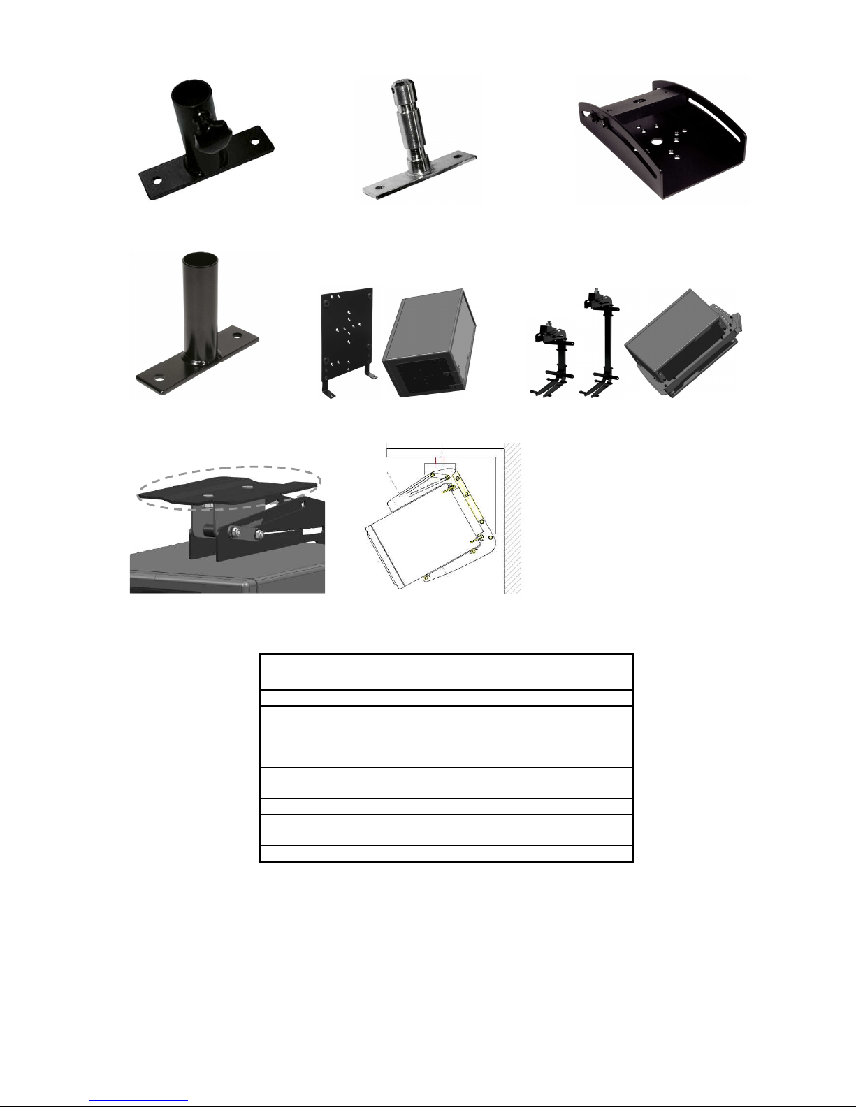
A collection of hardware for mounting the loudspeaker:
LH 28 Tripod stand adapter
Tripod stand adapterTripod stand adapter
Tripod stand adapter – used to fit the loudspeaker onto a standard 1.4” tube tripod stand (external fit
with screw thread).
LH 29 TV spigot adapter
TV spigot adapterTV spigot adapter
TV spigot adapter – used to fit the loudspeaker onto a standard TV spigot used in broadcast studios
(internal fit).
LH 36 Tilting adapter
Tilting adapterTilting adapter
Tilting adapter – used to add a tilting function to a tripod stand or TV spigot.
LH 37 Tripod stand adapter
Tripod stand adapterTripod stand adapter
Tripod stand adapter – used to fit the loudspeaker into a standard 35 mm (1.4”) flange fitting.
LH 41 Base plate
Base plate Base plate
Base plate – used to fit the loudspeaker onto a tripod stand. Adding an LH 36 gives a tilting function.
LH 42 Ceiling s
Ceiling sCeiling s
Ceiling system (Vertical)
ystem (Vertical) ystem (Vertical)
ystem (Vertical) – used to suspend the loudspeaker from a ceiling horizontally or vertically. The
maximum angle is 30°, selectable in 2.5° increments.
LH 43 Surface mounting plate
Surface mounting plate Surface mounting plate
Surface mounting plate – used to mount the LH 42 onto a flat surface such as a ceiling.
LH 45 Wall
Wall Wall
Wall mount ‘L’ bracket
mount ‘L’ bracket mount ‘L’ bracket
mount ‘L’ bracket – used to suspend the loudspeaker from a ceiling when the cabinet is oriented
horizontally. The maximum angle is 30°, selectable in 2.5° increments.
Page 19
Klein + Hummel O 410 Operating Manual
English Page 15 Version 03
LH 28
LH 28 LH 28
LH 28 –––– Tripod stand adapter
Tripod stand adapter Tripod stand adapter
Tripod stand adapter LH 29
LH 29 LH 29
LH 29 –––– TV spigot adapter
TV spigot adapter TV spigot adapter
TV spigot adapter LH 36
LH 36 LH 36
LH 36 –––– Tilting adapter
Tilting adapter Tilting adapter
Tilting adapter
LH 37
LH 37 LH 37
LH 37 –––– Tripod flange adapter
Tripod flange adapter Tripod flange adapter
Tripod flange adapter LH 41
LH 41 LH 41
LH 41 –––– Base plate
Base plate Base plate
Base plate LH 42
LH 42 LH 42
LH 42 –––– Ceiling system
Ceiling system Ceiling system
Ceiling system
LH 43
LH 43 LH 43
LH 43 –––– Surface mounting plate
Surface mounting plate Surface mounting plate
Surface mounting plate LH 45
LH 45 LH 45
LH 45 –––– Wall mount ‘L’ bracket
Wall mount ‘L’ bracket Wall mount ‘L’ bracket
Wall mount ‘L’ bracket
Suitable combinations of the above hardware are:
Location of Loudspeaker
Location of LoudspeakerLocation of Loudspeaker
Location of Loudspeaker Hardware Combinations
Hardware CombinationsHardware Combinations
Hardware Combinations
Flush M
Flush MFlush M
Flush Mounted
ountedounted
ounted REK 1 and CP nn for electronics
On a Floor Stand
On a Floor StandOn a Floor Stand
On a Floor Stand
(tripod, TV spigot, or with a
5/8" thread)
LH 41 + LH 28
LH 41 + LH 36 + LH 28
LH 41 + LH 29
LH 41 + LH 36 + LH 29
On a Subwoofer
On a SubwooferOn a Subwoofer
On a Subwoofer
(fitted with a flange)
LH 41 + LH 37
LH 41 + LH 36 + LH 37
On a W
On a WOn a W
On a Wal
alal
alllll LH 42 + LH 45
Off a Ceiling
Off a CeilingOff a Ceiling
Off a Ceiling LH 42
LH 42 + LH 43
Off a Lighting or Truss Bar
Off a Lighting or Truss BarOff a Lighting or Truss Bar
Off a Lighting or Truss Bar LH 42 + LH 29
Detailed mechanical drawings of these accessories can be found on line at www.klein-hummel.com.
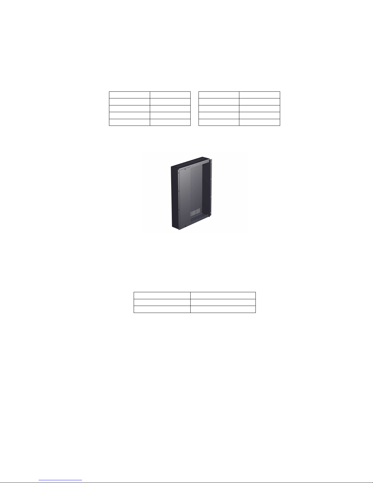
Metal grille (GO 410)
Metal grille (GO 410)Metal grille (GO 410)
Metal grille (GO 410)
A metal grille (pictured below) can be attached to the front of the loudspeaker to protect the drivers. It simply
clips into the grooves on the long sides of the cabinet. It is damped to avoid rattles and has been designed for
acoustic transparency. The grille is available in black and silver.
Page 20
Klein + Hummel O 410 Operating Manual
English Page 16 Version 03
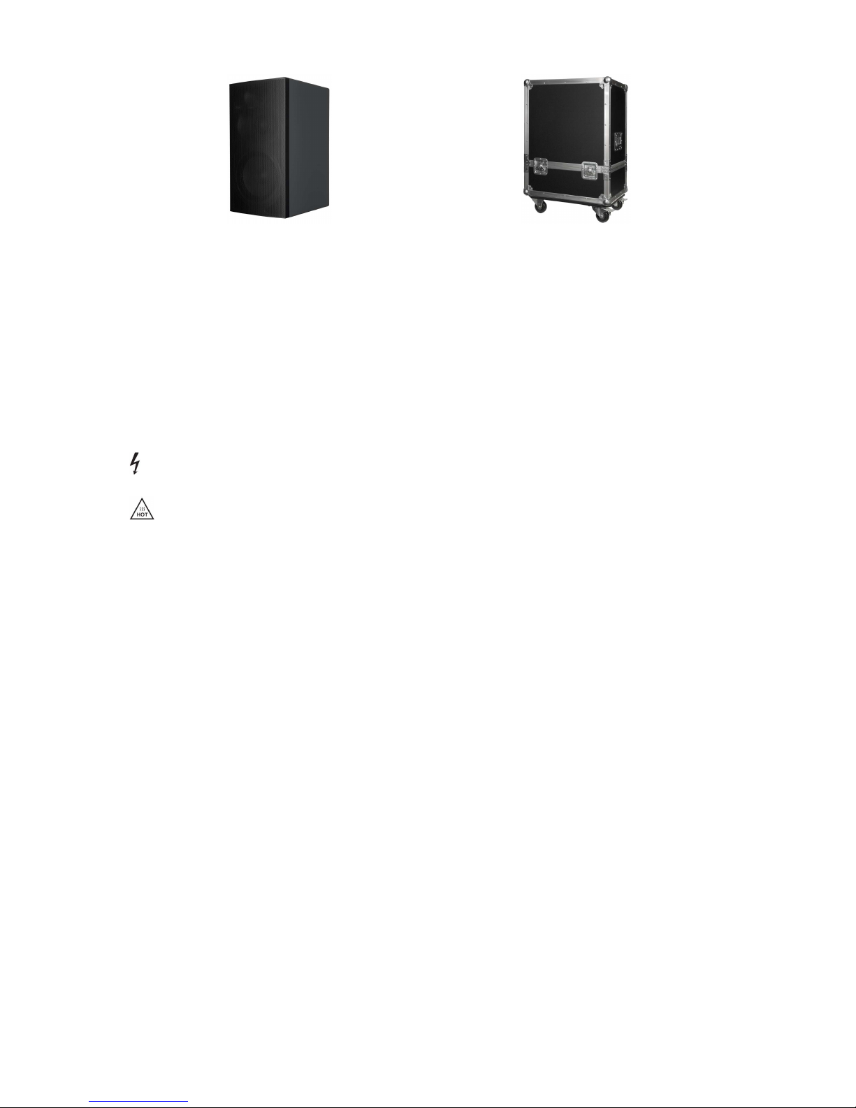
Flight case (FO 410)
Flight case (FO 410)Flight case (FO 410)
Flight case (FO 410)
As the original packing is primarily designed to get the loudspeaker from the factory to the end user, it is highly
recommended that a flight case (pictured above) is used if the loudspeaker is regularly moved between locations.
One O 410 can be packed in each flight case.
Safety and Warnings
Safety and WarningsSafety and Warnings
Safety and Warnings
In addition to specific warnings throughout this document, please observe these additional general instructions.
The term “loudspeaker” includes the case when the electronics of an active loudspeaker is installed into a Remote
Electronics Kit, or when it is still located in the back of the cabinet.
This symbol means that a high voltage is to found nearby. Take appropriate precautions to avoid electric
shocks.
This symbol means that hot parts of the product may be found nearby. Take appropriate precautions to
avoid burns.
General
GeneralGeneral
General
• Keep these instructions in a safe place for future reference.
• Failure to follow the safety and warning instructions contained in this document voids the warranty.
• This product should be used for the intention for which it was designed and as described in this document.
Environment
EnvironmentEnvironment
Environment
• Ensure that the room in which you use this product is wired in accordance with the local electrical code and
checked by a qualified inspector.
• A correctly earthed mains power connection should always be used.
• If access to the interior electronics is required, disconnect it from the mains power and allow electrical energy
storage devices, such as capacitors and transformers, to discharge.
• Other electronic products may generate sufficient heat to require ventilation.
• Do not block or cover heatsinks, fans, or vents.
• Unless otherwise stated, this product is designed to be used indoors only.
• Do not expose this product to water, any other liquids, moisture, or naked flames.
• Do not install this product into hot, humid, or excessively dusty locations, or into direct sunlight.
• Avoid installing this product into locations where it will experience externally generated vibrations or heat
(e.g. radiators).
• If the product is moved from a cold environment into a warm one (such as from a vehicle into a building), it is
possible that condensation will form. Please allow the product sufficient time for acclimatization to room
temperature before using.
• Wherever an amplifier is located, a free flow of air should be maintained by leaving a gap of at least 5 cm
(2”) around it. A flush mounted cabinet with the electronics panel still installed should be well-ventilated to
avoid heat build-up and possible risk of fire.
Use
UseUse
Use
• The equipment should be mounted by a suitably qualified professional in accordance with local, national, and
international regulations and standards.
• Falling equipment can damage itself, people, and other objects, so do not place this unit on any unstable
platform, cart, trolley, stand, table, or mounting hardware.
• Do not use accessories and options with this product that are not approved by Klein + Hummel.
Page 21

Klein + Hummel O 410 Operating Manual
English Page 17 Version 03
• Mounting hardware must be attached to the appropriate hardware and attachment points rated and
intended for such use.
• Ensure that the operating voltage of this product matches that of the local mains voltage.
• Use the power cable that came with this product as this has been manufactured to international safety
standards. If it has been damaged obtain a similarly certified and specified mains power cable.
• This product should be unplugged from the mains power and the signal sources if is not to be used for an
extended period of time, or during lightening storms.
• The power switch on this product should be set to off before applying mains power via the mains power
cable.
• Some parts of this product, particularly power amplifier components, can become hot to the touch. Do not
touch these parts until they have cooled down.
• Never touch the loudspeaker’s drivers.
• Loudspeakers are often capable of producing a sound pressure level in excess of 85 dB. This may cause
permanent hearing damage so user caution is recommended. Noise exposure is a function of SPL and time, so
observe local regulations when listening at high levels for a long time. Hearing protection may be required.
Servicing
ServicingServicing
Servicing
• Repairs, maintenance, or other servicing of this product when its interior compartment is exposed should
only be performed by Klein + Hummel authorized service engineers familiar with the equipment and risks
involved in handling electronics.
• Servicing may be required in the event of exposure to unfavorable environmental conditions, such as liquids,
excessive heat, or a lightning strike.
• Amplifier outputs may carry high voltages so take appropriate precautions, for example, connect the cables
before powering up.
• When replacing a fuse, ensure that a brand new fuse is used. It must be exactly the same type, value, and
voltage as the original, as stated in the product’s technical specifications or on the circuit board.
Maintenance and Servicing
Maintenance and ServicingMaintenance and Servicing
Maintenance and Servicing
• There are no user serviceable parts inside the standard version of this product. Repairs should only be
undertaken by Klein + Hummel certified service engineer.
• Options and accessories are fitted at the user’s own risk.
• Products may be cleaned using a non-abrasive cloth lightly damped with water. Disconnect the mains power
cable when cleaning to avoid risk of electric shock. Do not use alcohol-based cleaners.
• The electronics should only be opened by non-“Klein + Hummel certified service engineer” for the installation
of user installable options as described in the product’s operating manual. The mains power cable should be
disconnected whenever the electronics panel is opened.
• If the main fuse blows, the product should be checked by a Klein + Hummel certified service engineer.
Guarantee
GuaranteeGuarantee
Guarantee
This product comes with a guarantee, a copy of which is enclosed with this product.
Recycling
RecyclingRecycling
Recycling
Attention to product quality in the design phase ensures, firstly, that products have a long life and that, secondly,
all parts of a product may be reused or recycled at the end of that life. An extensive product servicing network
ensures that products can be repaired in the event of the premature failure of a part, or as a way to prolong the
life of a product that would otherwise be considered a candidate for landfill. Eventually there comes a time when
a product is considered beyond repair (for economic reasons or lack of parts), so the parts must be disposed of in
a suitable manner. The disposal should conform to local environmental regulations and be conducted in an
authorized recycling facility.
Loudspeakers and electronic products consist of some or all of these components:
Page 22

Klein + Hummel O 410 Operating Manual
English Page 18 Version 03
Item
ItemItem
Item Material
MaterialMaterial
Material Recycling
RecyclingRecycling
Recycling Instructions
Instructions Instructions
Instructions
Loudspeaker Cabinets Wood (MDF), steel, aluminum,
polyurethane or a combination
Separate materials then recycle
Drivers Aluminum, copper, paper and plastics Separate materials then recycle
Damping Materials Sheep wool Compost
Electronics Panel Aluminum Remove electronics and recycle
Electronics Various Recycle in an approved recycling facility
Remote Electronics Kits Steel and some electronics Separate materials then recycle
Cables and Connectors Metals and/or plastic Reuse or recycle
Packing Material Cardboard, wood and/or plastics Separate materials then recycle
User Manuals and Sales
Literature
Paper and cardboard Recycle
EC Declaration of Conformity
EC Declaration of ConformityEC Declaration of Conformity
EC Declaration of Conformity
This equipment is in compliance with the essential requirements and other relevant provisions of Directives
89/336/EC and 73/23/EC. The declaration is available on the internet site at www.klein-hummel.com. Before
putting the device into operation, please observe any respective country-specific regulations.
For loudspeakers fitted
For loudspeakers fitted For loudspeakers fitted
For loudspeakers fitted with digital inputs: Compliance to FCC Rules
with digital inputs: Compliance to FCC Ruleswith digital inputs: Compliance to FCC Rules
with digital inputs: Compliance to FCC Rules
This device complies with part 15 of the FCC Rules and with RSS-210 of Industry Canada. Operation is subject to
the following two conditions:
• This device may not cause harmful interference, and
• This device must accept any interference received, including interference that may cause undesired operation.
This equipment has been tested and found to comply with the limits for a Class B digital device, pursuant to part
15 of the FCC Rules. These limits are designed to provide reasonable protection against harmful interference in a
residential installation. This equipment generates, uses and can radiate radio frequency energy and, if not
installed and used in accordance with the instructions, may cause harmful interference to radio communications.
However, there is no guarantee that interference will not occur in a particular installation. If this equipment does
cause harmful interference to radio or television reception, which can be determined by turning the equipment
off and on, the user is encouraged to try to correct the interference by one or more of the following measures:
• Reorient or relocate the receiving antenna.
• Increase the separation between the equipment and receiver.
• Connect the equipment into an outlet on a circuit different from that to which the receiver is connected.
• Consult the dealer or an experienced radio/TV technician for help.
This class B digital apparatus complies with the Canadian ICES-003
Changes or modifications to this equipment not expressly approved by Klein + Hummel may void the FCC
authorization to operate this equipment.
Page 23
Klein + Hummel Manuel Utilisateur O 410
Française Page 23 Version 03
Introduction
IntroductionIntroduction
Introduction
Merci d’avoir acheté une enceinte Klein + Hummel. Son guide d’ondes de type Mathematically Modeled
Dispersion™ (MMD™), ses réglages acoustiques d’une grande souplesse, ses différentes options d’entrée et la
gamme étendue d’accessoires de montage et de fixation permettent de l’utiliser dans des conditions très
diverses, sur n’importe quel type de source sonore, dans des emplacements très différents. Elle utilise les
technologies et composants acoustiques et électriques de dernière génération, afin d’assurer la reproduction
sonore la plus précise possible. Les produits Klein + Hummel sont conçus pour durer – nous vous souhaitons donc
de nombreuses années d’utilisation de ce produit.
Selon leurs dimensions, les enceintes 3 voies Klein + Hummel vont du moniteur de proximité aux grosses écoutes.
Elles s’utilisent en musique, en broadcast ou en postproduction pour l’enregistrement, le mixage ou le mastering.
Vous pouvez les placer dans le local d’écoute lui-même, ou les encastrer dans un mur, et les mélanger à votre
guise au sein d’un système d’écoute multicanal.
Avant de lire le reste de ce manuel utilisateur, observez les instructions de sécurité et les avertissements qui se
trouvent dans les dernières pages.
Contenu du carton
Contenu du cartonContenu du carton
Contenu du carton
Le carton d’emballage contient :
• Ce manuel d’utilisation
• La garantie produit
• L’enceinte elle-même
• Trois câbles secteur (Euro, UK et USA)
• Un tournevis pour régler les trim et basculer les sélecteurs
Les câbles audio ne sont pas livrés. La liste des options et accessoires se trouve à la fin de ce manuel utilisateur.
Applications habituelles et distances d’écoute
Applications habituelles et distances d’écouteApplications habituelles et distances d’écoute
Applications habituelles et distances d’écoute
Dans le cadre de l’application habituelle de l’enceinte (écoute “mid-field”, écoute moyenne), voici les distances
d’écoute minimale, recommandée et maximale :
Distances
DistancesDistances
Distances
Produit
ProduitProduit
Produit Application habituelle
Application habituelleApplication habituelle
Application habituelle Minimale
MinimaleMinimale
Minimale Recommandée
RecommandéeRecommandée
Recommandée
Maximale
MaximaleMaximale
Maximale
O 410 Écoute moyenne “Mid-field” 1,5 m 2,5 m 8 m
Dans le cadre de systèmes d’écoute multicanal, l’idéal serait d’utiliser des enceintes identiques sur tous les
canaux. Toutefois, comme le plus souvent, les canaux arrière contiennent moins de graves et leur niveau est
inférieur à celui des enceintes avant, les enceintes arrière peuvent être d’un modèle inférieur – voir le tableau cidessous pour plus de détails. L’enceinte centrale doit toujours être identique aux enceintes gauche et droite. Le
caisson de graves doit être de performances suffisantes par rapport au niveau des enceintes – pour plus de
détails, reportez-vous au manuel utilisateur du caisson de graves.
Avant
AvantAvant
Avant Arrière (idéal)
Arrière (idéal)Arrière (idéal)
Arrière (idéal) Arrière (petites)
Arrière (petites)Arrière (petites)
Arrière (petites) Caisson(s) de graves
Caisson(s) de gravesCaisson(s) de graves
Caisson(s) de graves
O 410 O 410 O 300, O 300 D Voir le manuel utilisateur du caisson
Synoptique
SynoptiqueSynoptique
Synoptique
Voici un synoptique de l’enceinte trois voies :
Page 24

Klein + Hummel Manuel Utilisateur O 410
Française Page 24 Version 03
Pour plus d’informations à propos des fréquences du filtre, de la puissance des amplificateurs et du type des
transducteurs, veuillez vous référer à la section des caractéristiques détaillées du produit. Dans une O 410, le
potentiomètre Low Mid / Mid est un potentiomètre Mid. Comme l’option entrées numériques est installée par
l’utilisateur, il n’existe pas de version “D” de la O 410.
Photo du panneau arrière
Photo du panneau arrièrePhoto du panneau arrière
Photo du panneau arrière
Panneau arrière de l’O 410
Panneau arrière de l’O 410Panneau arrière de l’O 410
Panneau arrière de l’O 410
Page 25

Klein + Hummel Manuel Utilisateur O 410
Française Page 25 Version 03
Étage d’entrée
Étage d’entréeÉtage d’entrée
Étage d’entrée
L’étage d’entrée
étage d’entréeétage d’entrée
étage d’entrée standard
standard standard
standard utilise un connecteur femelle XLR (impédance d’entrée : 14 kohms) – la symétrie est
électronique.
Point
PointPoint
Point Signal
SignalSignal
Signal
1 Masse Audio
2 Point chaud (+)
3 Point froid (-)
Si vous entendez un bourdonnement ou un grésillement en provenance de l’enceinte, vérifiez si elle n’en est pas
elle-même la source, en débranchant le câble d’entrée audio. Si le bruit disparaît, l’enceinte n’est pas en cause – le
parasite provient du câblage lui-même ou de la source de signal. Il existe plusieurs méthodes pour augmenter
l’immunité de l’enceinte aux bruits de fond externes :
• Utilise le sélecteur de levage de masse
le sélecteur de levage de massele sélecteur de levage de masse
le sélecteur de levage de masse pour déconnecter la masse audio, point 1 du connecteur XLR d’entrée
analogique, du châssis de l’électronique. Pour des raisons de sécurité, le châssis de l’électronique est toujours
relié à la terre (via le cordon secteur).
• Intégrez à l’enceinte un étage d’entrée à symétrie par transformateur (optionnel)
étage d’entrée à symétrie par transformateur (optionnel)étage d’entrée à symétrie par transformateur (optionnel)
étage d’entrée à symétrie par transformateur (optionnel). Cette solution est
particulièrement efficace lorsqu’elle est combinée au levage de masse.
• Si vous utilisez des câbles asymétriques, câblez-les de façon spécifique – voir schéma ci-dessous.
Déconnectez le blindage du corps du connecteur RCA si le bourdonnement ou le grésillement persiste, et/ou
levez la masse en entrée de l’enceinte.
Vous pouvez également intégrer un étage d’entrée numérique 24
étage d’entrée numérique 24étage d’entrée numérique 24
étage d’entrée numérique 24 bits, 192
bits, 192bits, 192
bits, 192 kHz
kHzkHz
kHz. Il est pourvu d’entrées sur XLR et
BNC, et offre une sortie BNC. Il est possible de connecter simultanément des signaux d’entrée analogiques et
numériques – le sélecteur permet de choisir l’entrée désirée.
Réglages acoustiques
Réglages acoustiquesRéglages acoustiques
Réglages acoustiques
Les réglages acoustiques sont des filtres analogiques d’ordre assez bas, conçus pour compenser certains des
problèmes acoustiques fréquemment rencontrés dans des environnements d’écoute courants. Selon le modèle
d’enceinte, vous trouverez un potentiomètre Low Mid ou Mid. Les autres potentiomètres sont communs à toutes
les enceintes 3 voies.
Les enceintes Klein + Hummel sont conçues pour présenter une courbe de réponse plane en chambre sourde
lorsque tous les potentiomètres acoustiques se trouvent en position 0 dB. Dès qu’une enceinte se trouve dans un
environnement d’écoute “réel”, sa courbe de réponse change : il faut donc la corriger afin de rétablir une courbe
de réponse plane, par l’intermédiaire des potentiomètres de réglage acoustique. Les valeurs de réglage varieront
selon l’emplacement de l’enceinte, et différeront d’un emplacement à un autre, dans un même local, pour une
même enceinte. Si le local présente une bonne symétrie, les paires d’enceintes gauche/droite (avant ou arrière)
demanderont probablement les mêmes valeurs de réglage acoustique. Vous trouverez quelques valeurs
suggérées après la description des différents potentiomètres :
Le potentiomètre bass
bassbass
bass sert à compenser l’accentuation dans le grave occasionnée naturellement par la présence,
à proximité de l’enceinte, de grandes surfaces dures (mur, plafond, sol…). Quatre valeurs d’atténuation sont
disponibles : 0 / -2,5 / -5 et -7,5 dB.
Page 26
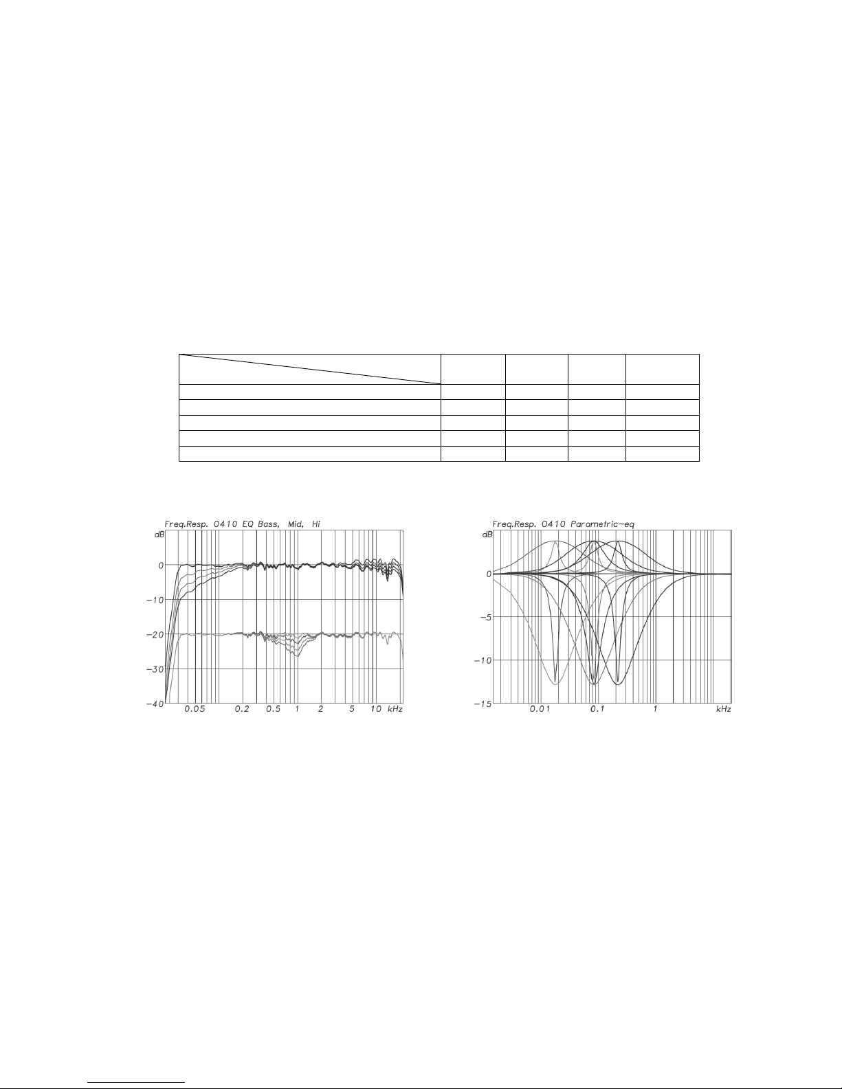
Klein + Hummel Manuel Utilisateur O 410
Française Page 26 Version 03
Le potentiomètre mid
midmid
mid (O 410) sert à compenser les réflexions de premier ordre marquées (sur le sol, le plafond,
les murs latéraux) qui peuvent provoquer une certaine agressivité dans le médium. Cet effet peut aussi être
provoqué par un temps de réverbération trop élevé dans le registre médium – qu’il faut donc compenser. Quatre
valeurs sont disponibles : 0 / -1,5 / -3 et -4,5 dB.
Le potentiomètre treble
trebletreble
treble agit sur le niveau de sortie du tweeter, et peut servir à compenser un amortissement des
aigus trop marqué (ou pas assez) dans le local d’écoute. Il est souvent réglé en fonction des goûts personnels de
l’ingénieur du son, alors que dans un environnement acoustique bien contrôlé, il n’y a aucune raison de le régler
sur autre chose que 0 dB. Quatre valeurs sont disponibles : +1 / 0 / -1 et -2 dB.
L’égaliseur parametric
parametricparametric
parametric est un simple étage de correction paramétrique (PEQ), permettant d’intervenir sur le gain
(de +4 à -12 dB), la fréquence d’intervention (de 20 à 200 Hz) et le Q (de 1 à 8), de façon à compenser des nonlinéarités se manifestant en dessous de 200 Hz. Ces non-linéarités peuvent provenir d’accentuations naturelles
provoquées par des interférences constructives, ou par des modes propres acoustiques marqués. Le sélecteur
Bypass permet de désactiver cet égaliseur paramétrique.
Pour régler ces potentiomètres de la façon la plus appropriée en fonction de l’emplacement des enceintes, il est
conseille d’utiliser un système de mesure acoustique – notamment pour ajuster l’égaliseur paramétrique. En
l’absence de dispositif de mesure, nous vous recommandons de partir des valeurs suivantes :
Réglage acoustique
Réglage acoustiqueRéglage acoustique
Réglage acoustique
Emplacement enceinte
Emplacement enceinteEmplacement enceinte
Emplacement enceinte
Bass
BassBass
Bass Mid
MidMid
Mid
O 410
Treble
TrebleTreble
Treble Parametric
ParametricParametric
Parametric
Dans un coin -7,5 dB - - ***
******
***
Près d’ (ou encastré dans) un mur dur -5 dB - - Près d’ (ou encastré dans) un mur ‘souple’ -2,5 dB - - Salle non traitée, champ libre -2,5 dB -1,5 dB -1 dB ***
******
***
Salle bien traitée, champ libre - - - -
***
******
*** Indique qu’il faudra probablement utiliser l’égaliseur paramétrique. Son paramétrage dépend de la situation,
aucune recommandation standard n’est possible.
O 410 : Ac
O 410 : AcO 410 : Ac
O 410 : Action des potentiomètres
tion des potentiomètrestion des potentiomètres
tion des potentiomètres O 410 : Action de l’égaliseur paramétrique
O 410 : Action de l’égaliseur paramétriqueO 410 : Action de l’égaliseur paramétrique
O 410 : Action de l’égaliseur paramétrique
Bass, Midrange et Treble
Bass, Midrange et TrebleBass, Midrange et Treble
Bass, Midrange et Treble
Les réglages de niveau d’entrée
d’entrée d’entrée
d’entrée et de sortie
sortie sortie
sortie s’effectuent via un potentiomètre gradué avec précision, repéré
“Input Gain
Input GainInput Gain
Input Gain”, et d’un potentiomètre “Output Level
Output LevelOutput Level
Output Level” d’action plus grossière. Ils permettent d’adapter l’enceinte
aux niveaux de fonctionnement d’appareils très divers, tout en maintenant le niveau de pression acoustique
désiré. Comme pour tout maillon d’une chaîne audio, il est préférable d’utiliser le gain le plus bas possible pour
l’application, pour éviter d’amplifier le bruit de fond provenant des appareils sources situés en amont. Pour
vérifier cet aspect, il suffit de débrancher le câble audio arrivant à l’enceinte : si le niveau de bruit de fond
descend de façon notable, c’est que le souffle provient de la source, et non de l’enceinte elle-même. Les valeurs
par défaut sont “0 dB” et “100 dB SPL à 1 m”. Autrement dit, vous obtenez un niveau de pression sonore de
100 dB SPL à 1 mètre pour un signal d’entrée d’un niveau électrique de 0 dBu (soit 0,775 Volt). La sensibilité
maximale (niveau de pression sonore le plus élevé pour une tension d’entrée donnée) est obtenue en position
“6 dB” et “114 dB SPL à 1 m”, et la sensibilité la plus basse, pour “-9 dB” et “100 dB SPL à 1 m”.
Page 27

Klein + Hummel Manuel Utilisateur O 410
Française Page 27 Version 03
Niveau de pression sonore [dB SPL] émis par l’enceinte
Niveau de pression sonore [dB SPL] émis par l’enceinteNiveau de pression sonore [dB SPL] émis par l’enceinte
Niveau de pression sonore [dB SPL] émis par l’enceinte
à 1 mètre, pour un niveau de signal d’entrée de 0 dBu
à 1 mètre, pour un niveau de signal d’entrée de 0 dBuà 1 mètre, pour un niveau de signal d’entrée de 0 dBu
à 1 mètre, pour un niveau de signal d’entrée de 0 dBu
Position du
Position du Position du
Position du
potentiomètre
potentiomètre potentiomètre
potentiomètre
Sensitivity [dB]
Sensitivity [dB]Sensitivity [dB]
Sensitivity [dB]
Sélecteur
SélecteurSélecteur
Sélecteur
Output Level = “100 dB”
Output Level = “100 dB”Output Level = “100 dB”
Output Level = “100 dB”
Sélecteur
SélecteurSélecteur
Sélecteur
Output Level = “114 dB”
Output Level = “114 dB”Output Level = “114 dB”
Output Level = “114 dB”
-9 dB 91 105
-8 dB 92 106
-7 dB 93 107
-6 dB 94 108
-5 dB 95 109
-4 dB 96 110
-3 dB 97 111
-2 dB 98 112
-1 dB 99 113
0 dB 100 (réglage par défaut)
114
1 dB 101 115
2 dB 102 116
3 dB 103 117
4 dB 104 118
5 dB 105 119
6 dB 106 120
Voici quelques exemples de calcul du niveau de pression sonore obtenu :
Niveau de signal d’entrée [dBu] 0 (0,775 V) +4 (1,23 V) +6 (1,55 V) +16 (4,89 V)
Réglage de gain d’entrée [dB] 0 0 0 0
Réglage de niveau de sortie [dB SPL] 100 100 100 100
Niveau de pression sonore émis par l’enceinte
[dB SPL à 1 mètre] 100 104 106 116
En Europe, le niveau analogique 0 dBu correspond à -18 dB FS (standard UER R68). Aux États-Unis, le niveau
analogique +4 dBu correspond à -20 dB FS (standard SMPTE RP155). Ces valeurs en dBu correspondent à un
niveau de pression sonore de 85 dB SPL, relevé à l’emplacement d’écoute. Dans les milieux broadcast, on adopte
souvent un niveau de référence de 79 dB SPL à l’emplacement d’écoute. Les écoutes “de proximité” (near field)
peuvent se trouver à 1 mètre de l’emplacement d’écoute, tandis que dans un auditorium de mixage certifié Dolby,
les enceintes doivent se trouver à au moins 5 mètres de l’emplacement d’écoute. Dans les exemples ci-dessous,
nous supposons que l’ingénieur du son se trouve au centre du local d’écoute, et que le champ sonore décroît en
niveau selon 20 log10 (r), même si ce n’est pas toujours le cas. Veuillez noter qu’une atténuation supplémentaire
au niveau de la source (-6 ou -10 dB) est souvent nécessaire dans le cadre d’une écoute de proximité calibrée en
niveau, mais cette fonctionnalité est souvent disponible dans la console elle-même.
Niveau de signal d’entrée [dBu] 0 (0,775 V) +4 (1,23 V)
Réglage de gain d’entrée [dB] -1 -5
Réglage de niveau de sortie [dB SPL] 100 100
Distance d’écoute [m] (atténuation
correspondante, en dB)
5 m (-14 dB) 5 m (-14 dB)
Niveau de pression sonore émis par l’enceinte
[dB SPL à 1 mètre] 85 85
Niveau d’entrée maximal avant écrêtage +17 dBu +17 dBu
Le niveau d’entrée maximal admissible par l’étage d’entrée est d’environ +19 dBu (soit 6,9 Volts). Pour éviter
l’écrêtage à l’entrée, augmentez la valeur de sensibilité de l’enceinte, jusqu’à 6 dB. Le niveau de pression sonore
maximal générable par l’enceinte est limité par le dispositif de protection intégré. De façon générale, les grosses
enceintes peuvent soutenir un niveau sonore plus élevé, et pendant plus longtemps, que des enceintes plus
petites.
Autres commandes
Autres commandesAutres commandes
Autres commandes
Le display dimmer
display dimmerdisplay dimmer
display dimmer sert à atténuer la luminosité du témoin lorsque l’enceinte est utilisée dans des conditions
d’éclairage faible. Vous pouvez aussi éteindre le témoin si vous utilisez l’enceinte derrière un écran transparent
acoustiquement. Quatre valeurs sont disponibles : 100, 66, 33 et 0 %.
Page 28

Klein + Hummel Manuel Utilisateur O 410
Française Page 28 Version 03
L’interrupteur Power On/Off
Power On/OffPower On/Off
Power On/Off sert à allumer/à éteindre complètement l’enceinte. L’alimentation de l’enceinte
intègre un circuit de temporisation permettant de réduire l’appel de courant lors de la mise sous tension, ce qui
évite de faire fondre les fusibles secteur.
Le sélecteur de tension
sélecteur de tensionsélecteur de tension
sélecteur de tension offre les positions 230, 120 et 100 V. Réglez-le sur la valeur appropriée AVANT de
brancher l’enceinte. Le fusible interne approprié est alors sélectionné automatiquement. La tension effectivement
appliquée devrait être comprise entre -15% et +10% de la valeur sélectionnée.
Le connecteur 12 V trigger
12 V trigger12 V trigger
12 V trigger permet d’allumer/éteindre l’enceinte à distance, sans utiliser l’interrupteur secteur. Il
est très utile dans un grand local, lorsque tout l’équipement est allumé via le même interrupteur. Cette possibilité
peut être utile dans le cas de figure où toute l’installation électrique du local d’écoute est régie par un seul
interrupteur/disjoncteur. Vous pouvez retarder la mise sous tension de l’appareil en utilisant un circuit basse
tension assez simple, de façon à étaler dans le temps la demande de courant lors de l’allumage. Notez que ce
connecteur allume/éteint l’électronique de l’enceinte de façon globale (ce n’est pas un simple circuit de Mute) : la
temporisation à l’allumage fait intervenir les mêmes relais pour éviter les bruits parasites de mise sous tension de
l’électronique. Tout se passe comme si vous allumiez ou éteigniez l’enceinte via son interrupteur secteur. Il existe
deux modes de fonctionnement, choisis via un sélecteur interne (voir photo ci après) :
Mode Re
Mode ReMode Re
Mode Remote Power
mote Power mote Power
mote Power Position du sélecteur
Position du sélecteurPosition du sélecteur
Position du sélecteur Fonction
FonctionFonction
Fonction
“12 V TURNS OFF” Côté opposé à la
plaque arrière
Appliquer une tension de 12 Volts entre les contacts du connecteur Remote Control ÉTEINT le
caisson de graves.
Supprimer la tension de 12 Volts entre les contacts du connecteur Remote Control ALLUME le
caisson de graves.
“12 V TURNS ON” Côté plaque arrière Appliquer une tension de 12 Volts entre les contacts du connecteur Remote Control ALLUME
le caisson de graves.
Supprimer la tension de 12 Volts entre les contacts du connecteur Remote Control ÉTEINT le
caisson de graves.
Le mode par défaut, réglé en usine, est “12 V TURNS OFF”. Dans les deux modes, que la tension soit ou non
appliquée aux contacts du connecteur, placer l’interrupteur secteur sur “OFF” éteint le caisson de graves.
Pour faire passer le mode Remote Power sur “12V TURNS ON” :
• Éteignez l’enceinte, déconnectez le cordon secteur et les câbles de signal.
• Ouvrez le panneau contenant l’électronique (qu’il soit monté sur le coffret de l’enceinte ou déporté à
distance).
• Repérez le gros sélecteur sur la carte d’alimentation secteur principale, et placez-le côté plaque arrière.
• Refermez le panneau contenant l’électronique, reconnectez le cordon secteur et les câbles de signal.
• Allumez le caisson de graves, appliquez une tension de 12 Volts entre les contacts du connecteur Remote
Control, et vérifiez que les témoins appropriés sont allumés.
Crossover (filtre actif)
Crossover (filtre actif)Crossover (filtre actif)
Crossover (filtre actif)
Basé sur des filtres du 4è ordre, le crossover intégré à l’O 410 divise le signal d’entrée en trois bandes de
fréquences, afin de les reproduire par des transducteurs séparés, les plus appropriés. L’alignement temporel
assure que le son généré par chaque transducteur est émis en même temps que les autres. De plus, un système
de protection très efficace évite d’abîmer l’enceinte même si vous lui envoyez un signal d’entrée de niveau très
élevé. Le témoin rouge “PROTECT” s’allume lors de l’activation de ce dispositif de protection. Dans ce cas de
Page 29

Klein + Hummel Manuel Utilisateur O 410
Française Page 29 Version 03
figure, réduisez le niveau du signal d’entrée. Si ce phénomène survient régulièrement, utilisez une enceinte plus
grosse, autorisant un niveau SPL plus élevé, ou ajoutez un caisson de graves, afin de soulager l’enceinte de la
reproduction des graves à haut niveau, gourmande en énergie. Le dispositif de protection allie des limiteurs
thermiques et de crête pour les amplificateurs, une modélisation thermique des transducteurs, et un limiteur
d’excursion pour les transducteurs.
Le dispositif de protection n’est pas un compresseur, il est conçu pour protéger les enceintes de tout dommage –
un témoin lumineux rouge indique son activation à l’utilisateur. Il est inefficace si vous poussez trop loin
l’enceinte pendant trop longtemps. Si le témoin Protect est allumé, ne continuez pas à utiliser l’enceinte à haut
niveau comme si de rien n’était – vous allongerez sa durée de vie.
La section crossover intègre également des atténuateurs de réglage cachés, afin d’éviter toute modification
“accidentelle”. Ils ne doivent être ajustés que par un technicien qualifié disposant d’un équipement de mesure
spécialisé. Si vous remplacez un composant critique pour la qualité sonore – par exemple, un bommer –, il faut,
dans l’idéal, recalibrer l’enceinte dans un S.A.V. Klein + Hummel équipé d’une chambre sourde.
Amplificateurs
AmplificateursAmplificateurs
Amplificateurs
L’enceinte O 410 utilise des amplificateurs travaillant en Classe AB : dans le cas d’enceintes de studio de type ‘full
range’, les performances ainsi obtenues restent supérieures à toute autre solution. Les distorsions harmonique et
par intermodulation, ainsi que le bruit de fond, sont toujours très bas dans des amplificateurs de Classe AB bien
conçus. La dissipation de chaleur est réduite, grâce à l’utilisation de techniques de Classe H sur chaque canal
d’amplification, afin de réduire la tension d’alimentation de l’amplificateur lorsque le signal d’entrée est bas. Ce
qui n’empêche pas de laisser un certain espace (5 cm au minimum) autour du panneau arrière de l’enceinte, qui
renferme son électronique.
L’Accelerated Heat Tunneling™ (AHT™) est une technique conçue pour assurer un refroidissement efficace des
amplificateurs, que l’enceinte soit disposée verticalement ou horizontalement. L’“effet entonnoir ” accélère l’air
frais passant par l’ouverture inférieure du radiateur, et expulse l’air chaud par l’ouverture supérieure du
radiateur. Nous vous recommandons de vérifier tous les six mois que le radiateur de l’amplificateur est libre de
toute poussière ou saletés diverses. Les radiateurs se nettoient sans ouvrir le panneau électronique : il suffit de
les soumettre à un jet d’air comprimé, depuis le côté du panneau électronique, qui traverse le radiateur. Si le
radiateur est sale, le refroidissement s’effectue moins bien, ce qui réduit le niveau SPL maximal produit par
l’enceinte.
Si l’enceinte est encastrée, nous vous recommandons de monter le panneau électronique sur un kit de déport
(Remote Electronics Kit) – voir la section Options et Accessoires. Même si vous ne risquez pas d’endommager les
enceintes, un refroidissement insuffisant conduira à une activation précoce de la protection de l’amplificateur, ce
qui limitera le niveau de sortie maximal autorisé par l’enceinte.
Transducteurs
TransducteursTransducteurs
Transducteurs
Les transducteurs utilisés dans l’O 410 sont les meilleurs disponibles dans leur domaine d’application. Efficacité
élevée, grand débattement, faible distorsion assurent une excellente qualité sonore, même à niveau d’écoute
élevé. Le boomer est chargé par le volume interne du coffret ; les transducteurs de médium et d’aigu possèdent
leurs propres cavités arrière. Tous les transducteurs sont blindés, ce qui autorise l’utilisation de l’enceinte à
proximioté immédiate d’écrans cathodiques ou de disques durs, par exemple. Le volume du coffret et le niveau de
pression sonore maximal de l’enceinte sont donnés dans la section consacrée aux caractéristiques techniques, ci
après.
Guide d’onde MMD™ (Mathematically Modeled Dispersion™ Waveguide) de l’O 410
Guide d’onde MMD™ (Mathematically Modeled Dispersion™ Waveguide) de l’O 410Guide d’onde MMD™ (Mathematically Modeled Dispersion™ Waveguide) de l’O 410
Guide d’onde MMD™ (Mathematically Modeled Dispersion™ Waveguide) de l’O 410
Les transducteurs de médium et d’aigu sont montés dans un guide d’onde de type Mathematically Modeled
Dispersion™. Ce guide d’onde MMD™ est réalisé dans le même matériau, aux excellentes propriétés acoustiques,
que le modèle O 300 : le LRIM™. Il a été modélisé mathématiquement, puis vérifié expérimentalement en chambre
sourde, afin d’assurer une directivité optimale pour les transducteurs de médium et d’aigu. Avantages : une
meilleure charge du transducteur, une diffraction réduite sur les coins, des réflexions atténuées dans le local, une
courbe de réponse plus constante et une région d’écoute idéale (sweetspot) plus étendue. Au final, une distorsion
audio plus réduite et une meilleure qualité sonore subjective. Le guide d’onde MMD™ assure une dispersion sur
80° x 60° ; par conséquent, si vous disposez l’enceinte à l’horizontale, il faut faire pivoter le guide d’onde de 90°,
Page 30

Klein + Hummel Manuel Utilisateur O 410
Française Page 30 Version 03
dans un sens ou dans l’autre, par rapport à sa position d’origine. Ce guide d’onde pivotant permet de placer le
boomer d’un côté ou de l’autre du MMD™. Si vous disposez l’enceinte “tête en bas”, le MMD™ doit aussi se
retrouver à l’envers, afin de maintenir une transition grave/médium optimale. Comme la sérigraphie se retrouve
alors elle aussi à l’envers, veuillez contacter directement K+H en Allemagne, pour commander un adhésif de
remplacement, avec la sérigraphie à l’envers. Quelle que soit l’orientation du coffret, l’axe acoustique doit pointer
vers l’emplacement d’écoute de l’ingénieur du son, ou au centre de la zone d’écoute, à la fois dans le plan
horizontal et dans le plan vertical – voir la section Coffret pour une définition de l’axe acoustique.
Voici comment faire pivoter le MMD™:
• Placez le coffret de l’enceinte sur son panneau arrière, sur une surface plane et pas trop dure, de façon à ce
que les transducteurs soient dirigés vers le haut.
• Dévissez les quatre vis Allen du MMD™, en utilisant un tournevis à tête Allen T4.
• Dégagez doucement le MMD™ du coffret, en évitant de rayer la peinture et d’endommager la bande
d’étanchéité.
• Replacez le MMD™ dans sa nouvelle orientation, puis centrez-le dans la découpe de la face avant.
• Resserrez les quatre vis Allen sur le MMD™, en appliquant un couple de serrage de 3,7 Nm.
• Testez l’étanchéité du coffret en reproduisant à niveau raisonnable (vous devez sentir le déplacement de l’air
par les ports) un signal sinusoïdal de fréquence égale à la fréquence de coupure de l’enceinte dans le grave, à
-3 dB (voir caractéristiques ci après). Écoutez ensuite ce qui se passe sur les bords du MMD et de ses
transducteurs. Si vous entendez une sorte de souffle, l’étanchéité est compromise, il faut remplacer la bande
d’étanchéité.
Coffret
CoffretCoffret
Coffret
Le coffret en bois est peint d’une couleur au standard RAL . Pour faire des retouches, par exemple si la peinture de
l’enceinte a été rayée lors du transport ou de l’utilisation, vous pouvez utiliser un crayon de peinture de la couleur
appropriée. Voici les numéros RAL correspondant aux couleurs standard des coffrets d’enceintes K+H.
Nom de la
Nom de la Nom de la
Nom de la
couleur K+H
couleur K+Hcouleur K+H
couleur K+H
Numéro
Numéro Numéro
Numéro
couleur RAL
couleur RALcouleur RAL
couleur RAL
Anthracite 7021
Argent 9006
Les ports chargent le transducteur, associés au volume du coffret, afin d’étendre sa réponse dans les graves. Ils
ont été conçus de façon à ne pas gêner le passage de l’air, à ne pas créer de turbulences ou toute non-linéarité
susceptible de dégrader la qualité sonore.
L’axe acoustique est une droite normale au panneau avant de l’enceinte acoustique, le long de laquelle était placé
le microphone de mesure lors de la phase d’affinage de la conception du filtre de l’enceinte. Pour obtenir la
meilleure qualité sonore subjective (et aux mesures), il faut placer l’axe acoustique, dans les plans horizontal et
vertical, vers l’emplacement d’écoute ou vers le centre de la zone d’écoute. Dans le cas des enceintes trois voies
Klein + Hummel, l’axe acoustique se situe au point médian séparant le haut-parleur de médium du tweeter.
Page 31

Klein + Hummel Manuel Utilisateur O 410
Française Page 31 Version 03
x
y
Produit
ProduitProduit
Produit Dimension x
Dimension x Dimension x
Dimension x Dimension y
Dimension y Dimension y
Dimension y
O 410 16,5 cm 51 cm
Position de l’axe acoustique de l’O 410
Position de l’axe acoustique de l’O 410Position de l’axe acoustique de l’O 410
Position de l’axe acoustique de l’O 410
Utilisation de l’enceinte
Utilisation de l’enceinteUtilisation de l’enceinte
Utilisation de l’enceinte
Les enceintes de studio Klein + Hummel ne doivent être utilisées qu’en intérieur, dans les conditions ambiantes
suivantes :
• +10° C à +40° C, taux d’hygrométrie relative < 90 %, pas de condensation
Pour le transport ou le stockage, les conditions ambiantes limites sont les suivantes :
• -25° C à +70° C, taux d’hygrométrie relative < 90 % pas de condensation
Avant de connecter le câble secteur, vérifiez que la tension secteur appropriée est sélectionnée sur le panneau
électronique, à l’arrière de l’enceinte (230, 120 ou 100 Volts) et que l’interrupteur se trouve en position Off.
Branchez ensuite le câble du signal audio (analogique, numérique ou les deux si approprié), puis mettez
l’enceinte sous tension. La temporisation impose cinq secondes de silence avant de laisser passer le son sur
l’enceinte – afin d’éviter tout bruit parasite si vous allumez en même temps un appareil situé en amont dans la
chaîne de signal. En revanche, lorsque vous éteignez l’enceinte, le son est coupé immédiatement. Le logo K+H
s’allume, en même temps que l’indicateur vert ou jaune, pour indiquer la présence d’un signal analogique ou
numérique. Si rien ne s’allume, vérifiez la présence de tension secteur, et l’atténuateur d’affichage (vérifiez qu’il
n’est pas réglé sur 0 %).
Pour une application en studio, les enceintes doivent être placées conformément à la recommandation ITU-R
BS.775-1, de façon à assurer une homogénéité de reproduction par rapport à d’autres environnements d’écoute.
Dans le cas d’applications “cinéma”, le standard de configuration du système d’écoute est l’ANSI/SMPTE 202M.
Pour une utilisation domestique, comme les contenus sont mixés dans des cabines conformes ITU, nous vous
recommandons de vous approcher le plus possible de cette configuration, afin d’obtenir une qualité de
reproduction maximale.
Canal
Canal Canal
Canal Angle selon
Angle selonAngle selon
Angle selon
ITU
ITUITU
ITU----R BS.775
R BS.775R BS.775
R BS.775----1
1 1
1
Angle selon
Angle selonAngle selon
Angle selon
AAAANSI/SMPTE 202M
NSI/SMPTE 202MNSI/SMPTE 202M
NSI/SMPTE 202M
Gauche -30° -22,5°
Centre 0° 0°
Droit 30° 22,5°
Surround gauche -110°±10° Série d’enceintes à gauche
Surround droit 110°±10° Série d’enceintes à droite
Dans le cas d’une stéréo à deux canaux, mieux vaut utiliser l’angle ±30°. Il n’existe pour l’instant aucun standard
agréé internationalement en ce qui concerne les formats 6.1 ou 7.1. Toutefois, une pratique répandue consiste à
Page 32

Klein + Hummel Manuel Utilisateur O 410
Française Page 32 Version 03
utiloiser une ou deux enceintes à l’emplacement central arrière d’un système 6.1. Dans le cas d’un système 7.1, il
ets d’usage de placer les enceintes latérales à ±90° et de repousser les enceintes Surround arrière à ±150°.
Pour obtenir la meilleure image stéréophonique, les enceintes devraient être placées de façon symétrique dans un
local aménagé symétriquement, et où les objets sont eux aussi disposés symétriquement. Vous obtenez ainsi la
même réponse de chaque enceinte acoustique à l’emplacement d’écoute, donc une image sonore cohérente.
Mieux vaut atténuer les réflexions sonores arrière revenant à l’emplacement d’écoute, via des surfaces
d’angulation étudiée ou un traitement acoustique. L’axe acoustique de l’enceinte doit pointer vers l’emplacement
d’écoute ou le centre de la zone d’écoute, dans les plans horizontal et vertical.
Les enceintes devraient être disposées sur un cercle, de façon à assurer une arrivée simultanée de l’énergie
sonore aux oreilles de l’auditeur. Si ce n’est pas le cas, il faut insérer des retards électroniques appropriés de façon
à compenser les différences de marche acoustiques.
Si vous n’encastrez pas l’enceinte, nous vous recommandons d’utiliser des pieds spécialisés de bonne qualité et
des accessoires appropriés (voir la section Accessoires et Options).
Les avantages de l’encastrement sont les suivants : diffraction réduite sur les angles du coffret (donc un médium
mieux reproduit), meilleur chargement du boomer (donc une distorsion réduite dans les graves), élimination du
retour de l’onde arrière par réflexion sur le mur (donc une réponse plus régulière dans les graves). Nous
recommandons de confier la coneption du mur d’encastrement à un ingénieur acousticien expérimenté. Les
réglages recommandés des contrôles acoustiques se trouvent dans la section Contrôles Acoustiques, et nous vous
recommandons instammént d’utiliser un kit de déport d’électronique (Remote Electronics Kit), présenté dans la
section Accessoires et Options, afin d’éviter tout problème de dissipation de chaleur et de permettre un réglage
facile des contrôles. Si vous désirez masquer l’enceinte, utilisez un tissu acoustique fin et ouvert. Pour une
meilleure opacité, utilisez deux couches de textile très fin.
Avant d’intervenir sur le Trim des niveaux, commencez par calibrer la réponse de chaque enceinte acoustique :
• Dans le cadre d’applications de studio, la courbe de réponse de chaque enceinte devrait être plate, mesurée à
l’emplacement d’écoute.
• Dans le cadre d’applications cinéma, la courbe de réponse de chaque enceinte doit être conforme à une des
courbes X, en fonction des dimensions du local (voir ANSI/SMPTE 202M).
• Dans le cadre d’applications domestiques, la réponse de chaque enceinte doit être réglée pour obtenir la
meilleure qualité audio subjective. Ce qui ne correspond pas forcément à une courbe de réponse plate, mais
généralement, au fil du temps, on préfère souvent une courbe de réponse chutant légèrement dans les aigus.
La calibration acoustique de niveau s’effectue en utilisant un sonomètre réglé sur la pondération C, avec un
temps d’intégration lent. Reproduisez un signal de bruit rose, large bande, à un niveau électrique de -18 dB FS
(Europe) ou -20 dB FS (USA) lu sur les indicateurs de niveau de la console, et mesurez le niveau de pression
sonore à l’emplacement d’écoute. Ajustez ensuite le niveau de chaque canal, jusqu’à atteindre la valeur désirée :
Application
Application Application
Application Niveau SPL mesuré
Niveau SPL mesuréNiveau SPL mesuré
Niveau SPL mesuré
Cinéma 85 dB(C)
Broadcast 79 dB(C)
Musique Selon l’ingénieur du son
Pour plus d’informations sur l’utilisation et la configuration d’un caisson de graves avec ces enceintes, veuillez
vous référer au manuel utilisateur livré avec le caisson de graves.
Page 33

Klein + Hummel Manuel Utilisateur O 410
Française Page 33 Version 03
Caractéristiques Techniques
Caractéristiques TechniquesCaractéristiques Techniques
Caractéristiques Techniques
Caractéristiques acoustiques
Caractéristiques acoustiquesCaractéristiques acoustiques
Caractéristiques acoustiques
Réponse en fréquence en champ libre, à -3 dB 30 Hz à 24 kHz, ± 3 dB
Réponse en fréquence en champ libre, passe-bande 32 Hz à 20 kHz, ± 2 dB
Niveau de bruit propre
≤25 dB (A) à 10 cm
Niveau de sortie, pour THD < 0,5 % à une distance de 1 m 95 dB SPL (>100 Hz)
Niveau SPL maxi, demi-espace, pour 3% de THD 120.0 dB SPL
Moyenné entre 100 Hz et 6 kHz
Caractéristiques électroniques
Caractéristiques électroniquesCaractéristiques électroniques
Caractéristiques électroniques
Amplificateur boomer, puissance de sortie cont. (crête)* 340 W (400 W)
Amplificateur médium, puissance de sortie cont. (crête)* 160 W (190 W)
Amplificateur tweeter, puissance de sortie cont. (crête)* 180 W (210 W)
Type contrôleur intégré analogique, actif
Fréquences de filtrage 600 Hz/2,2 kHz
Pente des filtres (dB/oct.) 24
Égalisation : Low cut –
Bass 0 / -2,5 / -5 / -7,5 dB
Mid 0 / -1,5 / -3 / -4,5 dB
High +1 / 0 / -1 / -2 dB
Égaliseur paramétrique : Bypassable
Gain +4 à -12 dB
Fréquence 20 à 200 Hz
Q 1 à 8
Réglage de délai Time of Flight –
Circuit de protection Limiteur : low, mid, high
Fréquence de coupure et pente du filtre infrasonique 15 Hz ; 12 dB/oct.
Entrée analogique
Entrée analogiqueEntrée analogique
Entrée analogique
Impédance, symétrie électronique XLR, 13 kohms
Impédance, symétrie par transformateur XLR, 4,7 kohms (optionnelle)
Sensibilité d’entrée -8 dBu / +6 dBu
Atténuateur -9 à + 6 dB
Taux de réjection de mode commun (CMRR) >60 dB à 15 kHz
Entrée/sortie numérique
Entrée/sortie numériqueEntrée/sortie numérique
Entrée/sortie numérique Optionnelle
Format XLR (Format BNC) AES/EBU (AES3id, S/PDIF)
Impédance XLR, symétrique 110 Ohms
Impédance BNC, asymétrique 75 Ohms (entrée et sortie)
Sélecteur d’entrée Analog/Digital A, B, Mono
Convertisseur N/A : résolution, type
16 à 24 bits, ∆Σ
Fréquence d’échantillonnage 20 à 216 kHz (SRC)
Indicateurs, alimentatio
Indicateurs, alimentatioIndicateurs, alimentatio
Indicateurs, alimentation secteur
n secteurn secteur
n secteur
Afficheurs et indicateurs : sous tension Logo K + H logo “rouge”
limiteur/écrêtage (clip) LED rouge
Indication
Présence signal analogique (vert),
Erreur signal numérique (jaune)
Tension secteur 230, 120, 100 V AC
Consommation (veille) 36 VA
Consommation (puissance nominale) 1300 VA
Caractéristiques mécaniques
Caractéristiques mécaniquesCaractéristiques mécaniques
Caractéristiques mécaniques
Dimensions (L x H x P) 330 x 645 x 444 mm
[en pouces] 25 3/8” x 13” x 17 1/2”
Volume interne net 42 liters
Poids 36.0 kg (79.2 lb)
Transducteurs Magnetically shielded
Boomer 10", 250 mm
Médium 3", 76 mm
Tweeter 1", 25 mm
Points de montage Inserts filetés à l’arrière
Dispositif de montage livré –
Finition surface coffret Peinte
Couleur : standard Anthracite ou argent
Couleur : personnalisée, option payante –
Protection baffle et transducteurs Grille métallique optionnelle
*THD+N < 0,1 % avec limiteur désactivé
Page 34

Klein + Hummel Manuel Utilisateur O 410
Française Page 34 Version 03
Mesures acoustiques
Mesures acoustiquesMesures acoustiques
Mesures acoustiques
Vous trouverez ci après une série de mesures acoustiques, effectuées en chambre sourde, à 1 m de l’enceinte. Ces
courbes sont disponibles, en version couleurs, sur le site Web www.klein-hummel.com, à la page produit
appropriée.
O 410, réponse en champ libre
O 410, réponse en champ libreO 410, réponse en champ libre
O 410, réponse en champ libre O 410, temps de propagation de groupe
O 410, temps de propagation de groupeO 410, temps de propagation de groupe
O 410, temps de propagation de groupe
125 250 500 10 00 2000 4000 8000 16000
-90ø
-60ø
-30ø
0ø
30ø
60ø
90ø
Grad
3-6
0-3
-3-0
-6--3
-9--6
-12--9
-15--12
-18--15
-21--18
125 250 500 1000 2000 4000 8000 16000
-90ø
-60ø
-30ø
0ø
30ø
60ø
90ø
Grad
3-6
0-3
-3-0
-6--3
-9--6
-12--9
-15--12
-18--15
-21--18
O 410, directivité horizontale
O 410, directivité horizontaleO 410, directivité horizontale
O 410, directivité horizontale O 410, directivité verticale
O 410, directivité verticaleO 410, directivité verticale
O 410, directivité verticale
O 410,
O 410,O 410,
O 410, distorsion harmonique à 95 dB SPL
distorsion harmonique à 95 dB SPL distorsion harmonique à 95 dB SPL
distorsion harmonique à 95 dB SPL O 410, distorsion d’intermodulation à 95 dB SPL
O 410, distorsion d’intermodulation à 95 dB SPLO 410, distorsion d’intermodulation à 95 dB SPL
O 410, distorsion d’intermodulation à 95 dB SPL
O 410,
O 410, O 410,
O 410, SPL maximum à 3 % et à 10 % THD
SPL maximum à 3 % et à 10 % THDSPL maximum à 3 % et à 10 % THD
SPL maximum à 3 % et à 10 % THD
Page 35

Klein + Hummel Manuel Utilisateur O 410
Française Page 35 Version 03
Accessoires et Options
Accessoires et OptionsAccessoires et Options
Accessoires et Options
Vous trouverez dans cette section une description des options et accessoires disponibles pour l’enceinte O 410.
Veuillez noter que leur mise en place d’effectue aux risques et périls de l’utilisateur, et qu’il faut respecter les
instructions de sécurité et les avertissements.
Option module entrée symétrique sur transformateur (TIM 1)
Option module entrée symétrique sur transformateur (TIM 1)Option module entrée symétrique sur transformateur (TIM 1)
Option module entrée symétrique sur transformateur (TIM 1)
Cette option remplace l’entrée audio à symétrie électronique de l’enceinte en une entrée à symétrie par
transformateur, assurant une meilleure immunité aux bruits de fond – surtout si vous l’utilisez avec le sélecteur
de levage de masse. Le circuit est basé sur un transformateur de courant, assurant un niveau de THD inférieur à 100 dB pour un niveau d’entrée de +16 dBu, même en descendant jusqu’à 20 Hz. Elle peut s’utiliser
conjointement à l’option d’entrée numérique si vous sélectionnez “Analog”.
Option module entrée numér
Option module entrée numérOption module entrée numér
Option module entrée numérique (DIM 1)
ique (DIM 1)ique (DIM 1)
ique (DIM 1)
Cette option est un étage d’entrée numérique travaillant à une fréquence d’échantillonnage comprise entre 20 et
216 kHz, à une résolution de 16 à 24 bits, compatible avec les signaux aux formats AES3-2003 (plus connu sous
le terme ‘AES/EBU’), AES3id-2001 et S/PDIF (avec un adaptateur/convertisseur d’impédance ou de connecteur
approprié. Les connecteurs XLR et BNC assurent des possibilités d’interconnexion optimales. Une sortie BNC
bufferisée permet de connecter des enceintes supplémentaires au même câble – de type coaxial, terminé par des
connecteurs BNC et d’impédance 75 Ohms (identique à celui utilisé pour les signaux de wordclock). La sortie BNC
renvoie, après passage par un buffer électronique, la copie des données d’entrée, mais au format AES3id. L’étage
d’entrée BNC dispose d’une terminaison interne de 75 Ω, il est donc inutile d’utiliser des bouchons en T ou autres
terminateurs. Un sélecteur à 4 positions permet de choisir :
• L’entrée analogique “Analog
AnalogAnalog
Analog” (symétrie électronique, ou par transformateur si vous avez installé la carte
d’option correspondante)
• La subframe numérique “A
AA
A” (canal 1)
• La subframe numérique “B
BB
B” (canal 2)
• Les subframes numériques A et B simultanément “M
MM
M” (mono). Remarque : le niveau de sortie subit alors une
atténuation automatique de 6 dB, afin d’éviter tout écrêtage et de conserver le même niveau sonore queu
pour la reproduction d’un seul canal (A ou B).
Vous pouvez connecter simultanément un câble analogique et un câble numérique à l’enceinte. Le sélecteur
d’entrée sert à choisir la source écoutée. Seule une des entrées numériques (XLR ou BNC) devrait être connectée à
la fois. Pas besoin d’entrée horloge, puisque les enceintes ne sont pas des sources de signal audio : le signal
d’horloge utilisé est régénéré localement, à partir des données contenues dans le flux numérique entrant.
Le réglage de volume par bit utilisateur (user bit, IEC 60958-1) est reconnu : la source peut donc contrôler
directement le niveau de sortie de l’enceinte, en utilisant des signaux numériques normalisée à niveau maxi (Full
Scale). Le réglage de volume est commandé numériquement, mais il s’effectue dans le domaine numérique,
offrant ainsi une utilisation intégrale de la résolution, donc une meilleure qualité audio à bas volume d’écoute. La
source doit aussi être compatible avec ce type de réglage de volume – pour plus de détails sur son éventuelle
implémentation, veuillez vous référer au manuel utilisateur ou au fabricant de votre appareil numérique.
La désaccentuation (de-emphasis) est assurée aux fréquences d’échantillonnage 32, 44,1, et 48 kHz.
Vous trouverez ci-après un exemple de branchement. Pour écouter la source de signal audio analogique, réglez les
deux enceintes sur “Analog”. Pour écouter la source de signal audio numérique, réglez l’enceinte gauche sur “A”
et l’enceinte droite sur “B” (notez l’assignation de signal dans la source).
Si vous sélectionnez l’entrée analogique (Analog), l’indicateur vert s’allume sur l’afficheur MMD™. Si c’est l’entrée
numérique qui est sélectionnée (A, B ou M), l’indicateur jaune s’allume sur l’afficheur MMD™. L’indicateur jaune
ne s’allume pas si aucun wordclock valide n’arrive sur les entrées numériques (remarque : l’indicateur vert sera
également éteint dans ce cas, puisque c’est l’entrée numérique qui est sélectionnée). S’il y a une erreur dans le
signal numérique, l’indicateur jaune clignote. Dans ce cas, vérifiez les câbles et les connecteurs, ainsi que
l’appareil source. Si tous les témoins sont éteints, vérifiez la présence de tension secteur, et que l’atténuateur
d’affichage n’est pas réglé sur 0%. Utilisez toujours des câbles de bonne qualité et d’impédance caractéristique
correcte pour atteindre les longueurs de liaison maximales, qui sont les suivantes :
Page 36

Klein + Hummel Manuel Utilisateur O 410
Française Page 36 Version 03
Format (Connecteur)
Format (Connecteur)Format (Connecteur)
Format (Connecteur) Impédance
ImpédanceImpédance
Impédance Longueur de liaison
Longueur de liaisonLongueur de liaison
Longueur de liaison
S/PDIF (RCA) 75 Ohms jusqu’à 10 m
AES3 (XLR) 110 Ohms jusqu’à 100 m
AES3id (BNC) 75 Ohms jusqu’à 1000 m
Attention
AttentionAttention
Attention :::: Les connecteurs BNC de la carte d’entrée numérique optionnelle dépassent du panneau arrière. Si vous
placez l’enceinte O 410 sur une surface plate et dure avec les transducteurs orientés vers le haut, la carte
électronique sera endommagée. Pour éviter ce problème, intercalez une surface molle (plastique à bulles, mousse
d’emballage, voire couverture pliée), ou inclinez légèrement le coffret de l’enceinte afin d’éviter toute contrainte
au niveau des connecteurs BNC.
Option kit de déport de l’électronique (Remote Electronics Kit, REK 1)
Option kit de déport de l’électronique (Remote Electronics Kit, REK 1)Option kit de déport de l’électronique (Remote Electronics Kit, REK 1)
Option kit de déport de l’électronique (Remote Electronics Kit, REK 1)
Ce kit matériel permet de désolisariser le panneau électronique de l’enceinte, et de l’éloigner d’un maximum de
30 mètres du coffret. Lorsque vous encastrez les enceintes, vous évitez ainsi tous les problèmes de dissipation de
chaleur, vous facilitez le réglage des paramètres et vous accédez plus facilement à l’électronique, pour
d’éventuelles réparations pas exemple. La transmission du signal amplifié aux transducteurs s’effectue par un
câble spécifique, équipé de connecteurs Speakon 8 points, et un câble de type CAT-5 transporte les informations
destinées à l’affichage. Aucun espace supplémentaire n’est nécessaire à l’arrière du coffret de l’enceinte, puisque
les connecteurs sont orientés vers le bas lorsque le kit est installé. Voici les assignations des différents signaux
(remarque : “Bass 2” n’est pas utilisé si l’enceinte ne contient qu’un seul boomer) :
Page 37

Klein + Hummel Manuel Utilisateur O 410
Française Page 37 Version 03
Transducteurs
TransducteursTransducteurs
Transducteurs
Points
PointsPoints
Points Speakon
Speakon Speakon
Speakon Affichage
AffichageAffichage
Affichage Points
PointsPoints
Points RJ
RJRJ
RJ----45
4545
45
Boomer 1-/+ 1 -/+ Logo K+H -/+ 1 & 2
Boomer 2-/+ 2 -/+ Rouge -/+ 3 & 4
Médium -/+ 3 -/+ Jaune -/+ 5 & 6
Aigu -/+ 4 -/+
Vert -/+ 7 & 8
Le numéro de série de l’enceinte est imprimé sous l’anneau du boomer – pour l’enlever, tirez doucement dessus –
de façon à être visible même si l’enceinte est encastrée. Ce numéro doit correspondre au numéro de série imprimé
sur le panneau électronique distant.
Pack câble (CP nn)
Pack câble (CP nn)Pack câble (CP nn)
Pack câble (CP nn)
Klein + Hummel propose des packs câble alliant un câble CAT-5 et un câble enceinte 8 conducteurs, disponibles en
plusieurs longueurs : 2, 5, 10, 15, 20, 25 et 30 m sous les références Cable Pack CP2, 5, 10, 15, 20, 25 ou 30. Vous
pouvez également utiliser des câbles standard de tierce partie. Les câbles Klein + Hummel utilisent des matériaux
insensibles au feu et des connecteurs métalliques de haute qualité (Neutrik EtherCon NE8MC et Neutrik Speakon
NLT8FX). Le diamètre des conducteurs est indiqué dans le tableau ci-dessous :
Longueur
LongueurLongueur
Longueur Section conducteurs
Section conducteursSection conducteurs
Section conducteurs
<= 20 m 2.5 mm2 (14 AWG)
> 20 m 4 mm2 (12 AWG)
Dispositifs de montage (LH nn)
Dispositifs de montage (LH nn)Dispositifs de montage (LH nn)
Dispositifs de montage (LH nn)
Vous pouvez utiliser toute une série de dispositifs matériels pour monter les enceintes :
LH 28 Adaptateur trépied
Adaptateur trépiedAdaptateur trépied
Adaptateur trépied – sert à monter l’enceinte sur un trépied standard, en tube de 36 mm (1,4 pouce) de
diamètre (adaptation externe, filetage à visser).
LH 29 Pied TV
Pied TVPied TV
Pied TV – sert à monter l’enceinte sur un pied TV standard, utilisé en milieu broadcast (fixation interne).
LH 36 Adaptateur d’inclinaison
Adaptateur d’inclinaisonAdaptateur d’inclinaison
Adaptateur d’inclinaison – pièce ajoutant une fonction d’inclinaison à un trépied ou à un pied TV.
LH 37 Adaptateur
AdaptateurAdaptateur
Adaptateur – sert à fixer l’enceinte sur un dispositif de fixation standard de diamètre 36 mm (1,4
pouce).
LH 41 Plaque support
Plaque support Plaque support
Plaque support – sert à poser l’enceinte sur un trépied. En ajoutant un LH 36, vous obtenez une
possibilité d’inclinaison.
LH 42 Suspension plafond (verticale)
Suspension plafond (verticale) Suspension plafond (verticale)
Suspension plafond (verticale) – sert à suspendre l’enceinte du plafond, en maintenant une disposition
verticale et horizontale. Angle maximal : 30°, par pas de 2,5°.
LH 43 Plaque pour pose sur surface
Plaque pour pose sur surface Plaque pour pose sur surface
Plaque pour pose sur surface – sert à monter la suspension LH 42 sur une surface plane, un plafond par
exemple.
LH 45 Crochet de paroi
Crochet de paroi Crochet de paroi
Crochet de paroi – en forme de L, il permet de suspendre l’enceinte du plafond. L’angle maximal est de
30°, réglable par pas de 2,5°.
Page 38

Klein + Hummel Manuel Utilisateur O 410
Française Page 38 Version 03
LH 28
LH 28 LH 28
LH 28 –––– Adaptateur trépied
Adaptateur trépied Adaptateur trépied
Adaptateur trépied LH 29
LH 29 LH 29
LH 29 –––– Pied TV
Pied TV Pied TV
Pied TV LH 36
LH 36 LH 36
LH 36 –––– Adapt. d’inclinaison
Adapt. d’inclinaison Adapt. d’inclinaison
Adapt. d’inclinaison
LH 37
LH 37 LH 37
LH 37 –––– Adaptateur
Adaptateur Adaptateur
Adaptateur LH 41
LH 41 LH 41
LH 41 –––– Plaque support
Plaque support Plaque support
Plaque support LH 42
LH 42 LH 42
LH 42 –––– Susp. plafond
Susp. plafond Susp. plafond
Susp. plafond
LH 43
LH 43 LH 43
LH 43 –––– Plaque pour pose
Plaque pour pose Plaque pour pose
Plaque pour pose sur surface
sur surfacesur surface
sur surface LH
LH LH
LH 45
45 45
45 –––– Crochet de paroi
Crochet de paroi Crochet de paroi
Crochet de paroi
Voici quelques combinaisons possibles des accessoires de fixation ci-dessus :
Emplacement de l’enceinte
Emplacement de l’enceinteEmplacement de l’enceinte
Emplacement de l’enceinte Combinaisons de dispositifs de montage
Combinaisons de dispositifs de montageCombinaisons de dispositifs de montage
Combinaisons de dispositifs de montage
Encastrée
EncastréeEncastrée
Encastrée REK 1 et CP nn pour l’électronique
Sur pied posé par terre
Sur pied posé par terreSur pied posé par terre
Sur pied posé par terre
(trépied, pied TV, ou pied avec
filetage 5/8")
LH 41 + LH 28
LH 41 + LH 36 + LH 28
LH 41 + LH 29
LH 41 + LH 36 + LH 29
Au
AuAu
Au----dessus d’un caisson de
dessus d’un caisson de dessus d’un caisson de
dessus d’un caisson de
graves
gravesgraves
graves (équipé d’une barre)
LH 41 + LH 37
LH 41 + LH 36 + LH 37
Sur un mur
Sur un murSur un mur
Sur un mur LH 42 + LH 45
Fixée au plafond
Fixée au plafondFixée au plafond
Fixée au plafond LH 42
LH 42 + LH 43
Fixée sur une barre d’éclairage
Fixée sur une barre d’éclairage Fixée sur une barre d’éclairage
Fixée sur une barre d’éclairage
ou de suspension
ou de suspensionou de suspension
ou de suspension
LH 42 + LH 29
Vous trouverez des dessins mécaniques détaillés de ces accessoires sur le site Web www.klein-hummel.com.
Grille métallique (GO 410)
Grille métallique (GO 410)Grille métallique (GO 410)
Grille métallique (GO 410)
Vous pouvez mettre en place une grille métallique (voir photo ci-dessous) sur la face avant de l’enceinte
acoustique, afin de protéger ses transducteurs. Elle vient se fixer sur des rainures pratiquées sur le grand côté de
l’enceinte. Elle est amortie, afin d’éviter toute résonance métallique, et a été conçue en vue d’une transparence
acoustique optimale. Disponible en noir et en argenté.
Page 39

Klein + Hummel Manuel Utilisateur O 410
Française Page 39 Version 03
Flight case (FO 410)
Flight case (FO 410)Flight case (FO 410)
Flight case (FO 410)
Le carton dans lequel est livrée l’enceinte est uniquement prévu pour le transport de l’usine à l’utilisateur final. Si
vous devez, par la suite, déplacer régulièrement l’enceinte acoustique, nous vous recommandons fortement
d’acheter un flight case spécifique (voir ci-dessus) pour éviter tout dommage à l’enceinte acoustique lors du
transfert d’un endroit à un autre. Chaque flight case accueille une enceinte O 410.
Sécurité et avertissements
Sécurité et avertissementsSécurité et avertissements
Sécurité et avertissements
Outre les avertissements spécifiques que vous trouverez au fil de ce document, veuillez respecter aussi ces
instructions générales supplémentaires.
Cette icône signifie qu’une tension élevée se trouve à proximité. Veuillez prendre les précautions de
rigueur afin d’éviter toute électrocution.
Cette icône signifie que des parties du produit, portées à température élevée, peuvent se trouver à
proximité. Veuillez prendre les précautions de rigueur afin d’éviter toute brûlure.
Généralités
GénéralitésGénéralités
Généralités
• Rangez ce manuel utilisateur en lieu sûr, pour pouvoir vous y reporter facilement par la suite.
• Le non-respect des instructions de sécurité et d’avertissement contenues dans ce manuel utilisateur annule la
garantie.
• Ce produit ne doit être utilisé que dans le cadre des applications pour lesquelles il a été conçu, tel que décrit
dans ce manuel utilisateur.
Environnement
EnvironnementEnvironnement
Environnement
• Vérifiez que le local dans lequel vous utilisez ce produit est câblé conformément aux réglementations
électriques en vigueur dans votre pays, et que l’installation électrique a été contrôlée par un inspecteur
qualifié.
• Utilisez toujours une liaison secteur pourvue d’une terre de bonne qualité.
• Si vous devez accéder à l’électronique interne, déconnectez l’enceinte du secteur, et laissez se décharger les
composants stockant de l’énergie (condensateurs, transformateurs…).
• D’autres appareils électroniques peuvent générer suffisamment de chaleur pour rendre la ventilation
nécessaire.
• Ne bloquez ni n’obstruez les radiateurs, les ventilateurs, les ouïes de ventilation.
• Sauf mention contraire, ce produit est conçu pour une utilisation en intérieur exclusivement.
• N’exposez pas ce produit à l’eau ou à tout autre liquide, à l’humidité, ou à une flamme nue.
• N’installez pas ce produit dans un emplacement trop chaud, humide ou poussiéreux, ou exposé au soleil.
• Évitez d’installer ce produit dans des emplacements où il risque d’être soumis à des vibrations externes ou à la
chaleur (à proximité d’un radiateur par exemple).
• Si vous faites passer ce produit d’un environnement froid à un environnement chaud, il est possible que de la
condensation apparaisse à l’intérieur du coffret. Avant de brancher et d’utiliser ce produit, laissez-lui le temps
(30 minutes ou davantage) de se mettre à température ambiante.
• Dès qu’un amplificateur est présent, il faut ménager un flux d’air circulant librement autour, en laissant un
espace d’au moins 5 cm libre tout autour. Si vous encastrez une enceinte intégrant une électronique de
puissance, assurez une ventilation efficace, afin d’éviter toute accumulation de chaleur (et un risque
d’incendie).
Page 40

Klein + Hummel Manuel Utilisateur O 410
Française Page 40 Version 03
Utilisation
UtilisationUtilisation
Utilisation
• Cet appareil doit être monté par un professionnel qualifié, en respectant les normes et réglementations
locales, nationales et internationales.
• Toute chute d’appareil peut l’endommager, ou d’autres objets, ou blesser des personnes : ne placez pas
l’appareil sur un support instable (chariot, étagère, pied, table, dispositif de fixation…).
• N’utilisez avec cet appareil ni accessoire ni options non approuvés par Klein + Hummel.
• Tout dispositif de montage doit être fixé au matériel approprié, et les points d’attache vérifiés et conçus pour
cet usage.
• Vérifiez que la tension de fonctionnement de ce produit correspond à la valeur de la tension secteur locale.
• Utilisez le câble secteur livré avec l’appareil. Il est fabriqué en conformité avec les standards de sécurité
internationaux. S’il est endommagé, achetez un câble similaire, certifié et calibré.
• Ce produit doit être débranché du secteur, ainsi que ses sources de signal, s’il doit rester inutilisé pendant une
longue période.
• L’interrupteur secteur de ce produit doit être placé en position OFF avant la mise sous tension via
branchement du câble secteur.
• Certaines parties de ce produit, notamment les composants liés à la partie amplification de puissance, peuvent
devenir chauds au toucher. Attendez qu’elles aient refroidi avant de les toucher.
• Ne touchez jamais les transducteurs des enceintes.
• Les enceintes acoustiques sont souvent capables de générer de niveaux de pression acoustique dépassant les
85 dB SPL. Elles peuvent donc causer des pertes auditives définitives : l’utilisateur doit donc rester prudent. La
dose d’exposition maximale au bruit sans risque dépend à la fois du niveau SPL et de la durée : si vous écoutez
à haut niveau pendant un certain temps, veuillez respecter les réglementations en vigueur localement. Des
dispositifs de protection d’oreille peuvent être nécessaires.
Réparations
RéparationsRéparations
Réparations
• Les réparations, la maintenance ou toute autre intervention sur ce produit nécessitant l’ouverture de son
compartiment intérieur ne doivent être effectuées que par des techniciens qualifiés et autorisés par Klein +
Hummel, connaissant ce matériel et familiarisés avec les risques liés aux manipulations d’appareils
électroniques.
• Des réparations peuvent être nécessaires dans le cas où l’enceinte a été soumise à des conditions extérieures
défavorables : projection de liquides, chaleur excessive, foudre…
• Les sorties d’amplificateur peuvent être portées à un potentiel électrique très élevé : prenez donc les
précautions appropriées – par exemple, branchez les câbles avant d’allumer les amplificateurs.
• Lorsque vous remplacez un fusible, vérifiez que celui que vous mettez en place est parfaitement neuf. Il doit
être exactement du même type, de la même valeur et de la même tension que le fusible original – valeurs qui
apparaissent dans les caractéristiques techniques du produit ou sur la carte électronique.
Entretien et maintenance
Entretien et maintenanceEntretien et maintenance
Entretien et maintenance
• Dans sa version standard, ce produit ne contient aucune pièce réparable par l’utilisateur. Les réparations ne
doivent être assurées que par un technicien agréé Klein + Hummel.
• Les options and accessoires sont montés aux risques de l’utilisateur.
• Nettoyez ce produit avec un chiffon non abrasif, légèrement humidifié à l’eau. Débranchez le cordon secteur
avant nettoyage, afin d’éviter tout risque d’électrocution. N’utilisez pas de produit nettoyant à l’alcool.
• Seul cas où l’électronique peut être ouverte par une autre personne qu’un technicien agréé Klein + Hummel : la
mise en place d’options installables par l’utilisateur, comme décrit dans le manuel utilisateur de l’appareil.
N’oubliez pas de débrancher le câble secteur dès que vous ouvrez le panneau de l’appareil.
• Si le fusible secteur fond, faites examiner l’appareil par un technicien de S.A.V. agréé Klein + Hummel
Garantie
GarantieGarantie
Garantie
Ce produit est garanti, et livré avec son bon de garantie.
Recyclage
RecyclageRecyclage
Recyclage
Grâce à l’attention portée dans ce domaine lors de la phase de conception, ce produit possède une longue durée
de vie et tous ses composants peuvent être réutilisés ou recyclés en fin de vie. Un réseau de S.A.V. étendu assure
que le produit peut être réparé en cas de défaillance prématurée d’un composant, ou pour prolonger sa durée de
Page 41

Klein + Hummel Manuel Utilisateur O 410
Française Page 41 Version 03
vie (sinon, il serait considéré comme bon à jeter). Il arrivera forcément un moment où, pour des raisons
économiques ou à cause de la non-disponibilité de certaines pièces, le produit ne pourra plus être réparé. Dans ce
cas de figure, ses parties doivent être jetées de façon responsable, conformément aux réglementations locales, et
le recyclage intervenir dans des installations approuvées.
Les hauts-parleurs, les coffrets et l’électronique des caissons de graves fait intervenir certains de ces composants
(ou tous) :
Pa
PaPa
Partie
rtiertie
rtie Matériau
MatériauMatériau
Matériau Instructions pour le recyclage
Instructions pour le recyclageInstructions pour le recyclage
Instructions pour le recyclage
Loudspeaker Cabinets Wood (MDF), steel, aluminum,
polyurethane or a combination
Separate materials then recycle
Drivers Aluminum, copper, paper and plastics Separate materials then recycle
Damping Materials Sheep or polyester wool Compost
Electronics Panel Aluminum Remove electronics and recycle
Electronics Various Recycle in an approved recycling facility
Remote Electronics Kits Steel and some electronics Separate materials then recycle
Cables and Connectors Metals and/or plastic Reuse or recycle
Packing Material Cardboard, wood and/or plastics Separate materials then recycle
User Manuals and Sales
Literature
Paper and cardboard Recycle
Déclaration de Conformité CE
Déclaration de Conformité CEDéclaration de Conformité CE
Déclaration de Conformité CE
Cet appareil est conforme avec les obligations essentielles et autres provisions des Directives 89/336/EC et
73/23/EC. La déclaration est disponible sur Internet, sur notre site www.klein-hummel.com. Avant de mettre en
service l’appareil, veuillez respecter les réglementations en vigueur dans votre pays !
Caissons de graves avec entrées numériques
Caissons de graves avec entrées numériquesCaissons de graves avec entrées numériques
Caissons de graves avec entrées numériques : conformité aux réglementations américaines (FCC)
: conformité aux réglementations américaines (FCC) : conformité aux réglementations américaines (FCC)
: conformité aux réglementations américaines (FCC)
This device complies with part 15 of the FCC Rules and with RSS-210 of Industry Canada. Operation is subject to
the following two conditions:
• This device may not cause harmful interference, and
• This device must accept any interference received, including interference that may cause undesired operation.
This equipment has been tested and found to comply with the limits for a Class B digital device, pursuant to part
15 of the FCC Rules. These limits are designed to provide reasonable protection against harmful interference in a
residential installation. This equipment generates, uses and can radiate radio frequency energy and, if not
installed and used in accordance with the instructions, may cause harmful interference to radio communications.
However, there is no guarantee that interference will not occur in a particular installation. If this equipment does
cause harmful interference to radio or television reception, which can be determined by turning the equipment
off and on, the user is encouraged to try to correct the interference by one or more of the following measures:
• Reorient or relocate the receiving antenna.
• Increase the separation between the equipment and receiver.
• Connect the equipment into an outlet on a circuit different from that to which the receiver is connected.
• Consult the dealer or an experienced radio/TV technician for help.
This class B digital apparatus complies with the Canadian ICES-003
Changes or modifications to this equipment not expressly approved by Klein + Hummel may void the FCC
authorization to operate this equipment.
Page 42

Klein + Hummel Manuel Utilisateur O 410
Française Page 42 Version 03
Page 43

Klein + Hummel O 410 Bedienungsanleitung
Deutsch Seite 44 Version 03
Einleitung
EinleitungEinleitung
Einleitung
Herzlichen Dank für den Kauf eines Klein + Hummel Lautsprechersystems. Dank eines Mathematically Modeled
Dispersion™ Waveguide (MMD™), flexiblen Akustikreglern, verschiedenen Eingangsoptionen und einer
umfangreichen Palette an Montage-Hardware ist der Lautsprecher unter vielfältigen akustischen Bedingungen
mit allen Quellengeräten und an vielfältigen physischen Standorten einsetzbar. Um eine möglichst präzise
Klangreproduktion sicherzustellen, wurden die modernsten akustischen und elektrischen Techniken und
Komponenten eingesetzt. Klein + Hummel Produkte sind sehr langlebig und wir hoffen, dass Sie diesen
Lautsprecher viele Jahre begeistert einsetzen werden.
Je nach Größe können Klein + Hummels 3-Weg-Systeme als Nahfeldmonitore oder als große KontrollraumHauptmonitore verwendet werden. Sie sind in Musik-, Rundfunk- und Nachbearbeitungsstudios für Mehrspuraufnahmen, Abmischungen und Mastering einsetzbar. Die Monitore können freistehend aufgestellt oder bündig
in eine Wand montiert und in Mehrkanalsystemen frei mit anderen Lautsprechern gemischt werden.
Bevor Sie das restliche Bedienungshandbuch lesen, sollten Sie den Abschnitt mit den Sicherheits- und
Warnhinweisen am Ende dieses Handbuchs durchgehen. Hinweis: Englische Maßangaben sind gerundet.
Lieferumfang
LieferumfangLieferumfang
Lieferumfang
Der Versandkarton enthält:
• diese Bedienungsanleitung
• Produktgarantie
• Lautsprechersystem
• 3 Netzkabel (EU, GB und USA)
• Schraubenzieher zum Einstellen der Trimmer und Schalter
Signalkabel sind nicht enthalten. Sonderzubehör und Zubehör werden am Ende dieser Bedienungsanleitung
aufgelistet.
Die häufigsten Anwendungen und Hörabs
Die häufigsten Anwendungen und HörabsDie häufigsten Anwendungen und Hörabs
Die häufigsten Anwendungen und Hörabstände
tändetände
tände
Es folgt eine Auflistung der minimalen, empfohlenen und maximalen Hörabstände und der häufigsten
Anwendungen:
Abstände
AbständeAbstände
Abstände
Produkt
ProduktProdukt
Produkt häufigste Anwendung
häufigste Anwendunghäufigste Anwendung
häufigste Anwendung Minimum
MinimumMinimum
Minimum empfohlen
empfohlenempfohlen
empfohlen Maximum
MaximumMaximum
Maximum
O 410 Midfield-Monitoring 1.5 m (5’) 2.5 m (8’) 8 m (24’)
Bei Mehrkanalsystemen sollte man idealerweise das gleiche Produkt für alle Hauptkanäle verwenden. Da jedoch
die Rückseitenkanäle häufig weniger Bass enthalten und die Signale mit niedrigerem Pegel als die Frontkanäle
gemischt werden, können die hinteren Lautsprecher kleiner sein – siehe Tabelle unten. Der mittlere Lautsprecher
sollte immer mit den linken und rechten Lautsprechern identisch sein. Die Leistung des Subwoofers sollte zur
Leistung der Hauptmonitore passen – Einzelheiten finden Sie in der Subwoofer-Bedienungsanleitung.
Front
FrontFront
Front ideale Rears
ideale Rearsideale Rears
ideale Rears kleinere Rears
kleinere Rearskleinere Rears
kleinere Rears Subwoofer
SubwooferSubwoofer
Subwoofer
O 410 O 410 O 300, O 300 D siehe Subwoofer-Bedienungsanleitungen
System
SystemSystem
System----Blockdiagramm
BlockdiagrammBlockdiagramm
Blockdiagramm
Hier sehen Sie das Blockdiagramm eines 3-Weg-Systems.
Page 44

Klein + Hummel O 410 Bedienungsanleitung
Deutsch Seite 45 Version 03
Informationen zu den Trennfrequenzen, der Endstufenleistung und den Treibertypen finden Sie im Abschnitt mit
den detaillierten Technischen Daten. Beim O 410 ist der Low Mid / Mid-Regler als Mid-Regler ausgeführt. Da die
Digitaloption vom Anwender installiert werden kann, gibt es keine “D” Version des O 410.
Elektronikfeld
ElektronikfeldElektronikfeld
Elektronikfeld
O 410 Elektronikfeld
O 410 ElektronikfeldO 410 Elektronikfeld
O 410 Elektronikfeld
Page 45

Klein + Hummel O 410 Bedienungsanleitung
Deutsch Seite 46 Version 03
Input Stage
Input StageInput Stage
Input Stage
Die standard Eingangsstufe
standard Eingangsstufe standard Eingangsstufe
standard Eingangsstufe ist als elektronisch symmetrierte 14 kΩ XLR-Buchse ausgelegt.
Pol
PolPol
Pol Signal
SignalSignal
Signal
1 Audio-Erdung
2 positiv
3 negativ
Wenn aus dem Monitor ein Brummen oder Summen zu hören ist, stellen Sie zuerst sicher, dass es nicht am
Monitor selbst liegt, indem Sie die Eingangssignalkabel herausziehen. Wenn das Störgeräusch verschwindet, ist
nicht der Monitor die Ursache, sondern die Verkabelung oder die Signalquelle. Man kann die Immunität des
Lautsprechersystems gegenüber diesen externen Geräuschen auf verschiedene Weise verbessern:
• Trennen Sie mit dem Input Ground Lift
Input Ground LiftInput Ground Lift
Input Ground Lift----Schalter
Schalter Schalter
Schalter die Audio-Erdung an Pol 1 des analogen XLR-Eingangs von
der Erdung des Elektronikchassis. Aus Sicherheitsgründen ist die Erdung des Elektronikchassis immer mit
dem Erdungspol des Netzanschlusses verbunden.
• Rüsten Sie den Monitor mit einer optionalen transformatorsymmetrierten Eingangsstufe
optionalen transformatorsymmetrierten Eingangsstufe optionalen transformatorsymmetrierten Eingangsstufe
optionalen transformatorsymmetrierten Eingangsstufe aus. Dies ist
besonders in Kombination mit dem Ground Lift-Schalter sehr effektiv.
• Asymmetrische Kabel können speziell verdrahtet werden – siehe Abbildung unten. Trennen Sie die
Kabelabschirmung vom Cinch-Schirm, falls weiterhin Brumm- oder Summgeräusche auftreten, oder
verwenden Sie den Ground/Lift-Schalter des Monitors.
Zusätzlich lässt sich eine digitale 24
digitale 24digitale 24
digitale 24----Bit, 192 kHz Eingangsstufe
Bit, 192 kHz Eingangsstufe Bit, 192 kHz Eingangsstufe
Bit, 192 kHz Eingangsstufe nachrüsten. Sie verfügt über XLR- und BNCEingänge und einen BNC-Ausgang, damit man analoge und digitale Signale gleichzeitig anschließen kann. Mit
dem Wahlschalter lässt sich der gewählte Eingang abhören.
Akustikregler/Acoustical Controls
Akustikregler/Acoustical ControlsAkustikregler/Acoustical Controls
Akustikregler/Acoustical Controls
Die Akustikregler sind Analogfilter niedriger Ordnung, die einige der häufig in Abhörumgebungen anzutreffenden
akustischen Probleme kompensieren. Je nach Monitormodell ist ein Low Mid- oder Mid-Regler verfügbar. Die
anderen Regler findet man bei allen 3-Weg-Systemen.
Klein + Hummel Monitore besitzen im reflexionsarmen Raum einen linearen Amplitudenverlauf im
Durchlassbereich, wenn alle Akustikregler auf 0 dB eingestellt sind. Wird ein Monitor in einer Abhörumgebung
installiert, ändert sich der Frequenzgang. Dieser sollte wieder auf einen linearen Verlauf zurückgesetzt werden.
Man wird daher die Regler neu einstellen müssen, um den Frequenzgang des Monitors in der jeweiligen Situation
zu verbessern. Die Einstellungen der Akustikregler richten sich nach der speziellen Aufstellung der Box und
unterscheiden sich wahrscheinlich von den Einstellungen des gleichen Boxentyps, wenn dieser an einer anderen
Stelle im gleichen Raum aufgestellt wird. Bei symmetrischer Installation werden Links/Rechts-Paare (vorne oder
hinten) wahrscheinlich akustisch gleich eingestellt. Einstellungsempfehlungen finden Sie im Anschluss an die
Beschreibung der Regler:
Mit dem Bass
BassBass
Bass-Regler kompensieren Sie die Signalverstärkung durch nahegelegene, große, massive Begrenzungen,
z. B. Wände. Es sind vier Einstellungen verfügbar: 0, -2.5, -5, und -7.5 dB.
Mit dem Mid
MidMid
Mid-Regler (O 410) kompensieren Sie starke Reflexionen erster Ordnung (Fußboden, Decke,
Seitenwände), die der Klangqualität der Mittenfrequenzen eine gewisse Aggressivität verleihen. Hohe
Nachhallzeiten im Mittenband können die gleiche Wirkung haben und auf diese Weise kompensiert werden. Es
sind vier Einstellungen verfügbar: 0, -1.5, -3 und -4.5 dB.
Page 46

Klein + Hummel O 410 Bedienungsanleitung
Deutsch Seite 47 Version 03
Der Tre
TreTre
Treble
bleble
ble-Regler wirkt auf den Höhenwiedergabe und kann eine ungenügende oder exzessive
Höhenbedämpfung des Raums kompensieren. Der Treble-Regler wird häufig nach dem Geschmack des Zuhörers
eingestellt, obwohl es in gut kontrollierten Hörumgebungen wenig Gründe für eine Abweichung von 0 dB gibt. Es
sind vier Einstellungen verfügbar: +1, 0, -1 und -2 dB.
Der parametrische
parametrische parametrische
parametrische EQ ist ein einstufiges PEQ Filter. Mit seinen Reglern für Gain (+4…-12 dB), Frequency (20…200
Hz) und Q (1…8) lassen sich Unlinearitäten unter 200 Hz steuern. Grund hierfür können Frequenzverstärkungen
durch eine ungünstige Konstruktion oder Form des Raumes sein. Der parametrische EQ lässt sich mit der BypassTaste umgehen.
Um die Monitorposition mit den Reglern optimal abzustimmen, sollte man ein akustisches Messsystem
verwenden. Dies gilt besonders für die Regler des parametrischen EQs. Falls die geeigneten Geräte fehlen, können
Sie die folgenden Einstellungen als Ausgangspunkt für Feinabstimmungen verwenden:
Akustikregler
AkustikreglerAkustikregler
Akustikregler
Monitorposition
MonitorpositionMonitorposition
Monitorposition
Bas
BasBas
Basssss Mid
MidMid
Mid
O 410
Treble
TrebleTreble
Treble Parametrisch
ParametrischParametrisch
Parametrisch
In einer Ecke -7.5 dB - - ***
******
***
In der Nähe oder bündig in einer massiven
Wand
-5 dB - - -
In der Nähe oder bündig in einer weichen
Wand
-2.5 dB - - -
Frei stehend in einem unbehandelten Raum -2.5 dB -1.5 dB -1 dB ***
******
***
Frei stehend in einem gut behandelten Raum
- - - -
***
******
*** Zeigt an, dass der parametrische EQ wahrscheinlich eingesetzt werden muss. Da sein Einsatz von der
jeweiligen Situation abhängt, können hier keine allgemeinen Empfehlungen gegeben werden.
O 410 Akustikregler: Bass, Mid und Treble
O 410 Akustikregler: Bass, Mid und TrebleO 410 Akustikregler: Bass, Mid und Treble
O 410 Akustikregler: Bass, Mid und Treble O 410 Akustikregler: parametrischer EQ
O 410 Akustikregler: parametrischer EQO 410 Akustikregler: parametrischer EQ
O 410 Akustikregler: parametrischer EQ
Hinweis:
Hinweis:Hinweis:
Hinweis: Der Frequenzgang des parametrischen EQs wird in den obigen Diagrammen nicht gezeigt, da er
innerhalb der angegebenen Parameterbereiche frei einstellbar ist.
Die Input
InputInput
Input- und Output
Output Output
Output-Regler bestehen aus einem fein abgestuften Input Gain
Input GainInput Gain
Input Gain-Steller und einem gröber
abgestuften Output Level
Output LevelOutput Level
Output Level-Schalter. Damit kann man das Lautsprechersystem an einen breiten Bereich von
Ausgangssignalen anpassen und gleichzeitig den gewünschten akustischen Ausgangspegel beibehalten. Wie bei
allen anderen Komponenten in der Audiokette sollte man das für die Anwendung niedrigste Gain wählen, um so
eine Verstärkung des Rauschens zu minimieren, das bereits im Ausgangssignal des vorausgehenden Geräts
enthalten ist. Überprüfung: Wenn bei abgezogenem Eingangskabel das Rauschen dramatisch abfällt, kommt es
von der Signalquelle und nicht vom Monitor. Die Voreinstellung ist “0 dB” und “100 dB SPL bei 1m”. Dies ergibt
einen Ausgangspegel unter Freifeldbedingungen von 100 dB SPL in 1 m, wenn das Eingangssignal bei 0 dBu
(0.775 V) liegt. Die empfindlichste Einstellung (höchste akustische Ausgangsleistung bei einer bestimmten
Eingangsspannung) ist “6 dB” und “114 dB SPL in 1 m”. Die am wenigsten empfindliche Einstellung ist “-9 dB”
und “100 dB SPL in 1 m”.
Page 47

Klein + Hummel O 410 Bedienungsanleitung
Deutsch Seite 48 Version 03
Akustischer Ausgangspegel [dB SPL] des Monitors bei 1m,
Akustischer Ausgangspegel [dB SPL] des Monitors bei 1m, Akustischer Ausgangspegel [dB SPL] des Monitors bei 1m,
Akustischer Ausgangspegel [dB SPL] des Monitors bei 1m,
wenn das Eingangssignal bei 0 dBu liegt
wenn das Eingangssignal bei 0 dBu liegtwenn das Eingangssignal bei 0 dBu liegt
wenn das Eingangssignal bei 0 dBu liegt
Eingangsempfindlichkei
EingangsempfindlichkeiEingangsempfindlichkei
Eingangsempfindlichkei
t Drehschalter [dB]
t Drehschalter [dB]t Drehschalter [dB]
t Drehschalter [dB]
Output Level
Output LevelOutput Level
Output Level----Schalter = “100
Schalter = “100 Schalter = “100
Schalter = “100
dB”
dB”dB”
dB”
Output Lev
Output LevOutput Lev
Output Level
elel
el----Schalter = “114
Schalter = “114 Schalter = “114
Schalter = “114
dB”
dB”dB”
dB”
-9 dB 91 105
-8 dB 92 106
-7 dB 93 107
-6 dB 94 108
-5 dB 95 109
-4 dB 96 110
-3 dB 97 111
-2 dB 98 112
-1 dB 99 113
0 dB 100 (standard) 114
1 dB 101 115
2 dB 102 116
3 dB 103 117
4 dB 104 118
5 dB 105 119
6 dB 106 120
Es folgen einige Beispiele dafür, wie man den Ausgangspegel berechnet:
Eingangssignal [dBu] 0 (0.775 V) +4 (1.23 V) +6 (1.55 V) +16 (4.89 V)
Eingangs-Gain-Einstellung [dB] 0 0 0 0
Ausgangspegeleinstellung [dB SPL] 100 100 100 100
Schallausgabe des Monitors [dB SPL in 1 m] 100 104 106 116
0 dBu entspricht in Europa -18 dBFS (EBU Standard R68). +4 dBu entspricht in den USA -20 dBFS (SMPTE
Standard RP155). Diese dBu Werte sollten an der Hörposition beide 85 dB SPL ergeben. Beim Rundfunk
verwendet man normalerweise einen Referenzpegel von 79 dB SPL an der Hörposition. Nahfeldmonitore können
bis zu 1 m an die Hörposition heranrücken, wohingegen Lautsprechersysteme in einem Dolby-zertifizierten
Filmabmischraum mindestens 5 m von der Hörposition entfernt sein sollten. In den folgenden Beispielen wird
davon ausgegangen, dass sich der Hörer innerhalb des Raumradius befindet und das Schallfeld daher
entsprechend 20 log10 (r) abklingt, obwohl dies in realen Räumen in der Regel weniger ist. Für SPL-kalibriertes
Nahfeldhören muss die Quelle zusätzlich bedämpft werden (-6 oder -10 dB), aber diese Möglichkeit ist immer am
Pult verfügbar.
Eingangssignal [dBu] 0 (0.775 V) +4 (1.23 V)
Eingangspegeleinstellung [dB] -1 -5
Ausgangspegeleinstellung [dB SPL] 100 100
Hörentfernung [m] (dB Änderung) 5 m (-14 dB) 5 m (-14 dB)
Monitorausgangspegel [dB SPL] 85 85
Max. Eingangssignal vor dem Clipping 17 dBu 17 dBu
Der maximale von der Eingangsstufe verkraftbare Eingangspegel beträgt +19 dBu (etwa 6.9 V). Um eine
Übersteuerung der Eingangsstufe zu vermeiden, sollten Sie den Eingangspegel des Monitors um bis zu 6 dB
erhöhen. Die maximale akustische Ausgangsleistung des Monitors wird durch das Schutzsystem begrenzt.
Generell können größere Boxen lauter und über längere Zeiträume mit hohen Pegeln betrieben werden als
kleinere Boxen.
Weitere Regler
Weitere ReglerWeitere Regler
Weitere Regler
Mit dem Display Dimmer
Display DimmerDisplay Dimmer
Display Dimmer kann man die Display-Helligkeit verringern, wenn der Monitor in dunklen Umgebungen
betrieben wird. Man kann das Display für die Verwendung hinter akustisch transparenten Schirmen ganz
ausschalten. Vier Einstellungen sind verfügbar: 100, 66, 33 und 0 %.
Der Power On/Off
Power On/OffPower On/Off
Power On/Off-Schalter dient zum vollständigen Ein-/Ausschalten des Netzstroms. Das Netzteil ist mit einer
Soft Start-Funktion ausgerüstet, die die Wirkung von Einschalttransienten in der Netzleitung verringert und
sicherstellt, dass keine Sicherungen durchbrennen.
Page 48

Klein + Hummel O 410 Bedienungsanleitung
Deutsch Seite 49 Version 03
Die Voltage Selector
Voltage SelectorVoltage Selector
Voltage Selector-Schalter wählen eine der Spannungen 230, 120 und 100 V. Wählen Sie die geeignete
Spannung BEVOR Sie den Monitor an den Stromkreis anschließen. Ein geeigneter interner Hauptsicherungswert
wird automatisch gewählt. Die angelegte Netzspannung sollte nicht stärker als -15% und +10% vom gewählten
Wert abweichen.
Mit 12 V Trigger
12 V Trigger12 V Trigger
12 V Trigger kann man die Box ferngesteuert ein-/ausschalten, ohne den Hauptnetzschalter benutzen zu
müssen. Dies kann bei einer großen Anlage nützlich sein, bei der der gesamte Raum mit nur einem Schalter
eingeschaltet wird. Die Geräte können mit einer einfachen Niederspannungsschaltung zeitverzögert
eingeschaltet werden, um Netzspannungshübe zu vermeiden, obwohl dieser Effekt bereits von der Soft StartFunktion verringert wird. Die Elektronik des Lautsprechersystems wird mit diesem Regler komplett ein- und
ausgeschaltet und die Startzeit unterliegt den gleichen Ein-/Aus Bedämpfungsverzögerungen wie beim Ein/Ausschalten des Monitors mit dem Mains Power-Schalter. Es stehen zwei Betriebsarten zur Wahl, die man mit
einem internen Schalter wählen kann (siehe Abb. unten):
Remote Power
Remote PowerRemote Power
Remote Power---- Modus
Modus Modus
Modus Schalterposition
SchalterpositionSchalterposition
Schalterposition Funktion
FunktionFunktion
Funktion
“12 V TURNS OFF” von der Rückwand
weg
Das Anlegen von 12 V an die Remote-Terminals schaltet den Monitor AUS.
Das Entfernen von 12 V von den Remote-Terminals schaltet den Monitor EIN.
“12 V TURNS ON” zur Rückwand hin Das Anlegen von 12 V an die Remote-Terminals schaltet den Monitor EIN.
Das Entfernen von 12 V von den Remote-Terminals schaltet den Monitor AUS.
Werkseitig eingestellt ist “12 V TURNS OFF”. Durch Deaktivieren des Mains Power-Schalters (“OFF”) wird der
Monitor ausgeschaltet, gleichgültig welcher Modus gewählt ist und ob eine Spannung an den Terminals anliegt.
Um den Remote Power-Modus auf “12V TURNS ON” zu setzen:
• Schalten Sie den Monitor aus und ziehen Sie die Netz- und Signalkabel heraus.
• Öffnen Sie das Elektronikfeld (im Gehäuse oder am externen Elektronik-Kit).
• Suchen Sie den großen Schalter auf der Netzstromplatine und bewegen Sie den Schalter in Richtung
Rückwand.
• Schließen Sie das Elektronikfeld und schließen Sie die Netz- und Signalkabel wieder an.
• Schalten Sie den Monitor ein, legen Sie 12 V an die Remote Control-Terminals an und prüfen Sie, ob die
richtigen LEDs leuchten.
Crossover/Frequenzweiche
Crossover/FrequenzweicheCrossover/Frequenzweiche
Crossover/Frequenzweiche
Das Crossover unterteilt das Eingangssignal mittels Filter 4. Ordnung in drei Frequenzbänder für die Reproduktion
durch Treiber geeigneter Größe. Durch Laufzeitanpassung wird sichergestellt, dass der Schall der einzelnen
Treiber im Umfeld der Trennfrequenzen zur gleichen Zeit und phasenrichtig ausgegeben wird. Zusätzlich sorgt ein
umfassendes Schutzsystem dafür, dass der Monitor nicht beschädigt wird, wenn hohe Signalpegel am Eingang
anliegen. Bei aktiviertem Schutzsystem leuchtet die rote “PROTECT” LED. In diesem Fall sollten Sie den
Eingangssignalpegel verringern. Ist dies häufig der Fall, wechseln Sie zu einem Lautsprechersystem mit höherem
Maximalpegel oder fügen Sie einen Subwoofer hinzu, der für die hochpegelige tieffrequente Energie zuständig
ist.
Das Schutzsystem besteht aus: Thermischen und Peak Limitern für die Verstärker, thermisches Modeling der
Treiber sowie eine Auslenkungsbegrenzung für die Treiber.
Page 49

Klein + Hummel O 410 Bedienungsanleitung
Deutsch Seite 50 Version 03
Das Schutzsystem ist kein Kompressor, sondern es soll den Monitor vor Beschädigungen schützen. Die rote LED
weist auf die Aktivierung des Schutzsystems hin. Auch das Schutzsystem kann den Monitor nicht vor ständigem
unsachgemäßem Gebrauchschützen, d. h. Betreiben des Monitors über lange Zeiträume bei leuchtender Protect
LED. Vermeiden Sie dies bitte, um die Lebensdauer des Produkts nicht zu verkürzen.
Die Crossover-Sektion enthält auch Produktionstrimmer, die versteckt wurden, um versehentliche Änderungen zu
vermeiden. Die Trimmer sollten nur von qualifiziertem Fachpersonal mit speziellen Messgeräten eingestellt
werden. Alle Klein + Hummel-Monitore werden individuell auf minimale Toleranz im reflexionsarmen Raum
abgeglichen. Wenn ein für die Klangqualität wichtiges Bauteil, z. B. ein Basstreiber, verändert wurde, sollte der
Monitor idealerweise in einem Klein + Hummel Continental Service Center, das über einen reflexionsarmen Raum
verfügt, neu kalibriert werden.
Verstärker
VerstärkerVerstärker
Verstärker
Es kommen Hybrid Class AB Verstärker zum Einsatz, da deren Performance bei Fullrange-Lautsprechersystemen
immer noch besser als jede Digitalendstufen-Lösung ist. Nichtlineare und Intermodulationsverzerrungen sowie
Rauschen sind bei gut konstruierten Class AB Verstärkern durchweg niedrig. Die Wärmeableitung wird durch
Class H Techniken für jeden Verstärkerkanal dadurch verringert, dass die Versorgungsspannung des Verstärkers
bei niedrigem Eingangssignal stufenlos abgesenkt wird. Dennoch sollte um das Elektronikfeld herum etwas
Freiraum (5 cm, 2”) bleiben, um eine gute Wärmeabfuhr zu gewährleisten.
Accelerated Heat Tunneling™ (AHT™) ist eine Technik, die bei vertikaler oder horizontaler Montage des Gehäuses
eine stets gleich effektive Kühlung der Verstärker sicherstellt. Der “Tunneleffekt” beschleunigt die Zufuhr von
Kühlluft in die untere Öffnung des Kühlkörpers und stößt die erhitzte Luft aus der oberen Öffnung des
Kühlkörpers aus. Man sollte den Kühlkörper des Verstärkers mindestens alle sechs Monate auf Anhäufungen von
Staub und Flusen überprüfen. Die Kühlkörper lassen sich reinigen, ohne dass man das Elektronikfeld öffnen muss:
Blasen Sie einfach saubere komprimierte Luft in die Lüftungslöcher an der Seite des Elektronikfelds und über den
externen Kühlkörper. Wenn Sie diese Maßnahme nicht durchführen, kann dies die Maximallautstärke
einschränken.
Bei bündigem Einbau des Gehäuses wird dringend empfohlen, das Elektronikfeld auf einem Remote Electronics Kit
zu montieren – siehe Zubehör- und Sonderzubehör-Sektion. Obwohl eine unzureichende Kühlung keine Schäden
verursacht, führt sie zu einer frühzeitigen Aktivierung der Schutzschaltung und somit zu einer Einschränkung des
maximalen Ausgangspegels des Systems.
Treiber
TreiberTreiber
Treiber
Es werden nur die für die Anwendung am besten geeigneten Treiber verwendet. Weit auslenkende, effiziente,
verzerrungsarme Treiber garantieren eine saubere Klangqualität auch bei hohen Wiedergabepegeln. Der
Basstreiber wird vom internen Volumen des Gehäuses verstärkt. Die Mitten- und Höhentreiber besitzen
eigenständige rückseitige Kammern. Alle Treiber sind magnetisch abgeschirmt und können neben
Röhrenmonitoren bzw. Festplattenspeichern betrieben werden. Details zum Maximalpegel und dem
Gehäusevolumen des Systems erfahren Sie im Abschnitt Technische Daten weiter unten.
O 410 Mathematically Modeled Dispersion™ Waveguide (MMD™)
O 410 Mathematically Modeled Dispersion™ Waveguide (MMD™)O 410 Mathematically Modeled Dispersion™ Waveguide (MMD™)
O 410 Mathematically Modeled Dispersion™ Waveguide (MMD™)
Die Mitten- und Höhentreiber sind in ein Mathematically Modeled Dispersion™ Waveguide (MMD™) montiert. Das
MMD™ ist aus dem gleichen akustisch hervorragenden Material namens LRIM™ gefertigt, das auch im O 300
verwendet wird. Es wurde mathematisch modelliert und experimentell im reflexionsarmen Raum geprüft und
bietet die optimale Kontrolle über die Richtwirkung der Mitten- und Höhentreiber. Die Vorzüge sind eine
optimierte Stahlungsimpedanz, weniger Kantendiffraktionen und Raumreflexionen, eine ausgewogeneres
Diffusfeldübertragungsmaß und ein breiter nutzbarer Hörbereich. Das Resultat sind geringere Audioverzerrungen
und eine entsprechende Verbesserung der Klangqualität. Da beim MMD™ die Abstrahlung 80° x 60° beträgt,
muss es bei horizontaler Montage des Monitors um 90° aus der Position, in der es geliefert wurde, gedreht
werden. Bei einem gedrehten Waveguide kann der Basstreiber auf beiden Seiten des MMD™ platziert werden.
Wird das Gehäuse auf den Kopf gestellt, sollte das MMD™ ebenfalls auf dem Kopf stehen, um den optimalen
Mitten-Bass Crossover-Bereich beizubehalten. Da auch der Displaytext auf dem Kopf steht, sollten Sie direkt bei
K+H Deutschland einen Ersatz-Displaysticker mit auf dem Kopf stehenden Text anfordern.
Page 50

Klein + Hummel O 410 Bedienungsanleitung
Deutsch Seite 51 Version 03
Bei allen Gehäuseausrichtungen sollte die akustische Achse auf horizontaler und vertikaler Ebene auf die
Abhörposition des Tontechnikers oder in die Mitte des Hörbereichs zeigen – siehe Definition der akustischen
Achse im Abschnitt Gehäuse.
So drehen Sie das MMD™:
• Legen Sie das Lautsprechergehäuse mit der Rückseite auf eine weiche, ebene Oberfläche, damit die Treiber
nach oben zeigen.
• Lösen Sie die vier Imbusschrauben am MMD™ mit einem T4 Imbusschraubenschlüssel.
• Heben Sie das MMD™ vorsichtig aus dem Gehäuse und vermeiden Sie Kratzer in der Lackierung und
Beschädigungen des Dichtungsstreifens.
• Positionieren Sie das MMD™ in seiner neuen Ausrichtung und zentrieren Sie es in dem vorderseitigen
Ausschnitt.
• Ziehen Sie die vier Imbusschrauben am MMD™ auf einen Drehmomentwert von 3,7 Nm (0.74 lbf-ft) fest.
• Testen Sie die Gehäuseversiegelung, indem Sie eine angemessen laute (die Druckluft durch die Ports sollte
fühlbar sein) Sinuswelle mit einer Frequenz abspielen, die der -3 dB Bassbedämpfung des Monitors
entspricht (siehe Technische Daten weiter unten). Achten Sie dann auf Zischgeräusche an den Rändern des
MMD™ und dessen Treiber. Wenn ein Zischen hörbar ist, wurde die Abdichtung beschädigt und sollte
repariert werden.
Gehäuse
GehäuseGehäuse
Gehäuse
Das Holzgehäuse ist in einer standard RAL-Farbe lackiert. Mit einem Stift in der passenden Farbe kann man den
Lack reparieren, wenn dieser beim Transport oder Einsatz des Monitors zerkratzt wurde. Die folgenden RALNummern entsprechen standard K+H Gehäusefarben.
K+H Farbname
K+H FarbnameK+H Farbname
K+H Farbname RAL
RALRAL
RAL----Nummer
NummerNummer
Nummer
Anthrazit 7021
Silber 9006
Gemeinsam mit dem Gehäusevolumen unterstützen die Bassreflexkanäle den Basstreiber, um den
Bassfrequenzgang des Lautsprechers zu erweitern oder den maximalpegel im Tieftonbereich zu erhöhen. Durch
den großen Querschnitt und die strömungsoptimierte Form der Bassreflexkanäle werden Turbulenzen
wirkungsvoll unterdrückt und ein pegelunabhängiger hoher Wirkungsgrad erziehlt.
Die akustische Achse ist eine Linie, die lotrecht zur Vorderseite des Lautsprechers verläuft, entlang derer das
Mikrofon während der Monitorentwicklung zur Feinabstimmung der Trennfrequenz aufgestellt wurde. Indem
man die akustische Achse auf horizontaler und vertikaler Ebene auf die Abhörposition des Tontechnikers oder in
die Mitte des Hörbereichs richtet, erhält man die beste gemessene und wahrgenommene Klangqualität. Bei den
3-Weg-Lautsprechern der Klein + Hummel Produktpalette befindet sich die akustische Achse in der Mitte
zwischen den Mitten- und Tweeter-Treibern.
Produkt
ProduktProdukt
Produkt x Größe
x Größex Größe
x Größe y Größe
y Größey Größe
y Größe
O 410 16.5 cm (6 1/2“) 51 cm (20 1/8“)
Page 51

Klein + Hummel O 410 Bedienungsanleitung
Deutsch Seite 52 Version 03
x
y
O 410 Akustische Achse
O 410 Akustische AchseO 410 Akustische Achse
O 410 Akustische Achse
Einsatz des Systems
Einsatz des SystemsEinsatz des Systems
Einsatz des Systems
Klein + Hummel Lautsprechersysteme sollten nur in Räumen und bei folgenden Umgebungsbedingungen
verwendet werden:
• +10° C bis +40° C (+50° F bis +104° F), <90% relative Luftfeuchtigkeit, nicht kondensierend
Erlaubte Umgebungsbedingungen bei Transport oder Lagerung:
• -25° C bis +70° C (-13° F bis 158° F), <90% relative Luftfeuchtigkeit, nicht kondensierend
Bevor Sie das Netzkabel anschließen, muss die korrekte Netzspannung auf dem Elektronikfeld gewählt werden
(230, 120 oder 100 V) und der Netzschalter auf OFF stehen. Schließen Sie dann das Eingangssignalkabel (analog,
digital oder beide – entsprechend der Anwendung) an und schalten Sie das Lautsprechersystem ein. Die Ausgabe
von Klängen über die Lautsprecher wird um fünf Sekunden verzögert, um Störgeräusche (Pops) von
vorgeschalteten Geräten zu unterdrücken, die gleichzeitig eingeschaltet werden. Andererseits wird beim
Ausschalten des Lautsprechersystems das Audio sofort stummgeschaltet. Das K+H Logo sollte zusammen mit der
grünen oder gelben LED leuchten und somit ein analoges oder digitales Eingangssignal anzeigen. Wenn keine
LEDs leuchten, prüfen Sie die Netzstromversorgung und den Display-Dimmer (darf nicht auf 0% gesetzt sein).
In Studioanwendungen sollten die Lautsprecher entsprechend den ITU-R BS.775-1 Empfehlungen aufgestellt
werden, um eine konsistente Reproduktion im Vergleich zu anderen Hörumgebungen sicherzustellen. Bei
Filmanwendungen ist ANSI/SMPTE 202M der bevorzugte Standard für die Systemeinrichtung. Da das Material in
ITU-konformen Räumen abgemischt wird, sollte man sich bei Anwendungen zu Hause dieser Konfiguration
möglichst weit annähern, um die Wiedergabe-Authentizität zu maximieren.
Lautsprechername
Lautsprechername Lautsprechername
Lautsprechername ITU
ITUITU
ITU----R BS.775
R BS.775R BS.775
R BS.775----1 Winkel
1 Winkel1 Winkel
1 Winkel ANSI/SMPTE 202M
ANSI/SMPTE 202MANSI/SMPTE 202M
ANSI/SMPTE 202M Winkel
WinkelWinkel
Winkel
Left -30° -22.5°
Center 0° 0°
Right 30° 22.5°
Left Surround -110°±10° ein Array links
Right Surround 110°±10° ein Array rechts
Für 2-kanaliges Stereo sollte man ±30° verwenden. Momentan gibt es keine internationalen Standards für die
6.1 oder 7.1 Formate. Im allgemeinen stellt man jedoch ein oder zwei Lautsprechersysteme auf der zentralen
hinteren Position eines 6.1 Systems auf. Bei einem 7.1 System platziert man normalerweise die
Seitenlautsprecher in einem Winkel von ±90° und schiebt die Surround-Lautsprecher auf ±150° zurück.
Für eine bestmögliche Stereoabbildung sollte man die Lautsprechersysteme in einem symmetrischen Raum, in
dem die Objekte symmetrisch aufgestellt wurden, ebenfalls symmetrisch aufstellen. Dies garantiert an der
Hörposition die gleiche Ansprache von jedem Lautsprecher und somit eine gute Abbildung. Der zur Abhörposition
zurück reflektierte Schall sollte ebenfalls mit abgewinkelten Oberflächen oder einer akustischen Behandlung
minimiert werden. Die akustische Achse sollte auf horizontaler und vertikaler Ebene in Richtung Hörposition oder
in die Mitte des Hörbereichs zeigen.
Page 52

Klein + Hummel O 410 Bedienungsanleitung
Deutsch Seite 53 Version 03
Die Lautsprecher sollten im Kreis aufgestellt werden, um das gleichzeitige Eintreffen des Audiosignals von allen
Lautsprechern sicherzustellen. Andernfalls muss man geeignete elektronische Zeitverzögerungen einfügen, um
Laufzeitunterschiede zu kompensieren.
Für freistehende Lautsprecher sollte man hochwertige Lautsprecherständer und geeignetes Zubehör verwenden
(siehe Abschnitt “Zubehör und Sonderzubehör”).
Vorzüge der bündigen Montage: Weniger Diffraktionen am Gehäuserand (ausgewogenerer Mittenbereich),
bessere Verstärkung des Basstreibers (weniger Bassverzerrungen), keine Rückwand-Auslöschungen mehr
(ausgewogenerer Bassfrequenzgang). Lassen Sie die Wand für eine effektive bündige Montage von einem
erfahrenen Akustikingenieur konstruieren. Einstellungsempfehlungen für die Akustikregler erhalten Sie im Abschnitt “Akustikregler”. Zudem empfehlen wir dringend den Einsatz eines Remote Electronics Kits (siehe Abschnitt “Zubehör und Sonderzubehör”), um Kühlungsprobleme zu vermeiden und ein einfaches Einstellen der
Regler zu ermöglichen. Wenn die Lautsprecher bedeckt werden müssen, verwenden Sie ein dünnes GrobstoreTuch. Zwei Lagen sehr dünnen Materials verbessern den Sichtschutz.
Bevor Sie die Pegel abstimmen, müssen Sie den Frequenzgang der Lautsprecher kalibrieren:
• Bei Studioanwendungen sollte der Frequenzgang jedes Lautsprechers an der Abhörposition linear verlaufen.
• Bei Filmanwendungen sollte der Frequenzgang jedes Lautsprechers nach einer der X-Kurven verlaufen,
abhängig von der Raumgröße (siehe ANSI/SMPTE 202M).
• Bei Anwendungen zu Hause sollte der Frequenzgang jedes Lautsprechers auf die bestmögliche subjektive
Audioqualität eingestellt werden. Dies ist nicht unbedingt ein linearer Frequenzgang, aber generell ist im
Laufe der Zeit ein sanft abfallender Frequenzgang bei ansteigender Frequenz vorzuziehen.
Für die absolute akustische Pegelkalibrierung verwendet man ein Schallpegelmessgerät, das auf “C-bewertet”
und eine “langsame” Integrationszeit eingestellt ist. Spielen Sie ein breitbandiges Testsignal in Form von Rosa
Rauschen ab, das auf den Pegelanzeigen des Mischpults auf -18 dBFS (Europa) oder -20 dBFS (USA) eingestellt
ist, und messen Sie den Schalldruckpegel an der Abhörposition. Stellen Sie dann den Pegel jedes Kanals so ein,
dass der gewünschte akustische Pegel erzielt wird (kann auch bei allen Lautsprechern für einen bestimmten
Kanal eingestellt werden):
Anwendung
Anwendung Anwendung
Anwendung Schalldruckpegel
SchalldruckpegelSchalldruckpegel
Schalldruckpegel
Film 85 dB(C)
Rundfunk 79 dB(C)
Musik Vorliebe des Tontechnikers
Informationen zum Einrichten eines Subwoofers mit diesen Hauptmonitoren finden Sie im Bedienungshandbuch
des Subwoofers.
Page 53

Klein + Hummel O 410 Bedienungsanleitung
Deutsch Seite 54 Version 03
Technische Daten
Technische DatenTechnische Daten
Technische Daten
Akustik
AkustikAkustik
Akustik
-3 dB Freifeld-Frequenzgang 30 Hz … 24 kHz, ± 3 dB
Freifeld-Frequenzgang im Durchlassbereich 32 Hz … 20 kHz, ± 2 dB
Eigenstörgeräusch
≤25 dB(A) bei 10 cm
Sinuswellen-Ausgabe bei THD <0.5 % bei 1 m Abstand 95 dB SPL (>100 Hz)
Max. SPL im Halbraum bei 3% THD 120.0 dB SPL
gemittelt zwischen 100 Hz und 6 kHz
Elektronik
ElektronikElektronik
Elektronik
Woofer-Verstärker, Dauer- (Peak-) Ausgangsleistung* 340 W (400 W)
Mitten-Verstärker, Dauer- (Peak-) Ausgangsleistung* 160 W (190 W)
Tweeter-Verstärker, Dauer- (Peak-) Ausgangsleistung* 180 W (210 W)
Controllertechnik analog, aktiv
Trennfrequenz 600 Hz/2.2 kHz
Crossover-Flanke (dB/Okt.) 24
Equalizer: Low Cut –
Bass 0, -2.5, -5, -7.5 dB
Mid 0, -1.5, -3, -4.5 dB
High +1, 0, -1, -2 dB
Parametrischer EQ: auf Bypass schaltbar
Gain +4 … -12 dB
Frequenz 20 … 200 Hz
Q 1 … 8
einstellbare Laufzeitverzögerung –
Schutzschaltung Limiter: Low, Mid, High
Infraschall-Filterfrequenz; Flanke 15 Hz; 12 dB/Okt.
Analogeingang
AnalogeingangAnalogeingang
Analogeingang
Impedanz, elektrisch symmetriert
XLR, 13 kΩ
Impedanz, transformator-symmetriert
XLR, 4.7 kΩ, optional
Eingangsempfindlichkeit -8 dBu / +6 dBu
Bedämpfung -9 … + 6 dB
Gleichtaktunterdrückung >60 dB @ 15 kHz
Digitaleingang/
Digitaleingang/Digitaleingang/
Digitaleingang/----ausgang
ausgangausgang
ausgang optional
Format XLR (Format BNC) AES/EBU (AES3id, S/P-DIF)
Impedanz XLR, symmetrisch
110 Ω
Impedanz BNC, asymmetrisch
75 Ω (Eingang und Ausgang)
Eingangsumschaltung Analog/Digital A, B, Mono
Digitalkonverter: Auflösung, Technik
16 … 24-Bit DAC, ∆Σ
Samplingrate 20 … 216 kHz (SRC)
Displays und Netzspannung
Displays und NetzspannungDisplays und Netzspannung
Displays und Netzspannung
Displays und Anzeigen: Gerät eingeschaltet K + H Logo “rot”
Limit/Clip rote LED
Display Grün (Analogsignal),
Gelb (Digitalsignal, Fehler)
Netzspannung 230, 120, 100 V AC
Leistungsaufnahme – Leerlauf 36 VA
Leistungsaufnahme – volle Ausgangsleistung AC 1300 VA
Mechanische Daten
Mechanische DatenMechanische Daten
Mechanische Daten
Höhe x Breite x Tiefe, mm 645 x 330 x 444 mm
Zoll 25 3/8” x 13” x 17 1/2”
Internes Nettovolumen 42 Liter
Gewicht 36.0 kg (79.2 lbs.)
Treiber magnetisch abgeschirmt
Woofer 10", 250 mm
Mitten 3", 76 mm
Tweeter 1", 25 mm
Montagepunkte rückseitige Gewindeeinsätze
Montage-Hardware inklusive –
Gehäuseoberfläche lackiert
Farbe: standard anthrazit oder silber
Sonderfarbe: gegen Aufpreis –
Schallwandabdeckung optionales Metallgitter
*Klirrfaktor+Rauschen <0.1 % bei deaktiviertem Limiter
Page 54

Klein + Hummel O 410 Bedienungsanleitung
Deutsch Seite 55 Version 03
Akustische Messungen
Akustische MessungenAkustische Messungen
Akustische Messungen
Die folgenden akustischen Messungen wurden unter reflexionsarmen Bedingungen mit 1 m Abstand durchgeführt. Farbversionen dieser Diagramme finden Sie auf der jeweiligen Produktseite der www.klein-hummel.de
Website.
O 410 Freifeld
O 410 FreifeldO 410 Freifeld
O 410 Freifeld----Frequenzgang
FrequenzgangFrequenzgang
Frequenzgang O 410 Gruppenlaufzeit
O 410 GruppenlaufzeitO 410 Gruppenlaufzeit
O 410 Gruppenlaufzeit
125 250 500 10 00 2000 4000 8000 16000
-90ø
-60ø
-30ø
0ø
30ø
60ø
90ø
Grad
3-6
0-3
-3-0
-6--3
-9--6
-12--9
-15--12
-18--15
-21--18
125 250 500 1000 2000 4000 8000 16000
-90ø
-60ø
-30ø
0ø
30ø
60ø
90ø
Grad
3-6
0-3
-3-0
-6--3
-9--6
-12--9
-15--12
-18--15
-21--18
O 410 horizontales Abstrahlverhalten
O 410 horizontales AbstrahlverhaltenO 410 horizontales Abstrahlverhalten
O 410 horizontales Abstrahlverhalten O 410 vertikales Abstrahlverhalten
O 410 vertikales AbstrahlverhaltenO 410 vertikales Abstrahlverhalten
O 410 vertikales Abstrahlverhalten
O 410 harmonische Verzerrung bei 95 dB SPL
O 410 harmonische Verzerrung bei 95 dB SPLO 410 harmonische Verzerrung bei 95 dB SPL
O 410 harmonische Verzerrung bei 95 dB SPL O 410 Intermodulationsverzerrung bei 95 dB SPL
O 410 Intermodulationsverzerrung bei 95 dB SPLO 410 Intermodulationsverzerrung bei 95 dB SPL
O 410 Intermodulationsverzerrung bei 95 dB SPL
O 410 maximaler SPL bei 3 % und 10 % THD
O 410 maximaler SPL bei 3 % und 10 % THDO 410 maximaler SPL bei 3 % und 10 % THD
O 410 maximaler SPL bei 3 % und 10 % THD
Page 55

Klein + Hummel O 410 Bedienungsanleitung
Deutsch Seite 56 Version 03
Zubehör und Sonderzubehör
Zubehör und SonderzubehörZubehör und Sonderzubehör
Zubehör und Sonderzubehör
Dieser Abschnitt beschreibt das Sonderzubehör und Zubehör, das für die im Bedienungshandbuch beschriebenen
Produkte erhältlich ist. Beim Einbau von Sonderzubehör und Zubehör trägt der Anwender das Risiko. Die
Sicherheits- und Warnhinweise sind zu beachten.
Transformator
TransformatorTransformator
Transformator----symmetriertes Eingangsmodul (TIM 1)
symmetriertes Eingangsmodul (TIM 1) symmetriertes Eingangsmodul (TIM 1)
symmetriertes Eingangsmodul (TIM 1) ---- Sonderzubehör
Sonderzubehör Sonderzubehör
Sonderzubehör
Diese Option wandelt den elektronisch symmetrierten Eingang in einen transformator-symmetrierten Eingang
um und verbessert dadurch die Immunität gegenüber Störgeräuschen, besonders in Kombination mit dem
Ground Lift-Schalter. Die Schaltung basiert auf einer Spannungstransformation mit einem Klirrfaktor unter -100
dB @ 16 dBu Eingangspegel, bis hinunter auf 20 Hz. Sie kann in Verbindung mit der Digitaleingang-Option
eingesetzt werden, wenn “Analog” gewählt ist.
Digitaleingang
DigitaleingangDigitaleingang
Digitaleingang----Modul (DIM 1)
Modul (DIM 1) Modul (DIM 1)
Modul (DIM 1) ---- Sonderzubehör
Sonderzubehör Sonderzubehör
Sonderzubehör
Diese optionale 16…24-Bit, 20…216 kHz Digitaleingangsstufe kann Signale der Formate AES3-2003 (besser
bekannt als AES/EBU), AES3id-2001 und S/P-DIF (mit passendem Impedanzadapter oder Anschlusskonverter)
verarbeiten. Die XLR- und BNC-Anschlüsse garantieren eine gute Interkonnektivität. An den gepufferten BNCAusgang lassen sich zusätzliche Lautsprecher über das gleiche Kabel anschließen – hierfür wird ein vom
Anwender bereitzustellendes terminiertes 75 Ω BNC-Koaxialkabel benötigt. (Der gleiche Kabeltyp wird für Word
Clock-Signale verwendet.) Der BNC-Ausgang liefert eine elektronisch gepufferte Kopie der Eingangsdaten,
allerdings im AES3id Format. Da die BNC-Eingangsstufe über eine interne 75 Ω Terminierung verfügt, werden
keine T-Stücke und Terminatoren benötigt. Ein 4-Weg-Schalter wählt die Optionen:
• “Analog
AnalogAnalog
Analog” Input (elektronisch oder transformator-symmetriert, falls vorhanden)
• Digital Subframe “A
AA
A”
• Digital Subframe “B
BB
B”
• Digital Subframes A und B gleichzeitig “M
MM
M” (mono). Hinweis: Der Ausgangspegel wird automatisch um 6 dB
bedämpft, um Clipping zu vermeiden und die gleiche Lautheit wie bei der Reproduktion eines Einzelkanals (A
oder B) zu erzielen.
Man kann ein analoges und digitales Kabel gleichzeitig an den Lautsprecher anschließen. Mit dem Input SelectorSchalter lässt sich der gewählte Eingang abhören. Man sollte immer nur jeweils einen der Digitaleingänge (XLR
oder BNC) anschließen. Eine Clock-Eingabe ist nicht erforderlich, da Lautsprechersysteme keine Audioquellen sind
und das Clock-Signal lokal aus den im Bit-Strom enthaltenen Daten regeneriert wird.
Die Pegelsteuerung via User-Bit (IEC 60958-1) wird unterstützt, damit die Quelle den Ausgangspegel des
Lautsprechers direkt steuern kann, während die verwendeten Digitalsignale auf Vollaussteuerung normalisiert
sind. Die digitale Pegelsteuerung tritt im analogen Bereich auf und bietet dadurch die volle Bit-Auflösung und
eine verbesserte Reproduktion bei niedrigen Wiedergabepegeln. Damit dies funktioniert, muss auch die Quelle
diesen Standard unterstützen – wie dieser implementiert wurde, können Sie in den Informationen nachlesen, die
vom Hersteller der Quelle bereitgestellt werden.
De-emphasis wird bei den Sampleraten 32, 44.1 und 48 kHz unterstützt.
Ein Anschlussbeispiel finden Sie weiter unten. Um die analoge Quelle abzuhören, stellen Sie beide Monitore auf
“Analog” ein. Um die digitale Quelle abzuhören, stellen Sie den linken Monitor auf “A” und den rechten Monitor
auf “B” ein (beachten Sie die Signalführung in der Quelle).
Ist der Analogeingang gewählt (Analog), leuchtet die grüne LED auf dem MMD™ Display. Ist der Digitaleingang
gewählt (A, B oder M), leuchtet die gelbe LED auf dem MMD™ Display. Die gelbe LED leuchtet nicht, wenn keine
gültige Word Clock an einem der Digitaleingänge anliegt (Hinweis: In diesem Fall ist auch die grüne LED erloschen,
da ein Digitaleingang gewählt wurde). Wenn Fehler im Digitalsignal auftreten, blinkt die gelbe LED. Überprüfen
Sie in diesem Fall die Kabel, die Anschlüsse und die Quellengeräte. Wenn keine LEDs leuchten, prüfen Sie, ob die
Stromversorgung funktioniert und der Dimmer-Schalter des Displays nicht auf 0% eingestellt ist. Benutzen Sie
immer hochwertige Kabel mit der korrekten Impedanz, um die maximalen Kabellängen zu erzielen:
Page 56

Klein + Hummel O 410 Bedienungsanleitung
Deutsch Seite 57 Version 03
Format (Anschluss)
Format (Anschluss)Format (Anschluss)
Format (Anschluss) Impedanz
ImpedanzImpedanz
Impedanz Kabellänge
KabellängeKabellänge
Kabellänge
S/P-DIF (Cinch)
75 Ω
bis zu 10 m (30’)
AES3 (XLR)
110 Ω
bis zu 100 m (300’)
AES3id (BNC)
75 Ω
bis zu 1000 m (3000’)
Warnhinweis:
Warnhinweis:Warnhinweis:
Warnhinweis: Die BNC-Anschlüsse der Digitaleingang-Option ragen etwas aus der Gehäuserückwand heraus.
Wenn Sie das O 410 Gehäuse bei nach oben gerichteten Treibern auf eine ebene, harte Oberfläche legen, wird die
Platine beschädigt. Verwenden Sie eine weiche Oberfläche, z. B. Luftpolsterfolie, Verpackungsschaumstoff oder
eine zusammengelegte Decke oder winkeln Sie das Gehäuse etwas ab, um übermäßigen Druck auf die BNCAnschlüsse zu vermeiden.
Remote Electronics Kit (REK 1), Sonderzubehör
Remote Electronics Kit (REK 1), SonderzubehörRemote Electronics Kit (REK 1), Sonderzubehör
Remote Electronics Kit (REK 1), Sonderzubehör
Mit diesem Hardware Kit kann man das Elektronikfeld bis zu 30 m (90’) entfernt vom Lautsprechergehäuse
platzieren. Vorzüge bei bündiger Montage der Monitore: keine Wärmeableitungsprobleme, einfacheres Einstellen
der Regler und einfachere Wartung der Elektronik. Die Treibersignale werden von einem 8-poligen Speakon-Kabel
und die Display-Signale von einem CAT-5 Kabel übertragen. Hinter dem Gehäuse wird kein zusätzlicher Platz
benötigt, da die installierten Anschlüsse nach unten zeigen. Die Verdrahtung ist wie folgt (Hinweis: Wenn das
Gehäuse nur einen Basstreiber enthält, wird “Bass 2” nicht benutzt):
Page 57

Klein + Hummel O 410 Bedienungsanleitung
Deutsch Seite 58 Version 03
Treiber
TreiberTreiber
Treiber Speakon
SpeakonSpeakon
Speakon----Pole
PolePole
Pole Display
DisplayDisplay
Display RJ
RJRJ
RJ----45 Pole
45 Pole45 Pole
45 Pole
Bass 1 -/+ 1 -/+ K+H Logo -/+ 1 & 2
Bass 2 -/+ 2 -/+ Rot -/+ 3 & 4
Midrange -/+ 3 -/+ Gelb -/+ 5 & 6
Treble -/+ 4 -/+
Grün -/+ 7 & 8
Die Seriennummer des Gehäuses ist unter dem Bassring aufgedruckt, damit man sie bei bündiger Montage des
Gehäuses ablesen kann. Heben Sie den Bassring vorsichtig an, um die Nummer sichtbar zu machen. Diese muss
zur Seriennummer passen, die auf dem extern aufgestellten Elektronikfeld aufgedruckt ist.
Kabelpaket (CP nn)
Kabelpaket (CP nn)Kabelpaket (CP nn)
Kabelpaket (CP nn)
Die CAT-5 und 8-adrigen Treiberkabel der Längen 2, 5, 10, 15, 20, 25 und 30 m (6’, 15’, 30’, 45’, 60’, 75’ und 90’)
sind erhältlich bei Klein + Hummel (Kabelpaket 2, 5, 10, 15, 20, 25 oder 30) oder es können dem
Branchenstandard entsprechende Kabel von Drittanbietern bezogen werden. Die Klein + Hummel Kabel
verwenden schwer entflammbare Materialien und hochwertige Metallanschlüsse (Neutrik EtherCon NE8MC und
Neutrik Speakon NLT8FX). In der folgenden Tabelle sind die Leiterspezifikationen aufgelistet:
Länge
LängeLänge
Länge Aderndicke
AderndickeAderndicke
Aderndicke
<=20 m (60’) 2.5 mm2 (14 AWG)
>20 m (60’) 4 mm2 (12 AWG)
Montage
MontageMontage
Montage----Hardware (LH nn)
Hardware (LH nn)Hardware (LH nn)
Hardware (LH nn)
Für die Lautsprechermontage steht folgende Hardware zur Wahl:
LH 28 Stativadapter
StativadapterStativadapter
Stativadapter – zum Befestigen des Lautsprechers auf einem standard 1.4” Stativrohr (externe
Anbringung mittels Schraubverbindung).
LH 29 TV
TVTV
TV----Zapfen
ZapfenZapfen
Zapfen – zum Befestigen des Lautsprechers auf einer standard TV-Halterung, wie sie in
Rundfunkstudios verwendet wird (interne Befestigung).
LH 36 Stativneigeadapter
StativneigeadapterStativneigeadapter
Stativneigeadapter – ergänzt ein Stativ oder eine TV-Halterung durch eine Kippfunktion im Schwerpunkt
des Monitors.
LH 37 Stativadapter
StativadapterStativadapter
Stativadapter – zum Befestigen des Lautsprechers in einer standard 35 mm (1.4”) Flansch-Halterung.
LH 41 Sockelplatte
Sockelplatte Sockelplatte
Sockelplatte – zum Befestigen des Lautsprechers auf einem Stativ. Zum Kippen ist ein LH 36 verwendbar.
LH 42 Deckensystem
DeckensystemDeckensystem
Deckensystem– zum Abhängen des Lautsprechers von einer Decke. Für horizontale und vertikale
Montage des Monitors. Der maximale Winkel beträgt 30°, wählbar in 2.5° Schritten.
LH 43 Oberflächenmontageplatte
Oberflächenmontageplatte Oberflächenmontageplatte
Oberflächenmontageplatte – zum Befestigen des LH 42 an einer ebenen Oberfläche, z. B. einer Decke.
LH 45 LLLL Winkel zur Wandmontage
Winkel zur Wandmontage Winkel zur Wandmontage
Winkel zur Wandmontage – zum Aufhängen des Lautsprechers an einer Wand Der maximale Winkel in
Verbindung mit LH 42 beträgt 30°, wählbar in 2.5° Schritten.
Page 58

Klein + Hummel O 410 Bedienungsanleitung
Deutsch Seite 59 Version 03
LH 28
LH 28 LH 28
LH 28 –––– Stativadapter
Stativadapter Stativadapter
Stativadapter LH 29
LH 29 LH 29
LH 29 –––– TV
TV TV
TV----Zapfen
ZapfenZapfen
Zapfen LH 36
LH 36 LH 36
LH 36 –––– Kippadapter
Kippadapter Kippadapter
Kippadapter
LH 37
LH 37 LH 37
LH 37 –––– Stativ
Stativ Stativ
Stativ----Flansch
FlanschFlansch
Flanschadapter
adapteradapter
adapter LH 41
LH 41 LH 41
LH 41 –––– Sockelplatte
Sockelplatte Sockelplatte
Sockelplatte LH 42
LH 42 LH 42
LH 42 –––– Deckensystem
Deckensystem Deckensystem
Deckensystem
LH 43
LH 43 LH 43
LH 43 –––– Oberflächenmontageplatte
Oberflächenmontageplatte Oberflächenmontageplatte
Oberflächenmontageplatte LH 45
LH 45 LH 45
LH 45 –––– ‘L’ Winkel für die
‘L’ Winkel für die ‘L’ Winkel für die
‘L’ Winkel für die Wandmontage
WandmontageWandmontage
Wandmontage
Geeignete Kombinationen der obigen Hardware:
Aufstellung des Lautsprechers
Aufstellung des LautsprechersAufstellung des Lautsprechers
Aufstellung des Lautsprechers Hardware
HardwareHardware
Hardware----Kombinationen
KombinationenKombinationen
Kombinationen
bündig montiert
bündig montiertbündig montiert
bündig montiert REK 1 und CP nn für die
Elektronik
auf einem Bodenständer
auf einem Bodenständerauf einem Bodenständer
auf einem Bodenständer
(Stativ, TV-Zapfen oder mit 5/8"
Gewinde)
LH 41 + LH 28
LH 41 + LH 36 + LH 28
LH 41 + LH 29
LH 41 + LH 36 + LH 29
auf einem Subwoofer
auf einem Subwooferauf einem Subwoofer
auf einem Subwoofer
(befestigt mit Flansch)
LH 41 + LH 37
LH 41 + LH 36 + LH 37
an einer
an einer an einer
an einer Wand
WandWand
Wand LH 42 + LH 45
von der Decke abgehängt
von der Decke abgehängtvon der Decke abgehängt
von der Decke abgehängt LH 42
LH 42 + LH 43
von einem Beleuchtungs
von einem Beleuchtungsvon einem Beleuchtungs
von einem Beleuchtungs---- oder
oder oder
oder
Gitterträger abgehängt
Gitterträger abgehängtGitterträger abgehängt
Gitterträger abgehängt
LH 42 + LH 29
Detaillierte technische Zeichnungen dieses Zubehörs finden Sie online unter www.klein-hummel.com.
Metalgitter (GO 410)
Metalgitter (GO 410)Metalgitter (GO 410)
Metalgitter (GO 410)
An der Vorderseite des Lautsprechers kann man ein Metallgitter (siehe unten) zum Schutz der Treiber anbringen.
Es wird einfach in die Rillen an den Längsseiten des Gehäuses geklemmt. Es wurde gedämmt, um Rasselgeräusche
zu vermeiden, und es ist akustisch transparent. Das Schutzgitter ist in schwarz und silber erhältlich.
Page 59

Klein + Hummel O 410 Bedienungsanleitung
Deutsch Seite 60 Version 03
Flightcase (FO 410)
Flightcase (FO 410)Flightcase (FO 410)
Flightcase (FO 410)
Da die Originalverpackung den Lautsprecher hauptsächlich vom Werk zum Endverbraucher transportieren soll,
empfiehlt es sich, für den regelmäßigen Transport des Lautsprechers zwischen Einsatzorten ein Flightcase (siehe
oben) zu verwenden. Das Flightcase bietet Platz für einen O 410.
Sicherheits
SicherheitsSicherheits
Sicherheits---- und Warnhinweise
und Warnhinweise und Warnhinweise
und Warnhinweise
Zusätzlich zu den im Dokument enthaltenen speziellen Warnhinweisen beachten Sie bitte diese zusätzlichen
allgemeinen Anweisungen. Der Begriff “Lautsprecher” umfasst auch die Fälle, in denen die Elektronik eines
Aktivlautsprechers in einem Remote Electronics Kit installiert ist oder diese sich noch auf der Gehäuserückseite
befindet.
Dieses Symbol warnt vor gefährlich nahen, hohen Spannungen. Treffen Sie geeignete
Vorsichtsmaßnahmen, um Stromschläge zu vermeiden.
Dieses Symbol warnt vor gefährlich nahen, heißen Bauteilen des Produkts. Treffen Sie geeignete
Vorsichtsmaßnahmen, um Verbrennungen zu vermeiden.
Allgemeines
AllgemeinesAllgemeines
Allgemeines
• Bewahren Sie diese Anweisungen vorsorglich sicher auf.
• Bei Nichtbeachtung der in diesem Dokument enthaltenen Sicherheits- und Warnhinweise erlischt die Garantie.
• Dieses Produkt sollte für den Zweck, für den es hergestellt wurde, und entsprechend den Beschreibungen
dieses Dokuments verwendet werden.
Umgebung
UmgebungUmgebung
Umgebung
• Die Elektroinstallation des Raums, in dem dieses Produkt eingesetzt wird, muss den örtlichen elektrischen
Vorschriften entsprechen und von einem qualifizierten Prüfer abgenommen worden sein.
• Es sollte immer ein korrekt geerdeter Netzanschluss verwendet werden.
• Wenn ein Zugriff auf die interne Elektronik erforderlich ist, trennen Sie das Gerät vom Stromnetz und
ermöglichen Sie den Speichereinheiten elektrischer Energie, z. B. Kondensatoren und Transformatoren, sich zu
entladen.
• Andere elektronische Produkte können so viel Hitze erzeugen, dass sie gekühlt werden müssen.
• Kühlkörper, Ventilatoren und Belüftungsöffnungen dürfen nicht blockiert oder bedeckt werden.
• Sofern nicht anders angegeben, darf dieses Produkt nur in geschlossenen Räumen verwendet werden.
• Setzen Sie dieses Produkt weder Wasser noch anderen Flüssigkeiten, Feuchtigkeit oder offenem Feuer aus.
• Installieren Sie dieses Produkt nicht an heißen, feuchten oder exzessiv staubigen Orten oder im direkten
Sonnenlicht.
• Installieren Sie dieses Produkt möglichst nicht an Orten, an denen es extern erzeugten Vibrationen oder Hitze
(z. B. Heizkörpern) ausgesetzt ist.
• Wenn das Produkt von einer kalten in eine warme Umgebung gebracht wird (z. B. aus einem Fahrzeug in ein
Gebäude), kann sich Kondensfeuchtigkeit bilden. Bitte geben Sie dem Produkt vor seinem Einsatz ausreichend
Zeit für eine Akklimatisierung auf die Raumtemperatur.
• Bei der Aufstellung eines Verstärkers sollte eine ungehinderte Luftzufuhr sichergestellt werden, indem man
auf allen Seiten mindestens 5 cm (2”) Platz lässt. Ein bündig montiertes Gehäuse mit internem Elektronikfeld
sollte gut belüftet werden, um Hitzestaus und Brandgefahren zu verringern.
Page 60

Klein + Hummel O 410 Bedienungsanleitung
Deutsch Seite 61 Version 03
Nutzung
NutzungNutzung
Nutzung
• Das Gerät sollte von einem ausreichend qualifizierten Fachmann entsprechend den örtlichen, nationalen und
internationalen Vorschriften und Standards montiert werden.
• Wenn das Gerät herunterfällt, kann es andere Objekte beschädigen, Menschen verletzen und selbst
beschädigt werden. Stellen Sie dieses Gerät daher nicht auf instabile Podeste, Wagen, Karren, Ständer, Tische
oder Montagevorrichtungen.
• Verwenden Sie mit diesem Produkt keine Zubehör- und Sonderzubehörteile, die nicht von Klein + Hummel
empfohlen wurden.
• Montagevorrichtungen müssen an den geeigneten Apparaturen und Halterungspunkten befestigt werden, die
für diese Nutzung zugelassen und vorgesehen sind.
• Stellen Sie sicher, dass die Betriebsspannung dieses Produkts mit der örtlichen Netzspannung übereinstimmt.
• Benutzen Sie das mit diesem Produkt gelieferte Netzkabel, da es nach internationalen Sicherheitsrichtlinien
hergestellt wurde. Wenn das Netzkabel beschädigt wurde, besorgen Sie sich einen ähnlich geprüften und
spezifizierten Ersatz.
• Ziehen Sie bei längerem Nichtgebrauch dieses Produkts oder bei Gewittern das Netzkabel und die Signalkabel
ab.
• Deaktivieren Sie den Netzschalter dieses Produkts, bevor Sie es über das Netzkabel ans Stromnetz
anschließen.
• Einige Bauteile dieses Produkts, besonders Endstufenkomponenten, können sehr heiß werden. Berühren Sie
diese Teile erst, nachdem sie abgekühlt sind.
• Berühren Sie nie die Treiber des Lautsprechers.
• Lautsprecher können oft Schalldruckpegel über 85 dB erzeugen. Da dies zu dauerhaften Gehörschäden führen
kann, sollten Sie vorsichtig sein. Die Lärmbelastung entsteht durch die Faktoren Schalldruckpegel und Zeit.
Daher sollten Sie die örtlichen Vorschriften beachten, wenn Sie über lange Zeiträume hohen Schallpegeln
ausgesetzt sind. Möglicherweise ist ein Gehörschutz erforderlich.
Wartung
WartungWartung
Wartung
• Reparaturen, Instandhaltungs- oder andere Wartungsarbeiten an diesem Produkt, die im Inneren des Geräts
vorgenommen werden, sollten nur von Wartungstechnikern durchgeführt werden, die von Klein + Hummel
autorisiert sind und mit dem Gerät sowie den Risiken beim Umgang mit Elektronik vertraut sind.
• Ein Wartung kann notwendig sein, wenn das Gerät ungünstigen Umgebungsbedingungen ausgesetzt wurde,
z. B. Flüssigkeiten, starke Hitze oder Blitzschlag.
• Da an den Verstärkerausgängen hohe Spannungen anliegen, sollten Sie entsprechende Vorsichtsmaßnahmen
treffen und beispielsweise die Kabel vor dem Einschalten des Geräts anschließen.
• Verwenden Sie als Ersatz für Sicherungen nur neue Exemplare. Typ, Wert und Spannung der Ersatzsicherung
müssen exakt dem des Originals entsprechen, wie dies in den Technischen Daten oder auf der Platine des
Produkts angegeben ist.
Instandhaltung und Wartung
Instandhaltung und WartungInstandhaltung und Wartung
Instandhaltung und Wartung
• Die Bauteile im Gehäuseinnern der Standardversion dieses Produkts können vom Anwender nicht gewartet
werden. Reparaturen sollten nur von zertifizierten Klein + Hummel Wartungstechnikern durchgeführt werden.
• Das Risiko beim Einbau von Sonderzubehör und Zubehör trägt der Anwender.
• Reinigen Sie das Produkt mit einem nicht kratzenden und leicht mit Wasser angefeuchteten Tuch. Ziehen Sie
vor der Reinigung das Netzkabel heraus, um das Risiko von Stromschlägen auszuschließen. Verwenden Sie
keine Reinigungsmittel auf Alkoholbasis.
• Die Elektronik des Geräts darf von Personen, die keine “zertifizierten Klein + Hummel Wartungstechniker”
sind, nur geöffnet werden, um anwenderseitig installierbares Sonderzubehör entsprechend den
Beschreibungen der Bedienungsanleitung des Produkts zu installieren. Vor dem Öffnen des Elektronikfelds
muss das Netzkabel abgezogen werden.
• Wenn die Hauptsicherung durchbrennt, sollte das Produkt von einem zertifizierten Klein + Hummel
Wartungstechniker überprüft werden.
Garantie
GarantieGarantie
Garantie
Eine Kopie der für dieses Produkt gewährten Garantie ist im Lieferumfang enthalten.
Page 61

Klein + Hummel O 410 Bedienungsanleitung
Deutsch Seite 62 Version 03
Recycling
RecyclingRecycling
Recycling
Die große Bedeutung, die in der Entwicklungsphase der Produktqualität beigemessen wird, garantiert nicht nur,
dass das Produkt sehr langlebig ist, sondern auch, dass alle Bauteile eines Produkts am Ende seines
Nutzungszeitraums wiederverwendet oder recycled werden können. Ein umfassendes Produktwartungsnetzwerk
stellt sicher, dass Produkte bei vorzeitigem Ausfall eines Bauteils oder zur Lebensverlängerung eines andernfalls
entsorgungsreifen Produkts repariert werden können. Wenn Produkte schließlich nicht mehr reparaturfähig sind
(aufgrund ökonomischer Überlegungen oder fehlender Bauteile), müssen die Bauteile auf geeignete Weise
entsorgt werden. Die Entsorgung sollte gemäß den örtlichen Umweltvorschriften und von einer autorisierten
Recycling-Einrichtung durchgeführt werden.
Lautsprecher und Elektroprodukte bestehen teilweise oder komplett aus folgenden Komponenten:
Objekt
ObjektObjekt
Objekt Material
MaterialMaterial
Material Recycling
RecyclingRecycling
Recycling----Anweisungen
AnweisungenAnweisungen
Anweisungen
Lautsprecherboxen Holz (MDF), Stahl, Aluminium,
Polyurethan oder eine Kombination
Materialien trennen und recyceln
Treiber Aluminium, Kupfer, Papier und Plastik Materialien trennen und recyceln
Dämpfungsmaterialien Schaf- oder Polyesterwolle kompostieren
Elektronikfeld Aluminium Elektronik entfernen und recyceln
Elektronik divers Recyceln in anerkannter Recycling-
Einrichtung
Remote Electronics Kits Stahl und etwas Elektronik Materialien trennen und recyceln
Kabel und Anschlüsse Metalle und/oder Plastik wiederverwerten oder recyceln
Verpackungsmaterial Pappe, Holz und/oder Plastik Materialien trennen und recyceln
Bedienungshandbücher
und Werbematerial
Papier und Pappe recyceln
Konformitätserklärung
KonformitätserklärungKonformitätserklärung
Konformitätserklärung
Diese Geräte stimmen mit den wesentlichen Anforderungen und anderen relevanten Bestimmungen der
Richtlinien 89/336/EC und 73/23/EC überein. Die Erklärung ist auf den Internet-Seiten von Klein+ Hummel
(www.kleinhummel.com) einzusehen. Bevor Sie die Geräte in Betrieb nehmen, beachten Sie bitte alle jeweiligen
länderspezifischen Regelungen.
Für Subwoofer mit Digitaleingängen: Übereinstimmung mit den FCC Vorschriften
Für Subwoofer mit Digitaleingängen: Übereinstimmung mit den FCC VorschriftenFür Subwoofer mit Digitaleingängen: Übereinstimmung mit den FCC Vorschriften
Für Subwoofer mit Digitaleingängen: Übereinstimmung mit den FCC Vorschriften
Dieses Gerät entspricht Part 15 der FCC Vorschriften und RSS-210 von Industry Canada. Der Betrieb unterliegt
folgenden zwei Bedingungen:
• Dieses Gerät darf keine störenden Interferenzen erzeugen und
• dieses Gerät muss empfangene Interferenzen verkraften können, einschließlich Interferenzen, die eventuell
den Betrieb auf unerwünschte Weise beeinflussen.
Dieses Gerät wurde getestet und entspricht den Einschränkungen für Class B Digitalgeräte, gemäß Part 15 der
FCC Vorschriften. Diese Einschränkungen sollen angemessenen Schutz vor störenden Interferenzen bei der
Installation in Wohngebieten bieten. Dieses Gerät erzeugt, verwendet und kann Rundfunkfrequenzenergie
ausstrahlen und kann, wenn es nicht gemäß den Anleitungen installiert und betrieben wird, störende
Interferenzen bei der Rundfunkkommunikation erzeugen. Es gibt allerdings keine Garantien, dass bei einer
bestimmten Installation keine Interferenzen auftreten. Wenn dieses Gerät störende Interferenzen beim Radiooder TV-Empfang verursacht, was sich durch Aus- und Einschalten des Geräts feststellen lässt, sollte der
Anwender versuchen, die Interferenzen durch eine oder mehrere der folgenden Maßnahmen zu beseitigen:
• Die Empfangsantenne neu ausrichten oder neu positionieren.
• Die Entfernung zwischen Gerät und Empfänger erhöhen.
• Das Gerät an die Steckdose eines anderen Stromkreises als den des Empfängers anschließen.
• Einen Fachhändler oder erfahrenen Radio-/TV-Techniker um Hilfe bitten.
Dieses Class B Digitalgerät entspricht dem Canadian ICES-003.
Änderungen oder Modifikationen an diesen Geräten, die nicht ausdrücklich von Klein + Hummel zugelassen
wurden, können zum Verlust der von der FCC erteilten Betriebserlaubnis für dieses Geräts führen.
Page 62

Klein + Hummel O 410 Bedienungsanleitung
Deutsch Seite 63 Version 03
Page 63

Klein + Hummel O 410 Manual de operación
Español Página 64 Version 03
Introducción
IntroducciónIntroducción
Introducción
Gracias por comprar una bocina Klein + Hummel. Su guía de onda con Mathematically Modeled Dispersion™
(MMD™), sus flexibles controles acústicos, sus diversas opciones de entrada y una gama completa de accesorios
de montaje permiten usar el monitor activo O 410 bajo diferentes circunstancias, con cualquier tipo de equipo y
en una amplia variedad de situaciones. En el O 410 se han utilizado las más avanzadas técnicas y componentes
para garantizar una reproducción de sonido lo más exacta posible. Los productos Klein + Hummel están
diseñados para durar, por lo que esperamos que usted disfrute este producto durante muchos años.
Dependiendo del tamaño, los sistemas de tres vías de Klein + Hummel están diseñados para usarse en
aplicaciones de campo cercano y campo medio hasta grandes monitores para aplicaciones ambientales. Pueden
usarse para música, radio, televisión y estudios de postproducción en la grabación de pistas, mezclas y
masterización. También pueden colocarse de forma independiente o empotrados en la pared, y pueden
combinarse libremente o con sistemas multicanales.
Antes de continuar, lea con cuidado las instrucciones de seguridad en la parte posterior de este manual de
operación. Recuerde que las medidas en sistema inglés son aproximadas.
Contenido del paquete
Contenido del paqueteContenido del paquete
Contenido del paquete
La caja contiene lo siguiente:
• El manual de operación
• La garantía
• La bocina
• Tres cables de alimentación (para Europa, el Reino Unido y los Estados Unidos)
• Un corrector de sintonía y desarmador intercambiable
Los cables para la transmisión de la señal no están incluidos. La lista de opciones y accesorios se encuentra al final
de este manual.
Aplicaciones más comunes
Aplicaciones más comunesAplicaciones más comunes
Aplicaciones más comunes
Las distancias de audición mínima, máxima y recomendada se muestran en la siguiente tabla, junto con las
aplicaciones más comunes:
Distancia
DistanciaDistancia
Distancia
Producto
ProductoProducto
Producto Aplicaciones más comunes
Aplicaciones más comunesAplicaciones más comunes
Aplicaciones más comunes Mínima
MínimaMínima
Mínima Recomen
RecomenRecomen
Recomendada
dadadada
dada Máxima
MáximaMáxima
Máxima
O 410 Monitoreo de campo medio 1.5 m (5’) 2.5 m (8') 8 m (24’)
En los sistemas multicanales, idealmente debería usarse el mismo producto para todos los canales principales. Sin
embargo, debido a que los canales posteriores a menudo contienen menos graves y las señales están mezcladas a
un nivel más bajo que los canales frontales, las bocinas posteriores pueden ser más pequeñas, como lo muestra la
siguiente tabla. Por su parte, la bocina central siempre debería ser del mismo tipo que las bocinas izquierda y
derecha, mientras que el subwoofer debería ser el adecuado para mantener el nivel de las bocinas principales.
Para mayor información vea el manual de operación de los subwoofers.
Frontal
FrontalFrontal
Frontal Posterior
PosteriorPosterior
Posterior Posteriores más pequeñas
Posteriores más pequeñasPosteriores más pequeñas
Posteriores más pequeñas Subwoofer(s)
Subwoofer(s)Subwoofer(s)
Subwoofer(s)
O 410 O 410 O 300, O 300 D Consulte el manual de operación de los subwoofers
Diagrama de conjunto del sistema
Diagrama de conjunto del sistemaDiagrama de conjunto del sistema
Diagrama de conjunto del sistema
A continuación se puede ver el diagrama de conjunto de un sistema de tres vías.
Page 64

Klein + Hummel O 410 Manual de operación
Español Página 65 Version 03
Consulte la sección de especificaciones del producto para obtener mayor información sobre las frecuencias de
transición, la potencia del amplificador y los tipos de bocinas. En el monitor O 410, el control Low Mid / Mid es un
control Mid. Debido a que el usuario puede instalar la opción digital, no existe versión "D" para el O 410.
Imagen del panel de circuitos electrónicos
Imagen del panel de circuitos electrónicosImagen del panel de circuitos electrónicos
Imagen del panel de circuitos electrónicos
Panel de circuitos electrónicos del O 410
Panel de circuitos electrónicos del O 410Panel de circuitos electrónicos del O 410
Panel de circuitos electrónicos del O 410
Page 65

Klein + Hummel O 410 Manual de operación
Español Página 66 Version 03
Etapa de entrada
Etapa de entradaEtapa de entrada
Etapa de entrada
La entrada estándar
entrada estándarentrada estándar
entrada estándar es una entrada balanceada electrónicamente de 14 k con un contacto XLR hembra.
Pin
PinPin
Pin Señal
SeñalSeñal
Señal
1 Tierra
2 Positivo
3 Negativo
Si se escucha un zumbido en la bocina, revise primero que no sea la bocina desconectando los cables de las
señales de entrada. Si el ruido desaparece, entonces no es la bocina y el ruido deberá provenir de los cables o la
fuente. Existen varias formas de aumentar la protección de la bocina contra este tipo de ruidos externos.
• Utilizando un interruptor ground lift de entrada
interruptor ground lift de entradainterruptor ground lift de entrada
interruptor ground lift de entrada para desconectar la tierra en el pin 1 de la entrada analógica
XLR desde la tierra del chasis del circuito electrónico. Por razones de seguridad, la tierra del chasis siempre
estará conectada al pin de tierra de la fuente de poder.
• Adaptándole una entrada balanceada por transformador
entrada balanceada por transformadorentrada balanceada por transformador
entrada balanceada por transformador a la bocina. Esto es especialmente efectivo cuando
se combina con el interruptor ground lift.
• Si se utilizan cables asimétricos, éstos pueden conectarse de forma especial – vea la figura que aparece a
continuación. Si todavía hay zumbidos desconecte el casquillo del contacto RCA y/o use el interruptor ground
lift en la bocina.
Asimismo, es posible adaptar una entrada digital de 192 kHz y 24 bits
entrada digital de 192 kHz y 24 bitsentrada digital de 192 kHz y 24 bits
entrada digital de 192 kHz y 24 bits, la cual cuenta con entradas XLR y BNC, y
una salida BNC, por lo que es posible tener conectadas simultáneamente señales analógicas y digitales. El selector
se utiliza para monitorear la entrada seleccionada.
Controles de sonido
Controles de sonidoControles de sonido
Controles de sonido
Los controles de sonido son filtros analógicos de orden inferior diseñados para compensar algunos de los
problemas acústicos que normalmente se encuentran en los diferentes ambientes de sonido. Dependiendo del
modelo de la bocina, hay un control Low Mid o Mid. Los otros controles se encuentran en todos los sistemas de
tres vías.
Las bocinas Klein + Hummel están diseñadas para tener una respuesta dentro de la banda de transmisión
uniforme en condiciones anecoicas cuando todos los controles de sonido están ajustados en 0 dB. Cuando se
instala una bocina, la respuesta cambia de acuerdo al ambiente y por lo tanto debe corregirse para obtener
nuevamente una respuesta uniforme. Por lo tanto se espera que los controles necesiten ajustarse para mejorar la
respuesta in-situ de la bocina. El ajuste de los controles de sonido dependerá del lugar en que esté ubicada la
bocina y probablemente será diferente para el mismo tipo de bocinas instaladas en diferentes locaciones. En una
instalación simétrica, es probable que los pares izquierdo/derecho (frontales o posteriores) tengan los mismos
ajustes de sonido. Los ajustes recomendados se muestran en la página siguiente.
El control de graves (bass)
graves (bass)graves (bass)
graves (bass) se utiliza para compensar el efecto de carga debido a grandes elementos sólidos que
se encuentren en la cercanía, como muros y paredes. Hay cuatro ajustes disponibles: 0, -2.5, -5 y -7.5 dB.
El control med
medmed
medios
iosios
ios ((((mid
midmid
mid)))) se utiliza para compensar fuertes reflejos de primer orden (piso, techo, muros laterales)
que pudieran afectar la calidad de sonido en el registro medio. Un alto tiempo de reverberación en la banda
media también puede tener este efecto y por lo tanto puede compensarse. Hay cuatro ajustes disponibles: 0, -1.5,
-3 y -4.5 dB.
El control de agudos (treble)
agudos (treble) agudos (treble)
agudos (treble) afecta el nivel de salida de la bocina de agudos y puede usarse para compensar la
falta o exceso de atenuación en las ondas de alta frecuencia en el lugar. A menudo el control de agudos se ajusta
Page 66

Klein + Hummel O 410 Manual de operación
Español Página 67 Version 03
de acuerdo al gusto del oyente, aunque en ambientes bien controlados hay pocas razones para ajustarlo más allá
de 0 dB. Hay cuatro ajustes disponibles: +1, 0, -1 y -2 dB.
El ecualizador paramétrico
paramétricoparamétrico
paramétrico es un filtro PEQ de una sola etapa con controles de ganancia (+4…-12 dB), frecuencia
(20…200 Hz) y Q (1…8) diseñados para compensar la falta de linealidad que se observa por debajo de los 200
Hz. Esta falta de linealidad puede provenir de aumentos en la señal causados por interferencias o fuertes modos
ambientales. Es posible derivar el ecualizador paramétrico usando el interruptor de derivación o bypass.
Se recomienda utilizar un sistema de medición de sonido para ajustar estos controles de la forma correcta de
acuerdo a la ubicación de la bocina. Esto es especialmente importante para los controles del ecualizador
paramétrico. En ausencia del equipo apropiado, se recomiendan los siguientes ajustes como punto de arranque
para un ajuste posterior.
Controles acústi
Controles acústiControles acústi
Controles acústicos
cos cos
cos
Ubicación de la bocina
Ubicación de la bocinaUbicación de la bocina
Ubicación de la bocina
Bass
BassBass
Bass
(graves)
(graves)(graves)
(graves)
Mid
MidMid
Mid
(medios)
(medios)(medios)
(medios)
Treble
TrebleTreble
Treble
(agudos)
(agudos)(agudos)
(agudos)
Paramétrico
ParamétricoParamétrico
Paramétrico
En una esquina -7.5 dB - - ***
Cerca de o empotrado en una pared sólida -5 dB - - Cerca de o empotrado en un muro de material suave -2.5 dB - - De manera independiente en un área sin tratar -2.5 dB -1.5 dB -1 dB ***
De manera independiente en un área bien tratada - - - -
*** Esto indica que probablemente será necesario utilizar el ecualizador paramétrico. No obstante, su uso
dependerá de la situación, por lo que aquí no se puede dar ninguna recomendación específica.
Controles de sonido del O 410 (Bass, Midrange y Treble)
Controles de sonido del O 410 (Bass, Midrange y Treble)Controles de sonido del O 410 (Bass, Midrange y Treble)
Controles de sonido del O 410 (Bass, Midrange y Treble) Ecualizador paramétrico del O 410
Ecualizador paramétrico del O 410Ecualizador paramétrico del O 410
Ecualizador paramétrico del O 410
Recuerde:
Recuerde:Recuerde:
Recuerde: La respuesta del ecualizador paramétrico no aparece en el gráfico, ya que se puede ajustar libremente
dentro de los rangos predeterminados.
Los controles de entrada (input)
entrada (input)entrada (input)
entrada (input) y salida (output)
salida (output)salida (output)
salida (output) consisten de un control finamente graduado llamado “Input
Input Input
Input
Gain
GainGain
Gain” (ganancia de entrada) y un control normal llamado “Output
OutputOutput
Output Level
LevelLevel
Level” (nivel de salida). Esto permite adaptar
la bocina a una amplia variedad de equipo al mismo tiempo que se mantiene la salida acústica deseada. Al igual
que cualquier otro componente de la cadena de audio, lo mejor es utilizar la ganancia más baja para la aplicación
con el fin de reducir al mínimo la amplificación del ruido proveniente de la fuente de sonido. Para verificar esto, si
el ruido desaparece cuando el cable de entrada se desconecta, entonces el ruido proviene de la fuente y no de la
bocina. Los valores predeterminados son “0 dB” y “100 dB SPL a 1m”. Esto da un nivel de salida de 100 dB SPL a
1m de distancia cuando la señal de entrada es 0 dBu (0.775 V). El valor más sensible (la mayor salida acústica
para un voltaje de entrada dado) es “6 dB” y “114 dB SPL a 1m”, mientras que el valor menos sensible es “-9 dB”
y “100 dB SPL a 1m”.
Page 67

Klein + Hummel O 410 Manual de operación
Español Página 68 Version 03
Nivel de salida [dB SPL] de la bocina a 1m de distancia
Nivel de salida [dB SPL] de la bocina a 1m de distanciaNivel de salida [dB SPL] de la bocina a 1m de distancia
Nivel de salida [dB SPL] de la bocina a 1m de distancia
cuando la señal de entrada es 0 dBu
cuando la señal de entrada es 0 dBucuando la señal de entrada es 0 dBu
cuando la señal de entrada es 0 dBu
Sensibilidad de
Sensibilidad de Sensibilidad de
Sensibilidad de
entrada
entradaentrada
entrada
Control giratorio
Control giratorio Control giratorio
Control giratorio
[dB]
[dB][dB]
[dB]
Control del nivel de salida = “100 dB”
Control del nivel de salida = “100 dB”Control del nivel de salida = “100 dB”
Control del nivel de salida = “100 dB”
Control del nivel
Control del nivel Control del nivel
Control del nivel de salida = “114 dB”
de salida = “114 dB”de salida = “114 dB”
de salida = “114 dB”
-9 dB 91 105
-8 dB 92 106
-7 dB 93 107
-6 dB 94 108
-5 dB 95 109
-4 dB 96 110
-3 dB 97 111
-2 dB 98 112
-1 dB 99 113
0 dB 100 (predeterminado) 114
1 dB 101 115
2 dB 102 116
3 dB 103 117
4 dB 104 118
5 dB 105 119
6 dB 106 120
A continuación le mostramos algunos ejemplos de la forma de calcular el nivel de salida:
Señal de entrada [dBu]
0 (0.775 V)
+4 (1.23 V)
+6 (1.55 V)
+16 (4. 9 V)
Ajuste de la ganancia de entrada [dB]
0
0
0
0
Ajuste del nivel de salida [dB SPL]
100
100
100
100
Salida de sonido de la bocina [dB SPL a 1m]
100
104
106
116
En Europa 0 dBu son iguales a -18 dBFS (estándar EBU R68 ). En los Estados Unidos +4 dBu son iguales a -20
dBFS (estándar SMPTE RP155). Estos valores dBu serán idénticos a 85 dB SPL desde la posición del oyente. En la
industria de telecomunicaciones es normal usar un nivel de referencia de 79 dB SPL. En las bocinas de campo
cercano puede ser hasta de 1 m a partir de la posición del oyente, mientras que en las bocinas de un cuarto de
edición cinematográfica con sonido Dolby deberá ser al menos de 5 m. En los ejemplos que aparecen a
continuación se asume que el oyente se encuentra dentro de un espacio cerrado y por lo tanto el campo de sonido
decae de acuerdo a 20 log10 (r), aunque este no siempre puede ser el caso. Recuerde que se necesita una
atenuación adicional en la fuente (-6 o -10 dB) para calibrar el SPL en el campo cercano, aunque esta función casi
siempre está disponible en la consola.
Señal de entrada [dBu]
0 (0.775 V)
+4 (1.23 V)
Ajuste del nivel de entrada [dB]
-1
-5
Ajuste del nivel de salida [dB SPL]
100
100
Distancia auditiva [m] (conversión a dB)
5 m (-14 dB) 5 m (-14 dB)
Nivel de salida de la bocina [dB SPL]
85
85
Máxima señal de entrada antes de que
haya distorsión (clipping)
17 dBu
17 dBu
El máximo nivel que la etapa de entrada puede aceptar es +19 dBu (aproximadamente 6.9 V). Para evitar la
distorsión de la señal o clipping, aumente el nivel de entrada de la bocina hasta en 6 dB. La máxima salida de
sonido de la bocina está limitada por el sistema de protección. En general, las bocinas más grandes pueden
reproducir sonidos más fuertes durante más tiempo que las bocinas más pequeñas.
Otros controles
Otros controlesOtros controles
Otros controles
El display dimmer
display dimmerdisplay dimmer
display dimmer se utiliza para reducir la luz de la pantalla cuando la bocina se está utilizando en situaciones
con un bajo nivel de iluminación. La pantalla puede apagarse completamente para usarla detrás de pantallas
transparentes. Hay cuatro valores disponibles: 100, 66, 33 y 0 %.
El interruptor de potenc
interruptor de potencinterruptor de potenc
interruptor de potencia (On/Off)
ia (On/Off)ia (On/Off)
ia (On/Off) enciende o apaga completamente la unidad. También cuenta con una función
de reinicio en la fuente de poder que reduce el efecto de las señales transitorias en la línea de alimentación,
evitando así que se quemen los fusibles.
Page 68

Klein + Hummel O 410 Manual de operación
Español Página 69 Version 03
El selector de v
selector de vselector de v
selector de voltaje
oltajeoltaje
oltaje permite seleccionar entre 230, 120 y 100 V. Ajústelo ANTES de aplicarle corriente a la
bocina. El valor apropiado del fusible de alimentación interno se selecciona automáticamente. El voltaje de la
corriente aplicada deberá estar dentro de un rango de -15% y +10% del valor seleccionado.
El circuito de 12 V
circuito de 12 V circuito de 12 V
circuito de 12 V se utiliza para encender o apagar la bocina a control remoto sin necesidad de usar el
interruptor de potencia principal. Esto puede ser útil en una instalación grande en el que todo el lugar recibe
corriente por medio de un solo interruptor.
El equipo puede programarse con un retraso temporal usando un sencillo circuito de bajo voltaje para que no
haya descargas de corriente, aunque también cuenta con la función de reinicio para reducir este efecto. Recuerde
que los circuitos electrónicos de la bocina se encienden y apagan por medio de este control, por lo que los tiempos
de inicio están sujetos a los mismos retrasos como si la bocina hubiera sido encendida y apagada usando el
interruptor principal. Existen dos modos de operación, que se seleccionan usando un interruptor interno (vea más
adelante la figura):
Modo del control
Modo del control Modo del control
Modo del control
remoto
remotoremoto
remoto
Posición del
Posición del Posición del
Posición del
interruptor
interruptorinterruptor
interruptor
Función
FunciónFunción
Función
“12 V TURNS OFF” Lejos de la placa
posterior
Al aplicar una corriente de 12 V a través de las terminales remotas la bocina se APAGA.
Al eliminar la corriente de 12 V de las terminales remotas la bocina se ENCIENDE.
“12 V TURNS ON” En dirección a la placa
posterior
Al aplicar una corriente de 12 V a través de las terminales remotas la bocina se ENCIENDE.
Al eliminar la corriente de 12 V de las terminales remotas la bocina se APAGA.
El ajuste de fábrica es “12 V TURNS OFF”. En ambos modos y con cualquiera de los niveles de voltaje aplicados en
las terminales, al poner el interruptor de potencia principal en "OFF" la bocina se apagará.
Para cambiar el modo de control remoto a “12V TURNS ON”:
• Apague la bocina y desconecte los cables de corriente y señal.
• Abra el panel de circuitos electrónicos (localizado en el gabinete o en el equipo electrónico remoto).
• Localice el interruptor grande en el tablero del circuito de corriente y muévalo en dirección a la placa
posterior.
• Cierre el panel de circuitos electrónicos y conecte nuevamente los cables de corriente y señal.
• Encienda la bocina, aplique 12 V a las terminales de control remoto y revise que las luces correspondientes
se hayan iluminado.
Crossover
CrossoverCrossover
Crossover
Usando filtros de cuarto orden, el crossover o punto de corte divide la señal de entrada en tres bandas para la
reproducción de sonido de acuerdo con el tamaño de la bocina. La alineación de tiempo asegura que el sonido de
cada bocina en torno a las frecuencias del punto de corte se emita al mismo tiempo. Además de esto, un extenso
sistema de protección asegura que la bocina no se dañe si se aplica una señal demasiado fuerte a la entrada. El
indicador rojo “PROTECT” se enciende cuando el sistema de protección está activo. Si esto sucede, reduzca la señal
de entrada. Si sucede regularmente, entonces utilice una bocina más grande con un SPL de salida más alto o
añada un subwoofer para la energía de baja frecuencia de alto nivel. El sistema de protección consiste de
limitadores térmicos y de pico para los amplificadores, modelado térmico de las bocinas y un limitador de
trayectoria para las bocinas.
Page 69

Klein + Hummel O 410 Manual de operación
Español Página 70 Version 03
El sistema de protección no es un compresor, sino que está diseñado para proteger la bocina contra daños y la luz
roja le avisa al usuario cuando está activo. El sistema de protección no puede proteger contra un abuso sostenido
de la bocina, p. ej. cuando se usa consistentemente durante largos periodos de tiempo con la luz de protección
encendida, por lo que le recomendamos que evite esto para garantizar la larga duración de este producto.
También hay ajustes de fábrica en la sección del crossover que están ocultos a la vista para evitar un cambio
"accidental". Estos sólo deberán ser ajustados por personal calificado con equipo especializado de medición. Si se
cambia un componente esencial para la calidad de sonido, p. ej. la bocina de bajos, entonces la unidad deberá
recalibrarse en un Centro de Servicio Autorizado Klein + Hummel que esté equipado con una cámara anecoica.
Amplificadores
Amplificadores Amplificadores
Amplificadores
Se utilizan amplificadores híbridos clase AB porque para las bocinas de rango completo el rendimiento general es
mejor que cualquier otra solución, ya que el ruido y las distorsiones armónicas y por intermodulación son
consistentemente bajas en los amplificadores clase AB bien diseñados. La disipación del calor se reduce utilizando
técnicas clase H para cada canal del amplificador con el fin de bajar el voltaje de alimentación del amplificador
cuando la señal de entrada sea baja. Aún así, se requiere de cierto espacio (5 cm o 2") alrededor del panel de
circuitos electrónicos.
La canalización acelerada de calor o Accelerated Heat Tunneling™ (AHT™) es una técnica diseñada para
garantizar un enfriamiento igualmente efectivo de los amplificadores, ya sea que el gabinete esté montado de
forma vertical u horizontal. El "efecto de embudo" empuja el aire frío hacia la apertura inferior del disipador
térmico y expulsa el aire caliente por la apertura superior. Se recomienda revisar al menos una vez cada seis
meses que no haya acumulación de polvo o pelusa en el disipador térmico del amplificador. Los disipadores
térmicos pueden limpiarse sin tener que abrir el panel de circuitos electrónicos: sólo aplique aire comprimido
limpio en las ventilas que se encuentran al lado del panel de circuitos electrónicos y a través del disipador
externo. No hacerlo puede limitar el SPL máximo de salida.
Si el gabinete está empotrado en una pared se recomienda que el panel de circuitos electrónicos se monte en un
Equipo Electrónico Remoto o REK (vea la sección de Opciones y accesorios). Aunque no se dañará, una ventilación
insuficiente hará que la protección del amplificador se active prematuramente, limitando así el nivel de salida
máximo del sistema.
Bocinas
Bocinas Bocinas
Bocinas
Las bocinas son las mejores del mercado para este tipo de aplicación. Bocinas eficientes de largo alcance con una
baja distorsión garantizan una calidad de sonido transparente incluso con altos niveles de reproducción. La
bocina de graves es reforzada por el volumen interno del gabinete, en tanto que las bocinas de medios y agudos
tienen sus propias cavidades posteriores independientes. Todas las bocinas están blindadas magnéticamente
para poder usarlas cerca de pantallas CRT. El SPL de salida del sistema y el volumen del gabinete pueden verse
más adelante en la sección de especificaciones.
Guía de onda con Mathematically Mo
Guía de onda con Mathematically MoGuía de onda con Mathematically Mo
Guía de onda con Mathematically Modeled Dispersion™ (MMD™)
deled Dispersion™ (MMD™)deled Dispersion™ (MMD™)
deled Dispersion™ (MMD™)
Las bocinas de medios y agudos están montadas en una guía de onda con Mathematically Modeled Dispersion™
(MMD™). El MMD™ está fabricado con el mismo material acústico que se usa en el moldeado integral de baja
resonancia o LRIM™ del O 300. En este caso el patrón de dispersión ha sido modelado matemáticamente y
verificado experimentalmente en una cámara anecoica para obtener un óptimo control de la direccionalidad de
las bocinas de medios y agudos. El resultado es una mayor carga de las bocinas, una menor difracción periférica y
reflexión ambiental, una respuesta de potencia más homogénea y un área de audición útil más amplia, con una
menor distorsión de sonido y una mejora en la calidad. El MMD™ tiene un patrón de dispersión de 80° x 60°, por
lo que si la bocina se monta horizontalmente éste deberá girarse 90° en cualquier de las dos direcciones a partir
de la posición original, lo que permite colocar la bocina de graves en cualquiera de los lados del MMD™. Si el
gabinete está volteado hacia abajo, entonces el MMD™ también deberá estar volteado hacia abajo para mantener
una óptima región de crossover entre los registros medio y bajo. Ya que el texto de la pantalla se encontrará boca
abajo, por favor póngase en contacto directamente con K + H en Alemania para obtener una etiqueta para la
pantalla de remplazo con el texto en la posición correcta. En todas las orientaciones, el eje acústico deberá
apuntar hacia la posición del ingeniero de sonido o hacia el centro del área de audición, tanto en las planos
vertical como horizontal. Vea en la sección del Gabinete una definición de eje acústico.
Page 70

Klein + Hummel O 410 Manual de operación
Español Página 71 Version 03
He aquí cómo girar el MMD™:
• Coloque el gabinete sobre su espalda en una superficie suave y plana de manera que las bocinas queden
mirando hacia arriba.
• Quite los cuatro tornillos del MMD™ usando un desarmador Allen T4.
• Saque con cuidado el MMD™ del gabinete evitando que se raye la pintura y se dañe el sello.
• Coloque el MMD™ con la nueva orientación y céntrelo en el hueco del panel frontal.
• Asegure los cuatro tornillos Allen del MMD™ con una fuerza de torsión de 3,7 Nm (2,73 lb-ft).
• Pruebe el sello del gabinete reproduciendo una onda sinusoidal razonablemente fuerte (de manera que
pueda sentirse un poco de viento a través de los puertos) con una frecuencia igual al corte de baja frecuencia
de – 3 dB de la bocina (vea más adelante las especificaciones). Escuche que no haya un siseo o silbido
alrededor del borde del MMD™ y las bocinas. Si lo hay, entonces el sello está dañado y deberá repararse.
Gabinete
GabineteGabinete
Gabinete
El gabinete de madera está pintado con un color RAL estándar. En caso necesario, se puede usar una pluma de
color para retocar la pintura si ésta se rayó con el uso o transporte. Los siguientes números RAL corresponden a
los colores estándar de los gabinetes K+ H.
Nombre del color K+H
Nombre del color K+HNombre del color K+H
Nombre del color K+H Número RAL
Número RAL Número RAL
Número RAL
Antracita 7021
Plateado 9006
En combinación con el volumen del gabinete, los puertos refuerzan a la bocina de graves para extender la
respuesta de baja frecuencia de la unidad. Los puertos tienen la capacidad de hacer circular el aire sin causar
turbulencia o los problemas asociados a la falta de linealidad que degradan la calidad del sonido.
El eje acústico es una línea en el panel frontal de la bocina a lo largo de la cual se colocó el micrófono cuando se
ajustó el crossover de la unidad durante la etapa de diseño. Al apuntar el eje acústico en los planos horizontal y
vertical hacia la posición del que escucha o al centro del área de audición se obtiene una mejor medición y calidad
de sonido. En el caso de los sistemas de tres vías de Klein + Hummel, el eje acústico se localiza en un punto
intermedio entre las bocinas de medios y agudos.
Producto
ProductoProducto
Producto Eje de las x
Eje de las xEje de las x
Eje de las x Eje de las y
Eje de las yEje de las y
Eje de las y
O 410 16.5 cm (6 ½“) 51 cm (20 1/8“)
Page 71

Klein + Hummel O 410 Manual de operación
Español Página 72 Version 03
x
y
Ejes acústicos del O 410
Ejes acústicos del O 410Ejes acústicos del O 410
Ejes acústicos del O 410
Uso del sistema
Uso del sistemaUso del sistema
Uso del sistema
Las bocinas Klein + Hummel únicamente deberán usarse en interiores y bajo las siguientes condiciones
ambientales:
• De +10° C a +40° C (+50° F a +104° F), con una humedad relativa < 90% sin condensación.
Durante las operaciones de transporte y almacenamiento, las condiciones ambientales podrán ser las siguientes:
• De -25° C a +70° C (-13° F a 15 ° F), con una humedad relativa < 90% sin condensación
Antes de conectar el cable de corriente, asegúrese de que se ha seleccionado el voltaje correcto en el panel de
circuitos electrónicos (230, 120 o 100 V) y que el interruptor de potencia está apagado. A continuación conecte el
cable de entrada de la señal (analógica, digital o ambas según corresponda) y encienda la bocina. Habrá un
retraso de cinco segundos antes de que el sonido se pueda escuchar para evitar ruidos (pops) procedentes del
equipo precedente encendido al mismo tiempo.
Por el contrario, al apagar la bocina el sonido se silenciará inmediatamente. El logotipo K+H deberá encenderse
junto con la bocina con una luz verde o amarilla para indicar que la señal es analógica o digital. Si no enciende,
entonces revise el cable de corriente y el reductor de luz de la pantalla (asegúrese de que no esté en 0%).
En una aplicación de estudio, las bocinas deberán colocarse de acuerdo con la recomendación ITU-R BS.775-1 con
el fin de que haya consistencia en la reproducción cuando se compare con otros ambientes de sonido. Para
aplicaciones cinematográficas, la ANSI/SMPTE 202M es la norma preferida para la instalación del sistema. Para
uso doméstico, debido a que los materiales están mezclados en cuartos estilo ITU, uno deberá acercarse lo más
posible a esta configuración para aumentar al máximo la autenticidad de la reproducción.
Nombre de la bocina
Nombre de la bocinaNombre de la bocina
Nombre de la bocina Ángulo ITU
Ángulo ITUÁngulo ITU
Ángulo ITU----R BS.775
R BS.775R BS.775
R BS.775----1
1 1
1 Ángulo ANSI/SMPTE 202M
Ángulo ANSI/SMPTE 202MÁngulo ANSI/SMPTE 202M
Ángulo ANSI/SMPTE 202M
Izquierda -30° -22.5°
Central 0° 0°
Derecha 30° 22.5°
Izquierda ambiental -110°±10° Dispuesta a la izquierda
Derecha ambiental 110°±10° Dispuesta a la derecha
En el caso de dos canales estéreo deberán usarse ±30°. Actualmente no hay normas internacionales para los
formatos 6.1 y 7.1. Sin embargo, la práctica común es usar una o dos bocinas en la locación posterior central de
un sistema 6.1. En un sistema 7.1 la práctica común es colocar bocinas laterales a ±90° y echar hacia atrás las
bocinas ambientales a ±150°.
Para obtener la mejor imagen estéreo, las bocinas deberán colocarse simétricamente en un cuarto simétrico en el
que los objetos se hayan colocado simétricamente. Esto asegura la misma respuesta de cada bocina desde la
posición del que escucha y por lo tanto una buena imagen sonora. La reflexión de sonido hacia la posición del que
escucha también deberá reducirse al mínimo usando una superficie en ángulo o con tratamiento acústico. El eje
Page 72

Klein + Hummel O 410 Manual de operación
Español Página 73 Version 03
acústico deberá apuntar hacia la posición del que escucha o hacia el centro del área de audición tanto en el plano
horizontal como vertical.
Asimismo las bocinas deberán colocarse en círculo para asegurar un tiempo igual de llegada del sonido desde
todas las bocinas. Si esto no es posible, entonces deberán añadirse demoras electrónicas para compensar las
diferencias de tiempo.
Si la bocina se usa de forma independiente, se recomienda emplear bases o pedestales de buena calidad junto con
los accesorios apropiados (vea la sección de Opciones y accesorios).
Las ventajas de empotrar las bocinas en la pared son una menor difracción perimetral del gabinete (con un
registro medio más suave), una mayor carga de la bocina de graves (con una menor distorsión) y la eliminación
de anulaciones causadas por muros posteriores. Es una buena idea emplear a un ingeniero de sonido
experimentado para diseñar un muro de montaje efectivo. Los ajustes de control acústico recomendados se
muestran en la sección de Controles de sonido y también se recomienda utilizar un equipo electrónico remoto o
REK como el que se muestra en la sección de Opciones y accesorios para evitar problemas de disipación del calor y
permitir un fácil ajuste de los controles. Si la bocina debe estar cubierta, utilice una delgada tela de tejido abierto.
Dos capas de material muy delgado mejorarán la opacidad.
Antes de ajustar los niveles, calibre la respuesta de cada bocina:
• En aplicaciones para estudio, la respuesta de cada bocina desde la posición del que escucha deberá ser
uniforme.
• En aplicaciones cinematográficas, la respuesta de cada bocina deberá ser una de las curvas X, dependiendo
del tamaño del área (vea ANSI/SMPTE 202M).
• En aplicaciones domésticas, la respuesta de cada bocina deberá configurarse de acuerdo al gusto del oyente.
Esta no es necesariamente una respuesta uniforme, sino que con el tiempo generalmente se prefiere una
respuesta con una suave pendiente descendente y una frecuencia ascendente.
La calibración absoluta del nivel de sonido se logra usando un medidor acústico de nivel puesto en modo de
ponderación "C" y un tiempo de integración "lento". Reproduzca una señal de prueba de banda ancha con un
ruido con energía constante por octava (o ruido rosado) puesto a -18 dBFS (Europa) o -20 dBFS (EUA) en los
medidores de la consola y mida el nivel de presión de sonido desde la posición del que escucha. A continuación
ajuste el nivel de cada canal (también puede ajustarse en todos las bocinas para un canal específico) hasta
obtener el nivel deseado.
Aplicación
AplicaciónAplicación
Aplicación Nivel de presión de sonido o SPL
Nivel de presión de sonido o SPLNivel de presión de sonido o SPL
Nivel de presión de sonido o SPL
Cine 85 dB(C)
Telecomunicaciones
79 dB(C)
Música A gusto del ingeniero
Para mayor información sobre la forma de configurar un subwoofer junto con estas bocinas, por favor consulte el
manual de operación que se proporciona junto con el subwoofer.
Page 73

Klein + Hummel O 410 Manual de operación
Español Página 74 Version 03
Especificaciones técnicas
Especificaciones técnicasEspecificaciones técnicas
Especificaciones técnicas
Características acústicas
Características acústicasCaracterísticas acústicas
Características acústicas
Respuesta de frecuencia en campo libre a -3 dB
30 Hz … 24 kHz, ± 3 dB
Respuesta de frecuencia en campo libre dentro de la banda de transmisión
32 Hz … 20 kHz, ± 2 dB
Nivel de ruido autogenerado
≤25 dB(A) a 10 cm
Salida de onda sinusoidal con una THD < 0.5 % a 1 m de distancia
95 dB SPL (>100 Hz)
SPL máximo en mitad de espacio con THD de 3%
120.0 dB SPL
Promediado entre
100 Hz y 6 kHz
Características electrónicas
Características electrónicasCaracterísticas electrónicas
Características electrónicas
Amplificador de bajos con salida de potencia continua (máxima)*
340 W (400 W)
Amplificador de registro medio con salida de potencia continua (máxima)*
160 W (190 W)
Amplificador de agudos con salida de potencia continua (máxima)*
180 W (210 W)
Diseño del controlador
Analógico, activo
Frecuencia del punto de corte o crossover
600 Hz/2.2 kHz
Pendiente del punto de corte o crossover
24 dB/octava
Ecualización: corte de bajos
–
Baja
0, -2.5, -5, -7.5 dB
Media
0, -1.5, -3, -4.5 dB
Alta +1, 0, -1, -2 dB
Ecualizador paramétrico: Derivable
Ganancia +4 … -12 dB
Frecuencia 20 … 200 Hz
Q 1 … 8
Tiempo de demora para ajuste de trayectoria –
Circuito de protección Limitador: baja, media, alta
Frecuencia del filtro infrasónico; pendiente 15 Hz; 12 dB/octava
Entrada analógic
Entrada analógicEntrada analógic
Entrada analógicaaaa
Impedancia, balanceada eléctricamente
XLR, 13 kΩ
Impedancia, balanceada por transformador
XLR, 4.7 kΩ, opcional
Sensibilidad de entrada - 8 dBu / +6 dBu
Atenuador - 9 … + 6 dB
CMRR >60 dB @ 15 kHz
Entrada/Salida digital
Entrada/Salida digitalEntrada/Salida digital
Entrada/Salida digital Opcional
Formato XLR (Formato BNC) AES/EBU (AES3id, S/P-DIF)
Impedancia XLR, balanceada
110 Ω
Impedancia BNC, sin balancear
75 Ω (entrada y salida)
Opciones de entrada Analógica/Digital A, B, Mono
Convertidor digital: resolución, diseño
DAC de 16 … 24 bits, ∆Σ
Tasa de muestreo 20 … 216 kHz (SRC)
Pantallas e indicadore
Pantallas e indicadorePantallas e indicadore
Pantallas e indicadores de energía
s de energías de energía
s de energía
Pantallas e indicadores: encendido Logotipo K + H “en rojo”
Límite/clipping LED rojo
Pantalla Verde (señal analógica),
Amarillo (señal digital , error)
Alimentación 230, 120, 100 V AC
Consumo de energía – en reposo 36 VA
Consumo de energía – salida de potencia máxima AC 1300 VA
Características físicas
Características físicas Características físicas
Características físicas
Alto x largo x ancho (en milímetros) 645 x 330 x 444 mm
en pulgadas 25 3/8 ” x 13” x 17 ½"
Volumen interno neto 42 litros
Peso 36.0 kg (79.2 b)
Bocinas Blindadas magnéticamente
Woofer 10", 250 mm
Midrange 3", 76 mm
Tweeter 1", 25 mm
Puntos de montaje Entradas roscadas en el panel posterior
Accesorios de montaje incluidos –
Acabado del gabinete Laqueado
Color estándar Antracita o plateado
Otros colores opcionales por un costo adicional –
Cubierta del bafle Rejilla metálica opcional
*THD+N < 0.1 % con limitador desactivado.
Page 74

Klein + Hummel O 410 Manual de operación
Español Página 75 Version 03
Mediciones acústicas
Mediciones acústicasMediciones acústicas
Mediciones acústicas
A continuación usted encontrará varias mediciones acústicas realizada en condiciones anecoicas a 1 m de
distancia. Las versiones en color de estos gráficos pueden encontrarse en la página correspondiente al producto
en el sitio web de Klein + Hummel en www.klein-hummel.com.
Respuesta en campo libre del O 410
Respuesta en campo libre del O 410Respuesta en campo libre del O 410
Respuesta en campo libre del O 410 Demora de grupo del O 410
Demora de grupo del O 410Demora de grupo del O 410
Demora de grupo del O 410
125 250 500 10 00 2000 4000 8000 16000
-90ø
-60ø
-30ø
0ø
30ø
60ø
90ø
Grad
3-6
0-3
-3-0
-6--3
-9--6
-12--9
-15--12
-18--15
-21--18
125 250 500 1000 2000 4000 8000 16000
-90ø
-60ø
-30ø
0ø
30ø
60ø
90ø
Grad
3-6
0-3
-3-0
-6--3
-9--6
-12--9
-15--12
-18--15
-21--18
Direccionalidad
DireccionalidadDireccionalidad
Direccionalidad horizontal del O 410
horizontal del O 410 horizontal del O 410
horizontal del O 410 Direccionalidad vertical del O 410
Direccionalidad vertical del O 410Direccionalidad vertical del O 410
Direccionalidad vertical del O 410
Distorsión armónica del O 410 a 95 dB SPL
Distorsión armónica del O 410 a 95 dB SPLDistorsión armónica del O 410 a 95 dB SPL
Distorsión armónica del O 410 a 95 dB SPL Distorsión por intermodulación del O 410 a 95 dB SPL
Distorsión por intermodulación del O 410 a 95 dB SPLDistorsión por intermodulación del O 410 a 95 dB SPL
Distorsión por intermodulación del O 410 a 95 dB SPL
SPL del máximo de O 410 en el 3% y el 10% THD
SPL del máximo de O 410 en el 3% y el 10% THDSPL del máximo de O 410 en el 3% y el 10% THD
SPL del máximo de O 410 en el 3% y el 10% THD
Page 75

Klein + Hummel O 410 Manual de operación
Español Página 76 Version 03
Opciones y accesorios
Opciones y accesoriosOpciones y accesorios
Opciones y accesorios
En esta sección usted encontrará una descripción de las opciones y accesorios disponibles para los productos
cubiertos en este manual de operaciones. Recuerde que las opciones y accesorios se incluyen a riesgo del usuario
y que deberán observarse las medidas de seguridad correspondientes.
Opción con módulo de entrada balanceado por transformador (TIM 1)
Opción con módulo de entrada balanceado por transformador (TIM 1)Opción con módulo de entrada balanceado por transformador (TIM 1)
Opción con módulo de entrada balanceado por transformador (TIM 1)
Esta opción cambia la entrada balanceada electrónicamente por una entrada balanceada por transformador para
una mayor protección contra el ruido, en especial cuando se usa en combinación con el interruptor ground lift. El
circuito está basado en una transformación de la corriente con una distorsión armónica total menor a -100 dB @
16 dBu a nivel de entrada, incluso a 20 Hz. Puede usarse junto con la opción de entrada digital cuando se
selecciona "Analog".
Opción con módulo de entrada digital (DIM 1)
Opción con módulo de entrada digital (DIM 1)Opción con módulo de entrada digital (DIM 1)
Opción con módulo de entrada digital (DIM 1)
Esta opción cuenta con una etapa de entrada digital de 16…24 bits y 20…216 kHz capaz de aceptar señales
AES3-2003 (comúnmente conocidas como AES/EBU), AES3id-2001 y S/P-DIF (con el correspondiente adaptador
de impedancia o convertidor). Los conectores XLR y BNC garantizan una buena interconectividad. También se
incluye una salida BNC separada para conectar bocinas adicionales al mismo cable. En estos casos se requiere de
un cable coaxial con terminación BNC de 75 suministrado por el usuario (el mismo tipo de cable usado para las
señales de reloj). La salida BNC proporciona una copia separada electrónicamente de los datos de entrada, pero en
formato AES3id. La etapa de entrada BNC cuenta con una terminación interna de 75 , por lo cual no se necesitan
terminadores y conectores en T. Un interruptor de cuatro vías permite seleccionar:
• Entrada “Analógica
AnalógicaAnalógica
Analógica” (balanceada electrónicamente o por transformador)
• Digital “A
AA
A”
• Digital “B
BB
B”
• Digital A y B simultáneamente “M
MM
M” (mono). Recuerde: el nivel de salida se atenúa automáticamente en 6 dB
para evitar que se produzca distorsión o clipping y tener el mismo volumen que la reproducción en un solo
canal (A o B).
Es posible tener un cable digital y uno analógico conectados simultáneamente a la bocina. El selector de entrada
se usa para monitorear la entrada seleccionada. Sólo una de las entradas digitales (XLR o BNC) deberá conectarse
al mismo tiempo. No se requiere una entrada de reloj debido a que las bocinas no son fuentes de audio y la señal
de reloj se regenera localmente a partir de los datos contenidos en el flujo de bits.
Cuenta con soporte para control de volumen de bits (IEC 6095 -1) por lo que la fuente puede controlar
directamente el nivel de salida de la bocina al mismo tiempo que se usan señales digitales normalizadas a plena
escala. El control de volumen digital ocurre en el dominio analógico, ofreciendo así una resolución completa de
bits y un mejor desempeño a bajos niveles de reproducción. La fuente también deberá soportar este estándar
para que esto funcione – vea la información proporcionada por el fabricante de la fuente para conocer la forma en
que esto ha sido implementado.
La desacentuación es soportada con tasas de muestreo de 32, 44.1 y 4 kHz.
Un ejemplo de interconexión se muestra a continuación. Para escuchar la fuente analógica, coloque ambas
bocinas en "Analog". Para escuchar la fuente digital coloque la bocina izquierda en "A" y la bocina derecha en "B"
(fíjese en el enrutamiento de la señal en la fuente).
Si se selecciona la entrada analógica (Analog), la luz verde en la pantalla del MMD™ se iluminará. Si se selecciona
la entrada digital (A, B, o M), la luz amarilla en el MMD™ se iluminará. La luz amarilla no se iluminará si no hay
señal de reloj válida en cualquiera de las entradas digitales (recuerde: la luz verde también estará apagada en
este estado, ya que se ha seleccionado una entrada digital). Si hay un error en la señal digital la luz amarilla
parpadeará. Si esto sucede, revise los cables y conectores, así como la fuente. Si ninguna de las luces se enciende,
revise el suministro de corriente y que el reductor de luz de la pantalla no esté en 0%. Utilice siempre cables de
buena calidad con la impedancia correcta para lograr la máxima longitud:
Page 76

Klein + Hummel O 410 Manual de operación
Español Página 77 Version 03
Formato (Conector)
Formato (Conector)Formato (Conector)
Formato (Conector) Impedancia
ImpedanciaImpedancia
Impedancia Longitud del cable
Longitud del cableLongitud del cable
Longitud del cable
S/P-DIF (RCA) 75 hasta 10 m (30’)
AES3 (XLR) 110 hasta 100 m (300’)
AES3id (BNC) 75 hasta 1000 m (3000’)
Cuidado:
Cuidado:Cuidado:
Cuidado: Los conectores BNC de la opción de entrada digital sobresalen del panel posterior. Si el gabinete O410 se
coloca en una superficie plana dura con las bocinas boca arriba, el tablero de circuitos se dañará. Busque una
superficie suave, como por ejemplo plástico de burbuja, unicel, hule espuma o una manta doblada, o ponga el
gabinete ligeramente en ángulo para evitar la presión sobre los conectores BNC.
Opción con equipo electrónico remoto (REK 1)
Opción con equipo electrónico remoto (REK 1)Opción con equipo electrónico remoto (REK 1)
Opción con equipo electrónico remoto (REK 1)
Éste es un equipo de hardware que permite colocar el panel de circuitos electrónicos a una distancia de hasta 30
m (90') del gabinete de la bocina. Las ventajas que se tienen cuando las bocinas están empotradas en la pared
son: la falta de problemas debidos a la disipación del calor, un fácil ajuste de los controles y un servicio aún más
fácil de la electrónica. Un cable con terminaciones Speakon de 8 polos lleva la señal de la bocina y un cable CAT-5
lleva las señales de la pantalla. No se requiere espacio adicional detrás del gabinete, ya que los conectores miran
hacia abajo cuando se instala. Las conexiones son las siguientes (recuerde: "Bass 2" no se usa cuando sólo hay
una bocina de graves en el gabinete):
Page 77

Klein + Hummel O 410 Manual de operación
Español Página 78 Version 03
Bocinas
BocinasBocinas
Bocinas Pins Speakon
Pins Speakon Pins Speakon
Pins Speakon
Pantalla
PantallaPantalla
Pantalla Pins RJ
Pins RJ Pins RJ
Pins RJ ---- 45
45 45
45
Bass 1-/+ 1 -/+ Logotipo K+H -/+ 1 & 2
Bass 2-/+ 2 -/+ Rojo -/+ 3 & 4
Midrange -/+ 3 -/+ Amarillo -/+ 5 & 6
Treble -/+ 4 -/+ Verde -/+ 7 & 8
El número de serie del gabinete está impreso debajo del anillo de graves – jálelo suavemente con la mano para
quitarlo – por lo que es visible cuando el gabinete queda empotrado en la pared. Este número deberá ser igual al
número de serie impreso en el panel de circuitos electrónicos.
Juego de cables (CP nn)
Juego de cables (CP nn)Juego de cables (CP nn)
Juego de cables (CP nn)
Un cable CAT-5 y un cable para bocina de 8 hilos con longitudes de 2, 5, 10, 15, 20, 25 y 30 m (6’, 15’, 30’, 45’,
60’, 75’ y 90’) están disponibles con su distribuidor autorizado Klein + Hummel (Cable Pack 2, 5, 10, 15, 20, 25 o
30). También pueden usarse cables estándar en la industria de otros fabricantes. Los cables Klein + Hummel
utilizan materiales retardantes a las llamas y conectores de metal de alta calidad (Neutrik EtherCon NE8MC y
Neutrik Speakon NLT8FX). Las especificaciones del conductor se muestran en la siguiente tabla:
Longitud
LongitudLongitud
Longitud Calibre
CalibreCalibre
Calibre
<=20 m (60’) 2.5 mm2 (14 AWG)
>20 m (60’) 4 mm2 (12 AWG)
Accesorios de montaje (LH nn)
Accesorios de montaje (LH nn) Accesorios de montaje (LH nn)
Accesorios de montaje (LH nn)
Klein + Hummel le ofrece una gama completa de accesorios para montar la bocina:
LH 28 Adaptador para tripié
Adaptador para tripiéAdaptador para tripié
Adaptador para tripié – Se usa para adaptar la bocina a un tripié estándar de 1.4” (ajuste externo con
rosca)
LH 29 Adaptador para canilla de televisión
Adaptador para canilla de televisiónAdaptador para canilla de televisión
Adaptador para canilla de televisión – Se usa para adaptar la bocina a una canilla de televisión estándar
usada en los estudios de grabación (ajuste interno).
LH 36 Adaptador de inclinación
Adaptador de inclinaciónAdaptador de inclinación
Adaptador de inclinación – Se usa para inclinar la bocina montada en un tripié o canilla de televisión.
LH 37 Adaptador de brida para tripié
Adaptador de brida para tripiéAdaptador de brida para tripié
Adaptador de brida para tripié – Se usa para adaptar la bocina a un adaptador de brida estándar de 35
mm (1.4”).
LH 41 Placa de soporte
Placa de soporte Placa de soporte
Placa de soporte – Se usa para adaptar la bocina a un tripié. También se le puede añadir un adaptador de
inclinación LH 36.
LH 42 Sistema para montaje en techo (vertical)
Sistema para montaje en techo (vertical)Sistema para montaje en techo (vertical)
Sistema para montaje en techo (vertical) – Se usa para colgar la bocina desde el techo con el gabinete . El
ángulo máximo es de 30°, seleccionable en incrementos de 2.5°.
LH 43 Placa de montaje en superficie
Placa de montaje en superficiePlaca de montaje en superficie
Placa de montaje en superficie – Se usa para montar el LH 42 en una superficie plana, como un techo por
ejemplo.
LH 45 Soporte en 'L' para
Soporte en 'L' paraSoporte en 'L' para
Soporte en 'L' para montaje en la pared
montaje en la pared montaje en la pared
montaje en la pared – Se usa para colgar la bocina desde el techo con el gabinete
orientado de forma horizontal. El ángulo máximo es de 30°, seleccionable en incrementos de 2.5°.
Page 78

Klein + Hummel O 410 Manual de operación
Español Página 79 Version 03
LH 28
LH 28 LH 28
LH 28 –––– Adaptador para tripié
Adaptador para tripié Adaptador para tripié
Adaptador para tripié LH 29
LH 29 LH 29
LH 29 –––– Adaptador para canilla de
Adaptador para canilla de Adaptador para canilla de
Adaptador para canilla de
tel
teltel
televisión
evisiónevisión
evisión
LH 36
LH 36 LH 36
LH 36 –––– Adaptador de inclinación
Adaptador de inclinación Adaptador de inclinación
Adaptador de inclinación
LH 37
LH 37 LH 37
LH 37 –––– Adaptador de brida
Adaptador de brida Adaptador de brida
Adaptador de brida
para tripié
para tripiépara tripié
para tripié
LH 41
LH 41 LH 41
LH 41 –––– Placa de soporte
Placa de soporte Placa de soporte
Placa de soporte LH 42
LH 42 LH 42
LH 42 –––– Sistema para montaje en techo
Sistema para montaje en techo Sistema para montaje en techo
Sistema para montaje en techo
LH 43
LH 43 LH 43
LH 43 –––– Placa de montaje en superficie
Placa de montaje en superficie Placa de montaje en superficie
Placa de montaje en superficie LH 45
LH 45 LH 45
LH 45 –––– Soporte en 'L' para montaje en la pared
Soporte en 'L' para montaje en la pared Soporte en 'L' para montaje en la pared
Soporte en 'L' para montaje en la pared
Las posibles combinaciones de accesorios son:
Ubicación de la bocina
Ubicación de la bocinaUbicación de la bocina
Ubicación de la bocina Combinaciones de hardware
Combinaciones de hardwareCombinaciones de hardware
Combinaciones de hardware
Empotrada en la pared
Empotrada en la paredEmpotrada en la pared
Empotrada en la pared REK 1 y CP nn para la electrónica
En una base o pedestal
En una base o pedestalEn una base o pedestal
En una base o pedestal
(tripié, canilla para TV o con rosca de
5/8")
LH 41 + LH 28
LH 41 + LH 36 + LH 28
LH 41 + LH 29
LH 41 + LH 36 + LH 29
En un Subwoofer
En un SubwooferEn un Subwoofer
En un Subwoofer
(equipado con una brida)
LH 41 + LH 37
LH 41 + LH 36 + LH 37
En una pared
En una paredEn una pared
En una pared LH 42 + LH 45
En el techo
En el techoEn el techo
En el techo LH 42
LH 42 + LH 43
En una barra de iluminación o celosía
En una barra de iluminación o celosíaEn una barra de iluminación o celosía
En una barra de iluminación o celosía LH 42 + LH 29
Los dibujos técnicos detallados de estos accesorios se pueden encontrar en línea en www.klein-hummel.com.
Rejilla metálica (GO 410)
Rejilla metálica (GO 410)Rejilla metálica (GO 410)
Rejilla metálica (GO 410)
También se puede colocar una rejilla de metal (imagen izquierda) al frente de la unidad para proteger las bocinas.
Simplemente se ajusta en las ranuras a ambos lados del gabinete. Cuenta con amortiguamiento para evitar el
Page 79

Klein + Hummel O 410 Manual de operación
Español Página 80 Version 03
traqueteo y ha sido diseñada para darle una transparencia acústica absoluta. Está disponible en colores negro y
plateado.
Estuche de viaje (FO 410)
Estuche de viaje (FO 410)Estuche de viaje (FO 410)
Estuche de viaje (FO 410)
Debido a que el empaque original está diseñado principalmente para enviar la bocina de la fábrica al usuario final,
se recomienda usar un estuche de viaje (imagen derecha) si se va a mover regularmente la bocina entre
diferentes locaciones. Un solo monitor O 410 puede guardarse en cada estuche de viaje.
Instrucciones de seguridad
Instrucciones de seguridadInstrucciones de seguridad
Instrucciones de seguridad
Además de las medidas específicas indicadas a lo largo del manual, por favor observe estas instrucciones
generales de seguridad. El término "bocina" incluye la caja cuando los circuitos electrónicos de una bocina activa
estén instalados en un equipo electrónico remoto (REK) o se localicen en la parte posterior del gabinete.
Este símbolo significa que hay riesgo de alto voltaje. Por favor tome las debidas precauciones para evitar
una descarga eléctrica.
Este símbolo significa que hay partes calientes cerca. Por favor tome las debidas precauciones para evitar
quemaduras.
General
GeneralGeneral
General
• Mantenga estas instrucciones en un lugar seguro para futuras referencias.
• En caso de no seguirse las instrucciones de seguridad contenidas en este manual se invalidará la garantía.
• Este producto deberá usarse para los propósitos para los que fue diseñado tal como se describe en este
documento.
Ambiente
Ambiente Ambiente
Ambiente
• Asegúrese de que el área en la que usted usará este producto cuente con una instalación eléctrica que cumpla
con las especificaciones del reglamento local y haya sido verificada por un técnico calificado.
• Siempre deberá usarse una toma de corriente con conexión a tierra correctamente instalada.
• Si es necesario tener acceso a los circuitos electrónicos en el interior de la unidad, desconecte la corriente y
permita que los dispositivos que almacenan energía como capacitores y transformadores se descarguen.
• Otros productos electrónicos pueden generar suficiente calor para requerir ventilación.
• No bloquee o cubra los disipadores térmicos, ventiladores o ventilas.
• A menos que se indique lo contrario, este producto está diseñado únicamente para su uso en interiores.
• No exponga este producto al agua, otros líquidos, humedad o al fuego directo.
• No instale este producto en locaciones con un alto grado de calor, humedad o polvo excesivo, o con luz directa
del sol.
• Evite instalar este producto en locaciones en las que experimente calor o vibraciones generadas desde el
exterior (p. ej. cerca de radiadores).
• Si este producto se traslada de un ambiente frío a uno caliente (como desde un vehículo a un edificio), es
posible que se forme condensación. Por favor dele suficiente tiempo al producto para que se adapte a la
temperatura ambiente antes de usarlo.
• Donde se localice un amplificador, deberá mantenerse un flujo libre de aire dejando un espacio de al menos 5
cm (2") en torno al mismo. Un gabinete empotrado en la pared con el panel de circuitos electrónicos
instalado deberá estar bien ventilado para evitar que se acumule calor y exista peligro de incendio.
Page 80

Klein + Hummel O 410 Manual de operación
Español Página 81 Version 03
Uso
Uso Uso
Uso
• El equipo deberá ser instalado por un profesional calificado de acuerdo con las normas y reglamentos locales,
nacionales e internacionales.
• Si el equipo se cae puede dañarse o causar daños a la gente u otros objetos. Por esta razón no deberá
colocarse en una plataforma, carro, carretilla, base, mesa o accesorio de montaje que sea inestable.
• No use accesorios con este producto que no estén aprobados por Klein + Hummel.
• Los accesorios de montaje deberán unirse al hardware y los puntos de montaje diseñados específicamente
para ello.
• Asegúrese de que el voltaje de operación de este producto esté ajustado de acuerdo al voltaje de la red
eléctrica local.
• Utilice el cable de alimentación que viene con este producto, ya que ha sido fabricado de acuerdo con las
normas internacionales de seguridad. Si el cable se ha dañado, obtenga un cable de alimentación con
especificaciones y certificaciones similares.
• Este producto deberá desconectarse de la red de energía eléctrica y de las fuentes de señal externas si no va
a usarse por periodos prolongados de tiempo o durante tormentas eléctricas.
• El interruptor de potencia de este producto deberá estar apagado antes de conectarlo a la red de energía
eléctrica.
• Algunas partes de este producto, en particular los componentes del amplificador de potencia, pueden
calentarse demasiado. No toque estas partes hasta que se hayan enfriado.
• Nunca toque las bocinas de la unidad.
• A menudo las bocinas son capaces de producir un nivel de presión de sonido superior a los 85 dB. Esto puede
causar daños auditivos permanentes, por lo que se recomienda usarlas con moderación. La exposición al ruido
está en función del SPL y el tiempo, por lo cual deberá observar los reglamentos locales al momento de
escuchar el sonido a altos volúmenes por largos periodos de tiempo. Es posible que en estos casos se requiera
de protectores para los oídos.
Servicio
Servicio Servicio
Servicio
• La reparación, mantenimiento y servicio que requiera exponer el interior del producto deberá ser realizado
únicamente por ingenieros de servicio autorizados Klein + Hummel con experiencia en este tipo de equipo y
los riesgos asociados al manejo de los circuitos electrónicos.
• Es posible que la unidad requiera de servicio cuando se haya expuesto a condiciones ambientales
desfavorables, como líquidos, un calor excesivo o una descarga eléctrica.
• Las salidas del amplificador pueden llevar altos voltajes. Por esta razón, tome las debidas precauciones, como
por ejemplo conectar los cables antes de encender la unidad.
• Cuando se reemplace un fusible, asegúrese de usar un fusible nuevo, el cual deberá ser exactamente del
mismo tipo, valor y voltaje que el original, tal como se indica en las especificaciones técnicas del producto o
en el tablero de circuitos.
Servicio y mantenimiento
Servicio y mantenimientoServicio y mantenimiento
Servicio y mantenimiento
• La versión estándar de este producto no contiene partes reemplazables por el usuario. Las reparaciones
únicamente deberá realizarlas un ingeniero de servicio autorizado Klein + Hummel.
• Las opciones y accesorios se incluyen a riesgo del usuario.
• Los productos podrán limpiarse usando una tela no abrasiva ligeramente humedecida en agua. Desconecte el
cable de alimentación al momento de limpiar para evitar el riesgo de una descarga eléctrica. No use
limpiadores con base de alcohol.
• Los circuitos electrónicos únicamente deberán ser abiertos por un ingeniero de servicio autorizado Klein +
Hummel para la instalación de las opciones elegidas por el usuario, tal como se describe en el manual de
operación de este producto. El cable de alimentación deberá desconectarse siempre que el panel de circuitos
electrónicos se abra.
• Si el fusible principal se quema, el producto deberá ser revisado por un ingeniero de servicio autorizado Klein
+ Hummel.
Garantía
GarantíaGarantía
Garantía
Este producto está garantizado. El documento de garantía se incluye junto con el producto.
Page 81

Klein + Hummel O 410 Manual de operación
Español Página 82 Version 03
Reciclado
RecicladoReciclado
Reciclado
La atención que se ha puesto en la calidad de los productos durante la fase de diseño asegura en primer lugar que
los productos tengan una larga duración y en segundo lugar que todas las partes del producto puedan
reutilizarse o reciclarse al final de su vida útil. Una extensa red de servicio garantiza que los productos puedan
repararse en caso de presentar una falla prematura en una parte del equipo o como una forma de prolongar la
vida del producto que de otra manera se podría considerar candidato a formar parte de un relleno sanitario. Sin
embargo, eventualmente llega el momento en que el producto se considera más allá de cualquier reparación
razonable (por motivos económicos o por la falta de partes de repuesto), por lo que los componentes deben
desecharse de manera conveniente. Esto deberá hacerse conforme a los reglamentos locales para la protección
del medio ambiente y realizarse en una instalación autorizada.
Las bocinas y partes electrónicas consisten de alguno de estos componentes:
Parte
Parte Parte
Parte Material
MaterialMaterial
Material Instrucciones de reciclado
Instrucciones de recicladoInstrucciones de reciclado
Instrucciones de reciclado
Gabinete Madera (MDF), acero, aluminio,
poliuretano o una combinación de ellos.
Separe los materiales y luego recíclelos
Bocinas Aluminio, cobre, papel y plástico Separe los materiales y luego recíclelos
Material amortiguante Lana Composta
Panel de circuitos
electrónicos
Aluminio Quite los circuitos electrónicos y recíclelo
Electrónica Varios Recíclelos en una instalación autorizada
Equipo Electrónico Remoto Acero y algunos circuitos electrónicos Separe los materiales y luego recíclelos
Cables y conectores Metal y/o plástico Reutilícelos o recíclelos.
Material de empaque Cartón, madera y/o plástico Separe los materiales y luego recíclelos
Manual del usuario y
material de ventas
Papel y cartón Recíclelo
Declaración de Conformidad con las directivas de la Comunidad Europea
Declaración de Conformidad con las directivas de la Comunidad EuropeaDeclaración de Conformidad con las directivas de la Comunidad Europea
Declaración de Conformidad con las directivas de la Comunidad Europea
Este equipo cumple con los requisitos esenciales y demás especificaciones de las Directivas 9/336/EC y 73/23/EC
de la Comunidad Europea. La declaración correspondiente se encuentra en el sitio de Internet www.kleinhummel.com. Antes de poner el equipo en operación, por favor cumpla con los reglamentos específicos del país en
que se encuentra.
En
En En
En el caso de bocinas equipadas con entradas digitales: Cumplimiento con el Reglamento de la FCC
el caso de bocinas equipadas con entradas digitales: Cumplimiento con el Reglamento de la FCCel caso de bocinas equipadas con entradas digitales: Cumplimiento con el Reglamento de la FCC
el caso de bocinas equipadas con entradas digitales: Cumplimiento con el Reglamento de la FCC
Este equipo cumple con la parte 15 del Reglamento de la FCC y con la norma RSS-210 de Industry Canada. Su
operación está sujeta a las siguientes condiciones:
• Este equipo no podrá causar interferencias dañinas, y
• Este equipo deberá aceptar cualquier interferencia recibida, incluyendo interferencias que pudiera causar una
operación no deseada.
Este equipo ha sido probado y se ha encontrado que cumple con los límites establecidos para un producto digital
Clase B de acuerdo con la parte 15 del Reglamento de la FCC. Estos límites están diseñados para proporcionar una
protección razonable contra interferencias dañinas en una instalación residencial. Este equipo genera, usa y
puede radiar frecuencias de radio y, si no se instala y usa en conformidad con las instrucciones, puede causar
interferencias dañinas a las telecomunicaciones. Sin embargo, no existe ninguna garantía de que no ocurrirán
interferencias en una instalación particular. Si este equipo causa interferencias dañinas para la recepción de radio
y televisión, lo cual se puede determinar encendiendo y apagando el equipo, se sugiere al usuario que trate de
corregir la interferencia por medio de una o más de las siguientes acciones:
• Reoriente o reubique la antena receptora.
• Aumente la separación entre el equipo y el receptor.
• Conecte el equipo a un tomacorriente que forme parte de un circuito diferente al del receptor.
• Pida ayuda a su distribuidor o a un técnico de radio y televisión calificado.
Este aparato digital clase B cumple con la norma canadiense ICES-003.
Page 82

Klein + Hummel O 410 Manual de operación
Español Página 83 Version 03
Los cambios o modificaciones en el equipo que no hayan sido expresamente aprobadas por Klein + Hummel
pueden hacer que la autorización de la FCC para operar este equipo ya no sea válida.
Page 83

Page 84

The following are trademarks of K+H Vertriebs- und Entwicklungsgesellschaft mbH.
• “Low Resonance Integral Molding” and “LRIM”
• “Mathematically Modeled Dispersion” and “MMD”
• “Accelerated Heat Tunneling ” and “AHT”
Other company, product, or service names may be trademarks or service marks of other organizations.
Klein + Hummel reserve the right to change product specifications without notice. Exceptions and omissions
excluded.
K+H Vertriebs- und Entwicklungsgesellschaft mbH
Auf dem Kessellande 4a, 30900 Wedemark, Germany.
Phone: +49 (5130) 58 48 0
Fax: +49 (5130) 58 48 11
E-mail: enquiries@klein-hummel.com
Web site: www.klein-hummel.com Article 526312
 Loading...