

Page 1
Operating Manual
Operating ManualOperating Manual
Operating Manual
M 52
M 52 D
Part
PartPart
Part Number
Number Number
Number: 520766
Version
VersionVersion
Version: 02
Date
DateDate
Date: 23-Nov-2007
Language
LanguageLanguage
Language: English
M 52
M 52 D
Control Monitor
Page 2

Page 3

Klein + Hummel
M 52 (D) Page 1
Introduction
IntroductionIntroduction
Introduction
Thank-you for purchasing a Klein + Hummel loudspeaker. The compact size, variety of
input connections, power sources, and extensive mounting hardware range allow the M
52 and M 52 D loudspeakers to be used with any source equipment and in a wide variety
of physical locations. The latest acoustical and electrical techniques and components have
been used to ensure the most accurate sound reproduction possible. Klein + Hummel
products are designed for longevity so we hope you enjoy many happy years of using this
product.
Klein + Hummel’s control monitors can be used on meter bridges, free-standing, mounted
on to walls, or in a rack. They can be used in music, broadcast, and post production studios
for tracking, mixing, and mastering. They can be used in stereo or multichannel systems,
with or without subwoofers.
Before reading the rest of this operating manual, review the safety and warnings section
towards the back of this book. Note that imperial dimensions are approximate.
Package Contents
Package ContentsPackage Contents
Package Contents
The shipping carton contains:
• This operating manual
• Product guarantee
• The loudspeaker
• Two mains power cables (Euro and USA)
Signal cables are not included. Accessories are listed at the end of this operating manual.
Most Common Applications and
Most Common Applications and Most Common Applications and
Most Common Applications and Listening Distances
Listening DistancesListening Distances
Listening Distances
The minimum, recommended, and maximum listening distances for each product are
shown below, together with their most common application:
Distances
DistancesDistances
Distances
Product
ProductProduct
Product Most Common
Most Common Most Common
Most Common
Application
ApplicationApplication
Application
Minimum
MinimumMinimum
Minimum Recommended
RecommendedRecommended
Recommended Maximum
MaximumMaximum
Maximum
M 52 Near-field monitoring 0.5 m (2’) 1.0 m (3’) 3 m (9’)
M 52 D Near-field monitoring 0.5 m (2’) 1.0 m (3’) 3 m (9’)
In multichannel systems, one should ideally use the same product for all main channels.
However, as the rear channels often contain less bass and the signals are mixed at a lower
level than the front channels, the rear loudspeakers can be smaller - see table below for
details. The center loudspeaker should always be of the same type as the left and right
loudspeaker. The subwoofer should be sufficient to keep up with the main loudspeakers see subwoofer operating manual for details.
Front
FrontFront
Front Ideal Rears
Ideal RearsIdeal Rears
Ideal Rears Smaller Rear
Smaller RearSmaller Rear
Smaller Rearssss Subwoofer(s)
Subwoofer(s)Subwoofer(s)
Subwoofer(s)
M 52 (D) M 52 (D) O 110 (D) O 110 (D) M 52 (D)
O 300 (D) O 300 (D) M 52 (D), O 110 (D)
Refer to subwoofer
operating manuals
Page 4
Klein + Hummel
M 52 (D) Page 2
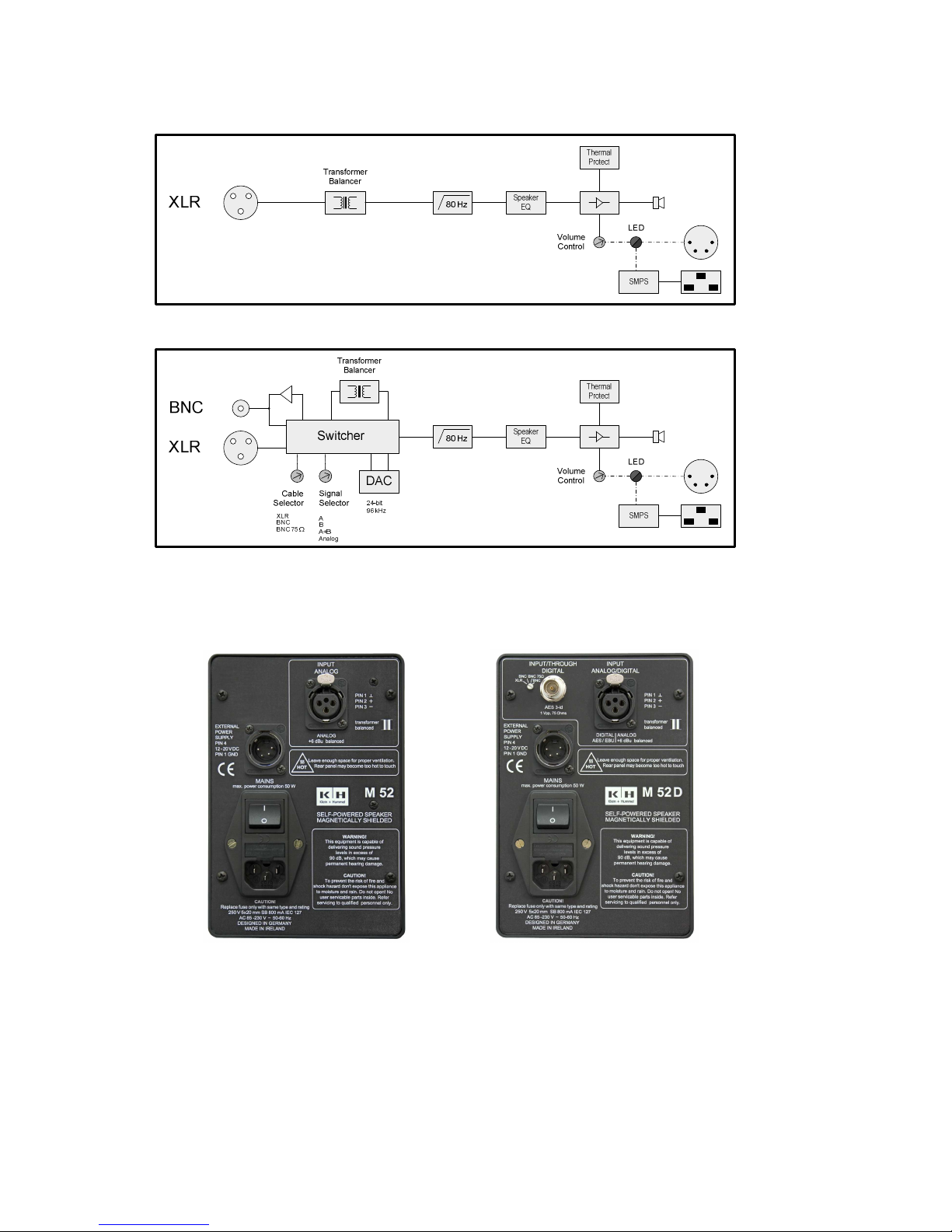
System Block Diagram
System Block DiagramSystem Block Diagram
System Block Diagram
M52 block diagram
M52 block diagramM52 block diagram
M52 block diagram
M52 D block diagram
M52 D block diagramM52 D block diagram
M52 D block diagram
Electronics
ElectronicsElectronics
Electronics Panel Picture
Panel Picture Panel Picture
Panel Picture
M 52
M 52M 52
M 52 electronics panel
electronics panel electronics panel
electronics panel M 52 D el
M 52 D elM 52 D el
M 52 D electronics panel
ectronics panelectronics panel
ectronics panel
Power Supply and Controls
Power Supply and ControlsPower Supply and Controls
Power Supply and Controls
The M 52 and M52 D have a switched-mode power supply, which can accept mains AC
voltages of 85…240 V at 50…60 Hz. In addition, DC can be applied to the 4-pin “external
power supply” connector (GND connects to pin 1, and 12…20 V connects to pin 4).
Page 5
Klein + Hummel
M 52 (D) Page 3
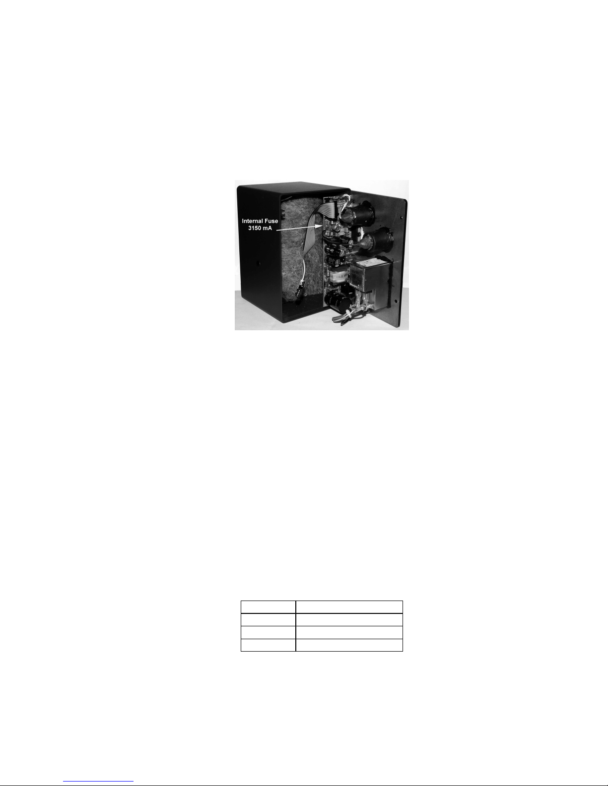
The loudspeaker is protected from accidental application of an incorrect polarity of the DC
voltage. The mains input fuse is a slow blow 800 mA and is accessible from the outside
(next to the main power On/Off switch). The external power supply input fuse is an SB
3150 mA and is located on the inside of the cabinet. To change this fuse:
• Turn off the loudspeaker and disconnect the mains power and signal cables.
• Open the cabinet (four screws on the edge of the back panel).
• Locate the fuse holder and change the fuse for a new one with the correct
specification (slow blow 3150 mA).
• Close the back panel and reattach the mains power and signal cables.
• Power up the loudspeaker and check that the front panel light is correctly illuminated.
For mains AC power:
The power On/Off
power On/Offpower On/Off
power On/Off switch on the back panel turns the loudspeaker on and off. If the
volume control
volume controlvolume control
volume control on the front panel is rotated fully anti-clockwise the loudspeaker is placed
into standby mode. If the back panel mains switch is on, standby is indicted by a red light
on the front panel. Otherwise it is green (loudspeaker is ready to be used) or off
(loudspeaker is switched off on back panel or no power applied to the external or mains
connectors).
For the external power supply:
The 4-pin XLR input bypasses the main power On/Off
power On/Offpower On/Off
power On/Off switch. There is no standby mode
when there is an external power supply. The LED lights green when the external power is
applied.
Analog
Analog Analog
Analog Input
Input Input
Input SSSStage
tagetage
tage
The input stage
input stageinput stage
input stage is a 10 kΩ transformer balanced type on a female XLR socket.
Pin
PinPin
Pin Signal
SignalSignal
Signal
1 Audio Ground
2 Positive
3 Negative
If there is a humming or buzzing sound coming from the loudspeaker, first check it is not
the loudspeaker by disconnection the input signal cables. If the noise goes away it is not
the loudspeaker itself and so the noises must be coming from the cabling (mains power or
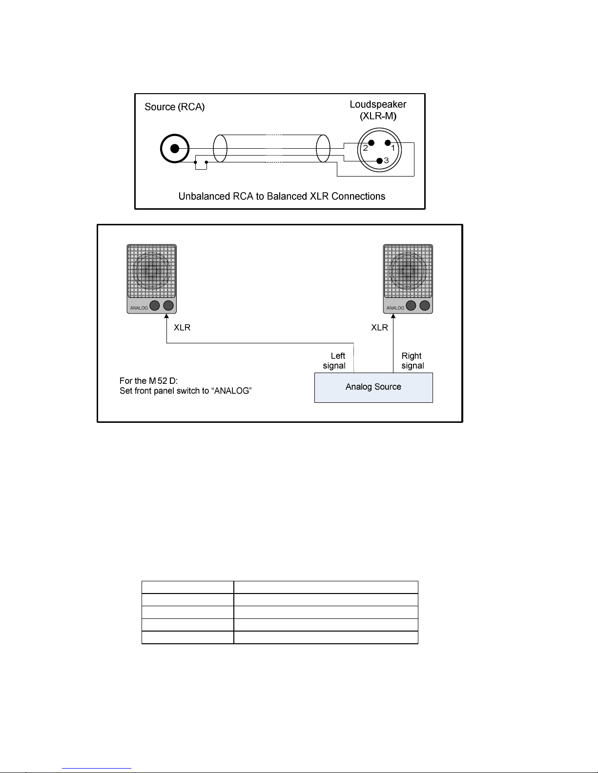
signal) or the source. If unbalanced cables are being used, specially wired cables can
increase the loudspeaker’s immunity from these external noises – see picture below.
Page 6
Klein + Hummel
M 52 (D) Page 4
Disconnect the cable screen from the RCA sleeve if there are still humming or buzzing
sounds.
Analog connections
Analog connectionsAnalog connections
Analog connections on the M 52 and M 52 D
on the M 52 and M 52 D on the M 52 and M 52 D
on the M 52 and M 52 D
Digital Input Stage (M 52 D only)
Digital Input Stage (M 52 D only)Digital Input Stage (M 52 D only)
Digital Input Stage (M 52 D only)
In the M 52 D there is a 16…
16…16…
16…24
2424
24----bi
bibi
bitttt,,,, 32…
32…32…
32…96
9696
96 kHz digital input stage
kHz digital input stage kHz digital input stage
kHz digital input stage that can accept AES32003 (commonly known as AES/EBU), AES3id-2001, and S/P-DIF (with a suitable
connector converter) signals. De-emphasis is supported on 32, 44.1, 48, and 96 kHz
sample rates. XLR and BNC connectors ensure good interconnectivity options. It is possible
to have analog and digital signals connected, with the rear panel cable
cablecable
cable selector
selector selector
selector switch
switch switch
switch
choosing which input connector is to be monitored. The table below shows what each
switch position does:
Switch Positio
Switch PositioSwitch Positio
Switch Positionnnn Function
FunctionFunction
Function
XLR Analog or digital signal on XLR
BNC Unterminated digital input on BNC
BNC 75 Ω Terminated digital input on BNC
BNC Same as “BNC” above
Uncompressed PCM AES3, AES3id, and S/P-DIF digital signals generally contain two audio
channels (called “subframe A” and “subframe B”) on one cable (single-wire mode). A
clock input is not required because loudspeakers are not audio sources and the clock
signal is locally regenerated from data contained in the bit stream. The four-way signal
signalsignal
signal
selector
selectorselector
selector switch
switch switch
switch on the front panel allows selection of:
Page 7

Klein + Hummel
M 52 (D) Page 5
• “L” (digital subframe A)
• “L+R” (mono sum of subframe A and subframe B)
• “R” (digital subframe B)
• “ANALOG” (XLR input connector only). Note the signal selector switch on the back
panel should be set to “BNC 75 Ω” when not using the digital input.
Always use good quality cables with the correct impedance to achieve these maximum
cable lengths:
Format (Connector)
Format (Connector)Format (Connector)
Format (Connector) Impedance
ImpedanceImpedance
Impedance Cable Length
Cable LengthCable Length
Cable Length
S/P-DIF (RCA)
75 Ω
up to 10 m (30’)
AES3 (XLR)
110 Ω
up to 100 m (300’)
AES3id (BNC)
75 Ω
up to 1000 m (3000’)
An AES3 signal (applied to the XLR connector) is point-to-point and may not be looped, so
the BNC connector is used to connect additional monitors to the AES3 signal. The signal
selector switch on the first loudspeaker should be set to the “XLR” setting. This outputs
an AES3id signal from the BNC connector for connecting additional monitors to the
original AES3 signal. The second loudspeaker should have its signal selector set to the
“BNC 75 Ω” setting. See picture below:
XLR digital
XLR digitalXLR digital
XLR digital input
input input
input connections on the M 52 D
connections on the M 52 Dconnections on the M 52 D
connections on the M 52 D
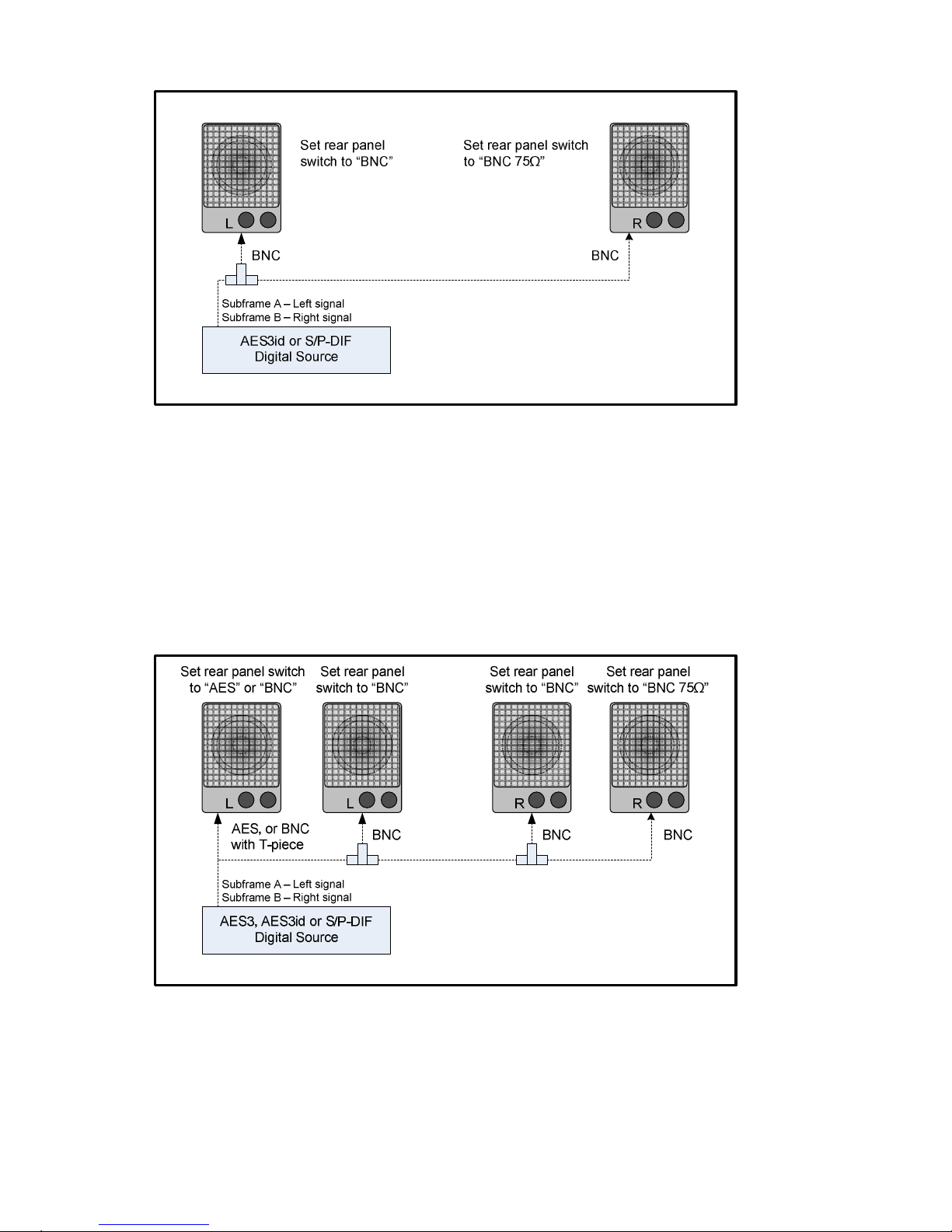
An AES3id or S/P-DIF signal (applied to the BNC connector) can be looped using a T-piece
connector (not supplied) for connecting additional monitors to the input signal. The signal
selector switch on the first loudspeaker should be set to the “BNC” setting. To terminate
the cable correctly, the second loudspeaker should have its signal selector switch set to
the “BNC 75 Ω” setting. An appropriate setting should be made on the front panel signal
selector switch depending on the signal channel order and loudspeaker position. See
picture below:
Page 8
Klein + Hummel
M 52 (D) Page 6
BNC digital
BNC digitalBNC digital
BNC digital input
input input
input connections on the M 52 D
connections on the M 52 Dconnections on the M 52 D
connections on the M 52 D
If there are multiple M 52 D monitors connected together using BNC T-piece connectors,
the first one should be set to “AES” or “BNC” as appropriate. The rest should be set to
“BNC”, except the last one which should be set to “BNC 75Ω”. Finally, an appropriate
setting should be made on the front panel signal selector switch depending on the
location of the loudspeaker.
Note that the BNC connector has no output driver. When using the AES3 input, the output
level is derived passively from the AES3 signal’s input level. This has a wide tolerance,
therefore the length of the interconnection cable and number of loudspeakers will depend
on the level of the source signal and quality of the interconnecting cables.
Multiple
Multiple Multiple
Multiple M 52 D
M 52 DM 52 D
M 52 D connections
connections connections
connections using BNC
using BNCusing BNC
using BNC
It is possible to have an analog XLR and a digital BNC cable simultaneously connected to
the loudspeaker. The signal selector switch is used to monitor the required input.
Page 9

Klein + Hummel
M 52 (D) Page 7
AES3id or S/P-DIF
Digital Source
Analog Source
Digital Signal
Analog Signal
Subframe A – Left signal
Subframe B – Right signal
BNC XLR
Left
signal
Right
signal
XLR BNC
L R
Set rear panel
switch to ““BNC”
Set rear panel
switch to “BNC 75Ω”
Simultaneous a
Simultaneous aSimultaneous a
Simultaneous analog
nalog nalog
nalog and digital
and digital and digital
and digital connections on the M 52 D
connections on the M 52 Dconnections on the M 52 D
connections on the M 52 D
Volume Control
Volume ControlVolume Control
Volume Control
A volume control
volume controlvolume control
volume control on the front panel allows the loudspeaker to be matched to a wide
range of equipment outputs whilst maintaining the desired acoustical output. This control
is also used to match the output level of the loudspeaker that of other loudspeakers in
the audio reproduction system. When the volume control is set to maximum, a +6 dBu
(1.55 V) input signal gives 100 dB SPL output at 1 m. The maximum input level that the
input stage can accept is +19 dBu (7 V). The maximum acoustical output of the
loudspeaker is limited by the protection system. In general, larger loudspeakers can play
louder and for longer periods than smaller loudspeakers. As with any other component in
the audio chain, it is best to use the lowest gain for the application so as to minimize
amplification of the preceding equipment’s source noise. To check this, if the noise drops
dramatically when the input cable is unplugged, the noise is coming from the source not
the loudspeaker.
Amplification and Driver
Amplification and DriverAmplification and Driver
Amplification and Driver
Amplifiers featuring low harmonic and intermodulation distortions, and low noise to
ensure a clean audio reproduction. Although no damage will result, insufficient cooling
will cause the amplifier protection to activate prematurely thereby limiting the system’s
maximum output level.
A long throw, efficient, low distortion driver ensures a clean sound quality even at high
replay levels. The driver is loaded by the internal volume of the cabinet and is
magnetically shielded for use near CRT screens or magnetic storage media. The system’s
SPL output and the cabinet volume can be seen in the specifications section.
Cabinet
CabinetCabinet
Cabinet
The aluminum cabinet is painted using the RAL color (7021). An appropriately colored
pen can be used to touch up the paintwork if it is scratched during transport or use.
Page 10
Klein + Hummel
M 52 (D) Page 8
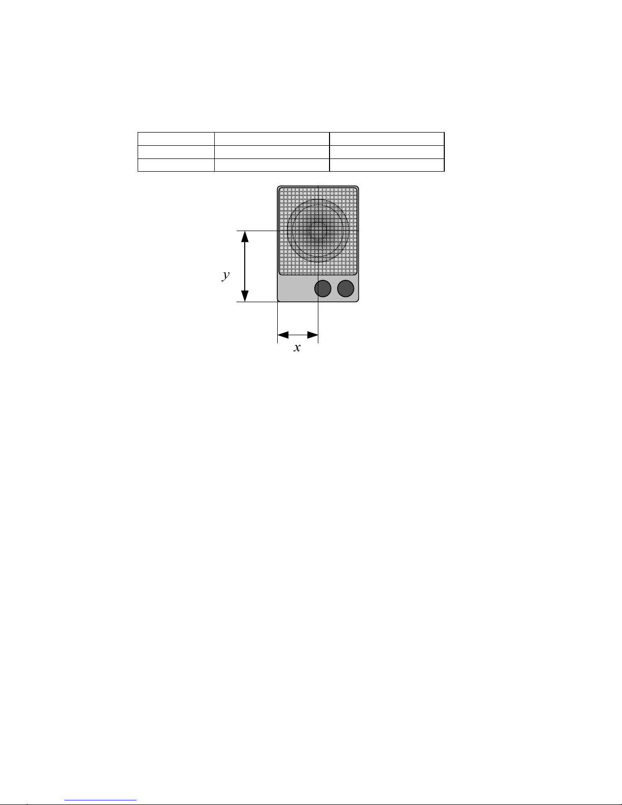
The acoustical axis is a line normal to the loudspeaker’s front panel along which the
microphone was placed when tuning the loudspeaker’s crossover during design. Pointing
the acoustical axis, in the horizontal and vertical planes, towards the listening position or
centre of the listening area will give the best measured and perceived sound quality. The
acoustical axis of Klein + Hummel’s control monitors is located in the middle of the driver.
Product
ProductProduct
Product x dimension
x dimensionx dimension
x dimension y dimension
y dimensiony dimension
y dimension
M 52 6.0 cm (2
3
/
8
“) 10.0 cm (3
7
/
8
“)
M 52 D 6.0 cm (2
3
/
8
“) 10.0 cm (3
7
/
8
“)
M 52 (D) Acoustical Axis
M 52 (D) Acoustical AxisM 52 (D) Acoustical Axis
M 52 (D) Acoustical Axis
Acoustical Response
Acoustical ResponseAcoustical Response
Acoustical Response
The M 52 and M 52 D have been designed to have a flat frequency response when used in
their typical application, on a meter bridge or mounted in a rack, however they will still
have a good response when used in other applications. If the sound quality is not
acceptable, try moving the loudspeaker or nearby objects until it is. An acoustical
measurement system can be used to help find the best location. In all cases, point the
loudspeaker towards the listening position to achieve the best sound quality.
System Protection
System ProtectionSystem Protection
System Protection
A high pass filter protects the amplifier and driver from high energy bass content that
cannot be reproduced by the smaller driver. If deeper bass is required, use a larger
loudspeaker, or add a subwoofer to handle the high-level low-frequency energy.
The amplifier has built-in thermal protection. The protection systems cannot protect
against sustained abuse of the loudspeaker.
Mounting Options
Mounting OptionsMounting Options
Mounting Options and
and and
and Accessories
AccessoriesAccessories
Accessories
The
3
/
8
” thread on the base of the cabinet may be used for attaching the M 52 or M 52 D
to a standard microphone stand. The M6 threads on either side of the cabinet can be used
with the LH 11 table stand and MA 19 rack mount frame.
Page 11

Klein + Hummel
M 52 (D) Page 9
FM 52
FM 52FM 52
FM 52 Fight case for a pair of M 52s
Fight case for a pair of M 52sFight case for a pair of M 52s
Fight case for a pair of M 52s or M 52 Ds.
or M 52 Ds. or M 52 Ds.
or M 52 Ds.
As the original packing is primarily designed to get the loudspeaker from the
factory to the end user, it is highly recommended that a flight case is used if the
loudspeaker is regularly moved between locations.
LH 11
LH 11LH 11
LH 11 Mounting bracket
Mounting bracketMounting bracket
Mounting bracket
Used to give vertically angle adjustment for the loudspeaker. Can be used on a
meter bridge, microphone stand, or other flat surface such as a wall.
MA 19
MA 19MA 19
MA 19 Rack mounting frame
Rack mounting frameRack mounting frame
Rack mounting frame
A 3U frame used to mount a pair of loudspeakers in to a 19” rack.
LH 11
LH 11 LH 11
LH 11 –––– Mountin
Mountin Mountin
Mounting bracket
g bracket g bracket
g bracket MA 19
MA 19 MA 19
MA 19 –––– Rack mounting frame
Rack mounting frame Rack mounting frame
Rack mounting frame
Detailed mechanical drawings of these accessories can be found on line at www.kleinhummel.com. Accessories are fitted at the user’s own risk and that safety and warning
instructions should be observed.
System Use
System UseSystem Use
System Use
Klein + Hummel loudspeakers should only be used indoors and in these ambient
conditions:
• +10° C to +40° C (+50° F to +104° F), <90% relative humidity, non-condensing
During transport or storage the ambient conditions can be:
• -25° C to +70° C (-13° F to 158° F), <90% relative humidity, non-condensing
Before connecting the mains power cable, ensure that the rear mains power and front
panel switches are set to off and that the correct mains voltage (85 … 240 V) or external
voltage (12 … 20 V) is available. Next connect the input signal cable (analogue, digital, or
both as appropriate) and power up the loudspeaker. The front panel light should be
glowing red or green depending on the position of the volume control. If the light is off,
check the mains or external power supply. In the M 52 D, select the required signal on the
front panel switch. Next raise the volume control until the desired audio level is achieved.
In a studio application, the loudspeakers should be placed according to the ITU-R BS.775-1
recommendations so there is consistency of reproduction when compared to other
listening environments. For movie applications, ANSI/SMPTE 202M is the preferred
standard for system setup. For home use, as materials are mixed in ITU style rooms, one
should get as close as possible to this configuration to maximize replay authenticity.
For two-channel stereo, ±30° should be used. There are currently no internationally
agreed standards for 6.1 or 7.1 formats. However common practice is to use one or two
loudspeakers in the centre back location of a 6.1 system. In a 7.1 system common practice
is to place side loudspeakers at ±90° and to push the surround loudspeakers back to
±150°.
Page 12
Klein + Hummel
M 52 (D) Page 10
Loudspeaker Name
Loudspeaker Name Loudspeaker Name
Loudspeaker Name ITU
ITUITU
ITU----R BS.775
R BS.775R BS.775
R BS.775----1 Angle
1 Angle1 Angle
1 Angle ANSI/SMPTE 202M
ANSI/SMPTE 202MANSI/SMPTE 202M
ANSI/SMPTE 202M Angle
AngleAngle
Angle
Left -30° -22.5°
Center 0° 0°
Right 30° 22.5°
Left Surround -110°±10° An array to the left
Right Surround 110°±10° An array to the right
For the best stereo imaging the loudspeakers should be placed symmetrical in a
symmetrical room where objects have been placed symmetrically. This ensures the same
response from each loudspeaker at the listening position and thus good imaging. Sound
reflected back to the listening position should also be minimized using surface angling or
acoustical treatment. The acoustical axis point towards the listening position or centre of
the listening area in both the horizontal and vertical planes.
If the loudspeaker is used free standing, use a strong microphone or good quality
loudspeaker stand. For placement in a rack or on a meter bridge, suitable accessories (see
Accessories and Options section) are recommended.
The loudspeakers should be placed on a circle to ensure equal time of arrival of the audio
from all loudspeakers. Failing this, appropriate electronic time delays should be added to
compensate for time of flight differences.
Next, trim the output level of each loudspeaker so that the SPL from each loudspeaker at
the listening position is the same for the same input level.
Absolute acoustic level calibration is achieved using a sound level meter set to ‘C’weighting and a “slow” integration time. Play a broadband pink noise test signal set to 18 dBFS (Europe) or -20 dBFS (USA) on the console meters and measure the sound
pressure level at the listening position. Then adjust each channel’s level (can also be
adjusted on all loudspeakers for a specific channel) until the desired level is achieved:
Application
Application Application
Application SPL
SPLSPL
SPL
Movie 85 dB(C)
Broadcast 79 dB(C)
Music Engineer’s preference
For information on setting up a subwoofer with these main loudspeakers, please refer to
the operating manual supplied with the subwoofer.
Page 13
Klein + Hummel
M 52 (D) Page 11
Technical Specifications
Technical SpecificationsTechnical Specifications
Technical Specifications
Acoustics
AcousticsAcoustics
Acoustics
Free field frequency response 90 Hz … 20 kHz, ± 5 dB
Self-generated noise
≤20 dB(A) at 10 cm
Max. SPL In half space at 3% THD 103.0 dB SPL
Averaged between 100 Hz and 6 kHz
Electronics
ElectronicsElectronics
Electronics
Amplifier, cont.(peak) output power* 24 W (40 W)
Controller design Analog, active
Protection circuitry Amplifier thermal
Infrasonic filter frequency; slope 80 Hz; 12 dB/oct.
Analog Input
Analog InputAnalog Input
Analog Input
Impedance, transformer balanced
XLR, 10 kΩ
Input sensitivity +6 dBu
Attenuator
0 … ∞ dB
CMRR >50 dB @ 15 kHz
Digital Input/Output
Digital Input/OutputDigital Input/Output
Digital Input/Output (M 52 D only)
(M 52 D only) (M 52 D only)
(M 52 D only) Optional
Format XLR (Format BNC) AES/EBU
(AES3id, S/P-DIF)
Impedance XLR, balanced
110 Ω
Impedance BNC, unbalanced
75 Ω
Input switching Analog/Digital A, B, Mono
Digital converter: resolution, design
16 … 24-bit DAC, ∆Σ
sampling rate 32 … 96 kHz
Display
DisplayDisplay
Display and Mains Power
and Mains Power and Mains Power
and Mains Power
Indicators: On Green
standby Red
Mains power 85 … 240 V AC
External power 12 … 20 V DC
M 52 (D) Power consumption - Idle 5 VA, 90 mA (7 VA, 125 mA)
M 52 (D) Power consumption - Full output AC 50 VA, 1.7 A (50 VA, 1.8 A)
Mechanics
MechanicsMechanics
Mechanics
Height x width x depth, mm 173 x 120 x 116 mm
inches 6 6/8” x 4 6/8” x 4 5/8"
Internal net volume 1.8 liters
M 52 Weight 1.7 kg (3.7 lbs)
M 52 D Weight 1.8 kg (4.0 lbs)
Drivers Magnetically shielded
Woofer 3", 75 mm
Mounting points 3/8” threaded inserts on base M6
threaded inserts on sides
Cabinet surface finish Painted
Color: standard Anthracite (RAL 7021)
Baffle cover Fixed metal grille
*THD+N < 0.1 % with limiter deactivated
Page 14

Klein + Hummel
M 52 (D) Page 12
Acoustical Measurements
Acoustical MeasurementsAcoustical Measurements
Acoustical Measurements
Below are acoustical measurements conducted in anechoic conditions at 1 m. Color
versions of these graphs can be found on the appropriate product page of the kleinhummel.com web site.
M 52 (D)
M 52 (D)M 52 (D)
M 52 (D) free
free free
free----field response
field responsefield response
field response M 52 (D)
M 52 (D)M 52 (D)
M 52 (D) Maximum
MaximumMaximum
Maximum SPL
SPL SPL
SPL output at 3% THD
output at 3% THD output at 3% THD
output at 3% THD
`
M 52 (D)
M 52 (D) M 52 (D)
M 52 (D) horizontal directivity plot
horizontal directivity plothorizontal directivity plot
horizontal directivity plot M 52 (D)
M 52 (D) M 52 (D)
M 52 (D) vertical directivity plot
vertical directivity plotvertical directivity plot
vertical directivity plot
M 52 (D)
M 52 (D) M 52 (D)
M 52 (D) group delay
group delaygroup delay
group delay M 52 (D) cumulate spectral decay
M 52 (D) cumulate spectral decayM 52 (D) cumulate spectral decay
M 52 (D) cumulate spectral decay
Page 15

Klein + Hummel
M 52 (D) Page 13
M 52 (D) dist
M 52 (D) distM 52 (D) dist
M 52 (D) distortion at 90 dB SPL
ortion at 90 dB SPLortion at 90 dB SPL
ortion at 90 dB SPL
Safety and Warnings
Safety and WarningsSafety and Warnings
Safety and Warnings
In addition to specific warnings throughout this document, please observe these additional general instructions.
This symbol means that a high voltage is to found nearby. Take appropriate precautions to avoid electric
shocks.
This symbol means that hot parts of the product may be found nearby. Take appropriate precautions to
avoid burns.
General
GeneralGeneral
General
• Keep these instructions in a safe place for future reference.
• Failure to follow the safety and warning instructions contained in this document voids the warranty.
• This product should be used for the intention for which it was designed and as described in this document.
Environment
EnvironmentEnvironment
Environment
• Ensure that the room in which you use this product is wired in accordance with the local electrical code and
checked by a qualified inspector.
• A correctly earthed mains power connection should always be used.
• If access to the interior electronics is required, disconnect it from the mains power and allow electrical energy
storage devices, such as capacitors and transformers, to discharge.
• Other electronic products may generate sufficient heat to require ventilation.
• Do not block or cover heatsinks, fans, or vents.
• Unless otherwise stated, this product is designed to be used indoors only.
• Do not expose this product to water, any other liquids, moisture, or naked flames.
• Do not install this product into hot, humid, or excessively dusty locations, or into direct sunlight.
• Avoid installing this product into locations where it will experience externally generated vibrations or heat (e.g.
radiators).
• If the product is moved from a cold environment into a warm one (such as from a vehicle into a building), it is
possible that condensation will form. Please allow the product sufficient time for acclimatization to room
temperature before using.
• Wherever an amplifier is located, a free flow of air should be maintained by leaving a gap of at least 5 cm (2”)
around it. A flush mounted cabinet with the electronics panel still installed should be well-ventilated to avoid heat
build-up and possible risk of fire.
Use
UseUse
Use
• The equipment should be mounted by a suitably qualified professional in accordance with local, national, and
international regulations and standards.
• Falling equipment can damage itself, people, and other objects, so do not place this unit on any unstable platform,
cart, trolley, stand, table, or mounting hardware.
• Do not use accessories and options with this product that are not approved by Klein + Hummel.
• Mounting hardware must be attached to the appropriate hardware and attachment points rated and intended for
such use.
• Ensure that the operating voltage of this product matches that of the local mains voltage.
• Use the power cable that came with this product as this has been manufactured to international safety standards.
If it has been damaged obtain a similarly certified and specified mains power cable.
• This product should be unplugged from the mains power and the signal sources if is not to be used for an
extended period of time, or during lightening storms.
Page 16

Klein + Hummel
M 52 (D) Page 14
• The power switch on this product should be set to off before applying mains power via the mains power cable.
• Some parts of this product, particularly power amplifier components, can become hot to the touch. Do not touch
these parts until they have cooled down.
• Never touch the loudspeaker’s drivers.
• Loudspeakers are often capable of producing a sound pressure level in excess of 85 dB. This may cause permanent
hearing damage so user caution is recommended. Noise exposure is a function of SPL and time, so observe local
regulations when listening at high levels for a long time. Hearing protection may be required.
Servicing
ServicingServicing
Servicing
• Repairs, maintenance, or other servicing of this product when its interior compartment is exposed should only be
performed by Klein + Hummel authorized service engineers familiar with the equipment and risks involved in
handling electronics.
• Servicing may be required in the event of exposure to unfavorable environmental conditions, such as liquids,
excessive heat, or a lightning strike.
• Amplifier outputs may carry high voltages so take appropriate precautions, for example, connect the cables before
powering up.
• When replacing a fuse, ensure that a brand new fuse is used. It must be exactly the same type, value, and voltage
as the original, as stated in the product’s technical specifications or on the circuit board.
Maintenance and Servicing
Maintenance and ServicingMaintenance and Servicing
Maintenance and Servicing
• There are no user serviceable parts inside the standard version of this product. Repairs should only be undertaken
by Klein + Hummel certified service engineer.
• Options and accessories are fitted at the user’s own risk.
• Products may be cleaned using a non-abrasive cloth lightly damped with water. Disconnect the mains power cable
when cleaning to avoid risk of electric shock. Do not use alcohol-based cleaners.
• The electronics should only be opened by non-“Klein + Hummel certified service engineer” for the installation of
user installable options as described in the product’s operating manual. The mains power cable should be
disconnected whenever the electronics panel is opened.
• If the main fuse blows, the product should be checked by a Klein + Hummel certified service engineer.
Guarantee
GuaranteeGuarantee
Guarantee
This product comes with a guarantee, a copy of which is enclosed with this product.
Recycling
RecyclingRecycling
Recycling
Attention to product quality in the design phase ensures, firstly, that products have a long life and that, secondly, all
parts of a product may be reused or recycled at the end of that life. An extensive product servicing network ensures
that products can be repaired in the event of the premature failure of a part, or as a way to prolong the life of a product
that would otherwise be considered a candidate for landfill. Eventually there comes a time when a product is considered
beyond repair (for economic reasons or lack of parts), so the parts must be disposed of in a suitable manner. The
disposal should conform to local environmental regulations and be conducted in an authorized recycling facility.
Loudspeakers and electronic products consist of some or all of these components:
Item
ItemItem
Item Material
MaterialMaterial
Material Recycling Instructions
Recycling InstructionsRecycling Instructions
Recycling Instructions
Loudspeaker Cabinets Wood (MDF), steel, aluminum, polyurethane
or a combination
Separate materials then recycle
Drivers Aluminum, copper, paper and plastics Separate materials then recycle
Damping Materials Sheep wool Compost
Electronics Panel Aluminum Remove electronics and recycle
Electronics Various Recycle in an approved recycling facility
Remote Electronics Kits Steel and some electronics Separate materials then recycle
Cables and Connectors Metals and/or plastic Reuse or recycle
Packing Material Cardboard, wood and/or plastics Separate materials then recycle
User Manuals and Sales
Literature
Paper and cardboard Recycle
EC Declaration of Conformity
EC Declaration of ConformityEC Declaration of Conformity
EC Declaration of Conformity
This equipment is in compliance with the essential requirements and other relevant provisions of Directives 89/336/EC
and 73/23/EC. The declaration is available on the internet site at www.klein-hummel.com. Before putting the device
into operation, please observe any respective country-specific regulations.
Page 17

Klein + Hummel
M 52 (D) Page 15
For loudspeakers fitted with digital inputs: Compliance to FCC Rules
For loudspeakers fitted with digital inputs: Compliance to FCC RulesFor loudspeakers fitted with digital inputs: Compliance to FCC Rules
For loudspeakers fitted with digital inputs: Compliance to FCC Rules
This device complies with part 15 of the FCC Rules and with RSS-210 of Industry Canada. Operation is subject to the
following two conditions:
• This device may not cause harmful interference, and
• This device must accept any interference received, including interference that may cause undesired operation.
This equipment has been tested and found to comply with the limits for a Class B digital device, pursuant to part 15 of
the FCC Rules. These limits are designed to provide reasonable protection against harmful interference in a residential
installation. This equipment generates, uses and can radiate radio frequency energy and, if not installed and used in
accordance with the instructions, may cause harmful interference to radio communications. However, there is no
guarantee that interference will not occur in a particular installation. If this equipment does cause harmful interference
to radio or television reception, which can be determined by turning the equipment off and on, the user is encouraged
to try to correct the interference by one or more of the following measures:
• Reorient or relocate the receiving antenna.
• Increase the separation between the equipment and receiver.
• Connect the equipment into an outlet on a circuit different from that to which the receiver is connected.
• Consult the dealer or an experienced radio/TV technician for help.
This class B digital apparatus complies with the Canadian ICES-003
Changes or modifications to this equipment not expressly approved by Klein + Hummel may void the FCC authorization
to operate this equipment.
Page 18

Klein + Hummel
M 52 (D) Page 16
Page 19

Page 20

Other company, product, or service names may be trademarks or service marks of other
organizations.
Klein + Hummel reserve the right to change product specifications without notice.
Exceptions and omissions excluded.
K+H Vertriebs- und Entwicklungsgesellschaft mbH
Auf dem Kessellande 4a, 30900 Wedemark, Germany.
Phone: +49 (5130) 58 48 0
Fax: +49 (5130) 58 48 11
E-mail: enquiries@klein-hummel.com
Web site: www.klein-hummel.com
 Loading...