

Page 1
058-E0015
Version 01/2003
Installation
Operation
KLEIN + HUMMEL GmbH
Zeppelinstrasse 12 • 73760 Ostfildern/Germany
Tel.: + 49/(0)711/ 45893 - 0
Fax: + 49/(0)711/ 45893 - 35
eMail: info@klein-hummel.de
Internet: www.klein-hummel.de
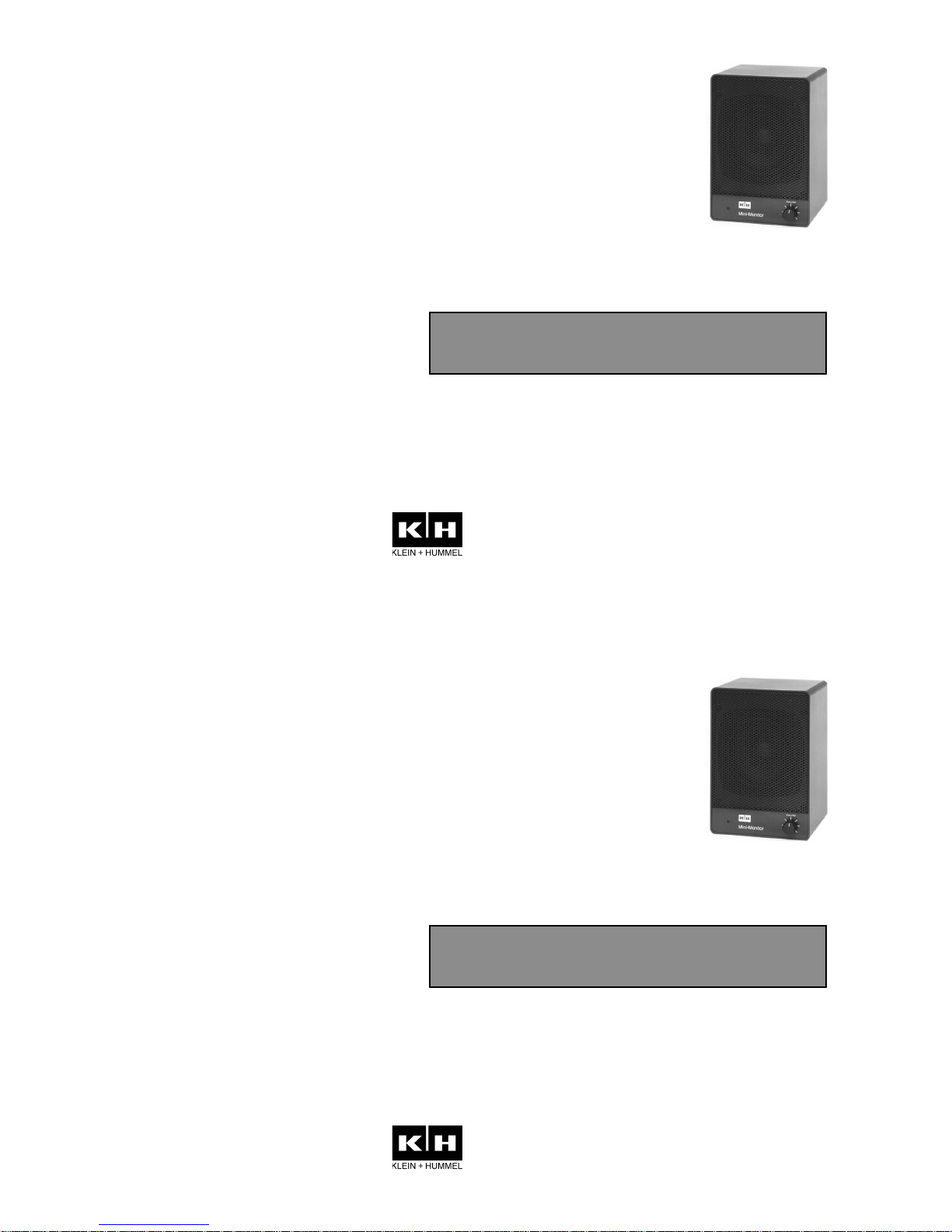
Active Control Monitor
M 50
058-E0015
Version 01/2003
Installation
Operation
KLEIN + HUMMEL GmbH
Zeppelinstrasse 12 • 73760 Ostfildern/Germany
Tel.: + 49/(0)711/ 45893 - 0
Fax: + 49/(0)711/ 45893 - 35
eMail: info@klein-hummel.de
Internet: www.klein-hummel.de
Active Control Monitor
M 50
Page 2

1. Safety Instructions
It is absolutely essential that you read these safety
instructions carefully before connecting and using this
K+H product. Your safety depends on it. Furthermore,
failure to follow these instructions voids the warranty. To
ensure safe operation for years to come, keep these
instructions in a safe place for future reference. K+H has
manufactured this product in accordance with IEC 1992 (SEC)
39 standards, then tested and delivered it in safe operating
condition. To maintain it in this condition, you must:
€ observe all safety instructions,
€ use the product only as described herein,
€ have any maintenance, repairs, or modifications performed
only by K+H or other authorized personnel, and
€ ensure that the room in which you use this product is wired
in accordance with the local electrical code.
Warning!
€ When the interior of the cabinet is exposed, touching some
parts can lead to an electric shock.
€ If you need to gain access to the interior electronics of the
unit, always disconnect the unit from any and all power
sources first.
€ Any repairs, maintenance, or other service of the unit when
its interior compartment is exposed may only be performed
safely (in accordance with VBG 4) by authorized technicians
familiar with all the risks involved. Even in an unplugged
state, a fully charged capacitor in the unit can zap the
unsuspecting.
€ Loudspeaker output jacks labeled with the IEC 417/5036
emblem (Fig. A, right) may be carrying dangerously high
voltages. If your unit has this emblem, ensure that any
connections to be made between these jacks and the
speakers themselves are made before powering up the
unit, and are done so only with manufacturer-approved
interconnecting cables.
€ If you need to replace any fuses, ensure that the
replacements are of exactly the same type, value and
voltage as the originals, as spelled out in the technical
specifications at the rear of this manual.
€ Do not use "repaired" fuses.
€ If you do not have any fuses on hand of the specified size,
type, and value, do not hot-wire the contacts in the holder
by short-circuiting them.
€ Certain areas of the cabinet, cover, and rear panel can
achieve extreme temperatures and are therefore marked
with a "HOT" label (Fig. B). Refrain from touching any heat
sink or ventilation grille.
€ High volume levels are known to cause permanent - i.e.
irreversible - hearing damage, especially when listened to
without sufficient breaks. The higher the levels, the more
frequent and extended must be the breaks. Avoid standing
too close to loudspeakers that are being driven at high
levels. If you must be exposed to high sound pressure levels
over an extended period of time, use hearing protection.
Mains Connection:
€ This unit is designed for continuous operation.
€ Ensure that the operating voltage of the unit matches that
of the local mains current (AC line voltage).
Page 3
€ Always check before connecting the power cable to the
mains socket that the power switch on the unit itself is set
to off ("O").
€ Use the power cable or power supply that came with the
unit to connect to the mains socket (wall outlet).
€ Power supply: a damaged power cable may not be repaired.
Use a new cable.
€ Avoid plugging the mains cable into a power strip that
already has several other power-consuming devices
connected to it.
€ Avoid using extension cables. The unit must be connected
to a mains socket close to it, and that socket should be
freely accessible.
Installation:
€ This product may only be placed on a stable, clean, hori-
zontal surface.
€ Do not expose this product to vibration.
€ Do not operate this product anywhere near water or other
liquids. Do not use it near a sink, swimming pool, bathtub,
or in any damp room or area. Electrical shocks carried
through water can kill. Do not place any beverages
whatsoever on or near this product, as liquids can kill
electronic components.
€ Ensure sufficient ventilation around the product to allow
for adequate heat dissipation, especially near the rear panel
and the sides of the cabinet (minimum of 8 inches from the
nearest wall). The unit may only be installed in a rack if
measures are taken to ensure sufficient ventilation and if
the mounting instructions of the manufacturer are followed.
Do not block or cover any heat sink, fan, or vent.
€ Do not place the product where it will be in the path of
direct sunlight, and keep it a safe distance away from
radiators and other heaters of any kind.
€ If you bring this product from a cold environment into a
warm one (such as from a vehicle into a studio), it is quite
possible that condensation will form inside the cabinet.
Please allow the unit sufficient time for acclimatisation to
room temperature (minimum thirty minutes) before
connecting and powering up.
€ To avoid accidents, do not use any accessory equipment
with this product which is not approved by the manufacturer,
particularly mounting accessories. Do not place this unit
on any unstable platform, cart, stand or table. Should the
unit fall, it can cause bodily injury to persons, or can be
damaged itself.
€ To protect this product from lightning damage during a
thunderstorm or from power surges during an extended
absence, disconnect the power cable from the wall outlet.
Fig. BFig. A
Page 4

2. Installation
2.1. Power source
The amplifier electronics of the standard European model are
set up for an AC line voltage of 230 volts, 50 or 60 Hz. Export
versions with other
voltages are also
available. Additionally
operation from a 12 to
14 V DC source is
provided. The DC
connectors (6.35 mm flat
plugs) are hidden under
a plastic cover. A non
reversable plug case is
delivered with the
speaker. Be sure of the
correct polarity as shown
on the imprint. A
protection diode prevents
from damage caused by
wrong polarity.
2.2 Operating
conditions
The K+H model M 50 active control monitor is intended for
use over a range of ambient temperatures from +10° C to
+40° C (+50° F to +104° F). During transport or storage,
temperatures from -25° C to +70° C (-13° F to 158° F) are
permissible.
2.3. AF - Input
The sensitivity of the transformer-balanced floating input is
+6 dBu (1.55 volts rms). Changing an internal resistor results
in a sensivity of 0 dBu (0.775 volt rms). The three-pin female
XLR jack is wired in the standard manner (pin 1 = ground, pin
2 = +, pin 3 = -). If you are connecting unbalanced analog
sources, you will need to solder a bridge between pins 1 and
3:
unbalanced balanced
as seen from the solder terminals of male XLR
Please observe, that the analog input level does not
exceed 7 volts rms.
2.4 Mains switch
The mains switch is located on the back of the speaker. A red
LED on the front side indicates the correct operation.
2.5 Volume control
The volume control is located on the front panel. The maximum
sensitivity of 1,55 V is achieved at full clockwise position.
Page 5

2.6 Mounting
On the bottom there is a 3/8" threaded bushing for mounting
the M 50 on a standard microphone tripod. The LH 11 table
mount bracket can be fixed to the two M6 threaded holes in
the sides and so allows rotation around horizontal and vertikal axis.
2.7Mains and Battery Fuses
The mains fuse is to be found on the rear panel, close to
mains connector whereas the battery fuse is only accessible
after removing the rear panel. Before changing fuses all power
sources have to be disconnected. Only the following fuses
5x20 mm may be used:
mains 230 V AC 0.2 A slow blow
mains 117 V AC 0.4 A slow blow
mains 100 V AC 0.5 A slow blow
battery 12 - 14 V DC 2.5 A slow blow
2.8Groundlift
Since the input is transformer balanced and floating, you should
rarely experience any hum. In unusual
cases, or if the source is unbalanced,
it may be necessary to lift the
connection between signal ground and
chassis ground (connected to
protective earth, PE), in which case you
will find a wire bridge inside the
amplifier - see figure beside. On
delivery the shown connection is closed and can be opened if
a hum interference occurs.
Warning!
Never disconnect the protective earth (PE) of the mains
power cable from the chassis ground!
2.9Positioning
The loudspeaker chassis used in the M 50 is magnetically
shielded, so you are free to set the speakers right next to a
video monitor without needing to worry about adversely
affecting the screen. The sophisticated M 50 design gained in
an unified and neutral sound within the nearfield zone. Best
results are achieved within a hearing distance of 1 to 1.5 m.
Stereo pairs should be turned to the hearing area.
3. Operation
3.1 Mains switch
The power switch on the rear side activates the power supply
of the amplifier from both mains and battery sources. AC and
DC - input may be connected simultaneously. A red LED in
the front panel indicates, that the control monitor is ready.
3.2 Monitoring loudness
The M 50 is designed for nearfield monitoring. For best
performance and reliability it is recommended to avoid exessive
boosting of bass and treble by extern sound contols due to
large monitoring distances or bad positioning.
Page 6

3.3 Volume control
The volume control on the front side can be set down to minus infinity.
4. Warranty Information
All K+H products undergo an extensive procedure of quality
control testing before leaving the factory. Before
semiconductors are mounted on the circuit board, they are
subject to rigorous tests. Every single unit is guaranteed to
match its technical specifications within strict predetermined
tolerances.
Please store the original carton in a safe, dry place. If you
should ever need warranty service, put the unit in its original
packing material and carton together with a detailed
description of the problem, and ship it (freight prepaid) to our
distributor or directly to:
KLEIN + HUMMEL GmbH
Customer service
Zeppelinstrasse 12
73760 Ostfildern / Germany
K+H warrants, that the product is free from any defects in both
material and manufacturing and that it meets the specifications.
A warranty case can only be acknowledged under condition
that the complaint is filed to our distributor or to us in writing
within 8 days after delivery or detection of the fault. Not
covered under this warranty are damages due to inexpert
packing and shipment, wear and tear, improper handling,
installation, operation and maintenance.
The limitation period for warranty claims is described in the
terms and conditions of K+H GmbH. Its our choice to repair,
to supply a new product or to withdraw from the contract.
In the event warranty service is required, presentation of a
warranty card will not be necessary. Proof of purchase date
can be made by filing copies of appropriate documents
(invoice, delivery note).
Page 7

Specifications M 50
Free-field frequency response 120 Hz - 15 kHz ± 5 dB
Self generated noise @ 10 cm < 20 dB (A)
Total harmonic distortion
above 350 Hz < 1 % @ 80 dB / SPL / 1m
Max. sound pressure level
in half-space, 3% THD 100 dB/SPL
averaged between 100 Hz and 6 kHz
Electronics
Amplifier power output
Mains operation 14 W 4 Ohm THD < 0.1 %
Battery operation 12 volts 10 W 4 Ohm THD < 0.1 %
Battery operation 14 volts 14 W 4 Ohm THD < 0.1 %
Equalization optimized for near field
monitoring
Input
Connector XLR 3
Impedance 20 kOhm, transformer-
balanced and floating
Sensivity + 6 dBu (1.55 volts)
Volume control 0... - infinite dB
CMRR > 50 dB @15 kHz
Mains voltage 230 volts AC, 50/60 Hz
Eport versions 117 / 100 V AC, 50/60 Hz
Connector 3 - terminal Euro connector
Battery voltage 12 - 14 volts DC
Connector 6.35 x 0.8 mm flat plug x2
Power consumption
Idle mains operation 2 VA
Idle battery operation 90 mA
Full power mains operation 27 VA
Full power battery operation 14 V 1.7 A
Fuses 5x20 mm
Mains 230 volts AC 0.2 A slow blow
Mains 117 volts AC 0.4 A slow blow
Mains 100 volts AC 0.5 A slow blow
Battery 12 - 14 volts DC 2.5 A slow blow
Mechanical specs
Dimensions
W x H x D 120 x 173 x 116 mm
Volume 2.4 litres
Weight 2.6 kg
Driver magnetically shielded 100 mm / 4"
Mounting options 3/8" threaded bushing on
bottom,2x M6 on sides
Mounting adaptors LH 11 table mount bracket
Cabinet
Material aluminium
Finish lacquered dark brown,
later charcoal-grey (RAL 7021)
others optional (add - on price)
Baffle cover fixed metal grille
Specifications M 50
Free-field frequency response 120 Hz - 15 kHz ± 5 dB
Self generated noise @ 10 cm < 20 dB (A)
Total harmonic distortion
k2 and k3 above 350 Hz < 1 % @ 80 dB / SPL / 1m
Max. sound pressure level
in half-space, 3% THD 100 dB/SPL
averaged between 100 Hz and 6 kHz
Electronics
Amplifier power output
Mains operation 14 W 4 Ohm THD < 0.1 %
Battery operation 12 volts 10 W 4 Ohm THD < 0.1 %
Battery operation 14 volts 14 W 4 Ohm THD < 0.1 %
Equalization optimized for near field
monitoring
Input
Connector XLR 3
Impedance 20 kOhm, transformer-
balanced and floating
Sensivity + 6 dBu (1.55 volts)
Volume control 0... - infinite dB
CMRR > 50 dB @15 kHz
Mains voltage 230 volts AC, 50/60 Hz
Eport versions 117 / 100 V AC, 50/60 Hz
Connector 3 - terminal Euro connector
Battery voltage 12 - 14 volts DC
Connector 6.35 x 0.8 mm flat plug x2
Power consumption
Idle mains operation 2 VA
Idle battery operation 90 mA
Full power mains operation 27 VA
Full power battery operation 14 V 1.7 A
Fuses 5x20 mm
Mains 230 volts AC 0.2 A slow blow
Mains 117 volts AC 0.4 A slow blow
Mains 100 volts AC 0.5 A slow blow
Battery 12 - 14 volts DC 2.5 A slow blow
Mechanical specs
Dimensions
W x H x D 120 x 173 x 116 mm
Volume 2.4 litres
Weight 2.6 kg
Driver magnetically shielded 100 mm / 4"
Mounting options 3/8" threaded bushing on
bottom,2x M6 on sides
Mounting adaptors LH 11 table mount bracket
Cabinet
Material aluminium
Finish lacquered dark brown,
later charcoal-grey (RAL 7021)
others optional (add - on price)
Baffle cover fixed metal grille
Page 8

KLEIN + HUMMEL GmbH
Zeppelinstrasse 12 • 73760 Ostfildern/Germany
Tel.: + 49/(0)711/ 45893 - 0
Fax: + 49/(0)711/ 45893 - 35
eMail: info@klein-hummel.de
Internet: www.klein-hummel.de
KLEIN + HUMMEL GmbH
Zeppelinstrasse 12 • 73760 Ostfildern/Germany
Tel.: + 49/(0)711/ 45893 - 0
Fax: + 49/(0)711/ 45893 - 35
eMail: info@klein-hummel.de
Internet: www.klein-hummel.de
 Loading...