

Page 1
Operating Manual
Manuel Utilisateur
Bedienungsanleitung
K8-AI8 K8-AO2
K8-AO8 K8-ESB
K8
Digital Audio Distribution System
Page 2
Page 2 K8 Rackmount Family User Manual
Safety Instructions
It is absolutely essential that you read these safety instructions carefully before connecting and
using this K+H product. Your safety depends on it. Failure to follow these instructions voids the
warranty.
To ensure safe operation for years to come, keep these instructions in a safe place for future reference. K+H has
manufactured this product in accordance with IEC 92 (SEC) 39 standards, then tested and delivered it in safe operating
condition. To maintain it in this condition, you must:
•
observe all safety instructions
•
use the product only as described herein
•
have any maintenance, repairs, or modifications performed only by K+H or other authorized personnel
•
ensure that the room in which you use this product is wired in accordance with the local electrical code
Warning!
Warning!Warning!
Warning!
•
When the interior of the cabinet is exposed, touching some parts can lead to an electric shock.
•
If you need to gain access to the interior electronics of the unit, always disconnect the unit from any and all
power sources first.
•
Any repairs, maintenance, or other service of the unit when its interior compartment is exposed may only be
performed safely (in accordance with VBG 4) by authorized technicians familiar with all the risks involved. Even
in an unplugged state, a risk of electric shock is possible.
Fig. A
•
If you need to replace any fuses, ensure that the replacements are of exactly the same type, value and voltage
as the originals, as spelled out in the technical specifications at the rear of this manual.
•
Do not use "repaired" fuses.
•
If you do not have fuses of the specified size, type and value, do not hot-wire the contacts in the holder by
short-circuiting them.
•
Certain areas of the cabinet, cover, and rear panel can achieve extreme temperatures and are therefore marked
with a "HOT" label (Fig. B). Refrain from touching any heat sink or ventilation grille.
•
High volume levels are known to cause permanent - i.e. irreversible - hearing damage, especially when listened
to without sufficient breaks. The higher the levels, the more frequent and extended must be the breaks. Avoid
standing too close to loudspeakers that are being driven at high levels. If you must be exposed to high sound
pressure levels over an extended period of time, use hearing protection.
Fig. B
Mains Connection:
Mains Connection:Mains Connection:
Mains Connection:
•
This unit is designed for continuous operation.
•
Ensure that the operating voltage of the unit matches that of the local mains current (AC line voltage).
•
Always check before connecting the power cable to the mains socket that the power switch on the unit itself is set to off
("O").
•
Use the power cable or power supply that came with the unit to connect to the mains socket (wall outlet).
•
Power supply: a damaged power cable may not be repaired. Use a new cable.
•
Avoid plugging the mains cable into a power strip that already has several other power-consuming devices connected to
it.
•
Avoid using extension cables. The unit must be connected to a mains socket close to it, and that socket should be freely
accessible.
Installation:
Installation:Installation:
Installation:
•
Installation and overhead rigging of this product must be conducted by a qualified professional according to applicable
local, national and international codes and standards. Mounting brackets supplied by the manufacturer must be
attached to appropriate hardware and attachment points rated and intended for such use.
•
Do not expose this product to vibration.
•
Do not operate this product anywhere near water or other liquids. Do not use it near a sink, swimming pool, bathtub, or
in any damp room or area. Electrical shocks carried through water can kill. Do not place any beverages whatsoever on or
near this product, as liquids can kill electronic components.
•
Ensure sufficient ventilation around the product to allow for adequate heat dissipation, especially near the rear panel
and the sides of the cabinet (minimum of 8 inches from the nearest wall). The unit may only be installed in a rack if
measures are taken to ensure sufficient ventilation and if the mounting instructions of the manufacturer are followed.
Do not block or cover any heat sink, fan, or vent.
•
Keep this product a safe distance away from radiators and other heaters of any kind.
•
If you bring this product from a cold environment into a warm one, it is quite possible that condensation will form inside
the cabinet. Please allow the unit sufficient time for acclimation to room temperature (minimum thirty minutes) before
connecting and powering up.
•
To avoid accidents, do not use any accessory equipment with this product that is not approved by the manufacturer,
particularly mounting accessories.
•
Do not place this unit on any unstable platform, cart, stand or table. If the unit falls, it can cause bodily injury to persons,
or can be damaged itself.
•
To protect this product from lightning damage during a thunderstorm or from power surges during an extended
absence, disconnect the power cable from the wall outlet.
Page 3

K8 Rackmount Family User Manual Page 3
Table of Contents
Safety Instructions 2
K8 Product Family Operating Manual 5
K8 Series Overview ............................................................................................................................................5
Quick Start Information....................................................................................................................................5
Using Input Devices...........................................................................................................................................5
Using Output Devices........................................................................................................................................5
Connecting a Control System...........................................................................................................................6
Monitoring with a PC.........................................................................................................................................6
Category 5 Cable Color Code ............................................................................................................................6
Frequently Asked Questions (FAQ) ................................................................................................................6
Manufacturer’s Declarations 7
CE Declaration of Conformity...........................................................................................................................7
K8-AI8 Product Manual Section 8
Rear Panel Description......................................................................................................................................8
Front Panel Description ....................................................................................................................................8
Overview .............................................................................................................................................................9
Stacking Input Devices .....................................................................................................................................9
Termination Setting ..........................................................................................................................................9
Control and Monitoring ....................................................................................................................................9
Input Level Settings ....................................................................................................................................... 10
Front Panel LEDs ............................................................................................................................................. 10
Compatible Accessories ................................................................................................................................. 10
K8-AI8 Technical Specifications ................................................................................................................... 11
Electrical ........................................................................................................................................................... 11
Mechanical........................................................................................................................................................ 11
K8-AO8 Product Manual Section 12
Rear Panel Description................................................................................................................................... 12
Front Panel Description ................................................................................................................................. 12
Overview ..........................................................................................................................................................12
Routing Capabilities ....................................................................................................................................... 13
Stacking Output Devices ............................................................................................................................... 13
Termination Setting ....................................................................................................................................... 13
Control and Monitoring ................................................................................................................................. 13
Output Level Settings .................................................................................................................................... 13
Front Panel LEDs ............................................................................................................................................. 14
Compatible Accessories ................................................................................................................................. 14
K8-AO8 Technical Specifications.................................................................................................................. 15
Electrical ........................................................................................................................................................... 15
Mechanical........................................................................................................................................................ 15
Page 4

Page 4 K8 Rackmount Family User Manual
K8-AO2 Product Manual Section 16
Rear Panel Description................................................................................................................................... 16
Front Panel Description ................................................................................................................................. 16
Overview ..........................................................................................................................................................17
Routing Capabilities ....................................................................................................................................... 17
Stacking Output Devices ............................................................................................................................... 17
Termination Setting ....................................................................................................................................... 17
Control and Monitoring ................................................................................................................................. 17
Output Level Settings .................................................................................................................................... 17
Front Panel LEDs ............................................................................................................................................. 18
Compatible Accessories ................................................................................................................................. 18
K8-AO2 Technical Specifications.................................................................................................................. 19
Electrical ........................................................................................................................................................... 19
Mechanical........................................................................................................................................................ 19
K8-ESB Product Manual Section 20
Rear Panel Description................................................................................................................................... 20
Front Panel Description ................................................................................................................................. 20
Overview ..........................................................................................................................................................21
Rack Mounting ................................................................................................................................................ 21
Routing Capabilities ....................................................................................................................................... 21
Stacking Input Devices .................................................................................................................................. 21
Termination Setting ....................................................................................................................................... 22
Control and Monitoring ................................................................................................................................. 22
Compatible Accessories ................................................................................................................................. 22
K8-ESB Technical Specifications ................................................................................................................... 23
Electrical ........................................................................................................................................................... 23
Mechanical........................................................................................................................................................ 23
Page 5
K8 Rackmount Family User Manual Page 5
K8 Product Family Operating Manual
Read this section first as it explains the overall system theory of all K8 devcies in the family. Additional
manual sections contain the details for specific model number.
K8 Series Overview
K8 is a digital audio distribution system. It allows for the transport of 16 digital audio signals over a single
Category 5 cable along with control data. The audio signal travels in one direction only, from the input
device to the output device. Control data is bi-directional.
Quick Start Information
K8 devices are factory configured to begin passing audio immediately after powered up in the simple case
where 8 input channels are sent to 8 output channels. More complex settings and configurations are
possible if desired by using the K8 terminal control protocol. For example, configuring an 8 channel output
device to select channels 9-16 instead of 1-8 is done using the K8 terminal control protocol.
Using Input Devices
Input devices are used to put audio onto the K8 bus while output devices are used to get audio out of the
K8 bus.
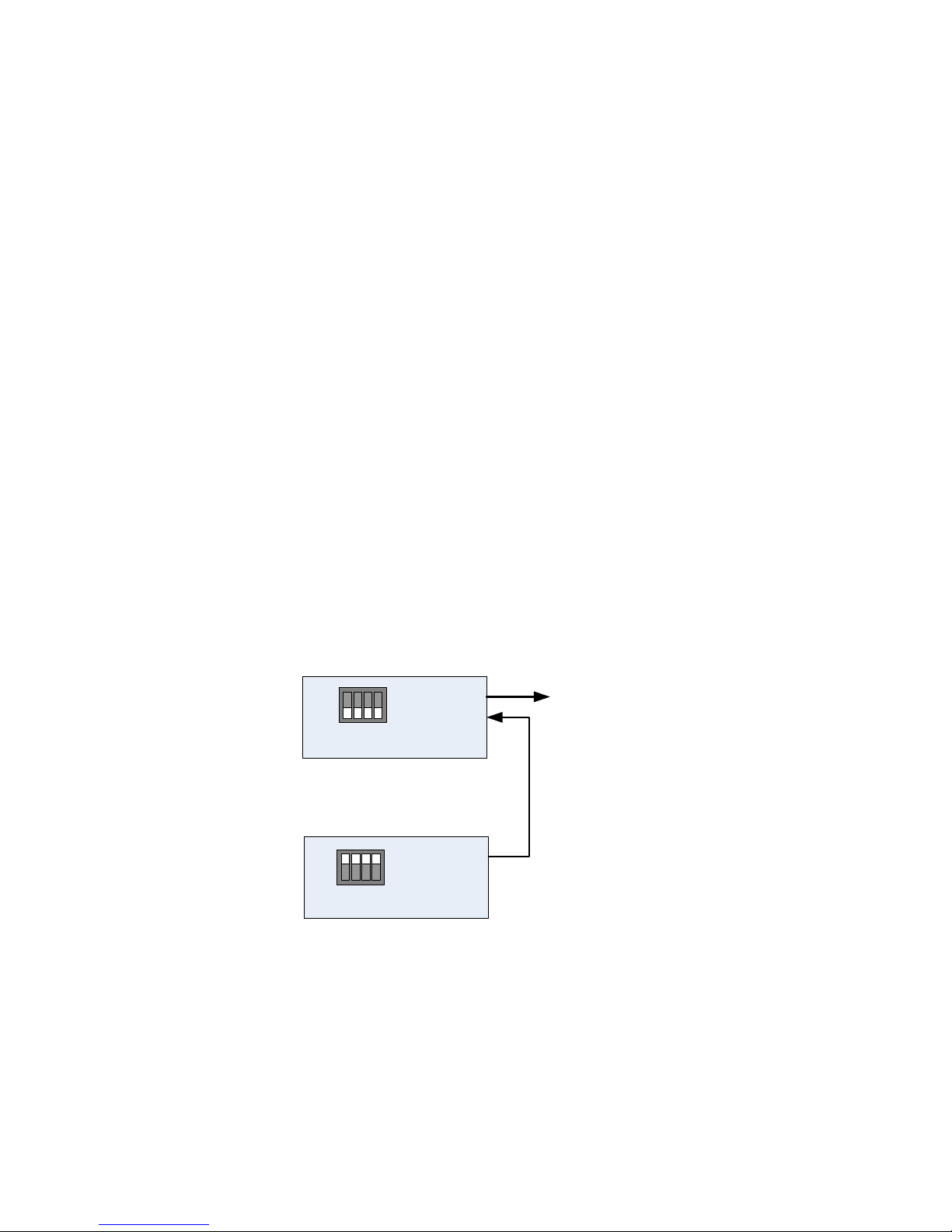
Two 8-channel devices may be stacked up to populate all the available 16 channels on a K8 cable. For
example, 16 analogue inputs are obtained by stacking quantity (2) K8-AI8 devices.
Stacking two devices is accomplished using a standard Ethernet crossover cable to connect the K8 Out 2 of
the first device to the K8 Out 1 of the second device. The K8 Out 1 of the first device is then used to drive
the K8 bus.
K8 Out 1
K8-AI8 Analogue Input
K8 Out 2
K8 Out 1
K8-AI8 Analogue Input
K8 Out 2
Term
On
Not Used
Term
On
Cat 5 Crossover Cable
Out to
Distribution
K8 Channel Inputs 9-16
K8 Channel Inputs 1-8
Using Output Devices
TERMINATION RULE: The first and last device on each K8 chain must have their termination switches set. If
both K8 ports on a device are used, the 4 switches are on. If one of the K8 ports on a device is not
connected, the switches are off. The K8 terminal control protocol is able to monitor the termination switch
settings remotely.
Page 6

Page 6 K8 Rackmount Family User Manual
Input devices are used to put audio onto the K8 bus while output devices are used to get audio out of the
K8 bus.
Output devices may be daisy chained until the maximum cable length of 200 meters has been reached.
Output devices are passively connected and do not refresh the K8 audio signal. This architecture has the
benefit that a failure of an output device will still allow audio to pass to the next device in the chain. Daisy
chaining devices introduces no delay in the audio signal.
Connecting a Control System
The status of all K8 devices in a system may be remotely controlled and monitored through the RS-485
port on the input device. The control signal passes through the same cable as the audio signals and
requires no special installation. The protocol is openly published on www.klein-hummel.com for use by
software engineers and control system programmers.
Monitoring with a PC
It is possible to monitor and control the devices in a K8 system using a terminal program and the K8
terminal control protocol. Instructions for its use are available on the website at www.klein-hummel.com.
Some K8 devices are connected to the PC with an RS-485 port and some are connected with an Ethernet
port. It is possible to purchase a USB/485 adapter. Please refer to the section of the manual for this
specific device.
Category 5 Cable Color Code
The K8 system utilizes the same cabling and pin standards as Ethernet, although K8 is not an Ethernet
protocol.
K8 system cables should be terminated according to standard TIA/EIA-568A or standard TIA/EIA-568B.
Both standards create a straight through cable as long as the same color code standard is used on both
ends. Creating a crossover cable is accomplished by terminating one end as 568A and terminating the
opposite end as 568B.
Frequently Asked Questions (FAQ)
What is K8?
What is K8?What is K8?
What is K8?
K8 is an easily implemented and robust method of distributing digital audio and control signals across a
facility or between two audio devices with low latency and professional audio quality.
What audio format is used in K8?
What audio format is used in K8?What audio format is used in K8?
What audio format is used in K8?
Currently available products are uncompressed digital 24 bit, 48 kHz sample rate.
How many channels are available w
How many channels are available wHow many channels are available w
How many channels are available with K8?
ith K8?ith K8?
ith K8?
Up to 16 audio channels may be placed on a single cat 5 cable, as two sets of 8.
How are the cables terminated?
How are the cables terminated?How are the cables terminated?
How are the cables terminated?
All cables are terminated with RJ-45 connectors using the color code defined by either EIA-568A or EIA568B as long as all ends are terminated using the same standard.
How do I get 16 audio channels on the K8 system when the input box K8
How do I get 16 audio channels on the K8 system when the input box K8How do I get 16 audio channels on the K8 system when the input box K8
How do I get 16 audio channels on the K8 system when the input box K8----AI8 only has 8 inputs?
AI8 only has 8 inputs?AI8 only has 8 inputs?
AI8 only has 8 inputs?
Up to two input units such as the K8-AI8 (analogue line input) may be used to place audio onto the K8
bus. One of the two input units must be connected to the system via a standard category 5 crossover
cable.
How do I make a cat 5 crossover cable?
How do I make a cat 5 crossover cable?How do I make a cat 5 crossover cable?
How do I make a cat 5 crossover cable?
Wire one end according to the color code EIA-568A and the other end according to the color code EIA568B. In the K8 system a crossover cable is used to stack two input devices such as the K8-AI8 onto the
same cable. All other cat 5 cables are wired straight through.
Page 7

K8 Rackmount Family User Manual Page 7
How far can you run a K8 cable?
How far can you run a K8 cable?How far can you run a K8 cable?
How far can you run a K8 cable?
One K8 distribution leg can be run a total length of 200 meters no matter how many devices are connected
along the way.
How much delay is in the K8 system?
How much delay is in the K8 system?How much delay is in the K8 system?
How much delay is in the K8 system?
K8 has a total through delay of 1/2 ms. Adding K8 output devices adds no delay to the signal path
because all K8 devices, except for distribution amplifiers, are passive.
If a single K8
If a single K8 If a single K8
If a single K8 device fails does the whole system go with it?
device fails does the whole system go with it?device fails does the whole system go with it?
device fails does the whole system go with it?
No. K8 devices are passive and a single failure will not destructively affect any other device on the system.
How do I control K8 devices?
How do I control K8 devices?How do I control K8 devices?
How do I control K8 devices?
The K8 system is a single cable solution for both audio and control. A K+H terminal protocol is available
for connecting a PC. The control system protocol is also openly published for use with Stardraw, AMX,
Crestron and other control systems.
Do K8 devices need to have addresses assigned to them?
Do K8 devices need to have addresses assigned to them?Do K8 devices need to have addresses assigned to them?
Do K8 devices need to have addresses assigned to them?
No, it is not required to make address assignments to K8 devices. Because all 16 channels of audio are
present everywhere on the bus all the time it is not necessary to specify an audio destination address. At
the factory all devices are assigned an address based on their serial number for control and monitoring
purposes. This ensures that no address conflicts will happen on the control bus when first connecting the
system. Control addresses may be changed and text names may be assigned to K8 devices using the
control protocols.
Can K8 be used in a star topology?
Can K8 be used in a star topology?Can K8 be used in a star topology?
Can K8 be used in a star topology?
K8 can be implemented in either a daisy-chain, star or hybrid topologies. Star topologies are accomplished
using active K8 distribution amplifiers (available 2008) to drive each leg of the star.
Is K8 compatible w
Is K8 compatible wIs K8 compatible w
Is K8 compatible with EtherSound?
ith EtherSound?ith EtherSound?
ith EtherSound?
K+H offers bridging interface boxes to map EtherSound channels onto the K8 distribution system.
When do I use EtherSound and when do I use K8?
When do I use EtherSound and when do I use K8?When do I use EtherSound and when do I use K8?
When do I use EtherSound and when do I use K8?
EtherSound is best utilized when high audio channel counts are required and when interfacing between
K+H and other manufacturer’s EtherSound enabled gear. K8 can operate as a stand-alone technology in
smaller systems. In larger EtherSound systems, K8 operates as distribution branches off the core
EtherSound trunk where only 16 audio channels are adequate.
Manufacturer’s Declarations
CE Declaration of Conformity
This equipment is in compliance with the essential requirements and other relevant provisions of
Directives 89/336/EC and 73/23/EC. The declaration is available on the internet site at www.klein-
hummel.com. Before putting the device into operation, please observe the respective country-
specific regulations!
Page 8

Page 8 K8 Rackmount Family User Manual
K8-AI8 Product Manual Section
Rear Panel Description
INPUT 8
INPUT 7
INPUT 1 INPUT 2 INPUT 4INPUT 3
INPUT 5
INPUT 6
-10dBV
+4dBu
48
96
Overload
Cal
1 2 3 4 5 678
RS 485
21
K8 OUT
TERM
AC IN
100-240V AC, 50-60 Hz
Max. Po wer Consu mption 15Watts Made in Germany
Wink
Ok
K8
K8K8
K8----AI8 Rear Panel
AI8 Rear PanelAI8 Rear Panel
AI8 Rear Panel
Input 1
Input 1Input 1
Input 1----8888 Balanced analogue audio line inputs.
RS 485
RS 485RS 485
RS 485 Remote control connector for PC or external control system connection.
OK LED
OK LEDOK LED
OK LED Glows green after the unit has started up and the analogue-to-digital converters are
running.
Wink
Wink Wink
Wink LED
LEDLED
LED Light blinks when turned on by remote control software. This light may be used to
confirm that a device is being remote controlled.
DIP (
DIP (DIP (
DIP (----10 / +4)
10 / +4)10 / +4)
10 / +4) This DIP switch sets the input sensitivity for each of the inputs independently. The
two choices are –10 dBV for consumer music players and +4 dBu for professional
audio equipment. Other input levels are possible using the Cal trim pots.
DIP (48/96)
DIP (48/96)DIP (48/96)
DIP (48/96) This DIP switch is not currently used. The sampling rate is fixed at 48kHz until future
notice.
Cal
CalCal
Cal Used to adjust the input sensitivity of each of the Input channels independently.
Used in conjunction with the DIP switch above.
TERM
TERMTERM
TERM DIP switch is used to terminate the device when only one of the two output ports are
being used. The device is terminated when the switch is set to ON. All switches must
be set the same way, either to ON or OFF!
K8 OUT 1 and 2
K8 OUT 1 and 2K8 OUT 1 and 2
K8 OUT 1 and 2 K8 digital audio bus outputs. Each one contains the same audio and control data and
each one is capable of driving a 200 meter line. When only one output is used the
termination switch must be set to ON.
Overload LED
Overload LEDOverload LED
Overload LED The Overload LED turns on when any of the analogue-to-digital Inputs are
overloaded. The output of the audio source device will need to be turned down or
the input level trim adjusted with the Cal and DIP switch level settings.
Power Switch
Power SwitchPower Switch
Power Switch Turns the power to the unit off and on.
Earth Terminal
Earth TerminalEarth Terminal
Earth Terminal The ground terminal is a connection to the audio circuit ground/earth. This is
directly tied to the chassis ground.
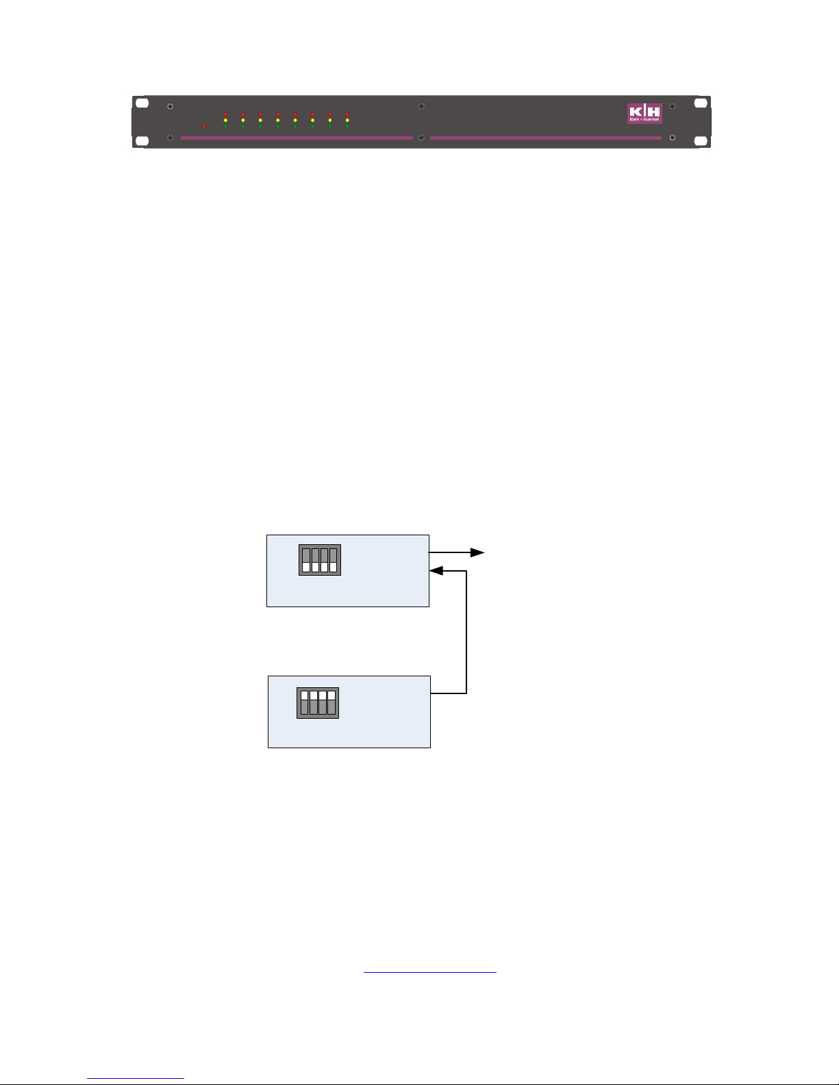
Front Panel Description
Page 9
K8 Rackmount Family User Manual Page 9
0
-20
+12
0
-20
+12
0
-20
+12
0
-20
+12
0
-20
+12
0
-20
+12
0
-20
+12
0
-20
+12
POWER
2 3 4 5 6 7 8
INPUT 1
ANALOGUE LINE INPUT
K8 DIGITAL AUDIO DISTRIBUTION
K8- AI8
K8
K8 K8
K8----AI8 Front Panel
AI8 Front PanelAI8 Front Panel
AI8 Front Panel
Power LED
Power LEDPower LED
Power LED The Power LED is illuminated when the device is plugged in and the rear power
switch is turned on.
Input LEDs
Input LEDsInput LEDs
Input LEDs The red, yellow and green channel Input LEDs show the input signal strength for each
channel downstream of the Cal and DIP switch rear panel level trim adjustments.
Overview
The K8-AI8 is a K8 input device allowing 8 analogue audio channels to be placed onto the K8 bus.
Stacking Input Devices
Two AI8 devices may be stacked to populate all 16 available audio channels. Alternately, the AI8 may be
combined with any other 8 channel input device for a total of 16 channels.
Using a crossover cable connect the Out 2 of the first device to the K8 Out 1 of the second device. The K8
Out 1 of the first device is then used to drive the K8 bus.
K8 Out 1
K8-AI8 Analogue Input
K8 Out 2
K8 Out 1
K8-AI8 Analogue Input
K8 Out 2
Term
On
Not Used
Term
On
Cat 5 Crossover Cable
Out to
Distribution
K8 Channel Inputs 9-16
K8 Channel Inputs 1-8
Termination Setting
The 4 termination switches must all be set to “on” when the AI8 is the first device in the K8 chain.
Both K8 output ports connected: Termination Off
One K8 output port connected: Termination On
Control and Monitoring
All devices on the K8 bus may be controlled and monitored through a single RS-485 connection to the AI8
device. The protocol is openly published on www.klein-hummel.com for use by software engineers and
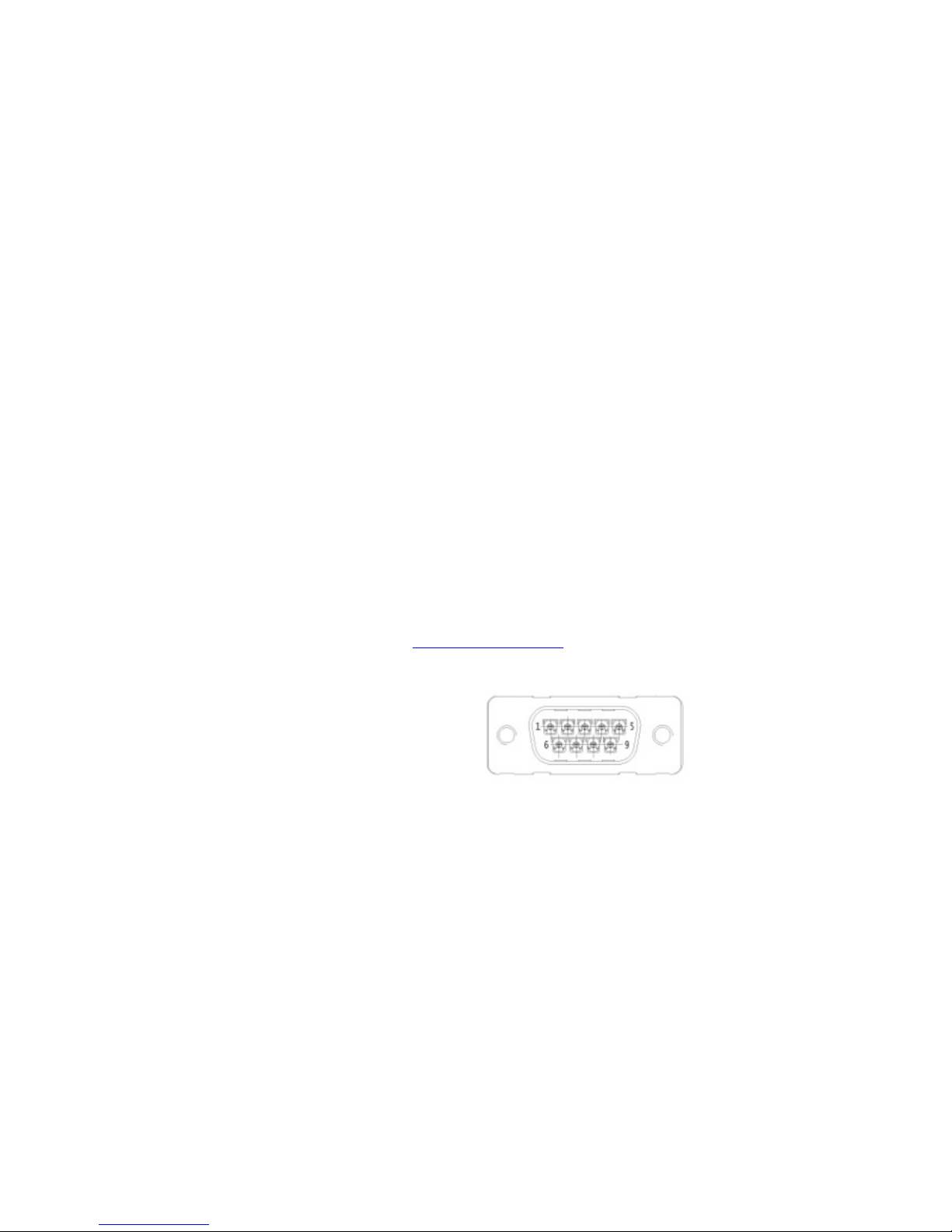
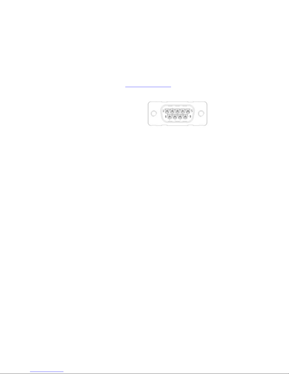
control system programmers. The pinout of the RS-485 port is as follows:
Page 10

Page 10 K8 Rackmount Family User Manual
PIN 1 Phantom Ground
PIN 2 Phantom Power
PIN 3 Data A (+)
PIN 4 Data B (-)
PIN 5 Signal Ground
PIN 6-9 Not Used
The phantom power is used to drive K8 accessories designed to attach to the local control connector, such
as a local volume control wall plate. Phantom power is switched off by default and must be activated
through the control protocol.
Input Level Settings
The AI8 is shipped from the factory to accept a +4 dBu nominal input level with the peaks no greater than
+20 dBu.
For connection of devices with unbalanced RCA connections, such as CD or MP3 players, a rear mounted DIP
switch allows each individual channel to be set to an input level of –10 dBV.
For other input levels less than +20 dBu peak, a recessed screw turn potentiometer can be used to exactly
trim each channel to the desired input level. An overflow LED indicator next to the adjustments shows
when the analogue to digital converter has been saturated.
Front Panel LEDs
Each input channel has 3 front panel LEDs to show channel level. The green LED illuminates at signal
present 32 dB below digital full scale. The yellow LED illuminates at nominal level 12 dB below digital full
scale. The red LED illuminates just before the onset of clipping. Brief illuminations of the red LED are
acceptable in normal operation.
The AI8 input meters show the analogue signal level after it has been adjusted by the DIP switch and
adjustment pot settings, just before it is converted to digital.
Compatible Accessories
K8
K8K8
K8----485
485485
485 USB to RS-485 adaptor cable for using a PC to program K8 system devices.
K8
K8K8
K8----***
******
*** A variety of input and output signal types are available and always growing.
DB9 Female Control Connector
Page 11

K8 Rackmount Family User Manual Page 11
K8-AI8 Technical Specifications
Electrical
Frequency Response
Frequency ResponseFrequency Response
Frequency Response
20 Hz – 22 kHz
Signal to Noise Ratio
Signal to Noise RatioSignal to Noise Ratio
Signal to Noise Ratio
>100dB(A)
Input
InputInput
Input Balanced analogue audio, XLR-1/4” female combo connector x 8
Input Level
Input LevelInput Level
Input Level +22 dBu peak
-10 dbV to +4 dBu nominal input level adjustments
Output
OutputOutput
Output Two K8 bus outputs, each drives 200 meters
Control
ControlControl
Control RS-485, DB-9 female connector, open published protocol
38400 Baud, 8 Data, 1 Stop, No Parity
Optional USB adaptor
Optional Ethernet adaptor
Termination Switch
Termination SwitchTermination Switch
Termination Switch 4-position DIP
Digital Audio Format
Digital Audio FormatDigital Audio Format
Digital Audio Format 48 kHz sampling rate, 24 bit, proprietary
Latency
LatencyLatency
Latency ½ millisecond worst case, analogue in to analogue out
Power Requirements
Power RequirementsPower Requirements
Power Requirements 100 – 240 Volt, 50-60Hz
15 Watts
IEC power cord connector
Front Panel Indicators
Front Panel IndicatorsFront Panel Indicators
Front Panel Indicators Power
Signal present, signal nominal level, signal peak level
Rear Panel Indicators
Rear Panel IndicatorsRear Panel Indicators
Rear Panel Indicators OK, Wink
Mechanical
Weight
WeightWeight
Weight 7 lbs / 3,2kg
Dimensions
DimensionsDimensions
Dimensions EIA Standard 19” Rackmount, 1.75” high, 8 “ deep
Operating Temperature Range
Operating Temperature RangeOperating Temperature Range
Operating Temperature Range 0…70°C
Page 12

Page 12 K8 Rackmount Family User Manual
K8-AO8 Product Manual Section
Rear Panel Description
RS 485
OUTPUT 8
OUTPUT 7OUTPUT 1 OUTPUT 2 OUTPUT 4OUTPUT 3 OUTPUT 5 OUTPUT 6
Wink
TERM
Sync
K8 LINK K8 INPUT
AC IN
100-240V AC, 50-60Hz
Max. Power Consumption 20Watts Made in Germany
K8
K8K8
K8----AO8 Rear Panel
AO8 Rear PanelAO8 Rear Panel
AO8 Rear Panel
Output 1
Output 1Output 1
Output 1----8888 Balanced analogue audio line outputs.
RS 485
RS 485RS 485
RS 485 Remote control connector for PC or external control system connection.
TERM
TERMTERM
TERM DIP switch is used to terminate the device when only one of the two output ports are
being used. The device is terminated when the switch is set to ON. All switches must
be set the same way, either to ON or OFF!
K8 Input
K8 InputK8 Input
K8 Input The K8 signal feed input to the device.
K8 Link
K8 LinkK8 Link
K8 Link A passive loop through connection of the K8 Input for connecting the next device in
the chain.
Sync LED
Sync LEDSync LED
Sync LED The Sync light glows when a K8 Input is connected and locked to the signal coming
from a K8 Input device.
Wink LED
Wink LEDWink LED
Wink LED Light blinks when turned on by remote control software. This light may be used to
confirm that a device is being remote controlled.
Front Panel Description
0
-20
+12
0
-20
+12
0
-20
+12
0
-20
+12
0
-20
+12
0
-20
+12
0
-20
+12
0
-20
+12
POWER
2 3 4 5 6 7 8OUTPUT 1
ANALOGUE LIN E OUTPUT
K8 DIGITAL AUDIO DIST RIBUTION
K8- AO8
K8
K8K8
K8----AO8 Front Panel
AO8 Front PanelAO8 Front Panel
AO8 Front Panel
Power LED
Power LEDPower LED
Power LED The Power LED is illuminated when the device is plugged in and the rear power
switch is turned on.
Output LEDs
Output LEDsOutput LEDs
Output LEDs The red, yellow and green channel Output LEDs show the Output signal level for each
channel at the output XLR connector downstream of the software level trim.
Overview
The K8-AO8 is a K8 output device for receiving 8 audio channels from the K8 bus and decoding them into 8
analogue outputs.
Page 13
K8 Rackmount Family User Manual Page 13
Routing Capabilities
As shipped from the factory, the K8-AO8 will place audio channels 1-8 on outputs 1-8.
The K8 bus contains 16 audio channels, in two groups of 8. The K8 terminal control protocol is capable of
configuring the K8-AO8 to select either the group of channels numbered 1-8 or the group of channels
numbered 9-16 for output. Channel 1 appears on output 1, channel 2 on output 2 and so forth. When
selecting the second group of channels, channel 9 appears on output 1, channel 10 appears on output 2
and so forth.
The first two outputs of the AO8 device can select any stereo pair within the group of channels being
received.
Stacking Output Devices
The K8 bus supports a maximum quantity of 254 devices. Output devices may be daisy chained until the
maximum cable length of 200 meters has been reached. Output devices are passively connected and do
not refresh the K8 audio signal. This architecture has the benefit that a failure of an output device will still
allow audio to pass to the next device in the chain. Daisy chaining devices introduces no delay in the audio
signal.
Termination Setting
All 4 termination switches must be set to “on” when the AO8 is the last device in the K8 chain.
K8 link port connected: Termination Off
K8 link port not connected: Termination On
Control and Monitoring
All devices on the K8 bus may be controlled and monitored through a single RS-485 connection to the AI8
device. The protocol is openly published on www.klein-hummel.com for use by software engineers and
control system programmers. The pinout of the RS-485 port is as follows:
PIN 1 Phantom Ground
PIN 2 Phantom Power
PIN 3 Data A (+)
PIN 4 Data B (-)
PIN 5 Signal Ground
PIN 6-9 Not Used
A limited amount of serial data tunnelling is available between the serial ports on any two devices in the
system. This is useful for passing control data to another system, such as a lighting controller or external
relay box located in the same equipment area as the K8 output box.
The phantom power is used to drive K8 accessories designed to attach to the local control connector, such
as a local volume control wall plate. Phantom power is switched off by default and must be activated
through the control protocol.
Output Level Settings
The AO8 is shipped from the factory to provide a +4 dBu nominal output level with a peak level of +22
dBu. By default, the same signal level fed into an analogue input AI8 will appear at an analogue output
AO8 at the same level.
The output level of an AO8 may be trimmed down to any lower value by using the K8 terminal control
protocol.
DB9 Female Control Connector
Page 14

Page 14 K8 Rackmount Family User Manual
Front Panel LEDs
Each input channel has 3 front panel LEDs to show channel level. The green LED illuminates at signal
present 32 dB below digital full scale. The yellow LED illuminates at nominal level 12 dB below digital full
scale. The red LED illuminates just before the onset of clipping. Brief illuminations of the red LED are
acceptable in normal operation.
The AO8 output meters show the analogue signal level after it has been attenuated by the output level
trims settable in software. This is an indication of the audio level at the analogue audio output connector
of the unit.
Compatible Accessories
K8
K8K8
K8----485
485485
485 USB to RS-485 adaptor cable for using a PC to program K8 system devices.
K8
K8K8
K8----***
******
*** A variety of input and output signal types are available and always growing.
Page 15

K8 Rackmount Family User Manual Page 15
K8-AO8 Technical Specifications
Electrical
Frequency Response
Frequency ResponseFrequency Response
Frequency Response
20 Hz – 22 kHz
Signal to Noise Ratio
Signal to Noise RatioSignal to Noise Ratio
Signal to Noise Ratio
>100dB(A)
Input
InputInput
Input K8 digital audio bus, RJ-45
Output
OutputOutput
Output 8 x analogue audio out, XLR male connectors
Output Level
Output LevelOutput Level
Output Level +22 dBu peak, software adjustable attenuation
Control
ControlControl
Control RS-485, DB-9 female connector, open published protocol
38400 Baud, 8 Data, 1 Stop, No Parity
Optional USB adaptor etc.
Termination Switch
Termination SwitchTermination Switch
Termination Switch 4-position DIP
Digital Audio Format
Digital Audio FormatDigital Audio Format
Digital Audio Format 48 kHz sampling rate, 24 bit, proprietary
Latency
LatencyLatency
Latency ½ millisecond worst case, analogue in to analogue out
Power Requirements
Power RequirementsPower Requirements
Power Requirements 100 – 240 Volt, 50-60Hz
20 Watts
IEC power cord connector
Front Panel Indicators
Front Panel IndicatorsFront Panel Indicators
Front Panel Indicators Power
Signal present, signal nominal level, signal peak level
Rear Panel Indicators
Rear Panel IndicatorsRear Panel Indicators
Rear Panel Indicators Sync, wink
Mechanical
Weight
WeightWeight
Weight 7 lbs / 3.2 kg
Dimensions
DimensionsDimensions
Dimensions EIA Standard 19” Rackmount, 1.75” high, 8“ deep
Operating Temperature Range
Operating Temperature RangeOperating Temperature Range
Operating Temperature Range 0…70°C
Page 16
Page 16 K8 Rackmount Family User Manual
K8-AO2 Product Manual Section
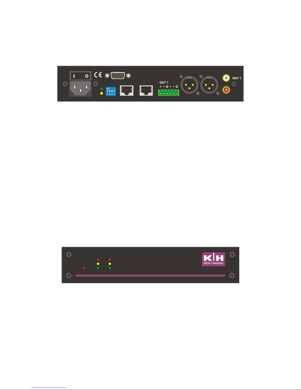
Rear Panel Description
Max. Power Consumption 10Watts
RS 485
AC IN: 100-240V AC, 50-60Hz
OUTPUT 1 OUTPUT 2
OUT 2
OUT 2
K8 LINK
K8 INPUT
TERM
S
W
Made in Germany
K8
K8K8
K8----AO2 Rear Panel
AO2 Rear PanelAO2 Rear Panel
AO2 Rear Panel
Output 1
Output 1Output 1
Output 1----2222 Balanced analogue audio line outputs, unbalanced line outputs on RCA cinch.
RS 485
RS 485RS 485
RS 485 Remote control connector for PC or external control system connection.
TERM
TERMTERM
TERM DIP switch is used to terminate the device when only one of the two output ports are
being used. The device is terminated when the switch is set to ON. All switches must
be set the same way, either to ON or OFF!
K8 Input
K8 InputK8 Input
K8 Input The K8 signal feed input to the device.
K8 Link
K8 LinkK8 Link
K8 Link A passive loop through connection of the K8 Input for connecting the next device in
the chain.
Sync LED
Sync LEDSync LED
Sync LED The Sync light glows when a K8 Input is connected and locked to the signal coming
from a K8 Input device.
Win
WinWin
Wink LED
k LEDk LED
k LED Light blinks when turned on by remote control software. This light may be used to
confirm that a device is being remote controlled.
Front Panel Description
ANALOGUE LINE OUTPUT
K8 DIGITAL AUDIO DISTRIBUTION
0
-20
+12
0
-20
+12
POWER
2
OUTPUT 1
K8- AO2
K8
K8K8
K8----AO2 Front Panel
AO2 Front PanelAO2 Front Panel
AO2 Front Panel
Power LED
Power LEDPower LED
Power LED The Power LED is illuminated when the device is plugged in and the rear power
switch is turned on.
Output LEDs
Output LEDsOutput LEDs
Output LEDs The red, yellow and green channel Output LEDs show the Output signal level for each
channel at the output connector downstream of the software level trim.
Page 17
K8 Rackmount Family User Manual Page 17
Overview
The K8-AO2 is a K8 output device for receiving 2 audio channels from the K8 bus and decoding them into 2
analogue outputs.
Routing Capabilities
As shipped from the factory, the K8-AO2 will place audio channels 1,2 on outputs 1,2.
The two outputs of the AO2 device can select any stereo pair from the K8 bus. A stereo pair must be
adjacent channels and begin with an odd numbered channel. For example, channels 1 and 2, 3 and 4, 5
and 6 and so forth are all valid.
Stacking Output Devices
The K8 bus supports a maximum quantity of 254 devices. Output devices may be daisy chained until the
maximum cable length of 200 meters has been reached. Output devices are passively connected and do
not refresh the K8 audio signal. This architecture has the benefit that a failure of an output device will still
allow audio to pass to the next device in the chain. Daisy chaining devices introduces no delay in the audio
signal.
Termination Setting
All 4 termination switches must be set to “on” when the AO2 is the last device in the K8 chain.
K8 link port connected: Termination Off
K8 link port not connected: Termination On
Control and Monitoring
All devices on the K8 bus may be controlled and monitored through a single RS-485 connection to the AI8
device. The protocol is openly published on www.klein-hummel.com for use by software engineers and
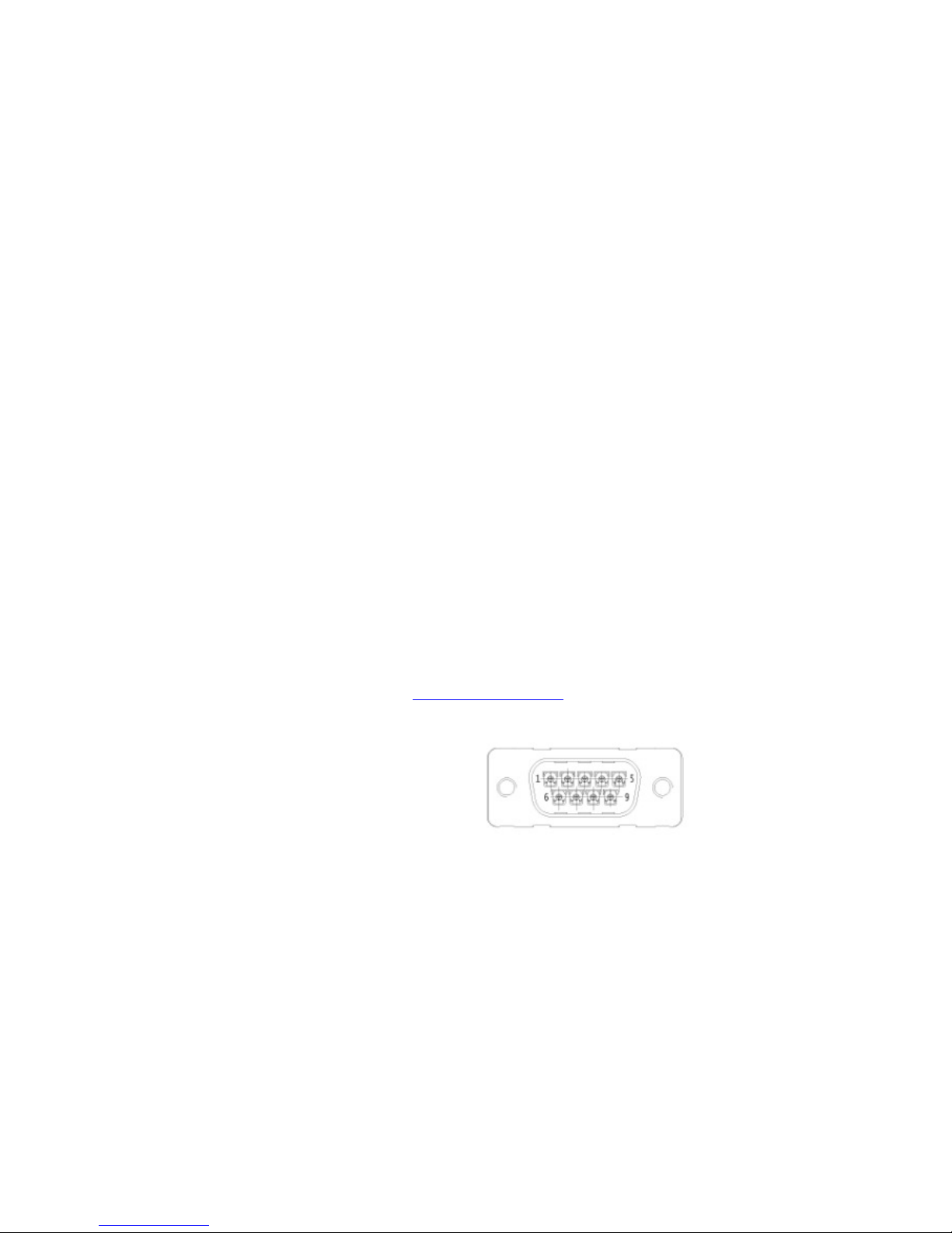
control system programmers. The pinout of the RS-485 port is as follows:
PIN 1 Phantom Ground
PIN 2 Phantom Power
PIN 3 Data A (+)
PIN 4 Data B (-)
PIN 5 Signal Ground
PIN 6-9 Not Used
A limited amount of serial data tunnelling is available between the serial ports on any two devices in the
system. This is useful for passing control data to another system, such as a lighting controller or external
relay box located in the same equipment area as the K8 output box.
The phantom power is used to drive K8 accessories designed to attach to the local control connector, such
as a local volume control wall plate. Phantom power is switched off by default and must be activated
through the control protocol.
Output Level Settings
The AO2 is shipped from the factory to provide a +4 dBu nominal output level with a peak level of +22 dBu
on the XLR and terminal block connectors. By default, the same signal level fed into an analogue input AI8
will appear at an analogue output AO2 at the same level.
The RCA cinch connectors are factory set to provide a –10 dBV nominal output level.
DB9 Female Control Connector
Page 18

Page 18 K8 Rackmount Family User Manual
The output levels of an AO2 may be trimmed down to any lower value by using the K8 terminal control
protocol.
Front Panel LEDs
Each input channel has 3 front panel LEDs to show channel level. The green LED illuminates at signal
present 32 dB below digital full scale. The yellow LED illuminates at nominal level 12 dB below digital full
scale. The red LED illuminates just before the onset of clipping. Brief illuminations of the red LED are
acceptable in normal operation.
The AO2 output meters show the analogue signal level after it has been attenuated by the output level
trims settable in software. This is an indication of the audio level at the analogue audio output connector
of the unit.
Compatible Accessories
K8
K8K8
K8----485
485485
485 USB to RS-485 adaptor cable for using a PC to program K8 system devices.
K8
K8K8
K8----***
******
*** A variety of input and output signal types are available and always growing.
K8
K8K8
K8----RMK
RMKRMK
RMK Half rack mounting kit, accepts up to two devices.
K8
K8K8
K8----FMK
FMKFMK
FMK Flange mounting kit for mounting the device under tables, etc.
Page 19

K8 Rackmount Family User Manual Page 19
K8-AO2 Technical Specifications
Electrical
Frequency Respo
Frequency RespoFrequency Respo
Frequency Response
nsense
nse
20 Hz – 22 kHz
Signal to Noise Ratio
Signal to Noise RatioSignal to Noise Ratio
Signal to Noise Ratio
>100dB(A)
Input
InputInput
Input K8 digital audio bus, RJ-45
Output
OutputOutput
Output 2 x analogue audio out, XLR male connectors , RCA cinch connectors and
removable terminal blocks in parallel
Output Level
Output LevelOutput Level
Output Level +22 dBu peak on XLR and terminals, software adjustable attenuation
+10 dBu peak (nominal –10 dBV) on RCA cinch connectors
Control
ControlControl
Control RS-485, DB-9 female connector, open published protocol
38400 Baud, 8 Data, 1 Stop, No Parity
Optional USB adaptor etc.
Termination Switch
Termination SwitchTermination Switch
Termination Switch 4-position DIP
Digital A
Digital ADigital A
Digital Audio Format
udio Formatudio Format
udio Format 48 kHz sampling rate, 24 bit, proprietary
Latency
LatencyLatency
Latency ½ millisecond worst case, analogue in to analogue out
Power Requirements
Power RequirementsPower Requirements
Power Requirements 95 - 240 Volts AC (±10%), 50 - 60 Hz, wide range power supply
10 Watts
IEC power cord connector
Front Panel Indicators
Front Panel IndicatorsFront Panel Indicators
Front Panel Indicators Power
Signal present, signal nominal level, signal peak level
Rear Panel Indicators
Rear Panel IndicatorsRear Panel Indicators
Rear Panel Indicators Sync, wink
Mechanical
Weight
WeightWeight
Weight 4.4 lbs / 2 kg
Dimensions
DimensionsDimensions
Dimensions 9.5” wide , 1.75” high, 8“ deep
Operating Temperature Range
Operating Temperature RangeOperating Temperature Range
Operating Temperature Range 0…70°C (32…160°F)
Page 20
Page 20 K8 Rackmount Family User Manual
K8-ESB Product Manual Section
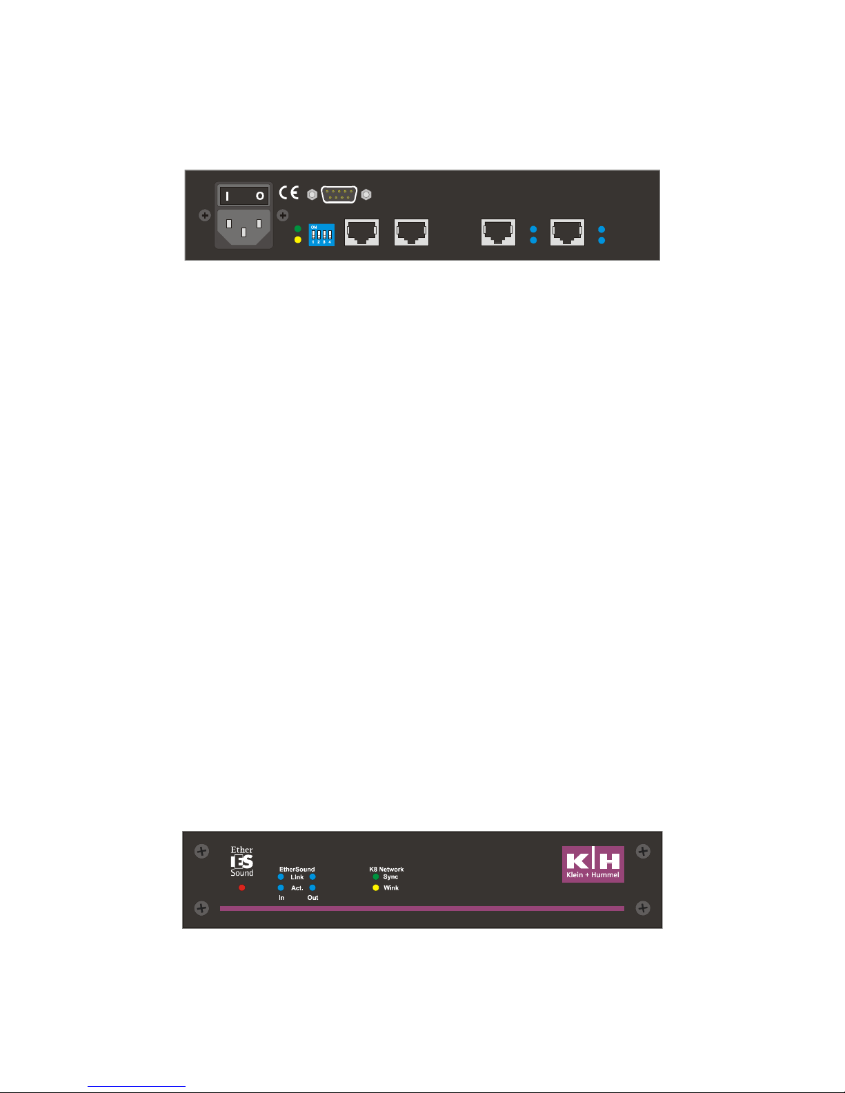
Rear Panel Description
Max. Power Consumption 20Watts
RS 485
AC IN: 100-240V AC, 50-60Hz
CONFIG
S
W
Made in Germany
21 K8 OUT
EtherSound Network
IN
OUT
Link
Activity
K8
K8K8
K8----ESB Rear Panel
ESB Rear PanelESB Rear Panel
ESB Rear Panel
RS 485
RS 485RS 485
RS 485 Remote control connector for PC or external control system connection.
CONFIG
CONFIGCONFIG
CONFIG The first three DIP switch positions are used to terminate the device when only one
of the two output ports are being used. The device is terminated when the switch is
set to ON. Switches 1,2, 3 must be set the same way, either to ON or OFF!
The 4th DIP switch selects between 8 and 16 channel mode. ON is 8 channels. OFF is
16 channels.
K8 OUT
K8 OUT K8 OUT
K8 OUT 1 and 2
1 and 21 and 2
1 and 2 K8 digital audio bus outputs. Each one contains the same audio and control data and
each one is capable of driving a 200 meter line. When only one output is used the
termination switch must be set to ON.
Sync LED
Sync LEDSync LED
Sync LED The Sync light glows when an EtherSound network is connected and locked.
Wink LED
Wink LEDWink LED
Wink LED Light blinks when turned on by remote control software. This light may be used to
confirm that a device is being remote controlled.
EtherSound IN
EtherSound INEtherSound IN
EtherSound IN Used to connect to an upstream device of an EtherSound network according the
EtherSound standards.
EtherSound OUT
EtherSound OUTEtherSound OUT
EtherSound OUT Used to connect to a downstream device of an EtherSound network according the
EtherSound standards.
EtherSound Link LED
EtherSound Link LEDEtherSound Link LED
EtherSound Link LED Indicates that a valid EtherSound device is connected to the K8-ESB and is
synchronized.
EtherSound Activity
EtherSound ActivityEtherSound Activity
EtherSound Activity Indicates communication activity to the connected EtherSound device.
LED
LEDLED
LED
Front Panel Description
ETHERSOUND BREAKOUT
K8 DIGITAL AUDIO DISTRIBUTION
POWER
K8- ESB
K8
K8K8
K8----ESB Front Panel
ESB Front PanelESB Front Panel
ESB Front Panel
Power LED
Power LEDPower LED
Power LED The Power LED is illuminated when the device is plugged in and the rear power
switch is turned on.
Page 21

K8 Rackmount Family User Manual Page 21
Sync LED
Sync LEDSync LED
Sync LED The Sync light glows when an EtherSound network is connected and locked.
Wink LED
Wink LEDWink LED
Wink LED Light blinks when turned on by remote control software. This light may be used to
confirm that a device is being remote controlled.
EtherSound Link LED
EtherSound Link LEDEtherSound Link LED
EtherSound Link LED Indicates that a valid EtherSound device is connected to the K8-ESB and is
synchronized.
EtherSound Activity
EtherSound ActivityEtherSound Activity
EtherSound Activity Indicates communication activity to the connected EtherSound device.
LED
Overview
The K8-ESB is used for routing any available EtherSound audio channel onto any one of 16 channels on the
K8 digital distribution bus.
Rack Mounting
The K8-ESB requires the optional accessory K8-RMK rack mounting kit. Two units may be mounted side by
side.
Routing Capabilities
The K8 bus contains 16 audio channels, in two groups of 8. The software utility, EtherSound Monitor,
available from Auvitran.com, or any other EtherSound standard control program may be used to select
which of the available EtherSound channels are routed onto the K8 bus.
Stacking Input Devices
It is also possible to turn off 8 channels of a 16 channel device, such as the K8-ESB, and combine it with 8
channels of another audio input type, such as the K8-AI8 analog inputs.
The 4th CONFIG DIP switch on the K8-ESB is used to turn off transmission of channels 9-16, making it
function like any other 8 channel K8 input device.
Using a crossover cable connect the Out 2 of the first device to the K8 Out 1 of the second device. The K8
Out 1 of the first device is then used to drive the K8 bus.
K8 Out 1
K8-ESB Ethersound Bridge
K8 Out 2
K8 Out 1
K8-AI8 Analogue Input
K8 Out 2
CONFIG
On
Not Used
TERM
On
Cat 5 Crossover Cable
Out to
Distribution
K8 Channel Inputs 9-16
K8 Channel Inputs 1-8
K8 Out 1
K8-AI8 Analogue Input
K8 Out 2
K8 Out 1
K8-ESB EtherSound Bridge
K8 Out 2
TERM
On
Not Used
CONFIG
On
Cat 5 Crossover Cable
Out to
Distribution
K8 Channel Inputs 9-16
K8 Channel Inputs 1-8
Page 22
Page 22 K8 Rackmount Family User Manual
Termination Setting
The first 3 configuration DIP switches must be set to “on” when the ESB is the last device in the K8 chain.
K8 link port connected: Termination Off
K8 link port not connected: Termination On
Control and Monitoring
All devices on the K8 bus may be controlled and monitored through a single RS-485 connection to the ESB
device. The protocol is openly published on www.klein-hummel.com for use by software engineers and
control system programmers. The pinout of the RS-485 port is as follows:
PIN 1 Phantom Ground
PIN 2 Phantom Power
PIN 3 Data A (+)
PIN 4 Data B (-)
PIN 5 Signal Ground
PIN 6-9 Not Used
A limited amount of serial data tunnelling is available between the serial ports on any two devices in the
system. This is useful for passing control data to another system, such as a lighting controller or external
relay box located in the same equipment area as the K8 output box.
The phantom power is used to drive K8 accessories designed to attach to the local control connector, such
as a local volume control wall plate. Phantom power is switched off by default and must be activated
through the control protocol.
Compatible Accessories
K8
K8K8
K8----485
485485
485 USB to RS-485 adaptor cable for using a PC to program K8 system devices.
K8
K8K8
K8----***
******
*** A variety of input and output signal types are available and always growing.
K8
K8K8
K8----RMK
RMKRMK
RMK Half rack mounting kit, accepts up to two devices.
K8
K8K8
K8----FMK
FMKFMK
FMK Flange mounting kit for mounting the device under tables, etc.
DB9 Female Control Connector
Page 23

K8 Rackmount Family User Manual Page 23
K8-ESB Technical Specifications
Electrical
Frequency Response
Frequency ResponseFrequency Response
Frequency Response
20 Hz – 22 kHz
Input
InputInput
Input EtherSound ES100, IN and OUT
Output
OutputOutput
Output Two K8 bus outputs, each drives 200 meters
Control
ControlControl
Control RS-485, DB-9 female connector, open published protocol
38400 Baud, 8 Data, 1 Stop, No Parity
Optional USB adaptor etc.
Configuration Switch
Configuration SwitchConfiguration Switch
Configuration Switch 4-position DIP
Digital Audio
Digital Audio Digital Audio
Digital Audio Format
FormatFormat
Format 48 kHz sampling rate, 24 bit, proprietary
Latency
LatencyLatency
Latency 1-½ millisecond worst case, dependent on EtherSound network design
Power Requirements
Power RequirementsPower Requirements
Power Requirements 95 - 240 Volts AC (±10%), 50 - 60 Hz, wide range power supply
15 Watts
IEC power cord and connector
Front Pan
Front PanFront Pan
Front Panel Indicators
el Indicatorsel Indicators
el Indicators Power
Sync, wink, ES IN link/activity, ES OUT link/activity
Rear Panel Indicators
Rear Panel IndicatorsRear Panel Indicators
Rear Panel Indicators Sync, wink, ES IN link/activity, ES OUT link/activity
Mechanical
Weight
WeightWeight
Weight 4.4 lbs / 2 kg
Dimensions
DimensionsDimensions
Dimensions 9.5” wide , 1.75” high, 8“ deep
Operating Temperature Ran
Operating Temperature RanOperating Temperature Ran
Operating Temperature Range
gege
ge 0…70°C (32…160°F)
Page 24

Page 24 K8 Rackmount Family User Manual
Notes
Page 25

Manuel Utilisateur
K8-AI8 K8-AO2
K8-AO8 K8-ESB
K8
Digital Audio Distribution System
Page 26

Page
26
Manuel Utilisateur Famille Produits K8
Instructions de sécurité
Il est absolument essentiel de lire avec attention ces instructions de sécurité avant de brancher et
d’utiliser ce produit K+H. Votre sécurité en dépend. La garantie du produit est annulée si vous ne
suivez pas ces instructions.
Afin d’assurer un fonctionnement sans problème pendant des années, conservez ce manuel utilisateur en lieu sûr, afin de
pouvoir vous y référer facilement à l’avenir. K+H a fabriqué ce produit en conformité avec les standards IEC 92 (SEC) 39, avant
de les tester et de les livrer en bon état de fonctionnement. Pour obtenir des performances optimales avec ce produit :
•
Conformez-vous à toutes les instructions de sécurité ;
•
N’utilisez le produit que dans les conditions décrites dans ce manuel
•
Ne faites effectuer la maintenance, les réparations ou les modifications que par des techniciens agréés par K+H
•
Vérifiez que le local dans lequel vous désirez utiliser ce produit est câblé conformément aux normes électriques locales
Attention
AttentionAttention
Attention !!!!
•
Lorsque l’intérieur du coffret est exposé, toucher certaines parties peut provoquer une électrocution.
•
Si vous désirez accéder aux circuits électroniques internes de l’appareil, commencez toujours par le débrancher
de ses sources d’alimentation.
•
Toute réparation, maintenance, ou autre tâche à effectuer alors que l’appareil est ouvert, et donc son
compartiment intérieur accessible, ne peut être assurée en toute sécurité (conformément à VBG 4) que par des
techniciens habilités, maîtrisant les risques encourus. L’électrocution est possible même si l’appareil n’est pas
relié au secteur.
Fig. A
•
Si vous devez remplacer un fusible, vérifiez que le modèle de rechange est exactement du même type, calibre et
tension que l’original – au moindre doute, reportez-vous aux caractéristiques techniques de l’appareil, à la fin de
ce manuel.
•
N’utilisez pas de fusible "réparé".
•
Si vous ne disposez pas de fusible de rechange des dimensions, du type ou de la valeur spécifiés, ne courtcircuitez pas les extrémités du fusible défectueux avec un fil conducteur.
•
Certaines parties du coffret, du capot ou du panneau arrière de l’appareil peuvent atteindre des températures
très élevées : elles sont repérées par l’apposition du logo "HOT" (Fig. B). Évitez de toucher les radiateurs et les
grilles de ventilation.
•
Il est prouvé que les niveaux sonores élevés provoquent des dommages auditifs définitifs et irréversibles,
surtout si on écoute de façon continue, sans pause. Plus le niveau sonore est élevé, plus les pauses doivent être
fréquentes et longues. Évitez de rester trop longtemps à proximité immédiate des enceintes utilisées à fort
niveau. Si vous devez vous exposer à des niveaux sonores élevés pendant une longue durée, portez des
protections auditives (casque antibruit, bouchons d’oreille…).
Fig. B
Branchement secteur :
Branchement secteur :Branchement secteur :
Branchement secteur :
•
Cet appareil est conçu pour fonctionner en permanence.
•
Vérifiez que la tension de fonctionnement de l’appareil correspond à celle délivrée par le secteur local.
•
Avant de relier le câble secteur à la prise murale, vérifiez toujours que l’interrupteur est réglé sur Off ("O") sur l’appareil
lui-même.
•
N’utilisez que le câble secteur ou l’alimentation livrée avec l’appareil pour le brancher sur le secteur (prise murale).
•
N’essayez jamais de réparer un câble secteur endommagé. Utilisez un nouveau câble.
•
Évitez de brancher le câble secteur dans une prise alimentant déjà plusieurs autres appareils gourmands en électricité.
•
Évitez d’utiliser des rallonges. Mieux vaut brancher l’appareil sur une prise secteur située à proximité, facilement
accessible.
Installation :
Installation :Installation :
Installation :
•
L’installation, et l’éventuelle suspension de ce produit doit être effectuée par un professionnel qualifié, en respectant les
codes et standards locaux, nationaux et internationaux. Les dispositifs de montage livrés par le fabricant doivent être
fixés aux points appropriés et au matériel approprié, conçu et évalué pour une telle utilisation.
•
N’exposez pas ce produit aux vibrations.
•
N’utilisez pas ce produit à proximité d’eau ou d’autres liquides. Ne l’utilisez pas à proximité d’un évier, d’une piscine,
d’un lavabo, d’une douche ou de tout local ou zone humide. Les chocs électriques transportés par l’eau peuvent être
mortels. Ne placez pas de boissons au-dessus ni à proximité de cet appareil – les liquides peuvent détruire les
composants électroniques.
•
Assurez une ventilation suffisante autour du produit, afin de permettre une dissipation thermique suffisante –
notamment en ce qui concerne le panneau arrière et les côtés du coffret (20 cm au minimum par rapport au mur le plus
proche). N’installez l’appareil dans un rack que si sa ventilation est assurée, et en vous conformant aux instructions de
montage données par le fabricant. N’obstruez pas les radiateurs, les ventilateurs ou les ouïes d’aération.
•
Laissez ce produit à une distance raisonnable des radiateurs et autres sources de chaleur de toutes sortes.
•
Si vous faites passer ce produit d’un environnement froid à un environnement chaud, il est possible que de la
condensation apparaisse à l’intérieur du coffret. Avant de brancher et d’utiliser ce produit, laissez-lui le temps (30
minutes ou davantage) de se mettre à température ambiante.
•
Pour éviter les accidents, n’utilisez avec ce produit aucun accessoire non approuvé par le fabricant – en particulier, des
accessoires de montage.
•
Ne placez pas cet appareil sur un support instable (plate-forme, chariot, pied, table…). Si l’appareil tombe, il peut
provoquer des blessures corporelles ou être endommagé.
•
Pour protéger ce produit de la foudre en cas d’orage ou en cas de surtension électrique en cas d’absence prolongée,
veuillez débrancher son câble d’alimentation de la prise secteur.
Page 27

Manuel Utilisateur Famille Produits K8 Page 27
Sommaire
Instructions de sécurité 26
MANUEL UTILISATEUR DE LA FAMILLE DE PRODUITS K8 29
Présentation générale de la gamme K8 ..................................................................................................... 29
Prise en main................................................................................................................................................... 29
Utilisation des modules d’entrée................................................................................................................. 29
Utilisation des modules de sortie ................................................................................................................ 29
Connexion d’un système de contrôle .......................................................................................................... 30
Surveillance du système via un PC .............................................................................................................. 30
Code couleur du câble Cat5 ........................................................................................................................... 30
Foire Aux Questions (FAQ)............................................................................................................................ 30
Déclarations du fabricant 32
Déclaration de conformité pour la CEE........................................................................................................32
SECTION SPÉCIFIQUE AU MODULE K8-AI8 33
Description du panneau arrière ................................................................................................................... 33
Description de la face avant ......................................................................................................................... 34
Présentation générale ................................................................................................................................... 34
Chaînage des modules d’entrée ................................................................................................................... 34
Réglage des terminaisons ............................................................................................................................. 34
Contrôle et surveillance à distance du système........................................................................................ 35
Réglage des niveaux d’entrée ...................................................................................................................... 35
LED en face avant ........................................................................................................................................... 35
Accessoires compatibles................................................................................................................................ 35
Caractéristiques techniques du module K8-AI8........................................................................................ 36
Caractéristiques électriques........................................................................................................................... 36
Caractéristiques mécaniques......................................................................................................................... 36
SECTION SPÉCIFIQUE AU MODULE K8-AO8 37
Description du panneau arrière ................................................................................................................... 37
Description de la face avant ......................................................................................................................... 37
Présentation générale ................................................................................................................................... 37
Possibilités d’assignation (routing)............................................................................................................ 38
Chaînage de périphériques de sortie........................................................................................................... 38
Réglage des terminaisons ............................................................................................................................. 38
Contrôle et surveillance à distance du système........................................................................................ 38
Réglage des niveaux de sortie...................................................................................................................... 38
LED en face avant ........................................................................................................................................... 39
Accessoires compatibles................................................................................................................................ 39
Caractéristiques techniques du module K8-AO8 ...................................................................................... 40
Caractéristiques électriques........................................................................................................................... 40
Caractéristiques mécaniques......................................................................................................................... 40
Page 28

Page 28 Manuel Utilisateur Famille Produits K8
SECTION SPÉCIFIQUE AU MODULE K8-AO2 41
Description du panneau arrière ................................................................................................................... 41
Description de la face avant ......................................................................................................................... 41
Présentation générale ................................................................................................................................... 42
Possibilités d’assignation (routing)............................................................................................................ 42
Chaînage de périphériques de sortie........................................................................................................... 42
Réglage des terminaisons ............................................................................................................................. 42
Contrôle et surveillance à distance du système........................................................................................ 42
Réglage des niveaux de sortie...................................................................................................................... 42
LED en face avant ........................................................................................................................................... 43
Accessoires compatibles................................................................................................................................ 43
Caractéristiques techniques du module K8-AO2 ...................................................................................... 44
Caractéristiques électriques........................................................................................................................... 44
Caractéristiques mécaniques......................................................................................................................... 44
SECTION SPÉCIFIQUE AU MODULE K8-ESB 45
Description du panneau arrière ................................................................................................................... 45
Description de la face avant ......................................................................................................................... 46
Présentation générale ................................................................................................................................... 46
Mountage en rack........................................................................................................................................... 46
Fonctions d’assignation ................................................................................................................................ 46
Cumul de modules d’entrée .......................................................................................................................... 46
Réglage de terminaison.................................................................................................................................47
Contrôle et surveillance à distance du système........................................................................................ 47
Accessoires compatibles................................................................................................................................ 47
Caractéristiques techniques du module K8-ESB ....................................................................................... 48
Caractéristiques électriques........................................................................................................................... 48
Caractéristiques mécaniques......................................................................................................................... 48
Page 29

Manuel Utilisateur Famille Produits K8 Page 29
MANUEL UTILISATEUR DE LA FAMILLE DE PRODUITS K8
Commencez par lire attentivement cette section : elle expose la théorie système globale sur laquelle
s’appuient tous les appareils de la famille de produits K8. Vous trouverez dans d’autres sections de ce
manuel les détails concernant telle ou telle référence (AI8, AO8).
Présentation générale de la gamme K8
Le K8 est un système numérique de distribution audio. Il permet de transporter 16 signaux
audionumériques sur un simple câble de type Cat 5, en même temps que les données de contrôle. Les
signaux audio ne circulent que dans un seul sens, de l’appareil d’entrée vers l’appareil de sortie. Les
signaux de contrôle, eux, sont bidirectionnels.
Prise en main
Les modules K8 sont configurés en usine de façon à laisser passer les signaux audio immédiatement après
mise sous tension. L’assignation est alors simple : les 8 canaux d’entrée sont envoyés aux 8 canaux de
sortie. Des paramétrages et configurations plus complexes sont possibles si désiré, en utilisant le protocole
de contrôle de terminal K8. C’est via ce protocole que vous pouvez, par exemple, configurer un module K8
de sortie 8 canaux de façon à ce qu’il sélectionne les canaux 9 à 16 au lieu des canaux 1 à 8.
Utilisation des modules d’entrée
Les modules d’entrée servent à envoyer des données audio sur le bus K8 ; les modules de sortie servent à
en extraire des données audio.
En chaînant (‘stack’) deux modules 8 canaux, vous arrivez à la capacité maximale disponible sur un câble
(bus) K8, soit 16 canaux. Par exemple, avec deux modules AI8, vous injectez 16 signaux d’entrée
analogiques sur le bus numérique K8.
Pour chaîner (‘stack’) deux modules, il suffit de relier le bus de sortie K8 Out 2 du premier module à la
sortie K8 Out 1 du second. Il ne reste alors plus qu’à relier la sortie K8 Out 1 du premier module au bus K8.
K8 Out 1
K8 Out 2
K8 Out 1
Module d'entrée analogique K8-AI8
K8 Out 2
Term
On
Non utilisé
Term
On
Câble Cat5 croisé
Sortie vers distribution
Canaux d'entrée K8 9 à 16
Canaux d'entrée 1 à 8
Module d'entrée analogique K8-AI8
Utilisation des modules de sortie
RÈGLE DE LA TERMINAISON : Le premier et le dernier périphérique d’une chaîne K8 doivent avoir leurs
sélecteurs de terminaison activés. Si les deux ports K8 d’un module sont utilisés, ses 4 sélecteurs se
Page 30

Page 30 Manuel Utilisateur Famille Produits K8
trouvent en position On. Si l’un des ports K8 d’un module n’est pas connecté, les 4 sélecteurs sont en
position Off. Le protocole de contrôle des terminaux K8 est capable de vérifier à distance les positions des
sélecteurs de terminaison.
Les modules d’entrée servent à injecter les signaux audio sur le bus K8 ; les modules de sortie servent à
extraire les signaux audio du bus K8.
Vous pouvez cascader les modules de sortie (« daisy chain ») jusqu’à atteindre une longueur maximale de
200 mètres. Les modules de sortie sont connectés de façon passive, et ne « rafraîchissent » pas le signal
audio transporté par le bus K8 (pas de remise en forme). Pourquoi avoir adopté cette architecture ? Parce
qu’en cas de défaillance d’un module de sortie, le signal du bus K8 continue à passer, en direction du
module suivant dans la chaîne. Les appareils ainsi cascadés n’introduisent aucun retard dans le signal
audio.
Connexion d’un système de contrôle
Vous pouvez visualiser et contrôler les statuts de tous les modules K8 d’un système, via le port RS-485
équipant le module d’entrée. Le signal de contrôle passe par le même câble que les signaux audio, et ne
demande aucun aménagement spécifique. Le protocole est ouvert, et publié sur notre site Web,
www.klein-hummel.com, pour une utilisation libre par les ingénieurs logiciels et les programmeurs de
systèmes de contrôle.
Surveillance du système via un PC
Vous pouvez surveiller et contrôler les modules d’un système K8 en utilisant un logiciel « terminal »
traitant les informations contenues dans le protocole de contrôle par terminal K8. Vous trouverez des
instructions sur son utilisation (en anglais) sur notre site Web, www.klein-hummel.com.
Certains modules K8 sont connectés au PC par l’intermédiaire d’un port RS-485, d’autres via un port
Ethernet. Il est possible d’acheter des adaptateurs USB/485 adapter. Veuillez vous référer à la section de ce
manuel traitant de ce module spécifique.
Code couleur du câble Cat5
Le système K8 utilise le même câblage et la même assignation des contacts que le protocole Ethernet –
même si le protocole K8 n’est PAS un protocole Ethernet.
Les câbles utilisés dans un système K8 doivent posséder une terminaison conforme aux standards TIA/EIA568A ou TIA/EIA-568B. Ces deux standards créent un câble « droit » lorsque vous utilisez le même code
couleur aux deux extrémités du câble. Pour créer un câble croisé, il faut terminer une extrémité en 568A et
terminer l’autre en 568B.
Foire Aux Questions (FAQ)
Qu’est
Qu’estQu’est
Qu’est----ce que le «
ce que le «ce que le «
ce que le « K8
K8K8
K8 »»»» ????
Le terme « K8 » désigne un protocole numérique de distribution de signaux audio et de signaux de
contrôle d’une grande robustesse et d’une implémentation facile, permettant de transporter des données
audionumériques d’un point à un autre dans une structure, ou d’un module audio à un autre, en assurant
une latence très réduite et une qualité audio professionnelle.
Quelle est la résolution numérique du format audio transporté sur le bus K8
Quelle est la résolution numérique du format audio transporté sur le bus K8Quelle est la résolution numérique du format audio transporté sur le bus K8
Quelle est la résolution numérique du format audio transporté sur le bus K8 ????
Les produits disponibles aujourd’hui transportent un signal d’une résolution numérique de 24 bits, d’une
fréquence d’échantillonnage de 48 kHz, sans « compression » (réduction du débit numérique) des
données.
Combien de canaux transporte le protocole K8
Combien de canaux transporte le protocole K8Combien de canaux transporte le protocole K8
Combien de canaux transporte le protocole K8 ????
Jusqu’à 16 canaux audio (2 jeux de 8), passant sur un seul câble de type Cat5.
Comment les câbles sont
Comment les câbles sontComment les câbles sont
Comment les câbles sont----ils terminés
ils terminésils terminés
ils terminés ????
Page 31

Manuel Utilisateur Famille Produits K8 Page 31
Tous les câbles d’une liaison K8 sont terminés par des connecteurs RJ-45, utilisant le code couleur défini
par les standards EIA-568A ou EIA-568B – l’un ou l’autre, tant que toutes les extrémités sont terminées en
utilisant le même standard.
Comment obtenir 16 canaux audio sur le bus K8,
Comment obtenir 16 canaux audio sur le bus K8, Comment obtenir 16 canaux audio sur le bus K8,
Comment obtenir 16 canaux audio sur le bus K8, puisque le module d’entrée K8
puisque le module d’entrée K8puisque le module d’entrée K8
puisque le module d’entrée K8----AI8 ne possède que 8
AI8 ne possède que 8 AI8 ne possède que 8
AI8 ne possède que 8
entrées
entréesentrées
entrées ????
Vous pouvez utiliser jusqu’à deux modules d’entrée, comme le K8-AI8 (qui offre 8 entrées analogiques au
niveau ligne), pour injecter les signaux audionumériques sur le bus K8. L’un des deux modules d’entrée
doit alors être connecté au système par l’intermédiaire d’un câble Cat5 croisé.
Comment réaliser un câble Cat5 croisé
Comment réaliser un câble Cat5 croiséComment réaliser un câble Cat5 croisé
Comment réaliser un câble Cat5 croisé ????
Câblez l’une de ses extrémités conformément au code couleur EIA-568A et l’autre conformément au code
couleur EIA-568B. Dans le système K8, le câble Cat5 croisé sert à « chaîner » (stack en anglais) sur un
même câble deux modules d’entrée, tels que le K8-AI8. Tous les autres câbles Cat5 utilisés doivent être
« droits ».
Quelle est la longueur maximale d’un câble K8
Quelle est la longueur maximale d’un câble K8Quelle est la longueur maximale d’un câble K8
Quelle est la longueur maximale d’un câble K8 ????
Une branche de distribution K8 peut posséder une longueur maximale de 200 mètres, quel que soit le
nombre de modules connectés dessus.
Quelle est la latence d’un système K8
Quelle est la latence d’un système K8Quelle est la latence d’un système K8
Quelle est la latence d’un système K8 ????
Un système K8 possède une latence globale de 1/2 ms (d’un bout à l’autre bout). Ajouter des modules de
sortie K8 n’ajoute aucune latence au chemin du signal, puisque tous les modules K8, sauf les amplificateurs
de distribution, sont de conception passive.
En cas de défaillance d’un des modules K8, est
En cas de défaillance d’un des modules K8, estEn cas de défaillance d’un des modules K8, est
En cas de défaillance d’un des modules K8, est----ce que tout le système «
ce que tout le système «ce que tout le système «
ce que tout le système « tombe
tombetombe
tombe » avec lui
» avec lui» avec lui
» avec lui ????
Non. Comme les modules K8 sont passifs, la défaillance de l’un d’eux n’affecte en aucune façon les autres
modules branchés sur le système.
Comment contrôler/commander les modules K8
Comment contrôler/commander les modules K8Comment contrôler/commander les modules K8
Comment contrôler/commander les modules K8 ????
Le système K8 utilise un seul câble pour transporter les données audio et les données de contrôle. K+H met
à votre disposition un protocole de « terminal » pour relier un PC. Ce protocole de système de contrôle est
publié de façon ouverte, pour utilisation avec Stardraw, AMX, Crestron et autres systèmes de commande.
Est
EstEst
Est----iiiil nécessaire d’assigner des adresses aux modules K8
l nécessaire d’assigner des adresses aux modules K8l nécessaire d’assigner des adresses aux modules K8
l nécessaire d’assigner des adresses aux modules K8 ????
Non, il n’est pas nécessaire d’assigner des adresses aux modules K8. Comme les 16 canaux audio sont
présents partout sur le bus, en permanence, il n’est pas nécessaire de spécifier une adresse de destination
audio. En usine, tous les appareils se voient assigner une adresse, basée sur leur numéro de série, pour des
applications de contrôle et de commande à distance. Cette procédure assure l’absence de conflit d’adresse
sur le bus de contrôle lors du premier branchement du système. Les adresses de contrôle peuvent être
modifiées, et vous pouvez assigner des noms « en clair » aux modules K8, en utilisant les protocoles de
contrôle..
Le protocole K8 permet
Le protocole K8 permetLe protocole K8 permet
Le protocole K8 permet----il d’utiliser une topologie en étoile
il d’utiliser une topologie en étoileil d’utiliser une topologie en étoile
il d’utiliser une topologie en étoile ????
Un système K8 peut être implémenté en configuration « cascade » (daisy chain), étoile (star) ou selon des
topologies hybrides. Les configurations en étoile s’implémentent en utilisant des amplificateurs de
distribution actifs K8 (disponibles en 2008), chacun alimentant une des branches de l’étoile.
Le protocole K8 est
Le protocole K8 estLe protocole K8 est
Le protocole K8 est----il compatible avec le protocole EtherSound
il compatible avec le protocole EtherSoundil compatible avec le protocole EtherSound
il compatible avec le protocole EtherSound ????
K+H propose des boîtiers d’interface servant de passerelles, permettant d’assigner les canaux EtherSound
à ceux d’un système de distribution K8.
Quand utili
Quand utiliQuand utili
Quand utiliser le protocole EtherSound, quand utiliser le protocole K8
ser le protocole EtherSound, quand utiliser le protocole K8ser le protocole EtherSound, quand utiliser le protocole K8
ser le protocole EtherSound, quand utiliser le protocole K8 ????
Mieux vaut utiliser le protocole EtherSound lorsque vous avez besoin de beaucoup de canaux audio, et
pour interfacer les modules K+H aux appareils compatibles EtherSound d’autres fabricants. Le protocole K8
suffit, en autonome, dans de petits systèmes. Dans de plus gros systèmes EtherSound, le protocole K8 peut
servir dans les branches de distribution desservant un « tronc » EtherSound, lorsque dans ces branches, 16
canaux audio suffisent.
Page 32

Page 32 Manuel Utilisateur Famille Produits K8
Déclarations du fabricant
Déclaration de conformité pour la CEE
Ces appareils sont conformes aux exigences essentielles et aux autres dispositions pertinentes de les
Directives 89/336/EC et 73/23/EC. Vous trouvez cette déclaration dans la internet sous www.klein-
hummel.com. Avant d'utiliser l'appareil, veuillez observer les dispositions légales en vigueur
dans votre pays.
Page 33

Manuel Utilisateur Famille Produits K8 Page 33
SECTION SPÉCIFIQUE AU MODULE K8-AI8
Description du panneau arrière
INPUT 8
INPUT 7
INPUT 1 INPUT 2 INPUT 4INPUT 3
INPUT 5
INPUT 6
-10dBV
+4dBu
48
96
Overload
Cal
1 2 3 4 5 678
RS 485
21
K8 OUT
TERM
AC IN
100-240V AC, 50-60 Hz
Max. Po wer Consu mption 15Watts Made in Germany
Wink
Ok
Panneau arrière du K8
Panneau arrière du K8Panneau arrière du K8
Panneau arrière du K8----AI8
AI8AI8
AI8
INPUT 1 à 8
INPUT 1 à 8INPUT 1 à 8
INPUT 1 à 8 Entrées audio analogiques au niveau ligne.
RS 485
RS 485RS 485
RS 485 Connecteur pour contrôle à distance via PC ou système de commande externe.
LED OK
LED OKLED OK
LED OK Cet indicateur s’allume dès que le module a démarré et que les convertisseurs A/N
fonctionnent correctement.
LED Wink
LED WinkLED Wink
LED Wink Le clignotement de cet indicateur est activé par un logiciel de commande externe. Il
peut donc servir à confirmer que le module est contrôlé à distance.
DIP (
DIP (DIP (
DIP (----10 / +4)
10 / +4)10 / +4)
10 / +4) Ce sélecteur DIP permet de régler la sensibilité d’entrée séparément pour chacune
des entrées du module. Il offre deux positions : -10 dBV, pour les appareils audio
grand public, et +4 dBu, pour les équipements audio professionnels. Des
potentiomètres Trim permettent de modifier cette calibration, en fonction des
besoins.
DIP (48/96)
DIP (48/96)DIP (48/96)
DIP (48/96) Ce sélecteur DIP n’est pas utilisé pour l’instant. La fréquence d’échantillonnage à
laquelle travaille le module est de 48 kHz. Elle évoluera peut-être à l’avenir.
Cal
CalCal
Cal Ces potentiomètres servent à modifier la sensibilité d’entrée de chacun des canaux
d’entrée. La sensibilité se règle aussi via les sélecteurs DIP mentionnés ci avant.
TERM
TERMTERM
TERM Ce sélecteur DIP sert à activer la terminaison interne de l’appareil lorsqu’un seul de
ses deux ports de sortie est utilisé. La terminaison est activée lorsque le sélecteur se
trouve en position ON. Tous les sélecteurs doivent se trouver dans une position
identique, que ce soit ON ou OFF !
K8 OUT 1 et 2
K8 OUT 1 et 2K8 OUT 1 et 2
K8 OUT 1 et 2 Connecteurs de sortie vers le bus audionumérique K8. Chacun envoie les mêmes
données audio et de contrôle, et chacun est capable d’alimenter une ligne d’une
longueur maximale de 200 mètres. Si vous n’utilisez qu’un seul de ces connecteurs
de sortie, le sélecteur de terminaison doit être réglé sur ON.
LED Overload
LED OverloadLED Overload
LED Overload La LED Overload s’allume dès qu’apparaît une surcharge des entrées des
convertisseurs A/N. Il faut alors soit réduire le niveau de sortie analogique de
l’appareil source, soit modifier la sensibilité des entrées du module, en agissant sur
les potentiomètres Cal et/ou sur les sélecteurs DIP.
Interr. Power
Interr. PowerInterr. Power
Interr. Power Cet interrupteur permet d’allumer ou d’éteindre l’appareil.
Borne de masse
Borne de masseBorne de masse
Borne de masse Cette borne est directement reliée à la masse des circuits audio/à la terre. Elle est au
même potentiel que la masse du châssis.
Page 34

Page 34 Manuel Utilisateur Famille Produits K8
Description de la face avant
0
-20
+12
0
-20
+12
0
-20
+12
0
-20
+12
0
-20
+12
0
-20
+12
0
-20
+12
0
-20
+12
POWER
2 3 4 5 6 7 8
INPUT 1
ANALOGUE LINE INPUT
K8 DIGITAL AUDIO DISTRIBUTION
K8- AI8
Face avant du module K8
Face avant du module K8 Face avant du module K8
Face avant du module K8----AI8
AI8AI8
AI8
LED Power
LED PowerLED Power
LED Power La LED Power s’allume lorsque le module est branché sur le secteur et que
l’interrupteur Power, à l’arrière de l’appareil, se trouve en position On.
LED Input
LED InputLED Input
LED Input Les LED Input vertes, jaunes et rouges indiquent, pour chaque canal, le niveau du
signal d’entrée, après passage par les potentiomètres Cal et les sélecteurs DIP de
sensibilité situés sur le panneau arrière
Présentation générale
Le K8-AI8 est un module d’entrée qui se connecte sur un bus K8. Il permet d’y injecter les signaux
numériques correspondant à 8 entrées audio analogiques.
Chaînage des modules d’entrée
Vous pouvez « chaîner » deux modules AI8, afin d’arriver au maximum de 16 canaux audio qu’autorise le
bus K8. Vous pouvez aussi combiner l’AI8 avec n’importe quel module d’entrée 8 canaux, pour arriver au
nombre total de 16 canaux.
Pour effectuer ce « chaînage », il faut relier le port Out 2 du premier module au port Out 1 du second
module. C’est le port K8 Out 1 du premier module qui alimente ensuite le bus K8.
K8 Out 1
K8-AI8 Analogue Input
K8 Out 2
K8 Out 1
K8-AI8 Analogue Input
K8 Out 2
Term
On
Not Used
Term
On
Cat 5 Crossover Cable
Out to
Distribution
K8 Channel Inputs 9-16
K8 Channel Inputs 1-8
Réglage des terminaisons
Lorsque le module AI8 est le premier maillon dans la chaîne K8, les 4 micro-interrupteurs de terminaison
doivent être tous réglés sur “On”.
Les deux ports de sortie vers le bus K8 sont connectés : Sélecteur de terminaison sur Off
Page 35

Manuel Utilisateur Famille Produits K8 Page 35
Un seul port de sortie vers le bus K8 est connecté : Sélecteur de terminaison sur On
Contrôle et surveillance à distance du système
Vous pouvez contrôler et surveiller à distance les modules reliés au bus K8, via une seule connexion, au
protocole RS-485, ramenée au module AI8. Le protocole est ouvert à tous, et publié sur notre site Web,
www.klein-hummel.com , pour utilisation par des ingénieurs en logiciels et des programmeurs de systèmes
de contrôle. L’assignation des points du port RS-485 est la suivante :
POINT 1 Masse fantôme
POINT 2 Tension fantôme
POINT 3 Data A (+)
POINT 4 Data B (-)
POINT 5 Masse signal
POINTS 6 à 9 Non utilisés
La tension fantôme sert à alimenter les accessoires K8 conçus pour se brancher sur le connecteur de
contrôle local – par exemple, un réglage de volume monté sur plaque murale. La tension fantôme est
désactivée par défaut : elle doit être activée par l’intermédiaire du protocole de contrôle.
Réglage des niveaux d’entrée
Le module AI8 est réglé, en usine, pour accepter un signal de niveau nominal d’entrée de +4 dBu, les crêtes
ne devant dépasser pas +20 dBu.
Si vous désirez brancher des appareils pourvus de connecteurs asymétriques de type RCA (lecteurs de CD,
baladeurs MP3…), utilisez les sélecteurs DIP du panneau arrière pour commuter la sensibilité d’entrée des
entrées concernées à -10 dBV.
Pour les autres signaux d’entrée, dont les crêtes n’atteignent pas +20 dBu, vous pouvez optimiser la
sensibilité d’entrée en tournant le potentiomètre situé en retrait sur chaque canal, afin d’obtenir le niveau
désiré. Vérifiez, en regardant l’indicateur Overload situé près des potentiomètres, que les convertisseurs
A/N ne sont pas saturés.
LED en face avant
Chaque canal d’entrée dispose de 3 LED en face avant, indiquant le niveau du signal audio sur le canal. La
LED verte s’allume dès que le niveau du signal dépasse -32 dB FS (32 dB sous le niveau numérique
maximal admissible). La LED jaune s’allume à -12 dB FS, et la LED rouge, juste avant l’apparition de
l’écrêtage. De brefs clignotements de la LED rouge sont acceptables dans le cadre d’un fonctionnement
normal.
Les indicateurs de niveau d’entrée de l’AI8 mesurent le niveau du signal analogique juste après son réglage
par le sélecteur DIP et le potentiomètre de réglage de sensibilité, avant sa conversion en numérique.
Accessoires compatibles
K8
K8K8
K8----485
485485
485 Câble adaptateur USB vers RS-485, pour utiliser un PC afin de programmer des modules
système K8.
K8
K8K8
K8----***
******
*** Un grand nombre de types de signaux d’entrée et de sortie sont disponibles, en
constante augmentation.
Connecteur Sub
-
D 9 points femelle
Page 36

Page 36 Manuel Utilisateur Famille Produits K8
Caractéristiques techniques du module K8-AI8
Caractéristiques électriques
Réponse en fréquen
Réponse en fréquenRéponse en fréquen
Réponse en fréquence
cece
ce
20 Hz – 22 kHz
Rapport Signal/Bruit
Rapport Signal/BruitRapport Signal/Bruit
Rapport Signal/Bruit
> 100 dB(A)
Entrées audio
Entrées audioEntrées audio
Entrées audio Entrées analogiques symétriques, 8 connecteur Combo XLR-jack 6,35 mm
Niveau d’entrée
Niveau d’entréeNiveau d’entrée
Niveau d’entrée +22 dBu crête
Niveau de travail commutable -10 dBV / +4 dBu, avec réglage
intermédiaire de la sensibilité d’entrée
Sorties
SortiesSorties
Sorties Deux sorties bus K8, longueur maximale de liaison 200 mètres
Contrôle
ContrôleContrôle
Contrôle Port RS-485, connecteur Sub-D femelle 9 points, protocole ouvert et
publié
38400 Bauds, 8 Data, 1 Stop, No Parity
Adaptateur USB optionnel
Adaptateur Ethernet optionnel
Sélecteur de terminaison
Sélecteur de terminaisonSélecteur de terminaison
Sélecteur de terminaison Sélecteur DIP à 4 positions
Format audionumérique
Format audionumériqueFormat audionumérique
Format audionumérique Propriétaire, fréquence d’échantillonnage 48 kHz, résolution 24 bits
Latence
LatenceLatence
Latence ½ milliseconde dans le pire des cas, de l’entrée analogique à la sortie
analogique du système
Ali
AliAli
Alimentation
mentationmentation
mentation 100 – 240 Volts, 50-60Hz
15 Watts
Embase cordon secteur IEC
Indicateurs en face avant
Indicateurs en face avantIndicateurs en face avant
Indicateurs en face avant Power
Présence de signal, niveau nominal de signal, crête de signal
Indicateurs panneau arrière
Indicateurs panneau arrièreIndicateurs panneau arrière
Indicateurs panneau arrière OK, Wink
Caractéristiques mécaniques
Poids
PoidsPoids
Poids 3,2 kg
Dimensi
DimensiDimensi
Dimensions
onsons
ons 1 U de rack 19 pouces au standard EIA, soit 482 x 44 x 205 mm (LxHxP)
Température de fonctionnement
Température de fonctionnementTempérature de fonctionnement
Température de fonctionnement 0…70°C
Page 37

Manuel Utilisateur Famille Produits K8 Page 37
SECTION SPÉCIFIQUE AU MODULE K8-AO8
Description du panneau arrière
RS 485
OUTPUT 8
OUTPUT 7OUTPUT 1 OUTPUT 2 OUTPUT 4OUTPUT 3 OUTPUT 5 OUTPUT 6
Wink
TERM
Sync
K8 LINK K8 INPUT
AC IN
100-240V AC, 50-60Hz
Max. Power Consumption 20Watts Made in Germany
Panneau arrière du K8
Panneau arrière du K8Panneau arrière du K8
Panneau arrière du K8----AO8
AO8AO8
AO8
OUTPUT 1
OUTPUT 1OUTPUT 1
OUTPUT 1----8888 Sorties audio analogiques au niveau ligne.
RS 485
RS 485RS 485
RS 485 Connecteur pour contrôle à distance via PC ou système de commande externe.
TERM
TERMTERM
TERM Ce sélecteur DIP sert à activer la terminaison interne de l’appareil lorsqu’un seul des
deux ports de sortie est utilisé. L’appareil est « terminé » lorsque ce sélecteur est
réglé sur ON. Tous les micro-interrupteurs doivent se trouver sur la même position,
ON ou OFF.
K8 Input
K8 InputK8 Input
K8 Input Entrée du signal du bus K8 dans le module.
K8 Link
K8 LinkK8 Link
K8 Link Connecteur de type Through, correspondant à une boucle passive de l’entrée K8
Input, servant à relier l’appareil suivant dans la chaîne.
LED Sync
LED SyncLED Sync
LED Sync L’indicateur Sync s’allume lorsqu’une entrée K8 Input est utilisée, et verrouillée sur le
signal provenant d’un module d’entrée K8.
LED Wink
LED WinkLED Wink
LED Wink Le clignotement de cet indicateur est activé par un logiciel de commande externe. Il
peut donc servir à confirmer que le module est contrôlé à distance.
Description de la face avant
0
-20
+12
0
-20
+12
0
-20
+12
0
-20
+12
0
-20
+12
0
-20
+12
0
-20
+12
0
-20
+12
POWER
2 3 4 5 6 7 8OUTPUT 1
ANALOGUE LIN E OUTPUT
K8 DIGITAL AUDIO DIST RIBUTION
K8- AO8
Face avant du module K8
Face avant du module K8Face avant du module K8
Face avant du module K8----AO8
AO8AO8
AO8
LED Power
LED PowerLED Power
LED Power La LED Power s’allume lorsque le module est branché sur le secteur et que
l’interrupteur Power, à l’arrière de l’appareil, se trouve en position On.
LED Output
LED OutputLED Output
LED Output Les LED Output vertes, jaunes et rouges indiquent, pour chaque canal, le niveau du
signal de sortie envoyé sur le connecteur de sortie XLR du module, après le réglage
de Trim logiciel.
Présentation générale
Le K8-AO8 est un module de sortie qui se connecte sur un bus K8. Il permet d’y récupérer les signaux
numériques correspondant à 8 canaux audio, et les convertit sur 8 sorties analogiques.
Page 38

Page 38 Manuel Utilisateur Famille Produits K8
Possibilités d’assignation (routing)
À sa sortie d’usine, le module K8-AO8 envoie les canaux audio 1 à 8 sur les sorties 1 à 8.
Le bus K8 transporte un maximum de 16 canaux audio, répartis en deux groupes de 8. Le protocole de
contrôle de terminal K8 permet de configurer le module K8-AO8 pour sélectionner, en sortie, soit le groupe
de canaux numérotés de 1 à 8, soit le groupe de canaux numérotés de 9 à 16. Dans le premier cas, le canal
1 du bus K8 est envoyé sur la sortie analogique 1, le canal 2 sur la sortie 2, et ainsi de suite. Si vous
sélectionnez le second groupe de canaux, c’est le canal 9 qui est envoyé sur la sortie analogique 1, le canal
10 sur la sortie 2, et ainsi de suite.
De surcroît, les deux premières sorties du module K8-AO8 peuvent sélectionner n’importe quelle paire
stéréo dans le groupe de canaux reçu.
Chaînage de périphériques de sortie
Le bus K8 accepte un nombre maximal de 254 modules. Vous pouvez chaîner les modules de sortie dans la
limite de la longueur maximale de câble autorisée, soit 200 mètres. Ces modules de sortie sont connectés
en passif, et ne remettent pas en forme le signal audionumérique transporté sur le bus K8. Cette
architecture présente l’avantage, en cas de défaillance d’un des modules de sortie, de ne pas interrompre
les données audio, qui continuent à passer jusqu’au module suivant dans la chaîne. Cascader des modules
("daisy chain") n’introduit aucun délai supplémentaire dans le signal audio.
Réglage des terminaisons
Lorsque le module AO8 est le dernier maillon dans la chaîne K8, les 4 micro-interrupteurs de terminaison
doivent être tous réglés sur “On”.
Port Link K8 connecté : Sélecteur de terminaison sur Off
Port Link K8 non connecté : Sélecteur de terminaison sur On
Contrôle et surveillance à distance du système
Vous pouvez contrôler et surveiller à distance les modules reliés au bus K8, via une seule connexion, au
protocole RS-485, ramenée au module AO8. Le protocole est ouvert à tous, et publié sur notre site Web,
www.klein-hummel.com , pour utilisation par des ingénieurs en logiciels et des programmeurs de systèmes
de contrôle. L’assignation des points du port RS-485 est la suivante :
POINT 1 Masse fantôme
POINT 2 Tension fantôme
POINT 3 Data A (+)
POINT 4 Data B (-)
POINT 5 Masse signal
POINTS 6 à 9 Non utilisés
Une forme limitée de « tunnelling » des données série est disponible entre les ports série de deux modules
quelconques dans le système. Vous pouvez ainsi faire passer des données de contrôle vers un autre
système – tel qu’un contrôleur de lumières ou un boîtier de relais externe, installé dans le même local
technique que le module de sortie K8.
La tension fantôme sert à alimenter les accessoires K8 conçus pour se brancher sur le connecteur de
contrôle local – par exemple, un réglage de volume monté sur plaque murale. La tension fantôme est
désactivée par défaut : elle doit être activée par l’intermédiaire du protocole de contrôle.
Réglage des niveaux de sortie
Le module AO8 est réglé, en usine, de façon à assurer un niveau nominal de sortie de +4 dBu, avec un
niveau de crête maximal de +22 dBu. Par défaut, il existe un gain unitaire entre module d’entrée et module
Connecteur Sub
-
D 9 points femelle
Page 39

Manuel Utilisateur Famille Produits K8 Page 39
de sortie analogiques : un signal envoyé à un certain niveau dans un module AI8 ressort au même niveau
dans un module de sortie AO8.
Le niveau de sortie d’un module AO8 peut être « trimmé » à n’importe quelle valeur inférieure, en utilisant
le protocole de contrôle de terminal K8.
LED en face avant
Chaque canal d’entrée dispose de 3 LED en face avant, indiquant le niveau du signal audio sur le canal. La
LED verte s’allume dès que le niveau du signal dépasse -32 dB FS (32 dB sous le niveau numérique
maximal admissible). La LED jaune s’allume à -12 dB FS, et la LED rouge, juste avant l’apparition de
l’écrêtage. De brefs clignotements de la LED rouge sont acceptables dans le cadre d’un fonctionnement
normal.
Les indicateurs de niveau de sortie de l’AO8 mesurent le niveau du signal analogique après atténuation
éventuelle par les Trims numériques réglables via logiciel. Cette visualisation correspond au niveau des
signaux audio analogiques tels que disponibles sur le connecteur de sortie du module.
Accessoires compatibles
K8
K8K8
K8----485
485485
485 Câble adaptateur USB vers RS-485, pour utiliser un PC afin de programmer des modules
système K8.
K8
K8K8
K8----***
******
*** Un grand nombre de types de signaux d’entrée et de sortie sont disponibles, en
constante augmentation.
Page 40

Page 40 Manuel Utilisateur Famille Produits K8
Caractéristiques techniques du module K8-AO8
Caractéristiques électriques
Répons
RéponsRépons
Réponse en fréquence
e en fréquencee en fréquence
e en fréquence
20 Hz – 22 kHz
Rapport Signal/Bruit
Rapport Signal/BruitRapport Signal/Bruit
Rapport Signal/Bruit
> 100 dB(A)
Connecteur Input
Connecteur InputConnecteur Input
Connecteur Input Bus audionumérique K8, sur connecteur RJ-45
Connecteur Link
Connecteur LinkConnecteur Link
Connecteur Link K8 Loop Through, sur connecteur RJ-45, couplage bus passif
Sorties
SortiesSorties
Sorties 8 sorties analogiques symétriques, sur connecteurs XLR mâles
Niveau de sortie
Niveau de sortieNiveau de sortie
Niveau de sortie +22 dBu crête, atténuation réglable par logiciel
Contrôle
ContrôleContrôle
Contrôle Port RS-485, connecteur Sub-D femelle 9 points, protocole ouvert et
publié
38400 Bauds, 8 Data, 1 Stop, No Parity
Adaptateur USB optionnel, etc.
Sélecteur de termina
Sélecteur de terminaSélecteur de termina
Sélecteur de terminaison
isonison
ison Sélecteur DIP à 4 positions
Format audionumérique
Format audionumériqueFormat audionumérique
Format audionumérique Propriétaire, fréquence d’échantillonnage 48 kHz, résolution 24 bits
Latence
LatenceLatence
Latence ½ milliseconde dans le pire des cas, de l’entrée analogique à la sortie
analogique du système
Alimentation
AlimentationAlimentation
Alimentation 100 – 240 Volts, 50-60Hz
20 Watts
Embase cordon secteur IEC
Indicateurs en face avant
Indicateurs en face avantIndicateurs en face avant
Indicateurs en face avant Power
Présence de signal, niveau nominal de signal, crête de signal
Indicateurs panneau arrière
Indicateurs panneau arrièreIndicateurs panneau arrière
Indicateurs panneau arrière Sync, Wink
Caractéristiques mécaniques
Poids
PoidsPoids
Poids 3,2 kg
Dimensions
DimensionsDimensions
Dimensions 1 U de rack 19 pouces au standard EIA, soit 482 x 44 x 205 mm (LxHxP)
Température de fonctionnement
Température de fonctionnementTempérature de fonctionnement
Température de fonctionnement 0…70°C
Page 41

Manuel Utilisateur Famille Produits K8 Page 41
SECTION SPÉCIFIQUE AU MODULE K8-AO2
Description du panneau arrière
Max. Power Consumption 10Watts
RS 485
AC IN: 100-240V AC, 50-60Hz
OUTPUT 1 OUTPUT 2
OUT 2
OUT 2
K8 LINK
K8 INPUT
TERM
S
W
Made in Germany
Panneau arrière du K8
Panneau arrière du K8Panneau arrière du K8
Panneau arrière du K8----AO2
AO2AO2
AO2
Output 1
Output 1Output 1
Output 1----2222 Sorties audio analogiques au niveau ligne (symétriques sur XLR, asymétriques sur
RCA).
RS 485
RS 485RS 485
RS 485 Connecteur pour contrôle à distance via PC ou système de commande externe.
TERM
TERMTERM
TERM Ce sélecteur DIP sert à activer la terminaison interne de l’appareil lorsqu’un seul des
deux ports de sortie est utilisé. L’appareil est « terminé » lorsque ce sélecteur est
réglé sur ON. Tous les micro-interrupteurs doivent se trouver sur la même position,
ON ou OFF.
K8 Input
K8 InputK8 Input
K8 Input Entrée du signal du bus K8 dans le module.
K8 Link
K8 LinkK8 Link
K8 Link Connecteur de type Through, correspondant à une boucle passive de l’entrée K8
Input, servant à relier l’appareil suivant dans la chaîne.
LED Sync
LED SyncLED Sync
LED Sync L’indicateur Sync s’allume lorsqu’une entrée K8 Input est utilisée, et verrouillée sur le
signal provenant d’un module d’entrée K8.
LED W
LED WLED W
LED Wink
inkink
ink Le clignotement de cet indicateur est activé par un logiciel de commande externe. Il
peut donc servir à confirmer que le module est contrôlé à distance.
Description de la face avant
ANALOGUE LINE OUTPUT
K8 DIGITAL AUDIO DISTRIBUTION
0
-20
+12
0
-20
+12
POWER
2
OUTPUT 1
K8- AO2
Face avant du module K8
Face avant du module K8Face avant du module K8
Face avant du module K8----AO2
AO2AO2
AO2
LE
LELE
LED Power
D PowerD Power
D Power La LED Power s’allume lorsque le module est branché sur le secteur et que
l’interrupteur Power, à l’arrière de l’appareil, se trouve en position On.
LED Output
LED OutputLED Output
LED Output Les LED Output vertes, jaunes et rouges indiquent, pour chaque canal, le niveau du
signal de sortie envoyé sur le connecteur de sortie du module, après le réglage de
Trim logiciel.
Page 42

Page 42 Manuel Utilisateur Famille Produits K8
Présentation générale
Le K8-AO2 est un module de sortie qui se connecte sur un bus K8. Il permet d’y récupérer les signaux
numériques correspondant à 2 canaux audio, et les convertit sur 2 sorties analogiques.
Possibilités d’assignation (routing)
À sa sortie d’usine, le module K8-AO2 envoie les canaux audio 1 et 2 sur les sorties 1 et 2.
Vous pouvez assigner aux deux sorties du module AO2 n’importe quelle paire stéréo du bus K8. Par “paire
stéréo”, on entend deux canaux adjacents, commençant par le canal impair. Par exemple, les canaux 1 et 2,
3 et 4, 5 et 6… constituent des paires de canaux valides.
Chaînage de périphériques de sortie
Le bus K8 accepte un nombre maximal de 254 modules. Vous pouvez chaîner les modules de sortie dans la
limite de la longueur maximale de câble autorisée, soit 200 mètres. Ces modules de sortie sont connectés
en passif, et ne remettent pas en forme le signal audionumérique transporté sur le bus K8. Cette
architecture présente l’avantage, en cas de défaillance d’un des modules de sortie, de ne pas interrompre
les données audio, qui continuent à passer jusqu’au module suivant dans la chaîne. Cascader des modules
("daisy chain") n’introduit aucun délai supplémentaire dans le signal audio.
Réglage des terminaisons
Lorsque le module AO2 est le dernier maillon dans la chaîne K8, les 4 micro-interrupteurs de terminaison
doivent être tous réglés sur “On”.
Port Link K8 connecté : Sélecteur de terminaison sur Off
Port Link K8 non connecté : Sélecteur de terminaison sur On
Contrôle et surveillance à distance du système
Vous pouvez contrôler et surveiller à distance les modules reliés au bus K8, via une seule connexion, au
protocole RS-485, ramenée au module AI8. Le protocole est ouvert à tous, et publié sur notre site Web,
www.klein-hummel.com , pour utilisation par des ingénieurs en logiciels et des programmeurs de systèmes
de contrôle. L’assignation des points du port RS-485 est la suivante :
POINT 1 Masse fantôme
POINT 2 Tension fantôme
POINT 3 Data A (+)
POINT 4 Data B (-)
POINT 5 Masse signal
POINTS 6 à 9 Non utilisés
Une forme limitée de « tunnelling » des données série est disponible entre les ports série de deux modules
quelconques dans le système. Vous pouvez ainsi faire passer des données de contrôle vers un autre
système – tel qu’un contrôleur de lumières ou un boîtier de relais externe, installé dans le même local
technique que le module de sortie K8.
La tension fantôme sert à alimenter les accessoires K8 conçus pour se brancher sur le connecteur de
contrôle local – par exemple, un réglage de volume monté sur plaque murale. La tension fantôme est
désactivée par défaut : elle doit être activée par l’intermédiaire du protocole de contrôle.
Réglage des niveaux de sortie
Le module AO2 est réglé, en usine, de façon à assurer un niveau nominal de sortie de +4 dBu, avec un
niveau de crête maximal de +22 dBu sur les connecteurs XLR et les barrettes de connexion. Par défaut, il
Connecteur Sub
-
D 9 points femelle
Page 43

Manuel Utilisateur Famille Produits K8 Page 43
existe un gain unitaire entre module d’entrée et module de sortie analogiques : un signal envoyé à un
certain niveau dans un module AI8 ressort au même niveau dans un module de sortie AO2.
Les connecteurs RCA sont réglés en usine pour un niveau de sortie nominal de -10 dBV.
Vous pouvez “trimmer” les niveaux de sortie d’un module AO2 à n’importe quelle valeur inférieure, en
utilisant le protocole de contrôle de terminal K8.
LED en face avant
Chaque canal d’entrée dispose de 3 LED en face avant, indiquant le niveau du signal audio sur le canal. La
LED verte s’allume dès que le niveau du signal dépasse -32 dB FS (32 dB sous le niveau numérique
maximal admissible). La LED jaune s’allume à -12 dB FS, et la LED rouge, juste avant l’apparition de
l’écrêtage. De brefs clignotements de la LED rouge sont acceptables dans le cadre d’un fonctionnement
normal.
Les indicateurs de niveau de sortie de l’AO2 mesurent le niveau du signal analogique après atténuation
éventuelle par les Trims numériques réglables via logiciel. Cette visualisation correspond au niveau des
signaux audio analogiques tels que disponibles sur le connecteur de sortie du module.
Accessoires compatibles
K8
K8K8
K8----485
485485
485 Câble adaptateur USB vers RS-485, pour utiliser un PC afin de programmer des modules
système K8.
K8
K8K8
K8----***
******
*** Un grand nombre de types de signaux d’entrée et de sortie sont disponibles, en
constante augmentation.
K8
K8K8
K8----RMK
RMKRMK
RMK Kit de montage, ½ largeur de rack, accepte jusqu’à deux modules.
K8
K8K8
K8----FMK
FMKFMK
FMK Kit de montage permettant d’installer le module sous une table, etc.
Page 44

Page 44 Manuel Utilisateur Famille Produits K8
Caractéristiques techniques du module K8-AO2
Caractéristiques électriques
Réponse en fréquence
Réponse en fréquenceRéponse en fréquence
Réponse en fréquence
20 Hz – 22 kHz
Rapport Signal/Bruit
Rapport Signal/BruitRapport Signal/Bruit
Rapport Signal/Bruit
> 100 dB(A)
Connecteur Input
Connecteur InputConnecteur Input
Connecteur Input Bus audionumérique K8, sur connecteur RJ-45
Conne
ConneConne
Connecteur Link
cteur Linkcteur Link
cteur Link K8 Loop Through, sur connecteur RJ-45, couplage bus passif
Sorties
SortiesSorties
Sorties 2 sorties analogiques symétriques, sur connecteurs XLR mâles,
connecteurs RCA et barrettes de contacts, câblées en parallèle
Niveau de sortie
Niveau de sortieNiveau de sortie
Niveau de sortie +22 dBu crête sur connecteurs XLR et barrettes, atténuation réglable
via logiciel
+10 dBu crête (-10 dBV nominal) sur connecteurs RCA
Control
ControlControl
Control RS-485, DB-9 female connector, open published protocol
38400 Baud, 8 Data, 1 Stop, No Parity
Optional USB adaptor etc.
Contrôle
ContrôleContrôle
Contrôle Port RS-485, connecteur Sub-D femelle 9 points, protocole ouvert et
publié
38400 Bauds, 8 Data, 1 Stop, No Parity
Adaptateur USB optionnel, etc.
Sélecteur de terminaison
Sélecteur de terminaisonSélecteur de terminaison
Sélecteur de terminaison Sélecteur DIP à 4 positions
Format audionumérique
Format audionumériqueFormat audionumérique
Format audionumérique Propriétaire, fréquence d’échantillonnage 48 kHz, résolution 24 bits
Latence
LatenceLatence
Latence ½ milliseconde dans le pire des cas, de l’entrée analogique à la sortie
analogique du système
Alimentation
AlimentationAlimentation
Alimentation 100 – 240 Volts, 50-60Hz
10 Watts
Embase cordon secteur IEC
Indicateurs en face avant
Indicateurs en face avantIndicateurs en face avant
Indicateurs en face avant Power
Présence de signal, niveau nominal de signal, crête de signal
Indicateurs panneau arrière
Indicateurs panneau arrièreIndicateurs panneau arrière
Indicateurs panneau arrière Sync, Wink
Caractéristiques mécaniques
Poids
PoidsPoids
Poids 2 kg
Dimensions
DimensionsDimensions
Dimensions ½ largeur de rack, soit 241 x 44 x 205 mm (LxHxP)
Température de fonctionnement
Température de fonctionnementTempérature de fonctionnement
Température de fonctionnement 0…70°C
Page 45

Manuel Utilisateur Famille Produits K8 Page 45
SECTION SPÉCIFIQUE AU MODULE K8-ESB
Description du panneau arrière
Max. Power Consumption 20Watts
RS 485
AC IN: 100-240V AC, 50-60Hz
CONFIG
S
W
Made in Germany
21 K8 OUT
EtherSound Network
IN
OUT
Link
Activity
Panneau arrière du
Panneau arrière du Panneau arrière du
Panneau arrière du K8
K8K8
K8----ESB
ESBESB
ESB
RS 485
RS 485RS 485
RS 485 Connecteur pour contrôle à distance via PC ou système de commande externe.
CONFIG
CONFIGCONFIG
CONFIG Les trois premiers sélecteurs DIP servent à “terminer” en interne le module lorsqu’un
seul des deux ports de sortie est utilisé. (terminaison interne activée lorsque le
sélecteur se trouve en position ON). Les sélecteurs 1, 2 et 3 doivent se trouver dans
la même position, soit ON, soit OFF !
Le 4è sélecteur DIP permet de passer du mode 8 canaux (ON) au mode 16 canaux
(OFF).
K8 OUT 1 et 2
K8 OUT 1 et 2K8 OUT 1 et 2
K8 OUT 1 et 2 Connecteurs de sortie vers le bus audionumérique K8. Chacun envoie les mêmes
données audio et de contrôle, et chacun est capable d’alimenter une ligne d’une
longueur maximale de 200 mètres. Si vous n’utilisez qu’un seul de ces connecteurs
de sortie, le sélecteur de terminaison doit être réglé sur ON.
LED Sync
LED SyncLED Sync
LED Sync L’indicateur Sync s’allume lorsque l’appareil est connecté et verrouillé sur un réseau
EtherSound.
LED Wink
LED WinkLED Wink
LED Wink Le clignotement de cet indicateur est activé par un logiciel de commande externe. Il
peut donc servir à confirmer que le module est contrôlé à distance.
EtherSound IN
EtherSound INEtherSound IN
EtherSound IN Sert à connecter un appareil amont (‘upstream’) dans un réseau EtherSound, selon
les standards EtherSound.
EtherSo
EtherSoEtherSo
EtherSound OUT
und OUTund OUT
und OUT Sert à connecter un appareil aval (‘downstream’) dans un réseau EtherSound, selon
les standards EtherSound.
LED EtherSound Link
LED EtherSound LinkLED EtherSound Link
LED EtherSound Link Indique qu’un périphérique EtherSound valide est connecté et synchronisé au K8-
ESB.
LED EtherSound Act.
LED EtherSound Act.LED EtherSound Act.
LED EtherSound Act. Indique l’activité de communication vers le périphérique EtherSound connecté.
Page 46

Page 46 Manuel Utilisateur Famille Produits K8
Description de la face avant
ETHERSOUND BREAKOUT
K8 DIGITAL AUDIO DISTRIBUTION
POWER
K8- ESB
Face avant du module K8
Face avant du module K8Face avant du module K8
Face avant du module K8----ESB
ESBESB
ESB
LED Power
LED PowerLED Power
LED Power La LED Power s’allume lorsque le module est branché sur le secteur et que
l’interrupteur Power, à l’arrière de l’appareil, se trouve en position On.
LED Sync
LED SyncLED Sync
LED Sync L’indicateur Sync s’allume lorsque l’appareil est connecté et verrouillé sur un réseau
EtherSound.
LED Wink
LED WinkLED Wink
LED Wink Le clignotement de cet indicateur est activé par un logiciel de commande externe. Il
peut donc servir à confirmer que le module est contrôlé à distance.
LED EtherSound Link
LED EtherSound LinkLED EtherSound Link
LED EtherSound Link Indique qu’un périphérique EtherSound valide est connecté et synchronisé au K8-
ESB.
LED EtherSound Act.
LED EtherSound Act.LED EtherSound Act.
LED EtherSound Act. Indique l’activité de communication vers le périphérique EtherSound connecté.
Présentation générale
Le module K8-ESB sert à envoyer n’importe quel canal audio EtherSound disponible sur n’importe quel des
16 canaux du bus de distribution numérique K8.
Mountage en rack
Si vous désirez monter deux modules K8-ESB côte à côté, en une largeur de rack 1 U, utilisez l’accessoire de
montage en rack K8-RMK.
Fonctions d’assignation
Le bus K8 contient 16 canaux audio, en deux groupes de 8. Vous pouvez utiliser le logiciel utilitaire
EtherSound Monitor, disponible sur le site Web www.auvitran.com, ou n’importe quel autre logiciel de
contrôle/paramétrage EtherSound pour sélectionner les canaux EtherSound que vous désirez envoyer sur
le bus K8.
Cumul de modules d’entrée
Vous pouvez également désactiver 8 canaux sur un module 16 canaux, par exemple le K8-ESB, et les
combiner avec 8 canaux d’un autre type d’entrée audio, comme les entrées analogiques d’un module K8AI8.
Le 4è sélecteur DIP CONFIG du K8-ESB sert à désactiver la transmission sur les canaux 9 à 16, ce qui permet
de l’utiliser comme n’importe quel module d’entrée K8 8 canaux.
Avec un câble croisé, reliez le port Out 2 du premier module au port K8 Out 1 du second module. Le port K8
Out 1 du premier module sert alors à alimenter le bus K8.
Page 47

Manuel Utilisateur Famille Produits K8 Page 47
K8 Out 1
Module d'entrée analogique K 8-AI8
K8 Out 2
K8 Out 1
Module d 'entrée K 8-ESB
K8 Out 2
TERM
On
Non utilisé
CONFIG
On
Câble Cat5 croisé
Sortie vers
distribution
Canaux d'entrée K8 9 à 16
Canaux d'entrée 1 à 8
K8 Out 1
Module d'entrée K8 -ESB
K8 Out 2
K8 Out 1
Module d'entrée analogique K 8-AI8
K8 Out 2
CONFIG
On
Non utilisé
TERM
On
Câble Cat5 croisé
Out to
Distribution
Canaux d'entrée K8 9 à 16
Canaux d'entrée 1 à 8
Réglage de terminaison
Lorsque l’ESB est le dernier maillon dans la chaîne K8, les trois premiers sélecteurs DIP de configuration
doivent être réglés sur “On”.
Port liaison K8 connecté : Terminaison Off
Port liaison K8 non connecté : Terminaison On
Contrôle et surveillance à distance du système
Vous pouvez contrôler et surveiller à distance les modules reliés au bus K8, via une seule connexion, au
protocole RS-485, ramenée au module ESB. Le protocole est ouvert à tous, et publié sur notre site Web,
www.klein-hummel.com , pour utilisation par des ingénieurs en logiciels et des programmeurs de systèmes
de contrôle. L’assignation des points du port RS-485 est la suivante :
POINT 1 Masse fantôme
POINT 2 Tension fantôme
POINT 3 Data A (+)
POINT 4 Data B (-)
POINT 5 Masse signal
POINTS 6 à 9 Non utilisés
Une forme limitée de « tunnelling » des données série est disponible entre les ports série de deux modules
quelconques dans le système. Vous pouvez ainsi faire passer des données de contrôle vers un autre
système – tel qu’un contrôleur de lumières ou un boîtier de relais externe, installé dans le même local
technique que le module de sortie K8.
La tension fantôme sert à alimenter les accessoires K8 conçus pour se brancher sur le connecteur de
contrôle local – par exemple, un réglage de volume monté sur plaque murale. La tension fantôme est
désactivée par défaut : elle doit être activée par l’intermédiaire du protocole de contrôle.
Accessoires compatibles
K8
K8K8
K8----485
485485
485 Câble adaptateur USB vers RS-485, pour utiliser un PC afin de programmer des modules
système K8.
K8
K8K8
K8----***
******
*** Un grand nombre de types de signaux d’entrée et de sortie sont disponibles, en
constante augmentation.
K8
K8K8
K8----RMK
RMKRMK
RMK Kit de montage, ½ largeur de rack, accepte jusqu’à deux modules.
K8
K8K8
K8----FMK
FMKFMK
FMK Kit de montage permettant d’installer le module sous une table, etc.
Connecteur Sub
-
D 9 points femelle
Page 48

Page 48 Manuel Utilisateur Famille Produits K8
Caractéristiques techniques du module K8-ESB
Caractéristiques électriques
Réponse en fréquence
Réponse en fréquenceRéponse en fréquence
Réponse en fréquence
20 Hz – 22 kHz
Connecteurs d’entrée
Connecteurs d’entréeConnecteurs d’entrée
Connecteurs d’entrée EtherSound ES100, IN et OUT
Connecteurs de sortie
Connecteurs de sortieConnecteurs de sortie
Connecteurs de sortie 2 sorties de bus K8, longueur maximale de liaison 200 mètres chacun
Contrôle
ContrôleContrôle
Contrôle Port RS-485, connecteur Sub-D femelle 9 points, protocole ouvert et
publié
38400 Bauds, 8 Data, 1 Stop, No Parity
Adaptateur USB optionnel, etc.
Sélecteur de terminaison
Sélecteur de terminaisonSélecteur de terminaison
Sélecteur de terminaison Sélecteur DIP à 4 positions
Format audionumérique
Format audionumériqueFormat audionumérique
Format audionumérique Propriétaire, fréquence d’échantillonnage 48 kHz, résolution 24 bits
Latence
LatenceLatence
Latence 1-½ milliseconde dans le pire des cas, selon la conception du réseau
EtherSound
Alimentation
AlimentationAlimentation
Alimentation 95 - 240 Volts (±10%), 50 - 60 Hz, alimentation universelle
15 Watts
Embase et cordon secteur IEC
Indicateurs en face avant
Indicateurs en face avantIndicateurs en face avant
Indicateurs en face avant Power
Sync, Wink, ES IN link/activity, ES OUT link/activity
Indicateurs panneau arrière
Indicateurs panneau arrièreIndicateurs panneau arrière
Indicateurs panneau arrière Sync, Wink, ES IN link/activity, ES OUT link/activity
Caractéristiques mécaniques
Poids
PoidsPoids
Poids 2 kg
Dimensions
DimensionsDimensions
Dimensions 1 U de rack 19 pouces au standard EIA, soit 482 x 44 x 205 mm (LxHxP)
Température de fonctionnement
Température de fonctionnementTempérature de fonctionnement
Température de fonctionnement 0…70°C
Page 49

Manuel Utilisateur Famille Produits K8 Page 49
Notes
Page 50

Page 50 Manuel Utilisateur Famille Produits K8
Notes
Page 51

Bedienungsanleitung
K8-AI8 K8-AO2
K8-AO8 K8-ESB
K8
Digital Audio Distribution System
Page 52

Seite 52
K8 Bedienungsanleitung
Sicherheitshinweise
Das Gerät wurde von K+H gemäß IEC 92 (sec) 39 gebaut und hat unser Werk in sicherheitstechnisch
einwandfreiem Zustand verlassen. Um diesen Zustand zu erhalten und einen gefahrlosen Betrieb
sicherzustellen, muß der Anwender die Hinweise und Warnvermerke beachten, die in der
Bedienungsanleitung enthalten sind. Das Gerät entspricht der Schutzklasse I (schutzgeerdet). Die
Sicherheit, Zuverlässigkeit und Leistung des Gerätes wird von K+H nur dann gewährleistet, wenn:
• Montage, Erweiterung, Neuinstallation, Änderungen oder Reparaturen von KLEIN+HUMMEL oder dazu ermächtigten
Personen ausgeführt werden.
• die elektrische Installation des betreffenden Raumes den Anforderungen von IEC (ANSI)-Festlegungen entspricht.
• das Gerät in Übereinstimmung mit der Gebrauchsanweisung verwendet wird.
Warnung!
Warnung!Warnung!
Warnung!
• Wenn Abdeckungen geöffnet oder Gehäuseteile entfernt werden, außer wenn dies von Hand möglich ist, können
Teile freigelegt werden, die Spannung führen.
• Wenn ein Öffnen des Gerätes erforderlich ist, muß das Gerät von allen Spannungsquellen getrennt sein. Berücksichtigen
Sie dies vor dem Abgleich, vor einer Wartung, vor einer Instandsetzung und vor einem Austausch von Teilen.
• Ein Abgleich, eine Wartung oder eine Reparatur am geöffneten Gerät unter Spannung darf nur durch eine vom Hersteller
autorisierte Fachkraft (nach VBG 4) geschehen, die mit den verbundenen Gefahren vertraut ist.
• Lautsprecherausgänge, die mit dem IEC 417/5036-Zeichen (Bild A, s. rechts) versehen sind, können berührungsgefährliche
Spannungen führen. Deshalb vor dem Einschalten des Gerätes Verbindungen mit dem vom Hersteller empfohlenen
Anschlußkabel zum Lautsprecher herstellen.
• Alle Stecker an Verbindungskabeln müssen mit dem Gehäuse verschraubt oder verriegelt sein, sofern möglich.
• Es dürfen nur Sicherungen vom angegebenen Typ und der angegebenen Nennstromstärke als Ersatz verwendet werden.
• Eine Verwendung von geflickten Sicherungen oder Kurzschließen des Halters ist unzulässig.
• Niemals die Schutzleiterverbindung unterbrechen.
• Oberflächen, die mit dem „HOT“-Zeichen (Bild B, s. rechts) versehen sind, Rückwände oder Abdeckungen mit Kühlschlitzen,
Kühlkörper und deren Abdeckungen, sowie Röhren und deren Abdeckungen können im Betrieb erhöhte Temperaturen
annehmen und sollten deshalb nicht berührt werden.
• Hohe Lautstärkepegel können dauernde Gehörschäden verursachen. Vermeiden Sie deshalb die direkte Nähe von
Lautsprechern, die mit hohen Pegeln betrieben werden. Verwenden Sie einen Gehörschutz bei dauernder Einwirkung hoher
Pegel.
Netzanschluß:
Netzanschluß:Netzanschluß:
Netzanschluß:
• Das Gerät ist für Dauerbetrieb ausgelegt.
• Die eingestellte Betriebsspannung muß mit der örtlichen Netzspannung übereinstimmen.
• Achtung: Der Netzschalter des Gerätes muß in 0 - Position stehen, wenn das Netzkabel angeschlossen wird.
• Der Anschluß an das Stromnetz erfolgt mit dem mitgelieferten Netzteil oder Netzkabel.
• Netzteil: Eine beschädigte Anschlußleitung darf nicht repariert werden.
• Vermeiden Sie einen Anschluß an das Stromnetz in Mehrfachsteckdosen zusammen mit anderen Stromverbrauchern.
• Die Steckdose für die Stromversorgung muß nahe am Gerät angebracht und leicht zugänglich sein.
Aufstellungsort:
Aufstellungsort:Aufstellungsort:
Aufstellungsort:
• Das Gerät sollte nur auf einer sauberen, waagerechten Arbeitsfläche stehen.
• Das Gerät darf während des Betriebes keinen Erschütterungen ausgesetzt sein.
• Feuchtigkeit und Staub sind nach Möglichkeit fernzuhalten.
• Das Gerät darf nicht in der Nähe von Wasser, Badewanne, Waschbecken, Küchenspüle, Naßraum, Swimmingpool oder
feuchten Räumen betrieben werden. Keine mit Flüssigkeit gefüllten Gegenstände - Vase, Gläser, Flaschen etc. auf das Gerät
stellen.
• Sorgen Sie für ausreichende Belüftung der Geräte
• Eventuelle Ventilationsöffnungen dürfen niemals blockiert oder abgedeckt werden. Das Gerät muß mindestens 20 cm von
Wänden entfernt aufgestellt werden. Das Gerät darf nur dann in ein Rack eingebaut werden, wenn für ausreichende
Ventilation gesorgt ist und die Einbauanweisungen des Herstellers eingehalten werden.
• Vermeiden Sie direkte Sonneneinstrahlung sowie die unmittelbare Nähe von Heizkörpern und Heizstrahlern oder ähnlichen
Geräten.
• Wenn das Gerät plötzlich von einem kalten an einen warmen Ort gebracht wird, kann sich im Geräteinnern
Kondensfeuchtigkeit bilden. Vor dem Einschalten solange warten, bis das Gerät Raumtemperatur angenommen hat.
• Zubehör: Das Gerät nicht auf einen instabilen Wagen, Ständer, Dreifuß, Untersatz oder Tisch stellen. Wenn das Gerät
herunterfällt, kann es Personenschäden verursachen und selbst beschädigt werden. Verwenden Sie das Gerät nur mit einem
vom Hersteller empfohlenen oder zusammen mit dem Gerät verkauften Wagen, Rack, Ständer, Dreifuß, Untersatz oder
sonstigen Befestigungs- oder Flugmaterial. Bei der Aufstellung des Gerätes müssen die Anweisungen des Herstellers befolgt
und muß das vom Hersteller empfohlene Aufstellzubehör verwendet werden. Eine Kombination aus Gerät und Gestell muß
vorsichtig bewegt werden. Plötzliches Anhalten, übermäßige Kraftanwendung und ungleichmäßige Böden können das
Umkippen der Kombination aus Gerät und Gestell bewirken.
• Zusatzvorrichtungen: Verwenden Sie niemals Zusatzvorrichtungen, die nicht vom Hersteller empfohlen wurden, weil
dadurch Unfälle verursacht werden können.
• Zum Schutz des Gerätes bei Gewitter oder wenn es längere Zeit nicht beaufsichtigt oder benutzt wird, sollte der Netzstecker
gezogen werden. Dies verhindert Schäden am Gerät aufgrund von Blitzschlag und Spannungsstößen im Wechselstromnetz.
Bild A
Bild B
Page 53

K8 Bedienungsanleitung Seite 53
Inhalt
Sicherheitshinweise 52
Allgemeine Bedienungsanleitung für die K8 Produktfamilie 55
Übersicht K8 Produktfamilie ........................................................................................................................ 55
Schnellstart...................................................................................................................................................... 55
Die Benutzung der Eingangskomponenten............................................................................................... 55
Die Benutzung der Ausgangskomponenten.............................................................................................. 55
Die Verbindung zu einem Control System.................................................................................................. 56
Überwachung mit Hilfe eines PC .................................................................................................................. 56
Category 5 Kabel Farbkodierung ................................................................................................................. 56
Häufig gestellte Fragen (FAQ) ..................................................................................................................... 56
Herstellererklärungen 57
CE Konformitätserklärung............................................................................................................................. 57
Beschreibung des K8-AI8 58
Rückseitenbeschreibung ............................................................................................................................... 58
Beschreibung der K8-AI8 Bedienfront ........................................................................................................ 59
Übersicht.......................................................................................................................................................... 59
Kaskadieren von Eingangsgeräten.............................................................................................................. 59
Einstellen der Terminierung.......................................................................................................................... 59
Steuerung und Fernüberwachung............................................................................................................... 59
Einstellen der Eingangsempfindlichkeit ..................................................................................................... 60
LEDs auf der Vorderseite ............................................................................................................................... 60
Kompatibles Zubehör..................................................................................................................................... 60
Technische Daten K8-AI8............................................................................................................................... 61
Elektrische Daten............................................................................................................................................. 61
Mechanische Daten ......................................................................................................................................... 61
Beschreibung des K8-AO8 62
Rückseitenbeschreibung ............................................................................................................................... 62
Beschreibung Bedienteil................................................................................................................................ 62
Überblick .......................................................................................................................................................... 62
Routing Möglichkeiten .................................................................................................................................. 63
Kaskadieren von Ausgangsgeräten ............................................................................................................ 63
Einstellen der Terminierung.......................................................................................................................... 63
Steuerung und Fernüberwachung............................................................................................................... 63
Ausgangspegel Einstellung .......................................................................................................................... 63
LEDs auf der Vorderseite ............................................................................................................................... 63
Kompatibles Zubehör..................................................................................................................................... 64
Technische Daten K8-AO8............................................................................................................................. 65
Elektrische Daten............................................................................................................................................. 65
Mechanische Daten ......................................................................................................................................... 65
Page 54

Seite 54 K8 Bedienungsanleitung
Beschreibung K8-AO2 66
Beschreibung Rückseite ................................................................................................................................ 66
Beschreibung des Bedienteils....................................................................................................................... 66
Überblick .......................................................................................................................................................... 67
Routing Möglichkeiten .................................................................................................................................. 67
Kaskadieren von Ausgangsgeräten ............................................................................................................ 67
Einstellen der Terminierung.......................................................................................................................... 67
Steuerung und Fernüberwachung............................................................................................................... 67
Ausgangspegel Einstellung .......................................................................................................................... 67
LEDs auf der Vorderseite ............................................................................................................................... 67
Kompatibles Zubehör..................................................................................................................................... 68
Technische Daten K8-AO2............................................................................................................................. 69
Elektrische Daten............................................................................................................................................. 69
Mechanische Daten ......................................................................................................................................... 69
Beschreibunng K8-ESB 70
Beschreibung Rückseite ................................................................................................................................ 70
Beschreibung Bedienteil................................................................................................................................ 70
Überblick .......................................................................................................................................................... 71
Routing Möglichkeiten .................................................................................................................................. 71
Kaskadieren von Eingangsgeräten.............................................................................................................. 71
Einstellen der Terminierung.......................................................................................................................... 71
Steuerung und Fernüberwachung............................................................................................................... 72
Kompatibles Zubehör..................................................................................................................................... 72
Technische Daten K8-ESB.............................................................................................................................. 73
Elektrische Daten............................................................................................................................................. 73
Mechanische Daten ......................................................................................................................................... 73
Page 55

K8 Bedienungsanleitung Seite 55
Allgemeine Bedienungsanleitung für die K8 Produktfamilie
Bitte lesen Sie sich diesen Teil aufmerksam durch, er umfasst die generelle K8 Systembeschreibung, die für
alle Komponenten der Produktfamilie wichtig ist. Zusätzliche Abschnitte der Bedienungsanleitung
beschreiben im Folgenden die Details für jede einzelne Systemkomponente.
Übersicht K8 Produktfamilie
K8 ist ein Distributionssystem für digitale Audiosignale. Es ermöglicht die Übertragung von bis zu 16
Audiokanälen und zusätzlichen Steuerdaten über ein CAT5-Kabel. Die Audiodaten werden dabei in eine
Richtung übertragen, die Steuerdaten sind bidirektional.
Schnellstart
Alle K8 Systemkomponenten werden vorkonfiguriert ausgeliefert und können sofort nach dem Einschalten
eingesetzt werden, um 8 Audiokanäle zu kodieren bzw. zu dekodieren. Komplexere Konfigurationen sind
auf Wunsch möglich, für diesen Zweck dient der K8 Konfigurationsmanager. Soll zum Beispiel eine
Ausgangskomponente statt der Kanäle 1-8 die Kanäle 9-16 dekodieren, so kann dies einfach durch den K8
Konfigurationsmanager umkonfiguriert werden.
Die Benutzung der Eingangskomponenten
Eingangskomponenten dienen zur Kodierung von Audiosignalen in das K8 Format, Ausgangskomponenten
dekodieren hingegen das K8 Format in das gewünschte Ausgangsformat.
Zwei K8 Komponenten mit je 8 Kanälen können einfach zusammengeschaltet werden, um die K8 Kapazität
von 16 Kanälen auf einem CAT5 Kabel voll auszunutzen. 16 analoge Eingangskanäle können zum Beispiel
durch den Einsatz von zwei K8-AI8 Einheiten im K8 Format übertragen werden.
Die Zusammenschaltung wird mittels Einsatz eines handelsüblichen Ethernet Crossover Kabels
vorgenommen. Dieses wird mit den Anschlüssen K8 Out1 der ersten Einheit und K8 Out2 der zweiten
Einheit verbunden. Der Anschluss K8 Out2 der zweiten Einheit ist damit der gemeinsame Ausgang beider
Komponenten zum K8 Bus.
K8 Out 1
K8-AI8 Analog Input
K8 Out 2
K8 Out 1
K8-AI8 Analog Input
K8 Out 2
Term
On
Nicht benutzt
Term
On
Cat 5 Crossover Kabel
Haupt Ausgang
K8 Eingangskanäle 9-16
K8 Eingangskanäle 1-8
Die Benutzung der Ausgangskomponenten
Grundregel für den Leitungsabschluss: Bei der ersten und der letzten Komponente in jedem System
müssen die Schalter für den Leitungsabschluss auf „on“ stehen. Werden beide K8 Ports benutzt, stehen
die 4 Schalter auf „on“, wird einer der Ports nicht benutzt, stehen die Schalter dementsprechend auf „off“.
Das K8 Protokoll ist in der Lage, die Schalterstellungen im gesamten System zu überwachen.
Page 56

Seite 56 K8 Bedienungsanleitung
Eingangskomponenten dienen zur Kodierung von Audiosignalen in das K8 Format, Ausgangskomponenten
dekodieren hingegen das K8 Format in das gewünschte Ausgangsformat.
Ausgangskomponenten können hintereinander geschaltet werden, bis die maximale Leitungslänge von
200 Metern erreicht ist. Ausgangskomponenten werden passiv verschaltet und refreshen nicht das K8
Signal. Dies hat den Vorteil, das selbst bei Ausfall einer Ausgangskomponente das Signal an die dahinter
liegenden Komponenten weitergereicht wird. Die Verkettung von K8 Systemkomponenten erzeugt keine
zusätzliche Verzögerung für das Audiosignal.
Die Verbindung zu einem Control System
Der Zustand aller K8 Systemkomponenten in einem System kann mittels des RS-485 Anschlusses auf der
Eingangskomponente ferngesteuert und fernüberwacht werden. Die entsprechenden Steuerdaten werden
gemeinsam mit den Audiodaten auf dem gleichen Kabel übertragen, die Übertragung von Steuerdaten
erfordert keine zusätzliche Installation. Das Protokoll ist veröffentlicht und steht auf der Internetseite
www.klein-hummel.com für die Benutzung durch Softwareentwickler oder Systemprogrammieren zu
Verfügung.
Überwachung mit Hilfe eines PC
Es ist möglich, die Komponenten eines K8 Systems mit Hilfe eines Terminalprogramms zu überwachen und
zu steuern. Hinweise zum Einsatz dieses Programms finden sich ebenfalls auf der Internetseite
www.klein-hummel.com.
Einige K8 Komponenten werden mittels des RS-485 Ports an den PC angeschlossen, andere über eine
Ethernetverbindung. Ein USB/RS-485 Adapter ist als Sonderzubehör erhältlich. Details können dem
entsprechenden Abschnitt in dieser Bedienungsanleitung entnommen werden.
Category 5 Kabel Farbkodierung
Das K8 System benutzt den gleichen Kabelstandard und das gleiche Steckersystem wird ein normales
Ethernetsystem. K8 ist allerdings kein Ethernet-Protokoll.
K8 Systeme und Netzwerke müssen nach dem TIA/EIA-568A oder TIA/EIA-568B Standard abgeschlossen
werden. Beide Standards stellen eine durchgehende Verbindung dar, solange die gleiche Farbcodierung
innerhalb des Kabels und an beiden Enden der Verbindung gewahrt wird. Ein Kreuzkabel wird dadurch
generiert, dass ein Ende als 568A und das andere Ende als 568B abgeschlossen wird.
Häufig gestellte Fragen (FAQ)
Was ist K8?
Was ist K8?Was ist K8?
Was ist K8?
K8 ist eine einfach zu implementierende und robuste Methode zur Verteilung digitaler Audiosignale
einschließlich Steuerdaten innerhalb einer Installation oder zwischen zwei Audioeinheiten. Dies geschieht
in professioneller Audioqualität und mit geringer Verzögerungszeit.
Welches Audioformat wird in einer K8 Verbindung genutzt?
Welches Audioformat wird in einer K8 Verbindung genutzt?Welches Audioformat wird in einer K8 Verbindung genutzt?
Welches Audioformat wird in einer K8 Verbindung genutzt?
Bei den derzeitig angebotenen Einheiten ist das Audiosignal unkomprimiert 24 Bit bei 48 kHz Abtastrate.
Wie viele Audiokanäle können gleichzeitig übertragen werden?
Wie viele Audiokanäle können gleichzeitig übertragen werden?Wie viele Audiokanäle können gleichzeitig übertragen werden?
Wie viele Audiokanäle können gleichzeitig übertragen werden?
Auf einem Cat 5 Kabel können bis zu 16 Kanäle übertragen werden, in zwei Blöcken mit jeweils 8 Kanälen.
Page 57

K8 Bedienungsanleitung Seite 57
Wie werden die Kabel abges
Wie werden die Kabel abgesWie werden die Kabel abges
Wie werden die Kabel abgeschlossen?
chlossen?chlossen?
chlossen?
Alle Verbindungen werden mit RJ-45 Anschlüssen abgeschlossen, entweder im EIA-568A oder EIA-568B
Standard, solange an beiden Enden der gleiche Standard benutzt wird.
Wie erreiche die Übertragung von 16 Audiokanälen, obwohl die Eingangseinheit K8
Wie erreiche die Übertragung von 16 Audiokanälen, obwohl die Eingangseinheit K8Wie erreiche die Übertragung von 16 Audiokanälen, obwohl die Eingangseinheit K8
Wie erreiche die Übertragung von 16 Audiokanälen, obwohl die Eingangseinheit K8----AI8 nur 8 Eingänge
AI8 nur 8 Eingänge AI8 nur 8 Eingänge
AI8 nur 8 Eingänge
hat?
hat?hat?
hat?
Es könne zwei Eingangeinheiten, wie z. B. K8-AI8 kombiniert werden, um Audiokanäle in einen K8 Bus
einzuspeisen. Dabei muss eine der beiden Einheiten mit einem handelsüblichen Cat 5 Kreuzkabel an den
Bus angeschlossen werden.
Wie
Wie Wie
Wie erstelle ich ein Cat5 Crossover Kabel?
erstelle ich ein Cat5 Crossover Kabel?erstelle ich ein Cat5 Crossover Kabel?
erstelle ich ein Cat5 Crossover Kabel?
Belegen sie ein Kabelende gemäß der Farbbelegung des EIA-568A Standards und das andere Ende gemäß
EIA-568B. In einem K8 System kann ein Crossover Kabel benutzt werden, um zwei 8-kanalige EingangsGeräte zu einem 16-kanal System zu verbinden. Alle anderen Cat 5 Verbindungen sind immer 1:1
durchgehend!
Wie lange darf ein K8 Kabelsegment sein?
Wie lange darf ein K8 Kabelsegment sein?Wie lange darf ein K8 Kabelsegment sein?
Wie lange darf ein K8 Kabelsegment sein?
Ein K8 Kabelsegment darf vom ersten bis zum letzten Gerät nicht länger als 200m sein, unabhängig von
der Zahl der dazwischen liegenden Geräte.
Wie hoch ist die Audiosignalverzögerung in einem K8 System?
Wie hoch ist die Audiosignalverzögerung in einem K8 System?Wie hoch ist die Audiosignalverzögerung in einem K8 System?
Wie hoch ist die Audiosignalverzögerung in einem K8 System?
K8 hat eine Latenz von ca. 0,5 ms. Das Hinzufügen weiterer K8 Geräte vergrößert diese Zeitspanne nicht,
da alle angeschlossenen Empfangsgeräte passiv sind.
Was geschieht, wenn ein
Was geschieht, wenn ein Was geschieht, wenn ein
Was geschieht, wenn ein einzelnes K8 Gerät innerhalb der Kette ausfällt?
einzelnes K8 Gerät innerhalb der Kette ausfällt?einzelnes K8 Gerät innerhalb der Kette ausfällt?
einzelnes K8 Gerät innerhalb der Kette ausfällt?
Nichts. K8 Empfänger sind passiv an den Bus angekoppelt. Der Ausfall eines einzelnen Gerätes beeinflusst
nicht die anderen Geräte.
Wie konfiguriere ich einzelne K8 Geräte?
Wie konfiguriere ich einzelne K8 Geräte?Wie konfiguriere ich einzelne K8 Geräte?
Wie konfiguriere ich einzelne K8 Geräte?
Das K8 System ist eine Einkabel Lösung für Steuerung und Audio. Zur Verbindung mit einem PC ist das
K+H Terminal Protokoll verfügbar. Das Steuerprotokoll ist zur offen und frei verfügbar, um in Stardraw,
AMX, Crestron und anderen Steuersystemen benutzt werden zu können.
Müssen K8 Geräte
Müssen K8 Geräte Müssen K8 Geräte
Müssen K8 Geräte mit einer Geräteadresse eingestellt werden?
mit einer Geräteadresse eingestellt werden?mit einer Geräteadresse eingestellt werden?
mit einer Geräteadresse eingestellt werden?
Nein, nicht notwendigerweise. Da alle Audiosignale immer auf dem gesamten Busabschnitt liegen, muss
keine Audio Zieladresse eingestellt werden. Im Auslieferzustand sind alle Geräte mit einer reservierten
Adresse eingestellt, die mittels einer PC Verbindung geändert werden kann. Dies stellt sicher, dass es keine
Konflikte beim ersten Zusammenstellen der Geräte gibt. Außerdem können die Geräte zu jedem Zeitpunkt
einprägsame Namen zugewiesen werden.
Können K8 Geräte
Können K8 GeräteKönnen K8 Geräte
Können K8 Geräte in einer Sternverkabelung betrieben werden?
in einer Sternverkabelung betrieben werden? in einer Sternverkabelung betrieben werden?
in einer Sternverkabelung betrieben werden?
K8 Geräte können sowohl stern- als auch in einer Kette oder gemischt verkabelt werden. Zu Beginn eines
Sternpunkts muss ein spezieller K8 Splitter verwendet werden.
Ist K8 kompatibel zu EtherSound?
Ist K8 kompatibel zu EtherSound?Ist K8 kompatibel zu EtherSound?
Ist K8 kompatibel zu EtherSound?
K+H bietet spezielle Geräte an mit denen die beiden Technologien verbunden werden können, z.B. K8-ESB.
Wann sollte ich EtherSound, wann K8 benutzen?
Wann sollte ich EtherSound, wann K8 benutzen?Wann sollte ich EtherSound, wann K8 benutzen?
Wann sollte ich EtherSound, wann K8 benutzen?
EtherSound macht sich am ehesten bezahlt, wenn eine hohe Kanalzahl benötigt wird, und wenn K+H
Geräte mit Geräten anderer Hersteller verbunden werden müssen. K8 kann als selbständige Technologie in
kleineren Installationen eingesetzte werden. In größeren EtherSound Installationen kann K8 verwendet
werden, um kleinere 16 Kanal Segmente zu realisieren, bei denen EtherSound als Kernsystem fungiert.
Herstellererklärungen
CE Konformitätserklärung
Diese Geräte entsprechen den grundlegenden Anforderungen und den weiteren Vorgaben der Richtlinien
89/336/EU und 73/23/EU. Die Erklärung steht im Internet unter www.klein-hummel.com zur Verfügung.
Vor Inbetriebnahme sind die jeweiligen länderspezifischen Vorschriften zu beachten!
Page 58

Seite 58 K8 Bedienungsanleitung
Beschreibung des K8-AI8
Rückseitenbeschreibung
INPUT 8
INPUT 7
INPUT 1 INPUT 2 INPUT 4INPUT 3
INPUT 5
INPUT 6
-10dBV
+4dBu
48
96
Overload
Cal
1 2 3 4 5 678
RS 485
21
K8 OUT
TERM
AC IN
100-240V AC, 50-60 Hz
Max. Po wer Consu mption 15Watts Made in Germany
Wink
Ok
K8
K8K8
K8----AI8 Rückseite
AI8 RückseiteAI8 Rückseite
AI8 Rückseite
Input 1
Input 1Input 1
Input 1----8888 Symmetrische Analog Audio Eingänge (Line Pegel).
RS 485
RS 485RS 485
RS 485 Fernsteuerungsanschluss zur Verbindung mit einem PC zur weiteren Konfiguration
OK LED
OK LEDOK LED
OK LED Leuchtet kurz nach dem Einschalten des Geräts dauerhaft grün auf, um die
Bereitschaft der AD Wandler zu signalisieren.
Wink LED
Wink LEDWink LED
Wink LED Blinkt gelb, wenn per Fernsteuersoftware dazu aufgefordert wird. Kann zur
Kommunikationsprüfung verwendet werden.
DIP (
DIP (DIP (
DIP (----10 / +4)
10 / +4)10 / +4)
10 / +4) Mit den DIP Schaltern kann für jeden Kanal einzeln die Eingangsempfindlichkeit
zwischen +4Bu (Professional Geräte) und –10dBV (Consumer Geräte wie CD Spieler)
eingestellt werden. Eine weitere Feineinstellung ist mit den Cal Reglern möglich.
DIP (48/96)
DIP (48/96)DIP (48/96)
DIP (48/96) Dieser DIP Schalter ist momentan nicht benutzt. Bis auf weiteres unterstützen die K8
Geräte lediglich eine Samplingfrequenz von 48kHz.
Cal
CalCal
Cal Wird benutzt, um die Eingangsempfindlichkeit noch weiter anzupassen. Arbeitet
zusammen mit den DIP Schaltern (-10/+4).
TERM
TERMTERM
TERM Wird benutzt um den K8 Busabschluss einzustellen. Alle Schalter sind entweder auf
ON (terminiert, Bus Ende, kein weiteres Gerät angeschlossen), oder OFF, beide K8 Out
Ports belegt, einzustellen.
K8 OUT 1 und 2
K8 OUT 1 und 2K8 OUT 1 und 2
K8 OUT 1 und 2 K8 Digital Audio Ausgänge. Jeder Ausgang kann ein Netzsegment mit einer Länge
von bis zu 200m treiben. Ist ein Ausgang nicht belegt müssen die TERM Schalter auf
ON gestellt werden!
Overload L
Overload LOverload L
Overload LED
EDED
ED Die Overload LED signalisiert einen zu hohen Eingangspegel an einem der 8 Eingänge.
Wenn sie aufleuchtet müssen entweder die Eingangsempfindlichkeit des betroffenen
Kanals mittels DIP (-10/+4) und Cal Trim angepasst werden, oder das Eingangssignal
von der Signalquelle abgesenkt werden.
Netzschalter
NetzschalterNetzschalter
Netzschalter Schaltet das Gerät ein oder aus.
Masse Terminal
Masse TerminalMasse Terminal
Masse Terminal Dieser Masseanschluss ist direkt mit dem Gehäuse verbunden und kann zum
Anschluss einer Audiomasse verwendet werden.
Page 59

K8 Bedienungsanleitung Seite 59
Beschreibung der K8-AI8 Bedienfront
0
-20
+12
0
-20
+12
0
-20
+12
0
-20
+12
0
-20
+12
0
-20
+12
0
-20
+12
0
-20
+12
POWER
2 3 4 5 6 7 8
INPUT 1
ANALOGUE LINE INPUT
K8 DIGITAL AUDIO DISTRIBUTION
K8- AI8
K8
K8K8
K8----AI8 Bedienfront
AI8 BedienfrontAI8 Bedienfront
AI8 Bedienfront
Power LED
Power LEDPower LED
Power LED Die Power LED leuchtet wenn das Gerät am Stromnetz angeschlossen und mit dem
Netzschalter auf der Rückseite eingeschaltet ist.
Input LEDs
Input LEDsInput LEDs
Input LEDs Die Eingangspegelanzeige aus roter, gelber und grüner LED zeigen den Pegel des
jeweiligen Eingangssignals nach der Einstellung mittels DIP und Cal an.
Übersicht
Der K8-AI8 ist ein analoger Eingang zur Speisung von 8 Audiokanälen in ein K8 System.
Kaskadieren von Eingangsgeräten
Zwei K8-AI8 können kaskadiert werden, um alle 16 Kanäle eines K8 Systems zu belegen. Alternativ können
auch andere K8 Eingangsgeräte verwendet werden.
Benutzen sie dazu ein Crossover Kabel um K8 Out 1 mit K8 Out 2 zweier Geräte zu verbinden. K8 Out 1 des
ersten Gerätes ist nun der Ausgang mit allen 16 Kanälen.
K8 Out 1
K8-AI8 Analog Input
K8 Out 2
K8 Out 1
K8-AI8 Analog Input
K8 Out 2
Term
On
Nicht benutzt
Term
On
Cat 5 Crossover Kabel
Haupt Ausgang
K8 Eingangskanäle 9-16
K8 Eingangskanäle 1-8
Einstellen der Terminierung
Alle vier TERM Schalter müssen auf ON stehen, wenn ein K8-AI8 das erste Gerät einer Kette ist.
Beide K8 Outs angeschlossen Terminierung Aus
Nur einer der K8 Outs angeschlossen: Terminierung Ein
Steuerung und Fernüberwachung
Alle Geräte eines K8 Bus Segments können von einem einzigen Port des K8-AI8 aus eingestellt und
überwacht werden. Das Steuerprotokoll ist unter www.klein-hummel.com frei verfügbar. Die Belegung des
RS-485 Anschlusses ist wie folgt
Page 60

Seite 60 K8 Bedienungsanleitung
PIN 1 Phantom Ground
PIN 2 Phantom Power
PIN 3 Data A (+)
PIN 4 Data B (-)
PIN 5 Signalmasse
PIN 6-9 nicht benutzt
Phantom Power kann benutzt werden, um Zubehörteile wie eine Wandkonsole (z. B. Lautstärkekontrolle)
über diese Verbindung zu betreiben. Die Phantomspeisung ist im Auslieferzustand deaktiviert
Einstellen der Eingangsempfindlichkeit
Der K8-AI8 wird ausgeliefert um mit nominellen +4dBu betrieben werden zu können.
Zum Anschluss von Geräten mit unsymmetrischen Cinch- oder Klinkensteckverbindern wie beispielsweise
CD oder MP3 Player, kann mit den DIP Schaltern die Empfindlichkeit auf –10dBV herabgesetzt werden.
Um auch höhere Eingangspegel verarbeiten zu können, kann in der +4dBu Stellung der Eingangspegel mit
den Cal Trimmern auch noch weiter abgesenkt werden. Benutzen Sie dazu auch die Hilfe der roten
Overload LED.
LEDs auf der Vorderseite
Jeder Eingang verfügt über 3 LEDs auf der Vorderseite. Grün zeigt ein Signal unterhalb 32 dB der
Vollaussteuerung des K8 Systems an. Gelb den Nominalpegel 12 dB unterhalb der Vollaussteuerung, rot
beginnt knapp unterhalb der digitalen Vollaussteuerung zu leuchten. Gelegentliches Aufleuchten der roten
LEDs sind kein Grund zur Sorge.
Die Pegelanzeige zeigt das Signal nach DIP Schaltern und Cal Trimmer an, also das Signal vor dem internen
Wandlereingang.
Kompatibles Zubehör
K8
K8K8
K8----485
485485
485 USB zu RS-485 Adapterkabel zum Anschluss eines PCs zur Konfiguration.
K8
K8K8
K8----***
******
*** Eine stetig wachsende Vielzahl an Ein- und Ausgangsgeräten für das K8 System.
DB9 Female Control Connector
Page 61

K8 Bedienungsanleitung Seite 61
Technische Daten K8-AI8
Elektrische Daten
Frequenzgang
Frequenzgang Frequenzgang
Frequenzgang
20 Hz – 22 kHz
Signalstörabstand
SignalstörabstandSignalstörabstand
Signalstörabstand
>100dB(A)
Eingänge
EingängeEingänge
Eingänge 8 symmetrische Analogeingänge in XLR(weiblich) und Stereoklinke
Eingangspegel
EingangspegelEingangspegel
Eingangspegel -10 dbV bis +4 dBu Nominell, einstellba
+22 dBu peak
Ausgänge
AusgängeAusgänge
Ausgänge Zwei K8 Bus Ausgänge
Steuerung
SteuerungSteuerung
Steuerung RS-485, DB-9 weiblich, offenes Steuerprotokoll
38400 Baud, 8 Data, 1 Stop, Keine Parität.
Optionaler USB Adapter
Optionaler Ethernet Adapter
Terminierungsschalter
TerminierungsschalterTerminierungsschalter
Terminierungsschalter 4-facher DIP Schalter
Digital Audio Format
Digital Audio FormatDigital Audio Format
Digital Audio Format 48 kHz Sampling Frequenz, 24 bit, proprietär
Latenz
LatenzLatenz
Latenz 0,5ms von K8-AI8 zu K8-AO8
Stomversorgung
StomversorgungStomversorgung
Stomversorgung 100 – 240 Volt, 50-60Hz
15 Watt
IEC Netzanschluss
Anzeigen Vorderseite
Anzeigen VorderseiteAnzeigen Vorderseite
Anzeigen Vorderseite Power
Signal, Nominalpegel, Peakanzeige
Anze
AnzeAnze
Anzeigen Rückseite
igen Rückseiteigen Rückseite
igen Rückseite OK, Wink, Overload
Mechanische Daten
Gewicht
GewichtGewicht
Gewicht 3,2kg (7 lbs)
Abmessungen
AbmessungenAbmessungen
Abmessungen EIA Standard 19”, (483mm x 44,5mm x 200mm)
Umgebungstemperaturbereich
UmgebungstemperaturbereichUmgebungstemperaturbereich
Umgebungstemperaturbereich 0…70°C
Page 62

Seite 62 K8 Bedienungsanleitung
Beschreibung des K8-AO8
Rückseitenbeschreibung
RS 485
OUTPUT 8
OUTPUT 7OUTPUT 1 OUTPUT 2 OUTPUT 4OUTPUT 3 OUTPUT 5 OUTPUT 6
Wink
TERM
Sync
K8 LINK K8 INPUT
AC IN
100-240V AC, 50-60Hz
Max. Power Consumption 20Watts Made in Germany
K8
K8K8
K8----AO8 Rückseite
AO8 RückseiteAO8 Rückseite
AO8 Rückseite
Output 1
Output 1Output 1
Output 1----8888 Symmetrische Analog Ausgänge (Line Pegel).
RS 485
RS 485RS 485
RS 485 Fernsteueranschluss zur Verbindung eines externen PCs
Sync LED
Sync LEDSync LED
Sync LED Leuchtet grün auf sobald ein gültiges K8 Eingangssignal an K8 Input erkannt wurde
Wink LED
Wink LEDWink LED
Wink LED Blinkt gelb, wenn per Fernsteuersoftware dazu aufgefordert wird. Kann zur
Kommunikationsprüfung verwendet werden.
TERM
TERMTERM
TERM Wird benutzt, um den K8 Busabschluss einzustellen. Alle Schalter sind entweder auf
ON (terminiert, Bus Ende, kein weiteres Gerät angeschlossen), oder OFF, weitere
Geräte an K8 Link angeschlossen, einzustellen.
Netzschalter
NetzschalterNetzschalter
Netzschalter Schaltet das Gerät ein oder aus.
Masse Terminal
Masse TerminalMasse Terminal
Masse Terminal Dieser Masseanschluss ist direkt mit dem Gehäuse verbunden und kann zum
Anschluss einer Audiomasse verwendet werden.
K8 Input
K8 InputK8 Input
K8 Input K8 Signaleingang
K8 Link
K8 LinkK8 Link
K8 Link Passiver Ausgang zum Anschluss weiterer Geräte.
Beschreibung Bedienteil
0
-20
+12
0
-20
+12
0
-20
+12
0
-20
+12
0
-20
+12
0
-20
+12
0
-20
+12
0
-20
+12
POWER
2 3 4 5 6 7 8OUTPUT 1
ANALOGUE LIN E OUTPUT
K8 DIGITAL AUDIO DIST RIBUTION
K8- AO8
K8
K8K8
K8----AO8 Bedienteil
AO8 BedienteilAO8 Bedienteil
AO8 Bedienteil
Power LED
Power LEDPower LED
Power LED Die Power LED leuchtet, wenn das Gerät am Stromnetz angeschlossen und mit dem
Netzschalter auf der Rückseite eingeschaltet ist.
Output LEDs
Output LEDsOutput LEDs
Output LEDs Die Ausgangspegelanzeige aus roter, gelber und grüner LED zeigen den Pegel des
jeweiligen Eingangssignals vom K8 Bus an.
Überblick
Der K8-AO8 ist ein K8 Ausgangsgerät das 8 Kanäle von 16 Kanälen aus einem K8 Bus empfangen und auf 8
analoge Ausgänge verteilen kann.
Page 63

K8 Bedienungsanleitung Seite 63
Routing Möglichkeiten
Im Auslieferzustand werden die K8 Kanäle 1-8 auf den Analogausgängen 1-8 wiedergegeben.
Der K8 Bus beinhaltet 16 Audio Kanäle, die in zwei Gruppen zu je 8 Kanälen organisiert sind. Das K8
Terminal Protokoll ist in der Lage den K8-AO8 auf jeweils eine Gruppe von 8 Kanälen zu schalten. Bei
Verwendung der Kanäle 1-8 wird Kanal 1 auf Ausgang 1, Kanal 2 auf Ausgang 2 usw. wiedergegeben, Bei
Verwendung der Kanäle 9-16 wird Kanal 9 auf Ausgang 1, Kanal 10 auf Ausgang 2 usw. wiedergegeben.
Die ersten beiden Ausgänge eines K8-AO8 können innerhalb der gewählten 8er Gruppe jedes Stereo
Ausgangspärchen wiedergeben.
Kaskadieren von Ausgangsgeräten
Der K8 Bus unterstützt maximal 254 Geräte. Ausgangsgeräte wie der K8-AO8 können aneinandergehängt
werden, bis die maximale Buslänge von 200 Metern erreicht ist. Die Verbindung ist passiv, das Signal wird
nicht in jedem Gerät neu aufgebaut. Diese Architektur hat den Vorteil, dass der Ausfall eines einzelnen
Gerätes nicht das gesamte System ausfallen lässt und keine weiteren Verzögerungen (Latenzen) eingefügt
werden.
Einstellen der Terminierung
Alle vier TERM Schalter müssen auf ON stehen, wenn ein K8-AO8 das letzte Gerät in einer Kette ist.
Beide K8 Ports (Input, Link) angeschlossen Terminierung Ein
Nur K8 Input angeschlossen: Terminierung Aus
Steuerung und Fernüberwachung
Alle Geräte eines K8 Bus Segments können von einem einzigen Port des K8-AO8 aus eingestellt und
überwacht werden. Das Steuerprotokoll ist unter www.klein-hummel.com frei verfügbar. Die Belegung des
RS-485 Anschlusses ist wie folgt
PIN 1 Phantom Ground
PIN 2 Phantom Power
PIN 3 Data A (+)
PIN 4 Data B (-)
PIN 5 Signalmasse
PIN 6-9 nicht benutzt
Phantom Power kann benutzt werden, um Zubehörteile wie eine Wandkonsole (z. B. Lautstärkekontrolle)
über diese Verbindung zu betreiben. Die Phantomspeisung ist im Auslieferzustand deaktiviert
Ausgangspegel Einstellung
Der K8-AO8 wird werkseitig so ausgeliefert, dass ein Signal mit einer nominellen Empfindlichkeit von
+4dBu verarbeitet wird. D. h. ein Signal, das an einem K8-AI8 mit +4dBu eingespeist wird, wird an einem
K8-AO8 ebenfalls mit +4dBu wieder ausgegeben.
Die Ausgangspegel können über die PC Schnittstelle weiter angepasst werden.
LEDs auf der Vorderseite
Jeder Ausgang verfügt über 3 LEDs auf der Vorderseite. Grün zeigt ein Signal unterhalb 32 dB der
Vollaussteuerung des K8 Systems an. Gelb den Nominalpegel 12 dB unterhalb der Vollaussteuerung, rot
beginnt knapp unterhalb der digitalen Vollaussteuerung zu leuchten. Gelegentliches Aufleuchten der roten
LEDs sind kein Grund zur Sorge.
Die Pegelanzeige zeigt das Wandlerausgangssignal an, d. h. ggf. nach der Beeinflussung mit der PC
Schnittstelle.
DB9 Female Control Connector
Page 64

Seite 64 K8 Bedienungsanleitung
Kompatibles Zubehör
K8
K8K8
K8----485
485485
485 USB zu RS-485 Adapterkabel zum Anschluss eines PCs zur Konfiguration.
K8
K8K8
K8----***
******
*** Eine stetig wachsende Vielzahl an Ein- und Ausgangsgeräten für das K8 System.
Page 65

K8 Bedienungsanleitung Seite 65
Technische Daten K8-AO8
Elektrische Daten
Frequenzgang
FrequenzgangFrequenzgang
Frequenzgang
20 Hz – 22 kHz
Signalstörabstand
SignalstörabstandSignalstörabstand
Signalstörabstand
>100dB(A)
Eingang
EingangEingang
Eingang K8 Bus Eingang, RJ-45
Link
LinkLink
Link K8 Bus Link, RJ-45, passiver Ausgang
Ausgänge
AusgängeAusgänge
Ausgänge 8 analoge Audio Ausgänge, XLR (männlich)
Ausgangspegel
AusgangspegelAusgangspegel
Ausgangspegel nominell +4dBu
+22 dBu peak, Softwareseitig einstellbar
Steuerung
SteuerungSteuerung
Steuerung RS-485, DB-9 weiblich, offenes Steuerprotokoll
38400 Baud, 8 Data, 1 Stop, Keine Parität.
Optionaler USB Adapter
Optionaler Ethernet Adapter
Terminierungsschalter
TerminierungsschalterTerminierungsschalter
Terminierungsschalter 4-facher DIP Schalter
Digital Audio Format
Digital Audio FormatDigital Audio Format
Digital Audio Format 48 kHz Sampling Frequenz, 24 bit, proprietär
Latenz
LatenzLatenz
Latenz 0,5ms von K8-AI8 zu K8-AO8
Stromversorgung
StromversorgungStromversorgung
Stromversorgung 100 – 240 Volt, 50-60Hz
15 Watt
IEC Netzanschluss
Anzeigen Vorderseite
Anzeigen VorderseiteAnzeigen Vorderseite
Anzeigen Vorderseite Power
Signal, Nominalpegel, Peakanzeige
Anzeigen Rückseite
Anzeigen RückseiteAnzeigen Rückseite
Anzeigen Rückseite OK, Wink
Mechanische Daten
Gewicht
GewichtGewicht
Gewicht 3,2kg (7 lbs)
Abmessungen
AbmessungenAbmessungen
Abmessungen EIA Standard 19”, (483mm x 44,5mm x 200mm)
Umgebungstemperaturbereich
UmgebungstemperaturbereichUmgebungstemperaturbereich
Umgebungstemperaturbereich 0…70°C
Page 66

Seite 66 K8 Bedienungsanleitung
Beschreibung K8-AO2
Beschreibung Rückseite
Max. Power Consumption 10Watts
RS 485
AC IN: 100-240V AC, 50-60Hz
OUTPUT 1 OUTPUT 2
OUT 2
OUT 2
K8 LINK
K8 INPUT
TERM
S
W
Made in Germany
K8
K8K8
K8----AO2 Rückseite
AO2 RückseiteAO2 Rückseite
AO2 Rückseite
Output 1
Output 1Output 1
Output 1----2222 Symmetrische Analog Ausgänge in XLR und Phönix Steckverbindern.
Asymmetrischer Cinch Ausgang.
RS 485
RS 485RS 485
RS 485 Fernsteueranschluss zur Verbindung eines externen PCs
Sync LED
Sync LEDSync LED
Sync LED Leuchtet grün auf sobald ein gültiges K8 Eingangssignal an K8 Input erkannt wurde
Wink LED
Wink LEDWink LED
Wink LED Blinkt gelb, wenn per Fernsteuersoftware dazu aufgefordert wird. Kann zur
Kommunikationsprüfung verwendet werden.
TERM
TERMTERM
TERM Wird benutzt um den K8 Busabschluss einzustellen. Alle Schalter sind entweder auf
ON (terminiert, Bus Ende, kein weiteres Gerät angeschlossen), oder OFF, weitere
Geräte an K8 Link angeschlossen, einzustellen.
Netzschalter
NetzschalterNetzschalter
Netzschalter Schaltet das Gerät ein oder aus.
K8 Input
K8 InputK8 Input
K8 Input K8 Signaleingang
K8 Link
K8 LinkK8 Link
K8 Link Passiver Ausgang zum Anschluss weiterer Geräte.
Beschreibung des Bedienteils
ANALOGUE LINE OUTPUT
K8 DIGITAL AUDIO DISTRIBUTION
0
-20
+12
0
-20
+12
POWER
2
OUTPUT 1
K8- AO2
K8
K8K8
K8----AO2 Bedienteil
AO2 BedienteilAO2 Bedienteil
AO2 Bedienteil
Power LED
Power LEDPower LED
Power LED Die Power LED leuchtet wenn das Gerät am Stromnetz angeschlossen und mit dem
Netzschalter auf der Rückseite eingeschaltet ist.
Output LEDs
Output LEDsOutput LEDs
Output LEDs Die Ausgangspegelanzeige aus roter, gelber und grüner LED zeigen den Pegel des
jeweiligen Eingangssignals vom K8 Bus an.
Page 67

K8 Bedienungsanleitung Seite 67
Überblick
Der K8-AO2 ist ein K8 Ausgangsgerät das 2 Kanäle von 16 Kanälen aus einem K8 Bus empfangen und auf 2
analoge Ausgänge verteilen kann.
Routing Möglichkeiten
Im Auslieferzustand werden die K8 Kanäle 1-2 auf den Analogausgängen 1-2 wiedergegeben.
Die Ausgänge des K8-AO2 können pärchenweise auf jedes Stereopärchen beginnend bei einer ungeraden
Kanalnummer eingestellt werden, d.h. Kanal 1/2, 3/4, ... 15/16 können auf die Ausgänge 1 und 2 gelegt
werden.
Kaskadieren von Ausgangsgeräten
Der K8 Bus unterstützt maximal 254 Geräte. Ausgangsgeräte wie der K8-AO2 können aneinandergehängt
werden, bis die maximale Buslänge von 200 Metern erreicht ist. Die Verbindung ist passiv, das Signal wird
nicht in jedem Gerät neu aufgebaut. Diese Architektur hat den Vorteil, dass der Ausfall eines einzelnen
Gerätes nicht das gesamte System ausfallen lässt und keine weiteren Verzögerungen (Latenzen) eingefügt
werden.
Einstellen der Terminierung
Alle vier TERM Schalter müssen auf ON stehen, wenn ein K8-AO2 das letzte Gerät einer Kette ist.
Beide K8 Ports (Input, Link) angeschlossen Terminierung Ein
Nur K8 Input angeschlossen: Terminierung Aus
Steuerung und Fernüberwachung
Alle Geräte eines K8 Bus Segments können von einem einzigen Port des K8-AO2 aus eingestellt und
überwacht werden. Das Steuerprotokoll ist unter www.klein-hummel.com frei verfügbar. Die Belegung des
RS-485 Anschlusses ist wie folgt
PIN 1 Phantom Ground
PIN 2 Phantom Power
PIN 3 Data A (+)
PIN 4 Data B (-)
PIN 5 Signalmasse
PIN 6-9 nicht benutzt
Phantom Power kann benutzt werden, um Zubehörteile wie eine Wandkonsole (z. B. Lautstärkekontrolle)
über diese Verbindung zu betreiben. Die Phantomspeisung ist im Auslieferzustand deaktiviert
Ausgangspegel Einstellung
Der K8-AO2 wird werkseitig so ausgeliefert, dass ein Signal mit einer nominellen Empfindlichkeit von
+4dBu verarbeitet wird. D. h. ein Signal, das an einem K8-AI8 mit +4dBu eingespeist wird, wird an einem
K8-AO8 ebenfalls mit +4dBu wieder ausgegeben.
Die Ausgangspegel können über die PC Schnittstelle weiter angepasst werden.
LEDs auf der Vorderseite
Jeder Ausgang verfügt über 3 LEDs auf der Vorderseite. Grün zeigt ein Signal unterhalb 32 dB der
Vollaussteuerung des K8 Systems an. Gelb den Nominalpegel 12 dB unterhalb der Vollaussteuerung, rot
beginnt knapp unterhalb der digitalen Vollaussteuerung zu leuchten. Gelegentliches Aufleuchten der roten
LEDs sind kein Grund zur Sorge.
DB9 Female Control Connector
Page 68

Seite 68 K8 Bedienungsanleitung
Die Pegelanzeige zeigt das Wandlerausgangssignal an, d. h. ggf. nach der Beeinflussung mit der PC
Schnittstelle.
Kompatibles Zubehör
K8
K8K8
K8----485
485485
485 USB zu RS-485 Adapterkabel zum Anschluss eines PCs zur Konfiguration.
K8
K8K8
K8----***
******
*** Eine stetig wachsende Vielzahl an Ein- und Ausgangsgeräten für das K8 System.
K8
K8K8
K8----RMK
RMKRMK
RMK Rackeinbauwanne zur Aufnahme von zwei Halb-19“-Geräten
K8
K8K8
K8----FMK
FMKFMK
FMK Haltewinkelsatz für Untertischmontage
Page 69

K8 Bedienungsanleitung Seite 69
Technische Daten K8-AO2
Elektrische Daten
Frequenzgang
FrequenzgangFrequenzgang
Frequenzgang
20 Hz – 22 kHz
Signalstörabstand
SignalstörabstandSignalstörabstand
Signalstörabstand
>100dB(A)
Link
LinkLink
Link K8 Bus Link, RJ-45, passiver Ausgang
Ausgänge
AusgängeAusgänge
Ausgänge 2 symmetrische Audio Ausgänge, XLR (männlich) und Phönix 3,81mm
parallel geschaltet, 2 Cinch Ausgänge
Ausgangspegel
AusgangspegelAusgangspegel
Ausgangspegel nominell +4dBu (Cinch –10dBV)
+22 dBu peak, Softwareseitig einstellbar
Steuerung
SteuerungSteuerung
Steuerung RS-485, DB-9 weiblich, offenes Steuerprotokoll
38400 Baud, 8 Data, 1 Stop, Keine Parität.
Optionaler USB Adapter
Optionaler Ethernet Adapter
Terminierungsschalter
TerminierungsschalterTerminierungsschalter
Terminierungsschalter 4-facher DIP Schalter
Digital Audio Format
Digital Audio FormatDigital Audio Format
Digital Audio Format 48 kHz Sampling Frequenz, 24 bit, proprietär
Latenz
LatenzLatenz
Latenz 0,5ms von K8-AI8 zu K8-AO2
Stromversorgung
StromversorgungStromversorgung
Stromversorgung 100 – 240 Volt, 50-60Hz
15 Watt
IEC Netzanschluss
Anzeigen Vorderseite
Anzeigen VorderseiteAnzeigen Vorderseite
Anzeigen Vorderseite Power
Signal, Nominalpegel, Peakanzeige
Anzeigen Rückseite
Anzeigen RückseiteAnzeigen Rückseite
Anzeigen Rückseite OK, Wink
Mechanische Daten
Gewicht
GewichtGewicht
Gewicht 2kg (4,4 lbs)
Abmessungen
AbmessungenAbmessungen
Abmessungen 9,5”, (241mm x 44,5mm x 200mm)
Umgebungstemperaturbereich
UmgebungstemperaturbereichUmgebungstemperaturbereich
Umgebungstemperaturbereich 0…70°C
Page 70

Seite 70 K8 Bedienungsanleitung
Beschreibunng K8-ESB
Beschreibung Rückseite
Max. Power Consumption 20Watts
RS 485
AC IN: 100-240V AC, 50-60Hz
CONFIG
S
W
Made in Germany
21 K8 OUT
EtherSound Network
IN
OUT
Link
Activity
K8
K8K8
K8----ESB Rückseite
ESB RückseiteESB Rückseite
ESB Rückseite
RS 485
RS 485RS 485
RS 485 Fernsteueranschluss zur Verbindung eines externen PCs
Sync LED
Sync LEDSync LED
Sync LED Leuchtet grün auf sobald ein gültiges EtherSound Signal erkannt wurde
Wink LED
Wink LEDWink LED
Wink LED Blinkt gelb, wenn per Fernsteuersoftware dazu aufgefordert wird. Kann zur
Kommunikationsprüfung verwendet werden.
CONFIG
CONFIGCONFIG
CONFIG Die drei ersten Schalter bestimmen die Terminierung des K8 Busses. Schalter 1-3 sind
immer gleich einzustellen! Ist nur ein Ausgang belegt stehen die Schalter auf ON, bei
Belegung beider Ausgänge auf OFF.
Der vierte Schalter bestimmt die Grundbetriebsart ob 8 oder 16 Kanäle auf den K8
Bus ausgegeben werden. ON heißt 8-kanal Betrieb OFF heißt 16-kanal Betrieb.
Netzschalter
NetzschalterNetzschalter
Netzschalter Schaltet das Gerät ein oder aus.
K8 OUT 1, 2
K8 OUT 1, 2K8 OUT 1, 2
K8 OUT 1, 2 K8 Ausgänge
EtherSound IN
EtherSound INEtherSound IN
EtherSound IN Wird benutzt um zum Upstream des EtherSoud Netzwerks gemäss dem Standard zu
verbinden.
EtherSound OUT
EtherSound OUTEtherSound OUT
EtherSound OUT Wird benutzt um zum Downstream des EtherSoud Netzwerks gemäss dem Standard
zu verbinden.
EtherSound Link LED
EtherSound Link LEDEtherSound Link LED
EtherSound Link LED Zeigt eine aktive EtherSound Netzwerkverbindung am jeweiligen Port an
EtherSound Activity
EtherSound ActivityEtherSound Activity
EtherSound Activity Zeigt Aktiviät am jeweiligen EtherSound Netzwerkport an.
LED
LEDLED
LED
Beschreibung Bedienteil
ETHERSOUND BREAKOUT
K8 DIGITAL AUDIO DISTRIBUTION
POWER
K8- ESB
K8
K8K8
K8----ESB Bedienteil
ESB BedienteilESB Bedienteil
ESB Bedienteil
Power LED
Power LEDPower LED
Power LED Die Power LED leuchtet wenn das Gerät am Stromnetz angeschlossen und mit dem
Netzschalter auf der Rückseite eingeschaltet ist.
Sync LED
Sync LEDSync LED
Sync LED Die Sync Anzeige leuchtet, wenn ein gültiges EtherSound Signal erkannt wurde. Der
K8 Ausgang ist gültig.
Page 71

K8 Bedienungsanleitung Seite 71
Wink LED
Wink LEDWink LED
Wink LED Blinkt gelb, wenn per Fernsteuersoftware dazu aufgefordert. Kann zur
Kommunikationsprüfung verwendet werden.
EtherSound Link LED
EtherSound Link LEDEtherSound Link LED
EtherSound Link LED Zeigt eine aktive EtherSound Netzwerkverbindung am jeweiligen Port an
EtherSound Activity
EtherSound ActivityEtherSound Activity
EtherSound Activity Zeigt Aktiviät am jeweiligen EtherSound Netzwerkport an.
LED
LEDLED
LED
Überblick
Ein K8-ESB wird benutzt um 16 (8) Kanäle aus einem EtherSound Netzwerk in einen K8 Bus einzuspeisen.
Routing Möglichkeiten
Der K8 Bus Ausgang kann mittels des Konfigrationsdipschalters auf der Rückseite für 8 oder 16 Kanäle
eingestellt werden. Mit einem externem PC Programm, z.B. dem Auvitran EtherSound Monitor
(http://www.auvitran.com) kann jeder beliebige verfügbare EtherSound Kanal auf einen dieser 8 (16)
Kanäle geroutet werden.
Kaskadieren von Eingangsgeräten
Wenn man mit dem Konfigurationsschalter auf der Rückseite den 8-kanal Betrieb einstellt, kann ein K8ESB mit einem anderen K8 Geräte (z. B. K8-AI8) zu einem neuen 16 Kanalsystem kaskasiert werden.
Die Zusammenschaltung wird mittels Einsatz eines handelsüblichen Ethernet Crossover Kabels
vorgenommen. Dieses wird mit den Anschlüssen K8 Out1 der ersten Einheit und K8 Out2 der zweiten
Einheit verbunden. Der Anschluss K8 Out2 der zweiten Einheit ist damit der gemeinsame Ausgang beider
Komponenten zum K8 Bus.
K8 Out 1
K8-ESB Ethersound Bridge
K8 Out 2
K8 Out 1
K8-AI8 Analog Input
K8 Out 2
CONFIG
On
Nicht benutzt
TERM
On
Cat 5 Crossover Kabel
Haupt Ausgang
K8 Eingangskanäle 9-16
K8 Eingangskanäle 1-8
K8 Out 1
K8-AI8 Analog Input
K8 Out 2
K8 Out 1
K8-ESB EtherSound Bridge
K8 Out 2
TERM
On
Nicht benutzt
CONFIG
On
Cat 5 Crossover Kabel
Haupt Ausgang
K8 Eingangskanäle 9-16
K8 Eingangskanäle 1-8
Einstellen der Terminierung
Die ersten drei DIP Schalter müssen auf “on” gestellt werden, wenn ein K8-ESB das erste Gerät in einer
Kette ist
Nur ein K8 Out verwendet: Terminierung Ein
Beide K8 Outs verwendet: Terminierung Aus
Page 72

Seite 72 K8 Bedienungsanleitung
Steuerung und Fernüberwachung
Alle Geräte eines K8 Bus Segments können von einem einzigen Port des K8-ESB aus eingestellt und
überwacht werden. Das Steuerprotokoll ist unter www.klein-hummel.com frei verfügbar. Die Belegung des
RS-485 Anschlusses ist wie folgt
PIN 1 Phantom Ground
PIN 2 Phantom Power
PIN 3 Data A (+)
PIN 4 Data B (-)
PIN 5 Signalmasse
PIN 6-9 nicht benutzt
Phantom Power kann benutzt werden, um Zubehörteile wie eine Wandkonsole (z. B. Lautstärkekontrolle)
über diese Verbindung zu betreiben. Die Phantomspeisung ist im Auslieferzustand deaktiviert
Kompatibles Zubehör
K8
K8K8
K8----485
485485
485 USB zu RS-485 Adapterkabel zum Anschluss eines PCs zur Konfiguration.
K8
K8K8
K8----***
******
*** Eine stetig wachsende Vielzahl an Ein- und Ausgangsgeräten für das K8 System.
K8
K8K8
K8----RMK
RMKRMK
RMK Rackeinbauwanne zur Aufnahme von zwei Halb-19“-Geräten
K8
K8K8
K8----FMK
FMKFMK
FMK Haltewinkelsatz für Untertischmontage
DB9 Female
Control Connector
Page 73

K8 Bedienungsanleitung Seite 73
Technische Daten K8-ESB
Elektrische Daten
Frequenzgang
FrequenzgangFrequenzgang
Frequenzgang
20 Hz – 22 kHz
Eingang
EingangEingang
Eingang ES-100 Netzwerk
Ausgang
AusgangAusgang
Ausgang K8 Bus, 8/16 Kanäle, RJ-45
Steuerung
SteuerungSteuerung
Steuerung RS-485, DB-9 weiblich, offenes Steuerprotokoll
38400 Baud, 8 Data, 1 Stop, Keine Parität.
Optionaler USB Adapter
Optionaler Ethernet Adapter
Konfigurationsschalter
KonfigurationsschalterKonfigurationsschalter
Konfigurationsschalter 4-facher DIP Schalter
Digital Audio Format
Digital Audio FormatDigital Audio Format
Digital Audio Format 48 kHz Sampling Frequenz, 24 bit, proprietär
Stromversorgung
StromversorgungStromversorgung
Stromversorgung 100 – 240 Volt, 50-60Hz
15 Watt
IEC Netzanschluss
Anzeigen Vorderseite
Anzeigen VorderseiteAnzeigen Vorderseite
Anzeigen Vorderseite Power
Sync, wink, ES IN link/activity, ES OUT link/activity
Anzeigen Rückseite
Anzeigen RückseiteAnzeigen Rückseite
Anzeigen Rückseite Sync, wink, ES IN link/activity, ES OUT link/activity
Mechanische Daten
Gewicht
GewichtGewicht
Gewicht 2kg (4,4 lbs)
Abmessungen
AbmessungenAbmessungen
Abmessungen 9,5”, (241mm x 44,5mm x 200mm)
Umgebungstemperaturbereich
UmgebungstemperaturbereichUmgebungstemperaturbereich
Umgebungstemperaturbereich 0…70°C
Page 74

Seite 74
K8 Bedienungsanleitung
Notizen
Page 75

K8 Bedienungsanleitung Seite 75
Notizen
Page 76

K+H Vertriebs- und Entwicklungsgesellschaft mBH Article 526399
Auf dem Kessellande 4a
30900 Wedemark
Germany
www.klein-hummel.com Rev. D - 20080205
 Loading...