

Page 1

O300 D
Active
Studio Monitor
Installation and Operation
Page 2

Page 2 Active Studio Monitor O 300 D
Safety InstructionsSafety Instructions
Safety InstructionsSafety Instructions
Safety Instructions
It is absolutely essential that you read these safety instructions carefully before connecting and using this K+H
product. Y our safety depends on it. Furthermore, failure to follow these instructions voids the warranty . T o ensure
safe operation for years to come, keep these instructions in a safe place for future reference. K+H has manufactured
this product in accordance with IEC 92 (SEC) 39 standards, then tested and delivered it in safe operating condition.
To maintain it in this condition, you must:
• observe all safety instructions,
• use the product only as described herein,
• have any maintenance, repairs, or modifications performed only by K+H or other authorized personnel, and
• ensure that the room in which you use this product is wired in accordance with the local electrical code.
Warning!
• When the interior of the cabinet is exposed, touching some parts can lead to an electric shock.
• If you need to gain access to the interior electronics of the unit, always disconnect the unit from any and all power
sources first.
• Any repairs, maintenance, or other service of the unit when its interior compartment is exposed may only be
performed safely (in accordance with VBG 4) by authorized technicians familiar with all the risks involved. Even in
an unplugged state, a fully charged capacitor in the unit can zap the unsuspecting.
• Loudspeaker output jacks labeled with the IEC 417/5036 emblem (Fig. A, right) may be carrying
dangerously high voltages. If your unit has this emblem, ensure that any connections to be
made between these jacks and the speakers themselves are made before powering up the
unit, and are done so only with manufacturer-approved interconnecting cables.
• If you need to replace any fuses, ensure that the replacements are of exactly the same type,
value and voltage as the originals, as spelled out in the technical specifications at the rear of
this manual.
• Do not use "repaired" fuses.
• If you do not have any fuses on hand of the specified size, type, and value, do not hot-wire the
contacts in the holder by short-circuiting them.
• Certain areas of the cabinet, cover, and rear panel can achieve extreme temperatures and are
therefore marked with a "HOT" label (Fig. B). Refrain from touching any heat sink or ventilation
grille.
• High volume levels are known to cause permanent - i.e. irreversible - hearing damage, especially
when listened to without sufficient breaks. The higher the levels, the more frequent and extended must be the breaks. Avoid standing too close to loudspeakers that are being driven at high
levels. If you must be exposed to high sound pressure levels over an extended period of time,
use hearing protection.
Mains Connection:
• This unit is designed for continuous operation.
• Ensure that the operating voltage of the unit matches that of the local mains current (AC line voltage).
• Always check before connecting the power cable to the mains socket that the power switch on the unit itself is set
to off ("O").
• Use the power cable or power supply that came with the unit to connect to the mains socket (wall outlet).
• Power supply: a damaged power cable may not be repaired. Use a new cable.
• Avoid plugging the mains cable into a power strip that already has several other power-consuming devices
connected to it.
• Avoid using extension cables. The unit must be connected to a mains socket close to it, and that socket should
be freely accessible.
Installation:
• This product may only be placed on a stable, clean, horizontal surface.
• Do not expose this product to vibration.
• Do not operate this product anywhere near water or other liquids. Do not use it near a sink, swimming pool,
bathtub, or in any damp room or area. Electrical shocks carried through water can kill. Do not place any beverages
whatsoever on or near this product, as liquids can kill electronic components.
• Ensure sufficient ventilation around the product to allow for adequate heat dissipation, especially near the rear
panel and the sides of the cabinet (minimum of 8 inches from the nearest wall). The unit may only be installed in
a rack if measures are taken to ensure sufficient ventilation and if the mounting instructions of the manufacturer
are followed. Do not block or cover any heat sink, fan, or vent.
• Do not place the product where it will be in the path of direct sunlight, and keep it a safe distance away from
radiators and other heaters of any kind.
• If you bring this product from a cold environment into a warm one (such as from a vehicle into a studio), it is quite
possible that condensation will form inside the cabinet. Please allow the unit sufficient time for acclimatisation
to room temperature (minimum thirty minutes) before connecting and powering up.
• T o avoid accidents, do not use any accessory equipment with this product which is not approved by the manufacturer ,
particularly mounting accessories. Do not place this unit on any unstable platform, cart, stand or table. Should the
unit fall, it can cause bodily injury to persons, or can be damaged itself.
• To protect this product from lightning damage during a thunderstorm or from power surges during an extended
absence, disconnect the power cable from the wall outlet.
Fig. A
Fig. B
Page 3
Active Studio Monitor O 300 D Page 3
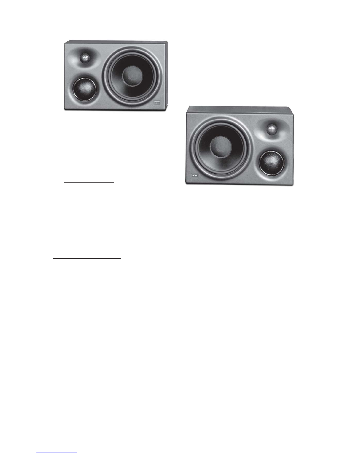
Figure 1 Front view
TT
TT
T
able of Contents:able of Contents:
able of Contents:able of Contents:
able of Contents:
Safety Instructions............................................2
Table of Contents..............................................3
1. Installation and Operation..........................4
1.1 Important Notes on Safety.........................4
1.2 Operating Conditions.................................4
1.3 Speaker Placement...................................4
1.4 MAINS Connection....................................4
1.5 MAINS Switch.............................................4
1.6 MAINS Fuse...............................................4
1.7 Level / Room Compensation / Ground Lift ..5
1.7.1 XLR Input.................................................5
1.7.2 BNC Input................................................5
1.7.3 Level ATT(ENUATOR)...........................6
1.7.4 INPUT SELECTOR Switch..................6
1.7.5 EQ (Room Compensation)...................6
1.7.6 GROUND LIFT.......................................7
1.8 CONTROLLER..........................................7
1.8.1 CONTROLLER SELECT Switch........7
1.9 Display Functions......................................7
1.10 Front Grille................................................7
1.11 Care of the Cabinet.................................7
2. Test Measurements......................................8
3. Warranty Information..................................10
4. Technical Specifications...........................11
Page 4

Page 4 Active Studio Monitor O 300 D
1. Installation and Operation1. Installation and Operation
1. Installation and Operation1. Installation and Operation
1. Installation and Operation
1.1 1.1
1.1 1.1
1.1
It is absolutely essential that you readIt is absolutely essential that you read
It is absolutely essential that you readIt is absolutely essential that you read
It is absolutely essential that you read
and observe the Safety Instructions onand observe the Safety Instructions on
and observe the Safety Instructions onand observe the Safety Instructions on
and observe the Safety Instructions on
page 2 before connecting or using thispage 2 before connecting or using this
page 2 before connecting or using thispage 2 before connecting or using this
page 2 before connecting or using this
device.device.
device.device.
device.
1.2 1.2
1.2 1.2
1.2
Operating conditionsOperating conditions
Operating conditionsOperating conditions
Operating conditions
The K+H model O 300 D active studio monitor
is intended for use over a range of ambient
temperatures from +10° C to +40° C (+50° F to
+104° F). During transport or storage,
temperatures from -25° C to +70° C (-13° F to
158° F) are permissible.
1.3 Speaker placement1.3 Speaker placement
1.3 Speaker placement1.3 Speaker placement
1.3 Speaker placement
The loudspeaker chassis used in the O 300 D
are magnetically shielded, so you are free to set
the speakers right next to a video monitor without
needing to worry about adversely affecting the
screen. Furthermore, the baffle of the O 300 D
is designed in such a way as to disperse the
sound very evenly not just on axis but over quite
a wide listening area. Any engineer who has sat
at a console for any length of time will appreciate
the considerable freedom of movement afforded
by the O 300 D. The cabinet is normally designed
to be used in the horizontal position, as the
vertical angle of dispersion has intentionally been
made narrower than the horizontal. The cabinets
are constructed in a left version and a right
version. For best stereo imaging and depth of
soundstage, position the cabinets with the
tweeters on the outside, at ear height, pointing
directly at the listening position. If you use the
O 300 D as a center speaker, set the cabinet
vertically, with the tweeter and midrange dome
at the top.
In certain applications where there are hard
reflective surfaces immediately to the left or right
of the speakers, it may make more sense to set
the cabinets vertically, in which case the
narrower dispersion pattern will help reduce
comb-filter effects.
When choosing a location for the speakers, be
aware that you can take advantage of the integral room-compensating equalizer, which will be
described in detail in section 1.7.5 .
The cabinet can be mounted directly to a wall or
ceiling with the aid of the LH 25 mounting
bracket. On the left and right sides of the cabinet
you will find threaded bushings of 8 mm diameter
to which this bracket attaches. As an alternative, you can use the LH 28 stand-mount adapter
to set the speaker on a standard 35-mm
(1-3/8”) tripod.
Please make certain that these two threaded
openings are always sealed, either with the
plastic plugs that come standard with the
cabinets or with the screws holding the mounting
adapter in place. Otherwise you may experience
some air noise and possibly some degradation
in low-frequency response.
1.4 MAINS 1.4 MAINS
1.4 MAINS 1.4 MAINS
1.4 MAINS
ConnectionConnection
ConnectionConnection
Connection
The amplifier electronics of the standard
European model are set up for an AC line voltage
of 230 volts, 50 or 60 Hz. Export versions with
other voltages are also available. If the power
plug of the mains cable should ever need to be
replaced, ensure that the connection to the
protective earth is maintained.
1.5 MAINS Switch (POWER)
When you switch on power to the unit, there is a
five-second delay before the amplified signal is
sent to the drivers. This delay avoids the loud
popping sounds that otherwise may be
generated by devices earlier in the signal chain
as power reaches them. You will find this
arrangement particularly useful if your studio
uses a master switch to power up all the
equipment at once. When power on the O 300 D
is turned off, on the other hand, or if there is a
general power failure, the signal flow to the
speaker is immediately cut off, preventing any
loud pops.
1.6 Mains FUSE1.6 Mains FUSE
1.6 Mains FUSE1.6 Mains FUSE
1.6 Mains FUSE
When replacing the fuse,
first disconnect the
mains cable
and ensure that the new fuse is of
the following type only:
for 230 volts AC 1.6 A Slo-Blo (5 x 20 mm)
for 117 volts AC 3.15 A Slo-Blo (5 x 20 mm)
for 100 volts AC 4 A Slo-Blo (5 x 20 mm)
12
10
13
Page 5

Active Studio Monitor O 300 D Page 5
1.7 LEVEL / ROOM COMPENSA1.7 LEVEL / ROOM COMPENSA
1.7 LEVEL / ROOM COMPENSA1.7 LEVEL / ROOM COMPENSA
1.7 LEVEL / ROOM COMPENSA
TION / GROUND LIFTTION / GROUND LIFT
TION / GROUND LIFTTION / GROUND LIFT
TION / GROUND LIFT
1.7.1 XLR INPUT1.7.1 XLR INPUT
1.7.1 XLR INPUT1.7.1 XLR INPUT
1.7.1 XLR INPUT
ANALOG / DIGITANALOG / DIGIT
ANALOG / DIGITANALOG / DIGIT
ANALOG / DIGIT
AL - AES/EBUAL - AES/EBU
AL - AES/EBUAL - AES/EBU
AL - AES/EBU
The sensitivity of the tranformer-balanced
floating input is +6 dBu (1.55 V). The threepin female XLR jack is wired in the standard
manner (pin 1 = ground, pin 2 = +, pin 3 = -).
If you are connecting unbalanced analog
sources, you will need to solder a bridge
between pins 1 and 3:
In digital mode, this same XLR input accepts
the digital signal according to the AES/EBU
specification (110 Ohm balanced).
1.7.2 INPUT:1.7.2 INPUT:
1.7.2 INPUT:1.7.2 INPUT:
1.7.2 INPUT:
DIGITDIGIT
DIGITDIGIT
DIGIT
AL INPUT / THROUGHAL INPUT / THROUGH
AL INPUT / THROUGHAL INPUT / THROUGH
AL INPUT / THROUGH
This digital input, configured as a 75-Ohm
BNC connector, is intended to receive signal
sources in S/P-DIF or AES 3id format. The
incoming digital signal line requires
oneone
oneone
one
75 -Ohm terminator at the very end, as the
O 300 D has no internal termination.
The XLR input and the BNC input are wired
in parallel across a transformer. The fact that
the termination is wired externally allows you
to make connections in a wide variety of
ways:
1.7.2.1 Source 1x AES/EBU, monitors1.7.2.1 Source 1x AES/EBU, monitors
1.7.2.1 Source 1x AES/EBU, monitors1.7.2.1 Source 1x AES/EBU, monitors
1.7.2.1 Source 1x AES/EBU, monitors
connected with each other via BNC cableconnected with each other via BNC cable
connected with each other via BNC cableconnected with each other via BNC cable
connected with each other via BNC cable
To obtain an output voltage of 1 Vpp at the
BNC-output connector (with 75 - Ohm
terminator), an input voltage of 5 Vpp at the
AES/EBU input is required. This complies with
the rules for AES/EBU level. If the input level
varies, the output level does so accordingly.
2
1
Figure 2 Rear View
unbalanced balanced
as seen from solder terminals of male XLR
Page 6

Page 6 Active Studio Monitor O 300 D
1.7.2.2 Source 2x AES/EBU1.7.2.2 Source 2x AES/EBU
1.7.2.2 Source 2x AES/EBU1.7.2.2 Source 2x AES/EBU
1.7.2.2 Source 2x AES/EBU
1.7.2.3 Source 1x S/P-DIF or 1x AES 3id,1.7.2.3 Source 1x S/P-DIF or 1x AES 3id,
1.7.2.3 Source 1x S/P-DIF or 1x AES 3id,1.7.2.3 Source 1x S/P-DIF or 1x AES 3id,
1.7.2.3 Source 1x S/P-DIF or 1x AES 3id,
connection using two T - connectorsconnection using two T - connectors
connection using two T - connectorsconnection using two T - connectors
connection using two T - connectors
1.7.2.4 Source 2x S/P-DIF or 2x AES 3id1.7.2.4 Source 2x S/P-DIF or 2x AES 3id
1.7.2.4 Source 2x S/P-DIF or 2x AES 3id1.7.2.4 Source 2x S/P-DIF or 2x AES 3id
1.7.2.4 Source 2x S/P-DIF or 2x AES 3id
1.7.3 Level A1.7.3 Level A
1.7.3 Level A1.7.3 Level A
1.7.3 Level A
TT(ENUTT(ENU
TT(ENUTT(ENU
TT(ENU
AA
AA
A
TOR)TOR)
TOR)TOR)
TOR)
This rotary level control allows for continuous
damping of the input signal in a range from 0
to -24 dB in both analog and digital modes.
1.7.4 INPUT SELECTOR Switch1.7.4 INPUT SELECTOR Switch
1.7.4 INPUT SELECTOR Switch1.7.4 INPUT SELECTOR Switch
1.7.4 INPUT SELECTOR Switch
Use a screwdriver to change the position of
this recessed switch in order to select analog or digital mode of operation. Since one
digital input carries both stereo channels, the
Input Selector has three additional positions
for establishing how the monitors are
assigned to the channels. This works as
follows:
Position A = Analog mode (XLR input)
Position R = Digital mode right channel
Position L = Digital mode left channel
Position M = Digital mode mono (summed
from both left and right channels)
Simultaneous operation from one analog and
one digital source is not possible. At any given
time you may connect only one type of source
to the pair.
1.7.5 EQ (Room compensation)1.7.5 EQ (Room compensation)
1.7.5 EQ (Room compensation)1.7.5 EQ (Room compensation)
1.7.5 EQ (Room compensation)
Three 4-way recessed rotary switches
(adjustable with a screwdriver) are available
for frequency compensation due to room
acoustics and speaker placement.
1.7.5.1 BASS Switch1.7.5.1 BASS Switch
1.7.5.1 BASS Switch1.7.5.1 BASS Switch
1.7.5.1 BASS Switch
For equalizing anomalies in the lower
frequencies due to proximity to room
boundaries:
Position 0 = free space
Position -3 = 1 boundary (wall)
Position -6 = 2 boundaries (corner)
Position -9 = 3 boundaries (corner + ceiling)
1.7.5.2 MID Switch1.7.5.2 MID Switch
1.7.5.2 MID Switch1.7.5.2 MID Switch
1.7.5.2 MID Switch
For equalizing anomalies in the midrange due
to reflections arising from placement on the
console’s meter bridge:
Position 0 = free space
Position -2 = mid reduction of -2 dB
Position -4 = mid reduction of -4 dB
Position -6 = mid reduction of -6 dB
1.7.5.3 HIGH Switch1.7.5.3 HIGH Switch
1.7.5.3 HIGH Switch1.7.5.3 HIGH Switch
1.7.5.3 HIGH Switch
Compensates for high-frequency anomalies
due to excessive reflection or absorption in
the room:
Position 1 = treble boost of +1 dB
Position 0 = linear
Position -1 = treble reduction of -1 dB
Position -2 = treble reduction of -2 dB
Note: Since it is not feasible to list all possible
combinations of speaker placement and room
acoustics, we strongly recommend checking
the switch settings acoustically or by
measurement.
4
3
6
5
7
Page 7

Active Studio Monitor O 300 D Page 7
The controls protected beneath theThe controls protected beneath the
The controls protected beneath theThe controls protected beneath the
The controls protected beneath the
plastic caps may not beplastic caps may not be
plastic caps may not beplastic caps may not be
plastic caps may not be
tampered with under anytampered with under any
tampered with under anytampered with under any
tampered with under any
circumstances!circumstances!
circumstances!circumstances!
circumstances!
1.7.6 GROUND LIFT1.7.6 GROUND LIFT
1.7.6 GROUND LIFT1.7.6 GROUND LIFT
1.7.6 GROUND LIFT
Since the input is transformer-balanced and
floating, you should rarely experience any
hum. In unusual cases, or if the source is
unbalanced, it may be necessary to lift the
connection between signal ground and
chassis ground, in which case you will find
this little switch convenient. The chassis
ground remains always connected to the
protective earth conductor.
WW
WW
W
arning!arning!
arning!arning!
arning!
The protective earth conductor mustThe protective earth conductor must
The protective earth conductor mustThe protective earth conductor must
The protective earth conductor must
never be interrupted even for testnever be interrupted even for test
never be interrupted even for testnever be interrupted even for test
never be interrupted even for test
purposes! This may be dangerous topurposes! This may be dangerous to
purposes! This may be dangerous topurposes! This may be dangerous to
purposes! This may be dangerous to
life!life!
life!life!
life!
1.8 CONTROLLER1.8 CONTROLLER
1.8 CONTROLLER1.8 CONTROLLER
1.8 CONTROLLER
The O 300 D Studio Monitor includes controller
electronics (limiter and analog filtering) that are
finely tuned to match its three drivers. In order to
be compatible with future developments (such
as FIR - filter technology), a connector for
external controllers was included. Using this
connection renders the internal D/A converters,
analog input stages, filters and limiters inactive,
with the sole exception of the bass peak limiter.
For optimal power amp utilization even under
varying voltage conditions and loads, the peak
limiter in the woofer channel was left in, but the
thermo limiter is deactivated.
1.8.1 CONTROLLER SELECT Switch1.8.1 CONTROLLER SELECT Switch
1.8.1 CONTROLLER SELECT Switch1.8.1 CONTROLLER SELECT Switch
1.8.1 CONTROLLER SELECT Switch
This switch is used to deactivate the internal
controller. By way of the jack labeled
POWER - AMP DIRECT INPUT
you can feed in signals intended for the three
internal power amplifiers. This 7-pin female
XLR jack is wired as follows:
Pin 1 = woofer input +
Pin 2 = woofer input Pin 3 = midrange input +
Pin 4 = midrange input Pin 5 = tweeter input +
Pin 6 = tweeter input Pin 7 = ground
1.9 Display functions1.9 Display functions
1.9 Display functions1.9 Display functions
1.9 Display functions
The illuminated K+H logo serves as a status
indicator for the loudspeaker cabinet.
Constant red: Normal operation, internal
power in order
Blinking red: Overload protection circuitry
engaged
If the light is blinking, this indicates that the
overload-protection circuitry has been triggered,
as may happen while cuing up a tape deck or
while running sine wave signals through the
speakers for measurement purposes. Output
power is reduced to a level that takes the
speakers out of danger. If this happens, you must
search for the cause and possibly reduce the
monitoring level.
1.10 Front grille1.10 Front grille
1.10 Front grille1.10 Front grille
1.10 Front grille
A front grille for the speaker baffle is not included
as standard equipment, but one is available as
an option. This fine mesh metal grille (article
GO 300) is easy to attach and offers added
protection to the exposed components. The
acoustical effect on the speakers is minimal.
1.11 Care of the cabinet1.11 Care of the cabinet
1.11 Care of the cabinet1.11 Care of the cabinet
1.11 Care of the cabinet
The cabinet housing of the K+H O 300 D active
studio monitor is available in either a flocked or
enamel finish (charcoal: RAL color 7021). With
the flocked housing, a certain amount of “hair
loss” within the first few weeks is normal, and
can be avoided simply by going over the cabinet
8
9
14
11
Figure 3 Effects of room compensation on
frequency
!
!
Page 8

Page 8 Active Studio Monitor O 300 D
Figure 4 Horizontal Dispersion Pattern
Figure 5 Vertical Dispersion Pattern
with a vacuum cleaner once it has been set in
place. The housing should be cleaned of dust
from time to time in like manner. If you plan on
taking your monitors from studio to studio, the
flocked finish is preferable since it wears well.
For non-mobile use, the enamel finish is
preferred, as it won’t be subject to any extreme
wear and tear. Take care when handling the
enamel - coated cabinet not to damage the finish.
To clean the cabinet, use a soft cloth with a mild
cleaning agent only. Under no circumstances
should you use alcohol - based or chemical
agents, nor any cleaners with abrasive action.
2. T2. T
2. T2. T
2. T
est Measurementsest Measurements
est Measurementsest Measurements
est Measurements
The outstanding acoustic impression made by the
O 300 D is confirmed by measurements using
today’s most critical test methods. The test plots
shown here and on the next several pages are
but a small sampling of these measurements.
Page 9

Active Studio Monitor O 300 D Page 9
Using the new material LRIM (
LL
LL
Low
RR
RR
Resonance
II
II
Integral
MM
MM
Molding) allowed us to seamlessly
integrate a waveguide into the baffle that is ideal
for optimal dispersion, with a mild horn-shape
around the mid-range dome and an elliptical horn
for the tweeter. Thus came to be the dispersion
pattern we mentioned earlier which is narrower
vertically and broader horizontally, as is clearly
evident in the test plots presented in Figures 4
and 5.
Figure 6 Free-field response
Figure 7 Distortion @ 95 dB at a
distance of 1 meter
Figure 8 Group delay
Page 10

Page 10 Active Studio Monitor O 300 D
Since the enclosure is sealed, the increase in
group delay at low frequencies (Figure 8) is quite
minimal, resulting in particularly tight, precise
bass response.
The spectral decay plot of the loudspeaker
reveals excellent decay and an absence of
Figure 9 Cumulative spectral decay (waterfall)
3. W3. W
3. W3. W
3. W
arranty Informationarranty Information
arranty Informationarranty Information
arranty Information
All K+H products undergo an extensive procedure of quality control testing before leaving
the factory. Before semiconductors are mounted
on the circuit board, they are subject to rigorous
tests. Every single unit is guaranteed to match
its technical specifications within strict predetermined tolerances.
Please store the original carton in a safe, dry
place. If you should ever need warranty service,
put the unit in its original packing material and
carton together with a detailed description of the
problem, and ship it (freight prepaid) to our
distributor.
K+H warrants, that the product is free from any
defects in both material and manufacturing and
that it meets the specifications. A warranty case
can only be acknowledged under condition that
the complaint is filed to our distributor or to us in
writing
within 8 dayswithin 8 days
within 8 dayswithin 8 days
within 8 days after delivery or detection
of the fault. Not covered under this warranty are
damages due to inexpert packing and shipment,
wear and tear, improper handling, installation,
operation and maintenance.
The limitation period for warranty claims is
described in the terms and conditions of K+H
GmbH. Its our choice to repair, to supply a new
product or to withdraw from the contract.
In the event warranty service is required,
presentation of a warranty card will not be
necessary. Proof of purchase date can be made
by filing copies of appropriate documents (invoice, delivery note).
unwanted overtones and standing waves.
Page 11

Active Studio Monitor O 300 D Page 11
4. T4. T
4. T4. T
4. T
echnical Specificationsechnical Specifications
echnical Specificationsechnical Specifications
echnical Specifications
O 300 DO 300 D
O 300 DO 300 D
O 300 D
Maximum SPLMaximum SPL
Maximum SPLMaximum SPL
Maximum SPL
in half-space, 3% THD at 1 m distance 112.8 dB/SPL
averaged between 100 Hz and 6 kHz
Free-field Frequency ResponseFree-field Frequency Response
Free-field Frequency ResponseFree-field Frequency Response
Free-field Frequency Response 40 Hz - 20 kHz ( ± 2 dB)
Self-noise Self-noise
Self-noise Self-noise
Self-noise
@10 cm@10 cm
@10 cm@10 cm
@10 cm 20 dB(A)
TT
TT
T
otal Harmonic Distortionotal Harmonic Distortion
otal Harmonic Distortionotal Harmonic Distortion
otal Harmonic Distortion
100 Hz and above @1m < 0.5% @95dB/SPL
ElectronicsElectronics
ElectronicsElectronics
Electronics
Power amplifiers
Bass amplifier 150 watts RMS (THD < 0.1%)
250 watts peak
Midrange amplifier 65 watts RMS (THD < 0.1%)
75 watts peak
Treble amplifier 65 watts RMS (THD < 0.1%)
110 watts peak
Controller type analog, active (also accepts external controller)
Crossover Crossover frequencies 650 Hz / 3.3 kHz
Crossover slopes 24 dB / octave
Room EQ Bass 0; -3; -6; -9 dB
Mid 0; -2; -4; -6 dB
High +1; 0; -1; -2 dB
Subsonic filter
Cut-off frequency 30 Hz
Slope 6 dB / octave
Protection circuitry Limit against overloading of LF, MF, and HF drivers
Analog input Impedance 14 kOhm (transformer-balanced and floating)
Sensitivity +6 dBu
Volume control continuously variable from 0 dB to -24 dB
Common mode rejection >70 dB @ 15 kHz
Digital inputs and outputs
XLR: AES/EBU impedance 110 Ohms, transformer balanced and
floating
BNC: S/P-DIF, AES 3id 75 Ohms, unbalanced
Terminator 75 Ohms, for BNC jack (external, not included)
Sensivity –12,5 dBFs
Volume control continuously variable from 0 dB to -24 dB
Switch analog / digital left / digital mono / digital right
Digital convertor Resolution, Type 24-bit DA, Delta - Sigma
Sampling rate 32 - 96 kHz
Page 12

Page 12 Active Studio Monitor O 300 D
Indicators Operational status K+H logo constantly illuminated
Limit/Clip K+H logo blinking
Mains Power fixed voltage, verify on device label
Power consumption
Idle 18 VA
Full power 240 VA
Physical characteristicsPhysical characteristics
Physical characteristicsPhysical characteristics
Physical characteristics
Connectors
Mains Three terminal Euro connector
Analog / digital inputs XLR connector, 3-pin
Digital inputs / outputs B N C
Direct ins to power amps XLR connector, 7-pin
Drivers, magnetically shielded
LF system 210 mm (8’’) Ø, 8 Ohms, polypropylene cone
Midrange system 76 mm (3’’) Ø, 8 Ohms, soft dome
HF system 25 mm (1’’) Ø, 6 Ohms, Titanium dome tweeter
Cabinet finish enamel or nylon-fiber flock
Cabinet color
Standard version charcoal-gray (RAL 7021)
Other colors optional
Loudspeaker covering optional fine-mesh metal grille
Mounting options 2x M 8 threaded bushings on sides
for use with LH 25 mounting bracket
2x rear angle brackets with predrilled ¼’’ holes
Mounting adapters LH 28 tripod fixture
for use only with LH 25 mounting bracket
LH 29 TV pin
for use only with LH 25 mounting bracket
Dimensions (W x H x D) 383 mm x 253 mm x 290 mm (310 mm with grille)
15’’ x 10’’ x 11½’’ (12¼’’ with grille)
Volume 28 litres / 0.99 cubic feet
Weight 13.5 kg / 30 lbs
Page 13

K+H Vertriebs- und Entwicklungsgesellschaft mbH
30900 Wedemark, Germany
Phone +49 (5130) 58 48 40
Fax +49 (5130) 58 48 11
www.klein-hummel.com
Printed 08/06 518283
 Loading...