

Page 1

DN1414
OPERATORS MANUAL
Version2
Klark Teknik Group,
Klark Teknik Building,
Walter Nash Road,
Kidderminster.
Worcestershire.
DY11 7HJ.
England.
Tel:+44 1562 741515
Fax:+44 1562 745371
Email: sales@ktgplc.com
Website: www.klarkteknik.com
Page 2

Page 3

Walter Nash Road, Kidderminster, Worcestershire. DY11 7HJ. England
Tel: (44) (0) 1562 741515. Fax: (44) (0) 1562 745371
Company Registration No: 2414018
abc d abc
SIGNAL PROCESSING BY DEFINITI ON BETTERBYDESIGN DESIGNEDFOR APUREPERFORMANCE
DECLARATION OF CONFORMITY
Klark Teknik Group (UK) Plc
We,
of, Klark Teknik Building, Walter Nash Road, Kidderminster, Worcestershire, DY11 7HJ
Declare that a sample of the following product:-
Product Type Number Product Description Nominal Voltage (s) Current Freq
DN1414 115V AC 130mA 50/60Hz
230V AC 260mA
to which this declaration refers, is in conformity with the following directives and/or standards:-
Directive(s) Test Standard(s)
Generic Standard Using EN55103 Limits and Methods EN50081/1
Class B Conducted Emissions Pavi EN55103
CLass B Radiated Emissions Pavi EN55103
Fast Transient Bursts at 2Kv EN61000-4-4
Static Discharge at 4Kv EN61000-4-2
Electrical Stress Test EN60204
Signed:............................
Name: David Hoare
Date: 4th February, 2000
Authority: Technical Director, Klark Teknik Group (UK) Plc
Attention!
Where applicable, the attention of the specifier, purchaser, installer or user is drawn to special limitations of use
which must be observed when these products are taken into service to maintain compliance with the above
directives. Details of these special measures and limitations to use are available on request and are available
in product manuals.
A Subsidiary of Telex communications, Inc.
Page 4

Page 5

Contents
Thank you for using a Klark Teknik product
After you have unpacked
Introduction
Installation and Connection
Basic operation
Front Panel
Rear Pane
Rear panel blanking plate and iser multipole connectors
Block Diagram
Applications
Appendices
Specifications
Schematics
Page 1
Page 2
Page 3
Page 4
Page 5
Page 6
Page 7
Page 8
Page 9
Page 10
Page 11
Page 12
Page 13
Page 6

Page 7

.
Thank You For Using This Klark Teknik Product
To obtain maximum performance from this precision electronic product, please study these instructions
carefully. Installation and operating the mic splitter is not complicated, but the flexibility provided by its
operating features merits familiarisation with its controls and connections. This unit has been prepared to
comply with the power supply requirements that exist in your location.
Precautions
Do not install this unit in a location subjected to excessive heat, dust or mechanical vibration.
Voltage Selection and Power Connection
Connection is made by means of an IEC standard power socket. The rear panel text indicates the voltage
range required for satisfactory operation of the unit.
Before connecting this unit to the mains supply, ensure the fuse fitted is the correct type and rating is as
indicated on the rear panel, adjacent to the fuse holder.
Safety Warning
This unit is fitted with 3-pin power socket: For safety reasons the earth lead should not be disconnected.
Signal ground is referenced internally to chassis via a resistor capacitor network which provides earth
loop immunity.
To prevent shock or fire hazard, do not expose the unit to rain or moisture. To avoid electrical shock do
not remove covers. Refer servicing to qualified personnel only.
Attention!
Cables:
This product should only be used with high quality, screened twisted pair audio cables, terminated either
with metal bodied 3-pin XLR connectors(with the cable screen connected to pin 1) or ¼” jacks. Any other
cable type or configuration for the audio signals may result in degraded performance due to
electromagnetic interference.
Electric Fields:
Should this product be used in an electromagnetic field that is amplitude modulated by an audio
frequency signal (20Hz to 20kHz), the signal to noise ratio may be degraded. Degradation of up to 60dB
at a frequency corresponding to the modulation signal may be experienced under extreme conditions
(3V/m, 90% modulation).
1
Page 8
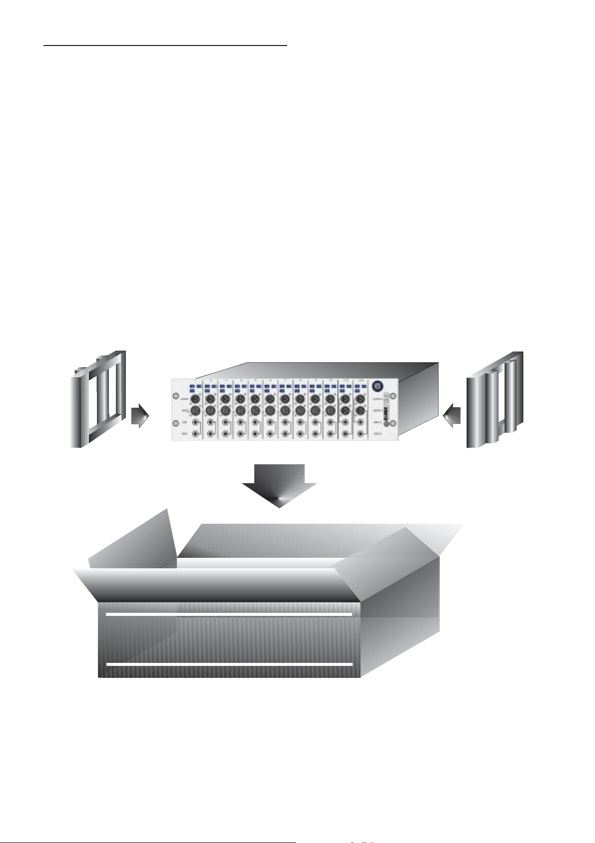
After You Have Unpacked The Unit
Save all the packing materials - they will prove valuable should it become necessary to transport or ship
this product.
Please inspect this unit carefully for any signs of damage incurred during transportation. It has undergone
stringent quality control inspection and tests prior to packing and left the factory in perfect condition.
If, however, the unit shows any signs of damage, notify the transportation company without delay. Only
you, the consignee, may institute a claim against the carrier for damage during transportation.
If necessary, contact your supplier or as a last resort, your Klark Teknik importing agent, who will fully
co-operate under such circumstances.
Side Up
This
L
2
abc
Page 9

Introduction
The DN1414 Multiple DI Module offers a cost and space-effective method of providing 14 discrete channels
of transformer-isolated direct injection. Housed in a rugged 3U rack enclosure, the DN1414 embodies the
legendary sound and reliability of Klark Teknik.
Key Features
i Ten mono channels with XLR and jack inputs, link output jack and transformer
-balanced XLR outputs.
ii. Two dual channels with jack inputs, link output jacks and transformer-balanced
XLR outputs
iii. -30dB pad, -15 dB attenuation onall channels.
iv. Internal power supply with factory option of backupPSU.
v. Five year international factory warranty.
The Klark Teknik DN1414 is an extremely high performance, 14-channel DI module housed in a 3U, rack
mounting case with an integral switch mode power supply that automatically adapts to mains voltages in the
range 100 to 240 Volts (50 to 60Hz). A dual PSU is available as a factory fitted option. Applications include
providing DI box feeds to service monitor and FOH consoles as well as to facilitate the multitrack recording
of live events.
Each input feeds a superbly specified input stage, which can flexibly handle both line- and instrument-level
signals. The TRS jack and XLR inputs on channels 1-10 are parallel connected, and the circuit design allows
the DN1414 to handle either balanced or unbalanced signals without loss. A 20k ohm input impedance is
presented when the XLR input connector is used, this impedance is switched out when the jack input is used,
to avoid high-frequency loading effects when the DN1414 is used with unbuffered guitar pick-ups. All
connectors are mounted on the front panel for easy access. Two pad/attenuator switches (-30dB and -15dB)
may be used individually or in combination to provide unity, -15 dB, -30 dB or 45 dB gain. Each DI channel
output is also fitted with a groundlift switch.
3
Page 10

Installation And Connection
The Klark Teknik DN1414 is designed for standard 19" rack mounting and occupies 3U of rack space. Avoid
mounting the unit directly above or below power amplifiers or power supplies that radiate excessive
magnetic fields or heat. Ensure that the ventilation apertures on either side of the unit are not blocked or
obstructed.
This unit must be earthed. If ground loop problems are encountered, the ground lift switches on the channel
outputs may be used. It is also permissible to disconnect the cable screen at one end or other of the output
cables, though the signal input cable screen must be connected at both ends to ensure the phantom powering
operates correctly.
The mains fuse should beT0.5L250V.
The transformer-balanced outputs have a maximum signal capability of +18dB. For unbalanced use, pin 3 of
any output XLR may be grounded at the destination end of the cable. These outputs have a source impedance
of 70 and are designed to feed a minimumload of 600 .WW
4
Page 11

Basic Operation
Ensure that the soundsystem level is turned down at this stage
to prevent switch-on thumps or acoustic feedback. The
transformer balanced outputs offer exceptional audio quality
combined with excellent line driving capability. In addition
they offer absolute electrical isolation, which is essential in
situations such as running feeds to mobile studios or outside
broadcast facilities.
Illuminated Logo The DN1414 has no mains power switch.
When power is connected, the logo at the front right of the
panel will illuminate.
5
Page 12

Front Panel
Channels 1 to 10
-15dB Switches in a 15dB
attenuator. (Note that both
switches may be used together
when -45dB attenuation is
required.)
Lift Isolates the output signal
ground.
-30dB Switches in a -30dB pad in
front of the input bufferstage.
Input Balanced TRS jack socket,
parallel-connected with a 3-pin
female XLR.
Channels 11/12 and 13/14
Lift Isolates the output signal ground affects
both channels.
Output Transformer balanced
XLR output.
Link UnbalancedTS jack socket.
-15dB Switches in a 15dB attenuator. (Note that
both switches may be used together when -45dB
attenuation is required.) affects bothchannels.
30dB Switches in a -30dB pad in front of the
input bufferstage affects both channels.
Outputs Transformer balanced XLR output.
Inputs Balanced TRSjack sockets.
6
Page 13

Rear Panel
Blanking plate
Dimensions of the plate: 158mm x 88mm
Internal dimensions:140mm x 70mm
Mains Inlet
Standard non-switched IEC mains connector. A suitable
cable is provided.
7
Page 14

Rear Panel Blanking Plate and User Multipole Connections
The rear panel has a removable blanking plate which is designed for users to fit their choice of multipole
connectors. The circuit board for each for the twelve channels has a row of spring-leaf terminals along its rear
edge to allow users to terminate cablesfrom the mutipole connectors.
The top cover should be removed from the unit to gain access to the blanking plate and the circuit board
terminals. Please ensure that all screws are retained and used to re-attach the cover and blanking plate.
warranty claims resulting from damage to the unit will be void if all of the screws are not used to re-secure
both the cover and the blanking plate.
The outputs are brought out to the circuit board terminals; to make a connection insert a small flat-bladed
screwdriver into the upper rectangular slot and using a levering motion, move the screwdriver away from the
circuit board - this actionwill open the contacts in thelower opening in the connector so that thebare ends of a
wire can be inserted. Moving the screwdriver in the other direction will close the contacts, which will then
hold the wire securely.
these multipole connectors. It is recommended that screened twisted pair cable is used to make the
connections between the individual circuit boards andthe multipole connectors.
The connectors are as shown below forboth the mono anddual channel circuitboards:
Any warranty claims will be voidif the damage has been caused byexcessive force to
Any
Insert flat bladed-
screw driver here
to open multipole
connector
Ground (XLR pin 1)
Hot (XLR pin 2)
Cold
(XLR pin 3)
OUT
Insert flat bladed-
screw driver here
to open multipole
connector
Ground (XLR pin 1)
Hot (XLR pin 2)
Cold (XLR pin 3)
Ground (XLR pin 1)
Hot (XLR pin 2)
Cold (XLR pin 3)
OUT 11 (13)
OUT 12 (14)
Mono circuit board
Dual channel circuit board
Page 15

Block Diagram
DI Channel Configuration
The DI module input stage uses the same buffered preamplifier that is employed on many Klark Teknik
products and features exception low noise and distortion combined with a generous level of headroom, as
well as being able to handle both balanced and unbalanced input connections without signal loss. The
parallel-connected XLR and TRS jack inputs on channels 1-10 are designed to be used one at a time, the XLR
input has a 20k ohms input impedance, this is switched out when a jack plug is inserted so that guitars,
especially passive ones, can be used without loss of high frequency signal content. The nominal input
impedance when using the jack input is 1 M ohms.A -30dB pad can be switched in front of the buffer stage to
avoid clipping. A further separately buffered 15 dB attenuator is also included.The separate buffering means
that there will be no interaction between the pad and the attenuator when they are both switched in. With
neither selected, the signal path is unity gain. The gain range is adequate to accommodate most keyboards,
sound modules, instrument preamplifier outputs and activeand passive guitars andbasses.
9
Page 16

Applications
In a live concert situation, the DN1414is be used toprovide an isolatedtransformer-balanced feed suitable for
long cable runs fromthe stage to mixing desks. The main uses forthe DN1414 are for providing interfaces for
unbalanced outputs from electronic keyboards, sound modules or instrument pre-amps, or for instruments
such as bass and electro-acoustic guitars whichwould not normally beused with amicrophone.
Example 1 shows the usage with a bass guitar. The unbalanced output from the bass is connected to the jack
input of the DN1414, and the link output is used to provide a through connection to the bassist's on-stage
amplifier. The transformer output is then usedto provide a balanced feed to the monitorand/or FOH desks.
Example 2 shows the usage as an interface for a number of on-stage keyboards and sound modules. These
units do not normally have balanced outputs suitable for driving long cable runs, and so the use of DI units is
essential in this application. The compact rack-mounting format of the DN1414 makes it ideal for inclusion
in a keyboard rack. The transformer outputs are used to provide individual balanced feeds to the monitor
and/or FOH desks.
10
Page 17

Appendices
Architect's And Engineer's Specification
The Multiple DI Module shall provide 14 discrete audio channels in a standard 3U 19" rack mount chassis,
each channel providing galvanic isolation and impedancematching for a varietyof input signals.
Each channel shall also provide separate -30 dB pad and 15 dB attenuation switches, and an earth lift
function.
Each Multiple DI Module shall meet orexceed the following performancespecifications:
Distortion < 0.01% (1 kHz +4 dB)
Frequency response +/-1.0 dB (20 Hz to 20 kHz)
The DI Module shall have ten single audio channels and two dual audio channels. All channels shall have a
¼" TRS jack input which is capable of accepting balanced or unbalanced inputs. The ten single audio
channels shall have a female 3-pin XLR connector in parallel with the jack socket. In use the XLR input shall
present a 20k ohm input impedance andthe ¼" jack socketa nominal 1Mohm input impedance.
The ten single channels shall also havean unbalanced link outputon a ¼"TS jack socket.
All outputs shall be transformer isolated andshall use 3-pin maleXLR connectors.
The unit shall be capable of operatingfrom a 100 to240V, 50to 60 HzAC power source.
The DI Module shall be the KlarkTeknik model DN1414 andno alternative optionis available.
11
Page 18

Specifications
Inputs
Electronically balanced
Input impedance 1M nominal (Unbalanced)
Max level + 21dBu with no input attenuation
Attenuation - 15dB
Pad - 30dB
Connectors Parallel-connected ¼ " TRS jack sockets and
Outputs
Transformer isolated
Source impedance 50
Min Load 600 (-3dB level loss into 20 )
Max level > + 18dBu @ 1kHz with load > 1k
Connectors 3-pin female XLRs.
Link Output (Channels 1-10)
Connectors ¼" TS Mono Jack Socket
W
20k (Balanced)
W
3-pin female XLRs.
W
WW
W
Performance
Noise -100 dBu between 20Hz and 20 kHz unweighted
Frequency response +/- 1dB, 2Hz to 20kHz
Distortion <0.01% @ 1kHz, +4dBu output
Power Requirements
100 to 240 V a.c @ 50/60 Hz @ < 75 VA
3 pin IEC connector.
Dimensions
Width 483 mm (19 inches)
Height 132 mm (5.2 inches)
Depth 300 mm (12 inches)
Weights
Nett 8 kg
Shipping 9 kg
12
Page 19

Schematic Drawings
DN1414
Mutilple DI Module Power Schematic
Mutilple DI Module Stereo (Mono Option) Schematic 1
Mutilple DI Module Stereo (Mono Option) Schematic 2
13
Page 20

Page 21

Page 22

Page 23

Page 24

Page 25

Page 26

 Loading...