

Page 1
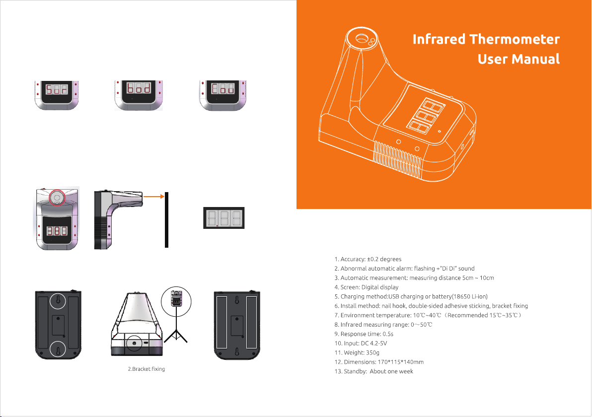
(3) S elect M easur ing Mod e
Lon g press m ode swi tch but ton for 3 s econd s to swit ch the te mpera ture mo de.
The d efaul t mode is b ody mod e.(Sur: s urfac e mode, b od: obj ect mod e , Cou:
cou nting m ode ). Th e “bod” m ode is pr ogram med by de fault .
Sur : surfa ce mode
bod : objec t mode
Cou : count ing mod e
Measurement
Mak e sure th e measu ring di stanc e is betw een 5-1 0 cm (1.9 7-3.9 4 in) whe n
mea surin g.
5~10cm
Sta tus & Tes ting Re sult
Installation Methods
1.Nail hook
3.Double-sided adhesive sticking
Specification
Page 2
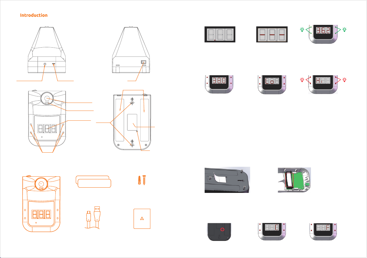
Status Description
Tripod mounting hole
Co nt en t
Alarm light
USB interface
Infrared thermometer
Infrared ranging sensor
Temperature display
Hanging hole
Double Sided Tape
Switch
Double-sided adhesive area
Plastic Plugs & Screws
Nameplate
Mode switch hole
1. St andby :
The r ed dot in t he
bot tom of th e displ ay
lig hts up in t urn.
4. Ab norma l
tem perat ure:
2. In suffi cient p ower:
The h orizo ntal ba r
lig hts up in t he midd le
of th e displ ay.
5. ‘L o’: Ult ra-lo w
tem perat ure ala rm.
3. No rmal te mpera ture:
Fla shing g reen li ghts
and a larm ‘ Di ’.
6. ‘H I’: Ult ra-hi gh
tem perat ure ala rm.
Fla shing r ed ligh ts
and a larm ‘D i Di’.
Operation Before Measurements
(1) P ower on
For f irst ti me use, o pen the c ase wit h screw d river , pull ou t the bat tery st rip,
put t he batt ery ins ide the b atter y compa rtmen t. Pres s [ power s witch ]
but ton to tu rn on the t hermo meter , then in itial ize the s ystem .
LCD w ill sho w the def ault va lue: 00 .0 °C.
-
+
(2) M easur ement u nit sel ectio n
Pre ss [swi tch but ton] on ce by usi ng a 3mm di amete r screw d river t o selec t the
mea surem ent uni t °C or °F (C : Celsi us F: Fah renhe it)
Main Unit
USB Cable User Manual
 Loading...