

KitchenAid OUTDOOR GRILL, 720-0826LP, 720-0826NG User Manual
FREESTANDING OUTDOOR GRILL
InstallationInstructionsandUse&CareGuide
For questions about features, operation/performance, parts, accessories or service, call: 1-877-373-2301
or visit our website at www.Kitchenaidgrills.com
ASADOR AUTÓNOMO PARA EXTERIORES
Instrucciones deinstalación yManualdeuso ycuidado
Para consultas respecto a características, funcionamiento, rendimiento, piezas, accesorios o servicio técnico, llame al:1-877-373-2301
o visite nuestro sitio de internet en www.Kitchenaidgrills.com
GRIL D'EXTÉRIEUR AUTOPORTANT
Instructionsd’installation etGuided’utilisation etd’entretien
Pour des questions à propos des caractéristiques, du fonctionnement/rendement, des pièces, des accessoires ou du service,
composer le : 1-877-373-2301 ou visiter notre site web www.Kitchenaidgrills.com
Table of Contents/Índice/Table des matières..................................................... ... ... ...................... 2
720-0826 (LP) 730-0826(NG)
19000409A1

TABLE OF CONTENTS
OUTDOOR GRILL SAFETY……………………………… 3
INSTALLATION REQUIREMENTS……………………… 5
Tools and Parts…..………………………………………… 5
Location requirements……………………………….……. 5
Product Dimensions……………………………………….. 6
Electrical Requirements…………………………………... 6
Gas Supply Requirements………………………………… 7
Gas Connection Requirements…………………………… 8
PACKAGE CONTENTS LIST …………………………….9
REPLACEMENT PARTS…………………………………. 10
INSTALLATION INSTRUCTIONS……………………….. 13
Freestanding Outdoor Grill Installation…………………... 13
Make Gas Connection…………………………...…………17
GAS CONVERSION…………………………………......... 18
Tools and Parts for Gas Conversion……………….......... 18
Conversion from LP Gas to Natural Gas……………....... 19
ÍNDICE
SEGURIDAD DEL ASADOR PARA EXTERIORE…….. 38
REQUISITOS DE INSTALACIÓN ………………………. 39
Herramientas y piezas ………...………………………….. 39
Requisitos de ubicación …………………………………... 39
Medidas del producto ………………………………….......41
Requisitos eléctricos………………………………………. 41
Requisitos del suministro de gas …………………...........42
Requisitos para la conexión de gas ………………….......43
LISTA DE CONTENIDO DEL PAQUETE…………..……44
PIEZAS DE REPUESTO …………………………………. 45
INSTRUCCIONES DE INSTALACIÓN ………………… 48
Instalación del asador autónomo para exteriores …….. 49
Conexión del suministro de gas …………………………. 52
CONVERSIONES DE GAS ……………………………… 53
Herramientas y piezas para la conversión de gas …...... 54
Conversión de gas LP a gas natural ……………………..54
Revise y regule los quemadores ……………………........58
Check and Adjust the burners……………………………..23
OUTDOOR GRILL USE……………………………………24
Using Your Outdoor Grill…………………………....…….. 24
Prepare Your Grill for Lighting……………………………. 25
TIPS FOR OUTDOOR GRILLING……………..………… 29
Cooking Methods……………………………………………29
Grilling Chart………………………………………………... 30
OUT DOOR GRILL CARE…………………………...…… 32
Replacing the Igniter Battery……………………………… 32
Changing the Grill Light Bulb………………………………32
General Cleaning……………………………………………33
TROUBLE SHOOTING................................................... 35
ASSISTANCE……………………………………………… 35
WARRANTY………………………………………………... 36
USO DEL ASADOR PARA EXTERIORES……….…….. 59
Cómo usar el asador para exteriores…………….………. 59
Prepare el asador para encenderlo………………….…… 60
CONSEJOS PARA ASAR AL AIRE LIBRE……………..64
Métodos de cocción …………………………………..…… 64
Cuadro para asar ……………………………………...……65
CUIDADO DEL ASADOR PARA EXTERIORES….....… 67
Cómo reemplazar la batería del encendedor …………… 67
Limpieza general ………………………..…………………. 70
SOLUCIÓN DE PROBLEMAS……………………….……70
ASISTENCIA…………………………...……………………70
GARANTÍA ……………………….………………………… 71
TABLE DES MATIÈRES
SÉCURITÉ DU GRIL D'EXTÉRIEUR ………..…………..73
EXIGENCES D’INSTALLATION ……………..…………. 75
Outils et pièces ……………...………………..…………….75
Exigences d'emplacement …………………..…………….75
Dimensions du produit ………………………….……........76
Spécifications de l'alimentation en gaz …………………..77
Exigences concernant le raccordement au gaz……….... 78
LISTE DU CONTENU DE L'EMBALLAGE……………...79
PIÈCES DE RECHANGE ………………………………… 80
CONSIGNES D’INSTALLATION…………………….…...83
Installation du gril d’extérieur autoportant ………………. 83
Raccordement au gaz …………………………...………...87
CONVERSIONS POUR CHANGEMENT DE GAZ ……. 88
Outils et pièces pour conversion de gaz …………….......88
Conversion de propane à gaz naturel ……………………89
Contrôle et réglage des brûleurs ………………….….......93
2
UTILISATION DU GRIL D’EXTIEUR ………………….... 94
Utilisation du gril d’extérieur ………………………….…... 94
CONSEILS POUR L'UTILISATION DU GRIL
D'EXTÉRIEUR ...............................................................99
Méthodes de cuisson ………………………………………99
Tableau de cuisson au gril ……………………………….. 100
ENTRETIEN DU GRIL D’EXTÉRIEUR …………………. 103
Remplacement de la pile de l’allumeur …………………. 103
Nettoyage général ……………………………………........ 104
DÉPANNAGE..................................................................106
ASISTANCE…………………………………………………106
GARANTIE…………………………………………………..107
OUTDOOR GRILL SAFETY
3.Open lid.
3.Open lid.
DANGER
If you smell gas:
1.Shut off gas to the appliance.
2.Extinguish any open flame.
4.If odor continues, keep away from the
appliance and immediately call your gas
supplier or your fire department
State of California Proposition 65 Warnings:
WARNING: This product contains one or more chemicals known to the State of California to cause cancer.
WARNING: This product contains one or more chemicals known to the State of California to cause birth defects or other
reproductive harm.
In the State of Massachusetts, the following installation instructions apply:
Installations and repairs must be performed by a qualified or licensed contractor, plumber, or gasfitter qualified or licensed by
the State of Massachusetts.
If using a ball valve, it shall be a T-handle type.
A flexible gas connector, when used, must not exceed 3 feet.
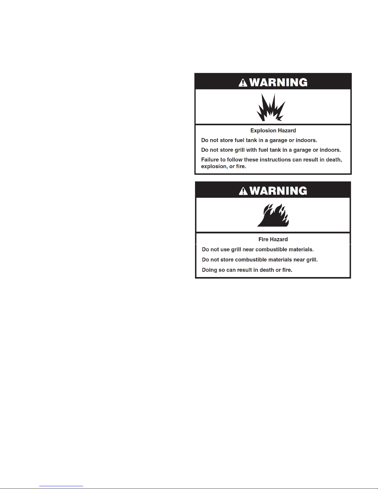
1. Do not store or use gasoline or other
flammable liquids or vapors in the vicinity
of this or any other appliance.
2. An LP cylinder not connected for use
shall not be stored in the vicinity of this or
any other appliance.
WARNING
IMPORTANT: This grill is manufactured for outdoor use only. For grills that are to be used at elevations above 2,000ft (609.6 m)
orifice conversion is required. See “ Gas Supply Requirements” section. It is the responsibility of the installer to comply with the
minimum installation clearances specified on the model/serial rating plate. The model/serial rating plate for freestanding models
can be found on the inside cabinet door.
3
IMPORTANT SAFETY INSTRUCTIONS
WARNING: To reduce the risk of fire, electrical shock,
Injury to persons, or damage when using the outdoor cooking
gas appliance, follow basic precautions, including the following:
Do not install portable or built-in outdoor cooking gas
appliances in or on a recreational vehicle, portable trailer,
boat or in any other moving installation.
Always maintain minimum clearances from
combustible construction, see “ Location
Requirements” section.
The outdoor cooking gas appliance shall not be located
under overhead unprotected combustible construction.
This outdoor cooking gas appliance shall be used only
outdoors and shall not be used in a building, garage, or
any other enclosed area.
Keep any electrical supply cord and fuel supply hose
away from any heated surfaces.
Keep outdoor cooking gas appliance area clear and
free from combustible material, gasoline and other
flammable vapors and liquids.
Do not obstruct the flow of combustion and ventilation
air. Keep the ventilation openings of the cylinder
enclosure free and clear from debris.
Open the cabinet door and Inspect the gas cylinder supply
hose before each use of the outdoor cooking gas appliance.
If the hose shows excessive abrasion or wear, or is cut, it
MUST be replaced before using the outdoor cooking gas
appliance. Contact your dealer and use only replacement
hoses specified for use with the outdoor
cooking gas appliance.
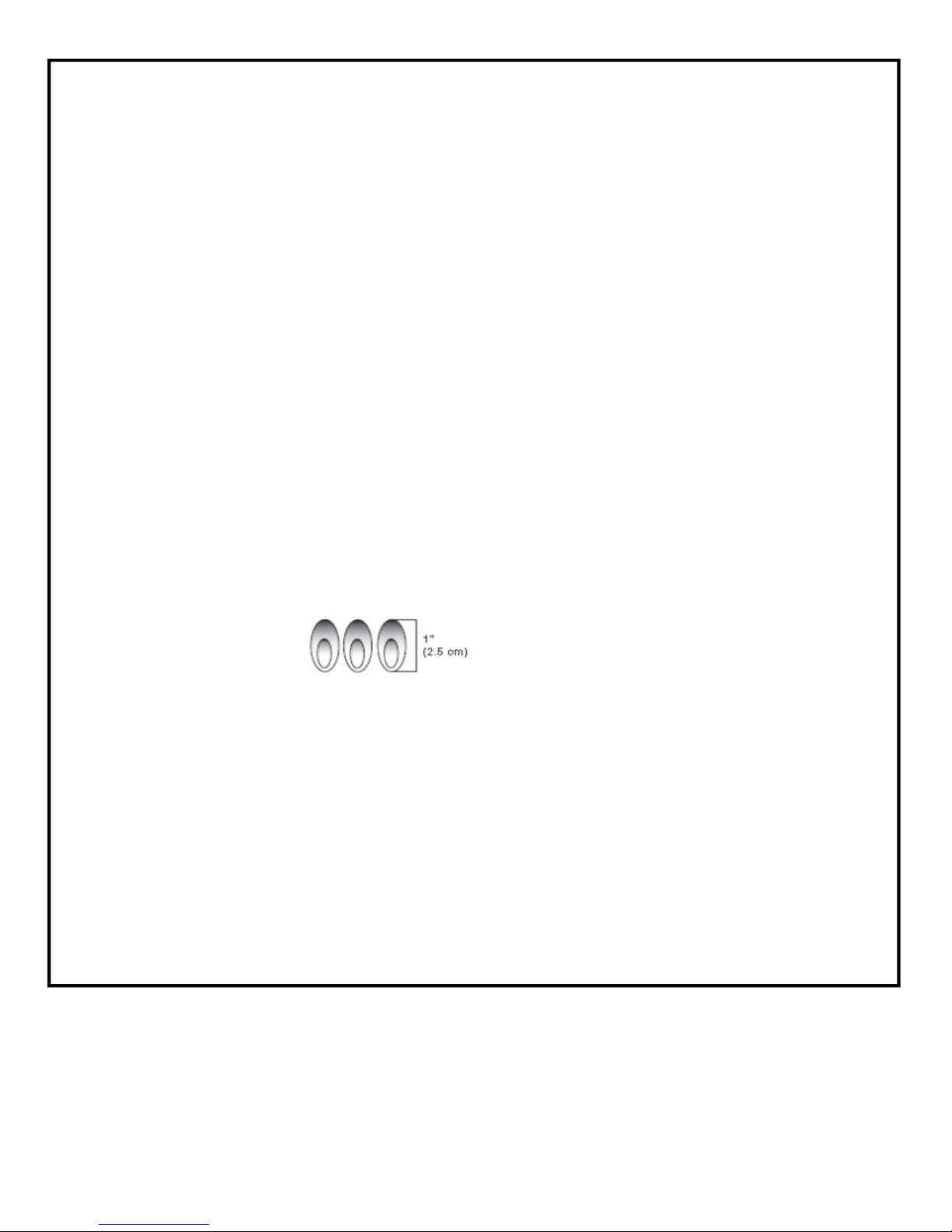
Visually check the burner flames.
They should be blue. Slight
yellow tipping is normal for
LP gas. The flames should
Be approximately 1" (2.5 cm) high.
Check and clean burner/venturi tube for insects and
insect nest. A clogged tube can lead to fire under the
outdoor cooking gas appliance.
The LP gas supply cylinder to be used must be:
- constructed and marked in accordance with the
Specification for LP Gas cylinders of the U.S. Department
of Transportation (DOT) or the National Standard of
Canada, CAN/CSA-b339, Cylinders, Spheres, and Tubes
for Transportation of Dangerous Goods; and Commission.
- provided with a listed overfilling prevention device.
- provided with a cylinder connection device compatible with
the connection for outdoor cooking gas appliances.
Always check connections for leaks each time you connect
and disconnect the LP gas supply cylinder. See “Installation
Instructions” section.
When the outdoor cooking gas appliance is not in use, the
gas must be turned off at the supply cylinder.
Storage of an outdoor cooking gas appliance indoors is
permissible only if the cylinder is disconnected and removed
from the outdoor cooking gas appliance Cylinders must be
stored outdoors and out of the reach of children and must
not be stored in a building, garage, or any other enclosed
area.
The pressure regulator and hose assembly supplied with the
outdoor cooking gas appliance must be used. A replacement
pressure regulator and hose assembly specific to your model
is available from your outdoor cooking gas appliance dealer.
Gas cylinder must include a collar to protect the cylinder
valve.
For appliances designed to use a CGA791 Connection:
Place a dust cap on cylinder valve outlet whenever the
cylinder is not in use. Only install the type of dust cap on the
cylinder valve outlet that is provided with the cylinder valve.
Other types of caps or plugs may result in leakage of
propane.
If the following information is not followed exactly, a fire
causing death or serious injury may occur.
Do not store a spare LP gas cylinder under or near this
outdoor cooking gas appliance.
Never fill the cylinder beyond 80 percent full.
SAVE THESE INSTRUCTIONS
4
Installation Requirements
Tools and Parts
Gather these required tools and parts before starting installation.
Read and follow the instructions provided with any tools listed
here.
Tools needed
Phillip screwdriver
Wrench or pliers
Pipe wrench
Parts Supplied
Gas pressure
regulator/hose assembly
set for 11” WCP LP gas
Side shelf, left
Side burner assembly
“AA” Battery (1)
Scissors or cutting pliers (to
remove tie-downs)
Noncorrosive leak-detection
solution
Warming rack
Cooking grids with hole
Main burner grease tray
Sear burner grease tray
Flame tamers
Natural gas orifice for sear
burner, side burner and rear
burner
Location Requirements
Parts Needed
20 lb LP gas fuel tank-approximately 18” (45.7cm) height.
Parts Needed for Conversion to Natural Gas
Natural gas conversion kit Part Number 710-0003. See
“Assistance” section to order. The conversion kit includes:
• Natural gas regulator 4" W.C. (marked “Natural Gas
Regulator”)
• 10 ft (3.0 m) Natural gas hose with quick connector
• 5.9" (150 mm) Natural gas regulator hose
• 6 mm nut driver
• 6 mm wrench
• Hex key
Gas line shutoff valve
1/2" male pipe thread nipple for connection to pressure regulator.
LP gas-resistant pipe-joint compound
CSA design-certified outdoor flexible stainless steel appliance
connector (4-5 ft [1.2-1.5 m]) or rigid gas supply line as needed.
Select a location that provides minimum exposure to wind
and traffic paths. The location should be away from strong
draft areas.
Do not obstruct flow of combustion and ventilation air.
Clearance to combustible construction for grill:
A minimum of 24” (61 cm) must be maintained between
the front of the grill hood, sides and back of the grill
and any combustible construction.
A 24” (61 cm) minimum clearance must also be
maintained below the cooking surface, and the grill
shall not be used under overhead combustible
construction.
5
Product Dimension
M
C
)
5
.
8
"
7
(
0
1
1
/
3
0
7
C
7
1
"
(
6
1
4
)
M
"
5
/
3
2
1
C
5
"
(
5
/
6
3
5
2
M
)
Electrical Requirements
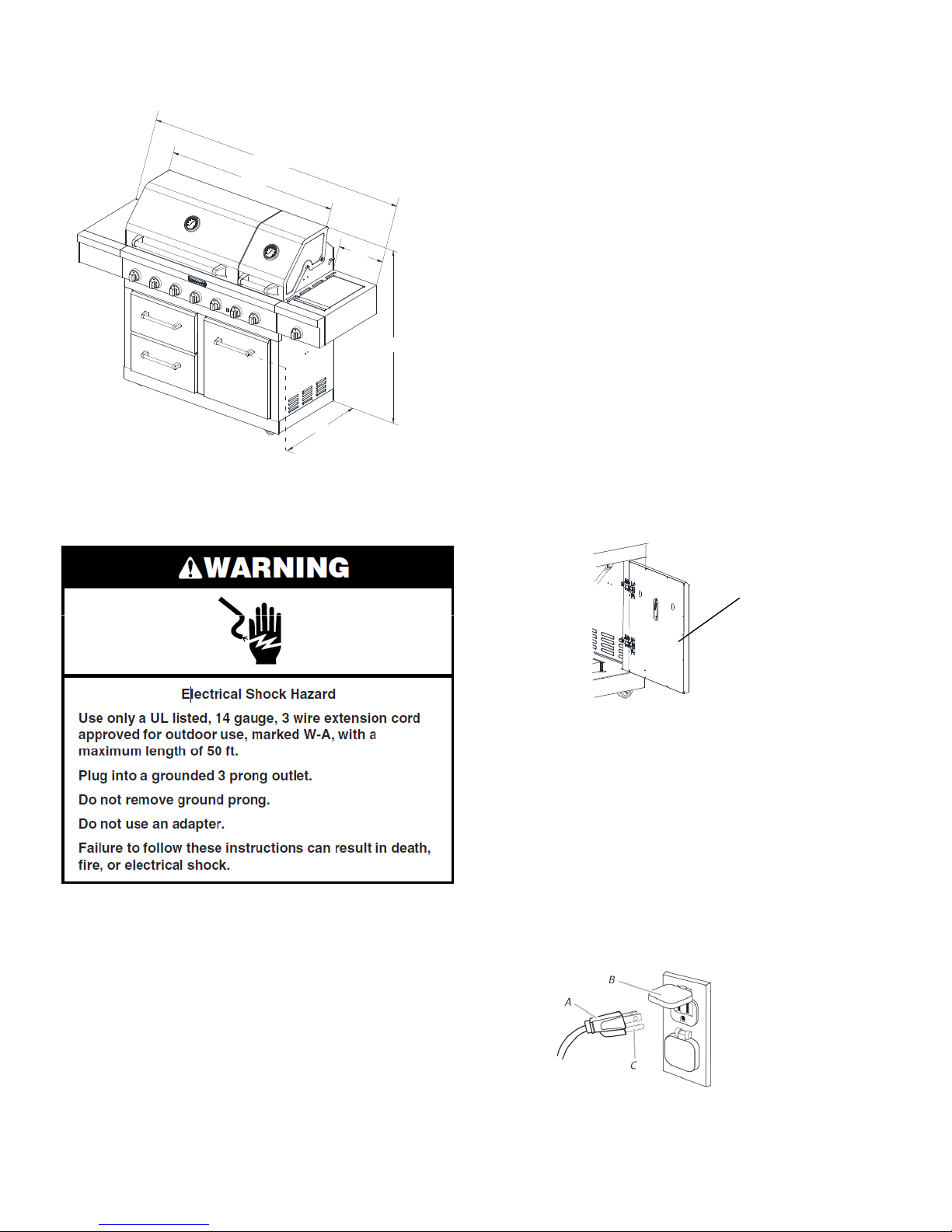
Unplug from the outlet when not in use and before cleaning.
Allow to cool before attaching or taking off parts.
Do not operate any outdoor cooking gas appliance with a
damaged cord, damaged plug, or after the appliance
malfunctions or has been damaged in any manner. Contact the
manufacturer for repair.
Do not let the cord hang over the edge of a table or touch hot
surfaces.
)
M
C
2
(
3
Do not use an outdoor cooking appliance for purposes other
than intended.
When connecting, first connect plug to the outdoor cooking gas
appliance then plug appliance into the outlet.
M
C
)
4
2
(
1
"
5
/
4
8
4
Use only a Ground Fault Interrupter (GFI) protected circuit with
this outdoor cooking gas appliance.
Do not remove the ground prong or use with an adapter of 2
prongs.
Use extension cords with a 3 prong grounding plug rated for
the power of the equipment and approved for outdoor use with
a W-A marking.
The model/serial number rating plate is located on the inside of the
left cabinet door. See the following illustration.
A. Model/Serial number plate
Electrical Requirements
If codes permit and a separate ground wire is used, it is
recommended that a qualified electrician determine that the
ground path is adequate.
Check with a qualified electrician if you are not sure whether the
grill is properly grounded.
A 120-volt, 60-Hz, AC-only, 15-amp, fused electrical supply is
required.
It is recommended that a separate circuit servicing only this grill
be provided.
To avoid electrical shock, do not immerse cord or plugs in
water or other liquid.
A
Recommended Ground Method
The outdoor grill, when installed, must be electrically grounded
in accordance with local codes or, in the absence of local
codes with the National Electrical Code ANSI/NFPA 70, or
Canadian Electrical Code, CSA C22.1.
Copies of the standards listed above may be obtained from:
CSA International
8501 East Pleasant Valley Rd.
Cleveland, Ohio 44131-5575
National Fire Protection Association
One Batterymarch Park
Quincy, Massachusetts 02269
A. 3-prong ground plug
B. 3-prong polarized type outdoor GFI outlet
C. Ground prong
6
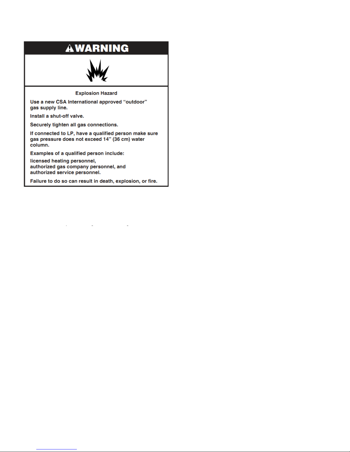
Gas Supply Requirements
CSA B149.1, Propane Storage And Handling Code, B149
CSA B149.1, Propane Storage And Handling Code, B149.2, or
Observe all governing codes and ordinances.
IMPORTANT: This installation must conform with all local codes
and ordinances. In the absence of local codes, installation must
conform with either the National Fuel Gas Code, ANSI
Z223.1/NFPA54, Natural Gas and Propane Installation Code,
.2, or
the Standard for Recreational Vehicles, ANSI A119.2/NFPA
1192 and CSA Z240 RV Series Recreational Vehicle Code as
applicable.
IMPORTANT: Grill must be connected to a regulated gas supply.
Refer to the model/serial rating plate for information on the type
of gas that can be used. If this information does not agree with
the type of gas available, check with your local gas supplier.
Gas Conversion:
No attempt shall be made to convert the grill from the gas
specified on the model/serial rating plate for use with a different
gas type without consulting the serving gas supplier. The
conversion kit supplied with grill must be used. See “Gas
Conversions” section for instructions.
Gas Pressure Regulator
The gas pressure regulator supplied with this grill must be used.
The inlet (supply) pressure to the regulator should be as follows
for proper operation:
LP Gas:
Operating pressure: 11" (27.9 cm) WCP
Inlet (supply) pressure: 11" to 14" (27.9 cm to 35.5 cm) WCP
Natural Gas:
Operating pressure: 4" (10.2 cm) WCP
Inlet (supply) pressure: 7" to 14" (17.8 cm to 35.5 cm) WCP
maximum.
Contact local gas supplier if you are not sure about the inlet
(supply) pressure.
7
Any brand of 20 lb LP gas fuel tank is acceptable f
Burner Requirements for High Altitude
Any brand of 20 lb LP gas fuel tank is acceptable for use with the
3. Place the 20 lb LP gas fuel tank bottom collar into the
mounting hole in the tank tray.
Input ratings shown on the model/serial rating plate are for
elevations up to 2,000 ft (609.6 m).
For elevations above 2,000 ft (609.6 m), ratings are reduced at a
rate of 4% for each 1,000 ft (304.8 m) above sea level. Orifice
conversion is required. See “Assistance” section to order.
Gas Supply Line Pressure Testing
Testing above 1/2 psi (3.5 kPa) or 14" (35.5 cm) WCP (gauge):
The grill and its individual shutoff valve must be disconnected
from the gas supply piping system during any pressure testing of
that system at test pressures greater than 1/2 psi (3.5 kPa).
Testing below 1/2 psi (3.5 kPa) or 14" (35.5 cm) WCP (gauge)
or lower:
The grill must be isolated from the gas supply piping system by
closing its individual manual shutoff valve during any pressure
testing of the gas supply piping system at test pressures equal to
or less than 1/2 psi (3.5 kPa).
Gas Connection Requirements
20 lb LP Gas Fuel Tank
This grill is equipped for use with a 20 lb LP gas fuel tank (fuel
tank not supplied). A gas pressure regulator/hose assembly is
supplied.
or use with the
grill, provided that it is compatible with the grill’s retention means
(tank tray included).
It is also design-certified by CSA International for local LP gas
supply or for Natural gas with appropriate conversion.
A
A. Gas pressure regulator/hose assembly
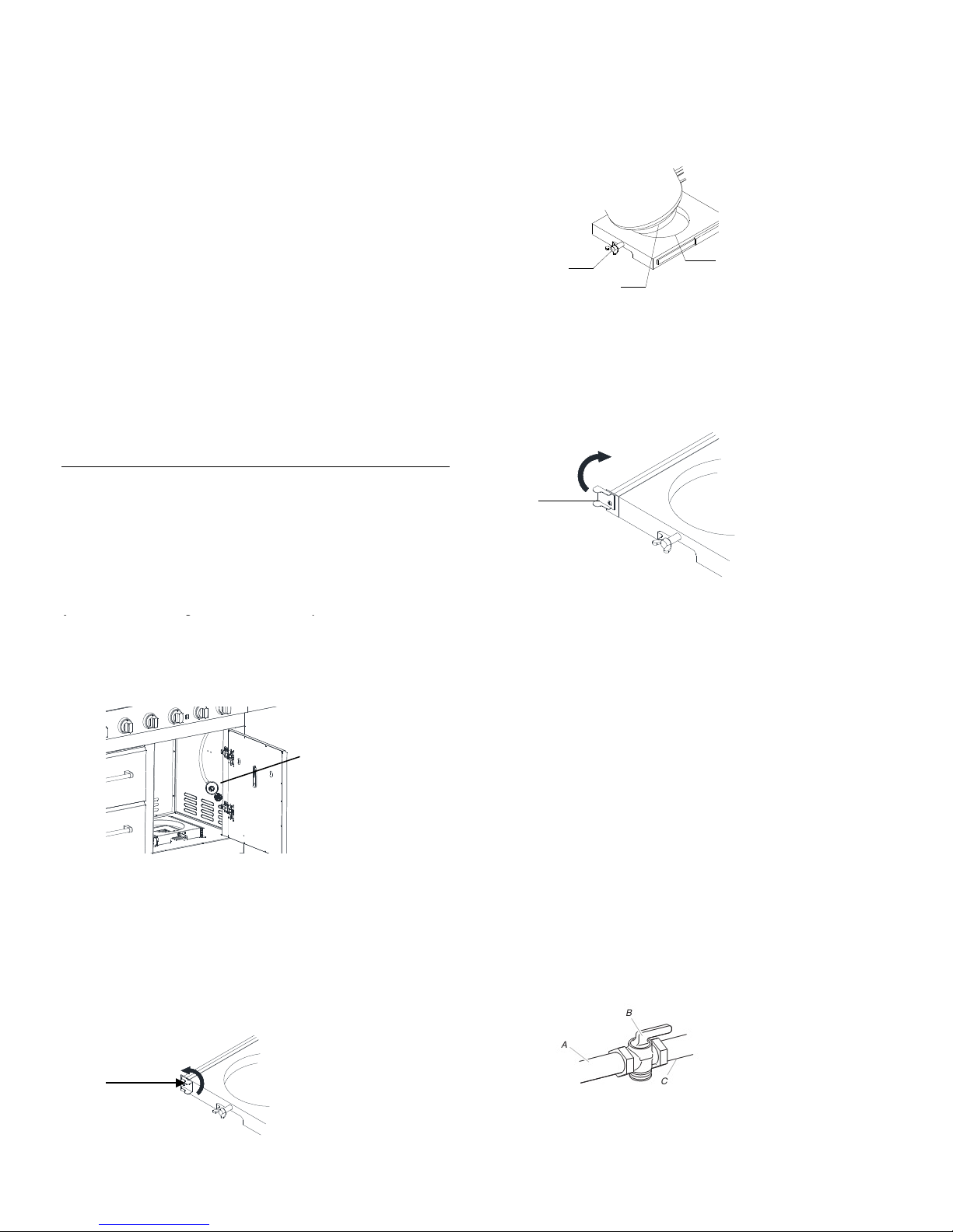
The 20 lb LP gas fuel tank must be mounted and secured.
Door style Tank Tray
1. Open cabinet doors.
4. Tighten the locking screw against the bottom collar of the
Natural Gas Conversion 20 lb LP gas fuel tank to secure.
B
A
C
A. Locking screw
B. Mounting hole
C. Bottom collar
5. Slide the drawer with the 20 lb LP gas fuel tank back into
the cabinet. Turn the tank tray locking bracket clockwise 90˚
to tighten.
A
A. Tank tray locking bracket
Natural Gas Conversion
The qualified Natural gas technician shall provide the Natural
gas supply to the selected grill location in accordance with the
National Fuel Gas Code ANSI Z223.1/NFPA 54 - latest edition,
and local codes. For conversion to Natural gas, the Natural Gas
Conversion Kit supplied with the grill (on some models) or the
Natural Gas Conversion Kit Part Number 710-0003 must be
used. See “Assistance” section for information on ordering.
IMPORTANT: The gas installation must conform with local
codes, or in the absence of local codes, with the National Fuel
Gas Code, ANSI Z223.1/NFPA 54 - latest edition.
Follow instructions for converting to Natural gas in the “Gas
Conversions” section of this manual or the instructions supplied
with Natural Gas Conversion Kit Part Number 710-0003.
The gas supply line shall be equipped with an approved shutoff
valve. This valve should be located in the same area as the grill
and should be in a location that allows ease of opening and
closing. Do not block access to the shutoff valve. The valve is
for turning on or shutting off gas to the grill.
2. Slide the tank tray locking bracket counterclockwise
90˚ and pull out the tray.
A
A. Tank tray locking bracket
8
A. Gas supply line
B. Shutoff valve “open” position
C. To grill
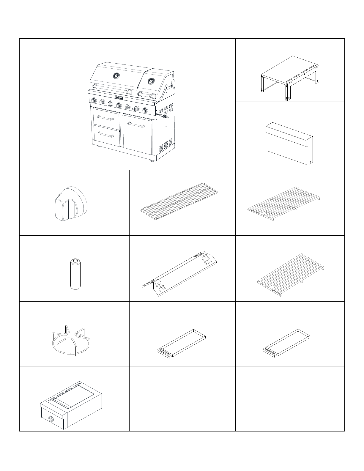
PACKAGE CONTENTS LIST
A. Firebox assembly-—1pc
B. Left side shelf—1pc
C. Side shelf control panel—
1pc
D. Control knob—1pc E. Warming rack—1pc F. Cooking grid with hole—3pcs
H. Flame Tamer—5pcsG. Battery—1pc I. Sear burner cooking grid --1pc
J. Side burner cooking grid --1pc K. Main burner grease tray– 1pc L. Sear burner grease tray– 1pc
M. Side burner bowl
assembly—1pc
9
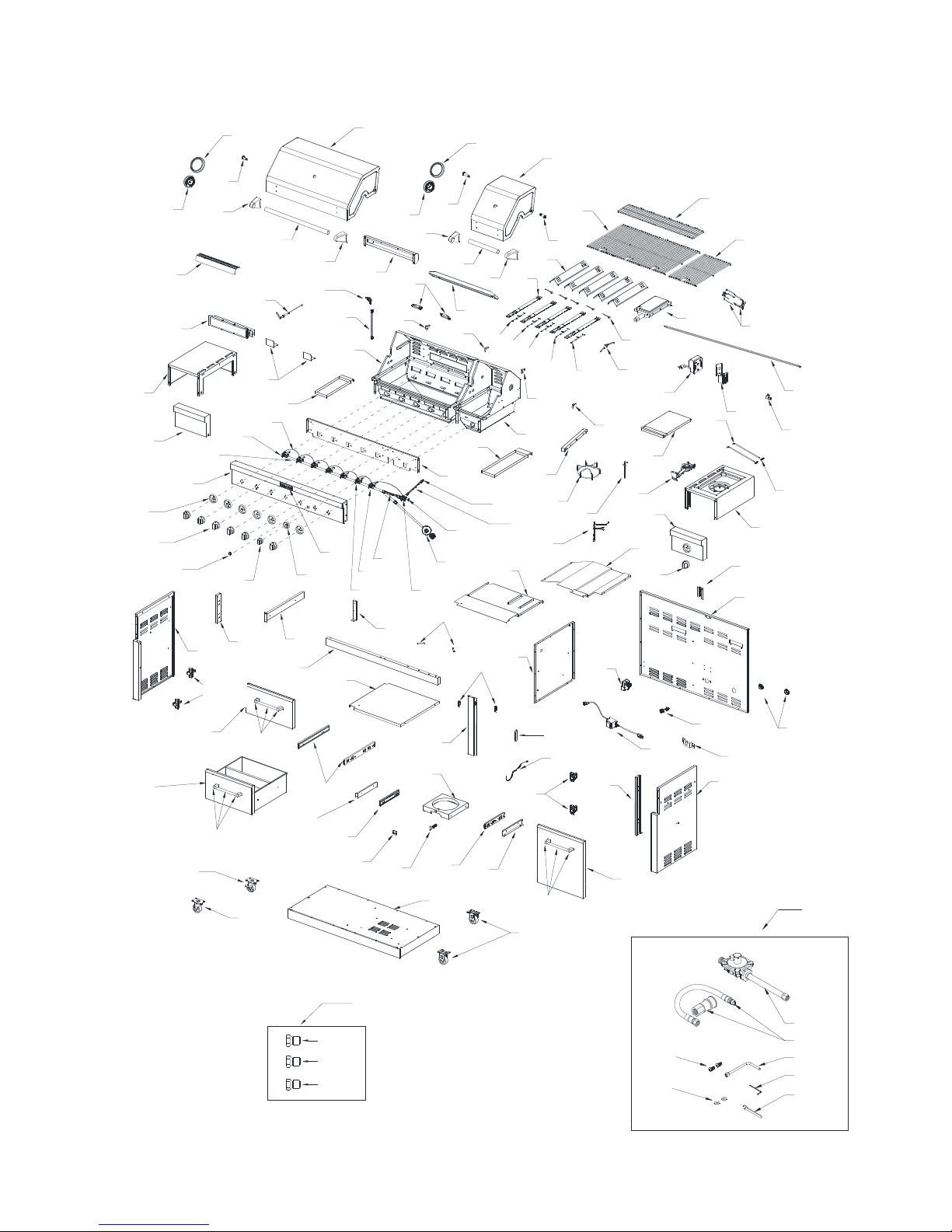
Replacement Parts
83
18
52
19
53
12
13
54
3
1
3
2
5
24
64
20
22
59
60
62
63
66
67
74
75
4
7
9
8
11
14
15
16
34
36
17
39
48
49
50
51
55
57
56
45
46
47
4
33
7
58
6
10
35
40
44
38
43
32
8
31
30
41
82
25
29
118
42
5
23
28 28
34
37
70
72
21
69
26
27
61
35
65
68
71
73
53
107
106
108
87
98
94
70
86
98
109
88
104
85
89
105
100
114
114a
114b
114c
103
84
101
102
91
100
110
90
99
81
94
111
98
92
93
80
95
97
79
113g
113f
77
78
96
NG Conversion Kit
76
113
113a
113b
113c
113d
113e
10
Part List
Rear burner ignition wire
Part
Number
1 Main lid 3 1 30 Main burner igniter wire C 1 1
2 Sear burner main lid 3 1 31 Main burner igniter wire D 1 1
3 Temperature gauge seat 1 2 32 Lamp case 1 1
4 Temperature gauge 1 2 33 Lamp 1 2
5 Main lid screw A 1 2 34 Main lid bracket seat, left 3 2
6 Main lid screw B 1 1 35 Main lid bracket seat, right 3 2
7 Main lid handle seat, left 1 2 36 Main burner bowl assembly
8 Main lid handle seat, right 1 2 37 Sear burner bowl assembly
9 Main lid handle tube 1 1 38 Sear burner grease tray 3 1
10 Sear main lid handle tube 1 1 39
11 Rear baffle 1 1 40 Front baffle 1 1
12 Rear burner heat shield 3 1 41
Part (description)
Warranty
Coverage
Quantity
Part
Number
Part description)
Main burner grease tray
Side burner orifice brass
connector
Warranty
Coverage
Nonreplaceable
Nonreplaceable
3 1
1 1
Quantity
1
1
13 Rear burner 1 1 42 Side burner flex gas line A 1 1
14
15
16 Rear burner flex gas line 1 1 45 Side Burner flex gas line B 1 1
17
18 Side shelf, left 3 1 47 Rear burner gas valve 1 1
19 Side shelf front panel, left 3 1 48 Igniter junction wire 1 1
20 Warming rack 3 1 49 Main gas valve 1 5
21 Cooking grid with hole 3 3 50 Main manifold 1 1
22
23 Flame tamer 3 5 52 Bezel 1 6
24 Sear burner 1 1 53 Knob 1 7
25 Main burner 10 5 54 Light switch 1 1
26 Burner pin assembly 1 5 55 Rear burner knob 1 1
Rear burner orifice with
brass elbow
Rotisserie burner igniter
bracket
Searing main burner
cooking grid
1 1 43 Side manifold 1 1
1 1 44 LP regulator 1 1
3 2 46 Sear burner gas valve 1 1
3 1 51 Main control panel 3 1
27 Sear burner ignition wire 1 1 56 Rear burner bezel 1 1
28 Main burner igniter wire A 1 2 57 Logo 1 1
29 Main burner igniter wire B 1 1 58 Side burner gas valve 1 1
11
Part
Number
59
Part (description)
Spit fork 1 2 94
Warranty
Coverage
Quantity
Part
Number
Part description)
Door hinge
Warranty
Coverage
1 4
Quantity
60
61
62
63 Shaft Collar 1 1 98 Door Handle 1 3
64
65
66 Side burner lid hinge rod pin 1 2 101 Tank bolt 1 1
67 Side burner bowl assembly 3 1 102 Gas tank tray 1 1
68 Side burner 1 1 103 Gas tank tray block piece 1 1
69 Side burner ignition wire 1 1 104 Gas tank tray slide bracket, left 1 1
70 Side burner cooking grid 3 1 105 Drawer slide 1 2
71
72 Lamp cord 1 1 107 Drawer 3 1
73 Heat shield, right 1 1 108
74 Igniter wire cover A 1 1 109
75 Rear panel 1 1 110 Bottom panel 1 1
Spit rod 1 1 95 Door hinge support bracket 1 1
Rotisserie motor 1 1 96 Side panel, right 1 1
Rotisserie motor bracket 3 1 97 Door 3 1
Side burner lid hinge rod 1 2 99 Gas tank tray slide bracket, right 1 1
Side burner lid 3 1 100 Gas tank tray slide 1 2
Side burner front panel
3 1 106 Small door 3 1
Swivel caster with brake
Swivel caster
1 1
1 1
76
77
78
79 Transformer 1 1 113a NG regulator assembly for NG unit 1
80
81
82
83
84
85 Drawer support piece 1 1 113f
86 Small door support piece 1 1 114 NG orifice pack 1
87 Side panel, left 1 1
88 Cart frame 1 1 114b Rear burner NG orifice (1.84mm) 1
89 Clapboard A 1 1 114c Sear burner NG orifice (1.98mm) 1
Rubber grommet
Power cord buckle
Igniter wire cover B
Electronic igniter modular
Clapboard B
Heat shield, left
Door hinge support bracket
strengthen piece
Firebox support piece A
1 2 111
1 1 112
1 1 113
1 1 113b
1 1 113c
1 1 113d
1 2 113e
3 1 113g
114a
Caster
Manual
NG conversion Kit
NG Gas Hose with Quick Connector
assembly for NG unit
6mm Nut Driver
Hex Wrench
6mm Wrench
Truss Head Screw
Flat Washer
Side burner NG orifice (1.7mm)
1 2
NG conversion kit sold
separately as a set
1
1
1
1
2
2
1
90 Door magnet 1 2 Preassembly hardware pack 1
91 Cart frame, middle 3 1 1
92
93 Lighting Rod 1 1
12
Lighting rod cover
1 1
118
Firebox connecting bracket
 Loading...