


INSTALLATION
INSTRUCTIONS
Commercial Dryer
Gas
INSTRUCTIONS D’INSTALLATION
Sèche-linge commercial À gaz
INSTRUCCIONES DE INSTALACIÓN
Secadora comercial A gas
ISTRUZIONI
D’INSTALLAZIONE
Asciugatrice commerciale A gas
MLG27PN
MLG27PD
www.maytagcommerciallaundry.com
W10722015D
TABLE OF CONTENTS
. |
Page |
Dryer Safety............................................................................. |
3 |
Dryer Disposal......................................................................... |
6 |
Tools & Parts ........................................................................... |
7 |
Specifications........................................................................... |
7 |
Dimensions/Clearances ........................................................ |
8 |
Installation Requirements ..................................................... |
9 |
Venting Requirements ......................................................... |
12 |
Gas Supply Requirements ................................................... |
14 |
Installing Leveling Legs ....................................................... |
15 |
Leveling ................................................................................. |
16 |
Complete Installation ........................................................... |
17 |
Reversing Door Swing (optional)......................................... |
18 |
Maintenance Instructions .................................................... |
19 |
If You Need Assistance ........................................................ |
19 |
Technical Specifications – Gas Dryer ................................. |
20 |
Electronic Control Setup Instructions ................................ |
22 |
Warranty ................................................................................ |
27 |
TABLE DES MATIÈRES
. |
Page |
Sécurité du sèche-linge......................................................... |
28 |
Élimination du sèche-linge.................................................... |
31 |
Outils et pièces ...................................................................... |
32 |
Spécifications ........................................................................ |
32 |
Dimensions/Distances de dégagement .............................. |
33 |
Exigences d’installation ........................................................ |
34 |
Exigences concernant l’évacuation .................................... |
35 |
Spécifications de l’alimentation en gaz .............................. |
40 |
Installation des pieds de nivellement................................... |
41 |
Nivellement ............................................................................ |
42 |
Achever l’installation ............................................................ |
43 |
Inversion du sens d’ouverture de la porte (facultatif)......... |
44 |
Instructions d’entretien ........................................................ |
45 |
Si vous avez besoin d’assistance ........................................ |
45 |
Fiche technique – sèche-linge à gaz ................................... |
45 |
Instructions de réglage du tableau |
|
de commande électronique ................................................. |
48 |
Garantie ................................................................................. |
54 |
ÍNDICE
. |
Página |
Seguridad de la secadora..................................................... |
56 |
Eliminación de la secadora................................................... |
58 |
Herramientas y piezas........................................................... |
59 |
Especificaciones..................................................................... |
59 |
Dimensiones y espacios libres ............................................ |
60 |
Requisitos de instalación...................................................... |
61 |
Requisitos de ventilación ..................................................... |
64 |
Requisitos del suministro de gas ........................................ |
67 |
Instalación de las patas niveladoras.................................... |
68 |
Nivelación .............................................................................. |
69 |
Complete la instalación ........................................................ |
70 |
Cómo invertir el cierre de la puerta (opcional) ................... |
71 |
Instrucciones de mantenimiento.......................................... |
72 |
Si necesita ayuda .................................................................. |
72 |
Especificaciones técnicas – secadora a gas ..................... |
73 |
Instrucciones de programación |
|
del control electrónico .......................................................... |
75 |
Garantía ................................................................................. |
81 |
INDICE
. |
Pagina |
Sicurezza dell’asciugatrice.................................................. |
82 |
Eliminazione dell’asciugatrice............................................. |
85 |
Attrezzi e componenti .......................................................... |
86 |
Specifiche ............................................................................. |
86 |
Dimensioni/spazi .................................................................. |
87 |
Requisiti dell’installazione ................................................... |
88 |
Requisiti di scarico .............................................................. |
91 |
Requisiti di alimentazione del gas ...................................... |
93 |
Installazione dei piedini di regolazione............................... |
94 |
Livellamento ......................................................................... |
95 |
Completamento dell’installazione ...................................... |
96 |
Inversione della rotazione di apertura (facoltativo) .......... |
97 |
Istruzioni di manutenzione................................................... |
98 |
Se avete bisogno dell’assistenza ....................................... |
98 |
Dati tecnici – asciugatrice a gas ......................................... |
99 |
Configurazione dei controlli elettronici ............................ |
101 |
Garanzia .............................................................................. |
107 |
2

DRYER SAFETY
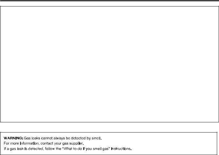
nIt is recommended that the owner post, in a prominent location, instructions for the customer’s use in the event the customer smells gas. This information should be obtained from your gas supplier.
nPost the following warning in a prominent location.
CAUTION – RISK OF FIRE/FLAMMABLE MATERIALS
This is an additional safety alert symbol that alerts you to the risk of re.
FOR YOUR SAFETY
1.DO NOT USE OR STORE PETROL OR OTHER FLAMMABLE MATERIALS IN THIS APPLIANCE OR NEAR THIS APPLIANCE.
2.DO NOT SPRAY AEROSOLS IN THE VICINITY OF THIS APPLIANCE WHILE IT IS IN OPERATION.
3.DO NOT MODIFY THIS APPLIANCE.
3
DRYER SAFETY
 WARNING:
FIRE OR EXPLOSION HAZARD
Failure to follow safety warnings exactly could result in serious injury, death or property damage.
–Do not store or use gasoline or other flammable vapors and liquids in the vicinity of this or any other appliance.
–WHAT TO DO IF YOU SMELL GAS:
•Do not try to light any appliance.
•Do not touch any electrical switch; do not use any phone in your building.
•Clear the room, building, or area of all occupants.
•Immediately call your gas supplier from a neighbor's phone. Follow the gas supplier's instructions.
•If you cannot reach your gas supplier, call the fire department.
–Installation and service must be performed by a qualified installer, service agency, or the gas supplier.
4

DRYER SAFETY
IMPORTANT SAFETY INSTRUCTIONS
WARNING: To reduce the risk of fire, electric shock, or injury to persons when using the dryer, follow basic precautions, including the following:
n Read all instructions before using |
|
|
|
|
n |
Do not install or store the dryer where it will be exposed |
|
|
|
|
|
||||
the dryer. |
|
|
|
|
|
to the weather. |
|
|
|
|
|
|
|||
n This dryer is intended only for drying clothes and textiles |
n |
Do not tamper with controls. |
|||||
that have been washed in water. Do not use for any other |
n |
Clean dryer lint screen before or after each load. |
|||||
purpose. |
|||||||
n |
Do not use this dryer without the lint screen in place. |
||||||
n WARNING: If you smell gas, do not use the dryer or any |
|||||||
n |
Do not repair or replace any part of the dryer or attempt |
||||||
electrical equipment nearby. Warn other people to clear |
|||||||
|
any servicing unless specifically recommended in |
||||||
the area. Contact the dryer owner immediately. |
|
||||||
|
this Use and Care Guide or in published user-repair |
||||||
n Do not place items exposed to cooking oils in your dryer. |
|
||||||
|
instructions that you understand and have the skills |
||||||
Items contaminated with cooking oils may contribute to |
|
||||||
|
to carry out. |
||||||
a chemical reaction that could cause a load to catch fire. |
|
||||||
n |
Do not use fabric softeners or products to eliminate static |
||||||
To reduce the risk of fire due to contaminated loads, the |
|||||||
|
unless recommended by the manufacturer of the fabric |
||||||
final part of a tumble dryer cycle occurs without heat |
|
||||||
|
softener or product. |
||||||
(cool down period). Avoid stopping a tumble dryer before |
|
||||||
|
Do not use heat to dry articles containing foam rubber |
||||||
the end of the drying cycle unless all items are quickly |
n |
||||||
removed and spread out so that the heat is dissipated. |
|
or similarly textured rubber-like materials. |
|||||
n If it is unavoidable that fabrics that contain vegetable or |
n |
The final part of a tumble dryer cycle occurs without |
|||||
cooking oil or that have been contaminated by hair care |
|
heat (cool-down cycle) to ensure that the articles are left |
|||||
products be placed in a tumble dryer, they should first |
|
at a temperature that ensures that the items will not be |
|||||
be washed in hot water with extra detergent – this will |
|
damaged. |
|||||
reduce, but not eliminate the hazard. |
n |
WARNING: Never stop a tumble dryer before the end |
|||||
n Do not dry articles that have been previously |
|
of the drying cycle unless all items are quickly removed |
|||||
cleaned in, washed in, soaked in, or spotted with petrol, |
|
and spread out so that the heat is dissipated. (Avoids risk |
|||||
dry-cleaning solvents, other flammable, or explosive |
|
of spontaneous combustion). |
|||||
substances as they give off vapors that could ignite |
n |
In case of electrical supply failure, remove the load |
|||||
or explode. |
|
quickly and spread it out to avoid risk of spontaneous |
|||||
n Items that have been soiled with substances such |
|
combustion. |
|||||
as acetone, alcohol, petrol, kerosene, spot removers, |
n |
Keep area around the exhaust opening and adjacent |
|||||
turpentine, waxes, and wax removers should be washed |
|
surrounding areas free from the accumulation of lint, dust, |
|||||
in hot water with extra detergent before being dried in |
|
and dirt. |
|||||
the dryer. |
n |
The fresh air ventilation openings into the room and into |
|||||
n Do not dry unwashed items in the dryer. |
|||||||
|
the dryer must not be blocked or sealed. |
||||||
n Do not use this dryer if industrial chemicals have been |
n |
Emergency stop control: After installation, access to |
|||||
used for cleaning. The possible presence of residual |
|
mains plug or disconnection from mains supply via a |
|||||
quantities of aggressive or decomposed chemicals in |
|
double-pole switch must be ensured at all times in order |
|||||
the load may produce damage to the dryer and harmful |
|
to ensure immediate deactivation of the dryer in case of |
|||||
fumes. |
|
emergency. |
|||||
n Do not allow children to play on or in the dryer. Close |
n |
The interior of the dryer and dryer exhaust vent should be |
|||||
supervision of children is necessary when the dryer is |
|
cleaned periodically by qualified service personnel. |
|||||
used near children. |
n |
See “Electrical Requirements” section for earthing |
|||||
n This dryer is not intended for use by persons (including |
|||||||
|
instructions. |
||||||
children) with reduced physical, sensory, or mental |
n |
The dryer shall be disconnected from its power source |
|||||
capabilities, or lack of experience or knowledge, |
|||||||
|
during service and when replacing parts. If the removal |
||||||
unless they have been given supervision or instruction |
|
||||||
|
of the plug is foreseen, it shall be clearly indicated that it |
||||||
concerning use of the dryer by a person responsible |
|
||||||
|
be possible for the operator to confirm the removal of the |
||||||
for their safety. |
|
||||||
|
plug from any point of access. |
||||||
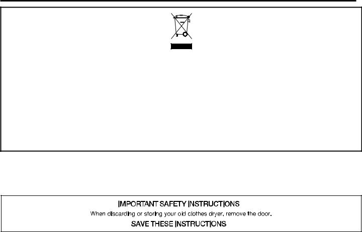
n Before the dryer is removed from service or discarded, |
|
||||||
|
If this is not possible due to the construction of the |
||||||
remove the door to the dryer compartment. |
|
||||||
|
appliance or its installation, a disconnection with a |
||||||
n Do not reach into the dryer if the drum is moving. |
|
||||||
|
locking system in the isolated position shall be provided. |
||||||
nOpening the dryer door will stop the function of the dryer.
nWhen loading or re-loading the dryer, avoid touching hot metal parts of the drum (burn risk).
nIf drum rotation is blocked due to trapped textiles, disconnect the dryer from the electrical supply before gently removing the blockage.
nIf the dryer is not heating, or appears to be defective or damaged, do not use it. Contact the owner.
SAVE THESE INSTRUCTIONS
5
DRYER DISPOSAL
This appliance is marked according to the European directive 2012/19/EU on Waste Electrical and Electronic Equipment (WEEE).
By ensuring this product is disposed of correctly, you will help avoid potential negative consequences for the environment and human health, which could otherwise be caused by inappropriate waste handling of this product.
The symbol on the product, or on the documents accompanying the product, indicates that this appliance may not be treated as household waste. Instead it shall be handed over to the applicable collection point for the recycling of electrical and electronic equipment.
Disposal must be carried out in accordance with local environmental regulations for waste disposal.
For more detailed information about treatment, recovery and recycling of this product, please contact your local city ofƒce, your household waste disposal service or the shop where you purchased the product.
MODEL NOMENCLATURE:
MLG – Maytag Dryer – Gas PN – Electronic Control – Non-Pay
## (e.g. 27) – Model Type Number PD – Electronic Control – Coin Drop Enabled
6
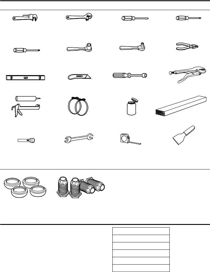
TOOLS & PARTS
Tools Needed:
203 mm (8") |
203 mm (8") or 254 mm (10") |
Flat-blade screwdriver |
Phillips screwdriver |
or 254 mm (10") |
Adjustable wrench |
|
|
Pipe wrench |
that opens to 25 mm (1") |
|
|
TORX T20† Security |
25 mm (1") Hex-head |
8 mm (5/16") Socket wrench |
Pliers |
screwdriver or bit |
socket wrench |
|
(that open to 39 mm [19/16"]) |
Level |
Utility knife |
6 mm (1/4") Nut driver |
Locking pliers |
Caulk gun and caulk |
Vent clamps |
Pipe-joint compound |
686 mm (27") Wood block |
(for installing new exhaust vent) |
|
suitable for gas type |
|
Flashlight (optional) |
13 mm (1/2") and 14 mm |
Ruler or measuring tape |
Putty knife |
|
(9/16") Open-end wrenches |
|
|
Parts Supplied:
Foot boots (4) |
Leveling legs (4) |
NOTE: The circuit diagram for this dryer is located inside the lower front panel, within the Tech Sheets.
SPECIFICATIONS
These units are sold in multiple regions with different requirements for measuring capacity. Below are a few of the valid forms of measure posted on this product:
Dry Linen Capacity: A weight measure that reflects a minimum threshold for dry volume capacity that is needed for import tariff purposes.
IEC Capacity: The capacity measure that represents the maximum capacity of dry linens and textiles which the manufacturer declares can be treated in a specific cycle.
Dry Linen Capacity
10.5 Kg (23 lb)
IEC Capacity
9 Kg (20 lb)
Sound Level
LpA: 58 dB(A) (Kpa+/-10 dB(A))
†TORX and T20 are trademarks of Acument Intellectual Properties, LLC.
7
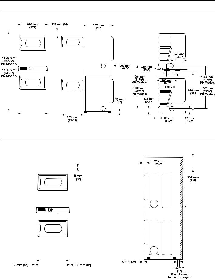
DIMENSIONS/CLEARANCES
Dimensions
|
|
|
|
Front View |
|
|
|
Side View |
|
|
|
|
|
|
|
|
|
|
|
|
|
|
|
|
|
|
|
|
|
|
|
Back View |
|
|
|
|
|||||||||||||||||||||||||||||||||||
|
|
|
|
|
|
|
|
|
|
|
|
|
|
|
|
|
|
|
|
|
|
|
|
|
|
|
|
|
|
|
|
|
|
|
|
|
|
|
|
|
|
|
|
|
|
|
|
|
|
|
|
|
|
|
|
|
|
|
|
|
|
|
|
|
|
|
|
|
|
|
|
|
|
|
|
|
|
|
|
|
|
|
|
|
|
|
|
|
|
|
|
|
|
|
|
|
|
|
|
|
|
|
|
|
|
|
|
|
|
|
|
|
|
|
|
|
|
|
|
|
|
|
|
|
|
|
|
|
|
|
|
|
|
|
|
|
|
|
|
|
|
|
|
|
|
|
|
|
|
|
|
|
|
|
|
|
|
|
|
|
|
|
|
|
|
|
|
|
|
|
|
|
|
|
|
|
|
|
|
|
|
|
|
|
|
|
|
|
|
|
|
|
|
|
|
|
|
|
|
|
|
|
|
|
|
|
|
|
|
|
|
|
|
|
|
|
|
|
|
|
|
|
|
|
|
|
|
|
|
|
|
|
|
|
|
|
|
|
|
|
|
|
|
|
|
|
|
|
|
|
|
|
|
|
|
|
|
|
|
|
|
|
|
|
|
|
|
|
|
|
|
|
|
|
|
|
|
|
|
|
|
|
|
|
|
|
|
|
|
|
|
|
|
|
|
|
|
|
|
|
|
|
|
|
|
|
|
|
|
|
|
|
|
|
|
|
|
|
|
|
|
|
|
|
|
|
|
|
|
|
|
|
|
|
|
|
|
|
|
|
|
|
|
|
|
|
|
|
|
|
|
|
|
|
|
|
|
|
|
|
|
|
|
|
|
|
|
|
|
|
|
|
|
|
|
|
|
|
|
|
|
|
|
|
|
|
|
|
|
|
|
|
|
|
|
|
|
|
|
|
|
|
|
|
|
|
|
|
|
|
|
|
|
|
|
|
|
|
|
|
|
|
|
|
|
|
|
|
|
|
|
|
|
|
|
|
|
|
|
|
|
|
|
|
|
|
|
|
|
|
|
|
|
|
|
|
|
|
|
|
|
|
|
|
|
|
|
|
|
|
|
|
|
|
|
|
|
|
|
|
|
|
|
|
|
|
|
|
|
|
|
|
|
|
|
|
|
|
|
|
|
|
|
|
|
|
|
|
|
|
|
|
|
|
|
|
|
|
|
|
|
|
|
|
|
|
|
|
|
|
|
|
|
|
|
|
|
|
|
|
|
|
|
|
|
|
|
|
|
|
|
|
|
|
|
|
|
|
|
|
|
|
|
|
|
|
|
|
|
|
|
|
|
|
|
|
|
|
|
|
|
|
|
|
|
|
|
|
|
|
|
|
|
|
|
|
|
|
|
|
|
|
|
|
|
|
|
|
|
|
|
|
|
|
|
|
|
|
|
|
|
|
|
|
|
|
|
|
|
|
|
|
|
|
|
|
|
|
|
|
|
|
|
|
|
|
|
|
|
|
|
|
|
|
|
|
|
|
|
|
|
|
|
|
|
|
|
|
|
|
|
|
|
|
|
|
|
|
|
|
|
|
|
|
|
|
|
|
|
|
|
|
|
|
|
|
|
|
|
|
|
|
|
|
|
|
|
|
|
|
|
|
|
|
|
|
|
|
|
|
|
|
|
|
|
|
|
|
|
|
|
|
|
|
|
|
|
|
|
|
|
|
|
|
|
|
|
|
|
|
|
|
|
|
|
|
|
|
|
|
|
|
|
|
|
|
|
|
|
|
|
|
|
|
|
|
|
|
|
|
|
|
|
|
|
|
|
|
|
|
|
|
|
|
|
|
|
|
|
|
|
|
|
|
|
|
|
|
|
|
|
|
|
|
|
|
|
|
|
|
|
|
|
|
|
|
|
|
|
|
|
|
|
|
|
|
|
|
|
|
|
|
|
|
|
|
|
|
|
|
|
|
|
|
|
|
|
|
|
|
|
|
|
|
|
|
|
|
|
|
|
|
|
|
|
|
|
|
|
|
|
|
|
|
|
|
|
|
|
|
|
|
|
|
|
|
|
|
|
|
|
|
|
|
|
|
|
|
|
|
|
|
|
|
|
|
|
|
|
|
|
|
|
|
|
|
|
|
|
|
|
|
|
|
|
|
|
|
|
|
|
|
|
|
|
|
|
|
|
|
|
|
|
|
|
|
|
|
|
|
|
|
|
|
|
|
|
|
|
|
|
|
|
|
|
|
|
|
|
|
|
|
|
|
|
|
|
|
|
|
|
|
|
|
|
|
|
|
|
|
|
|
|
|
|
|
|
|
|
|
|
|
|
|
|
|
|
|
|
|
|
|
|
|
|
|
|
|
|
|
|
|
|
|
|
|
|
|
|
|
|
|
|
|
|
|
|
|
|
|
|
|
|
|
|
|
|
|
|
|
|
|
|
|
|
|
|
|
|
|
|
|
|
|
|
|
|
|
|
|
|
|
|
|
|
|
|
|
|
|
|
|
|
|
|
|
|
|
|
|
|
|
|
|
|
|
|
|
|
|
|
|
|
|
|
|
|
|
|
|
|
|
|
|
|
|
|
|
|
|
|
|
|
|
|
|
|
|
|
|
|
|
|
|
|
|
|
|
|
|
|
|
|
|
|
|
|
|
|
|
|
|
|
|
|
|
|
|
|
|
|
|
|
|
|
|
|
|
|
|
|
|
|
|
|
|
|
|
|
|
|
|
|
|
|
|
|
|
|
|
|
|
|
|
|
|
|
|
|
|
|
|
|
|
|
|
|
|
|
|
|
|
|
|
|
|
|
|
|
|
|
|
|
|
|
|
|
|
|
|
|
|
|
|
|
|
|
|
|
|
|
|
|
|
|
|
|
|
|
|
|
|
|
|
|
|
|
|
|
|
|
|
|
|
|
|
|
|
|
|
|
|
|
|
|
|
|
|
|
|
|
|
|
|
|
|
|
|
|
|
|
|
|
|
|
|
|
|
|
|
|
|
|
|
|
|
|
|
|
|
|
|
|
|
|
|
|
|
|
|
|
|
|
|
|
|
|
|
|
|
|
|
|
|
|
|
|
|
|
|
|
|
|
|
|
|
|
|
|
|
|
|
|
|
|
|
|
|
|
|
|
|
|
|
|
|
|
|
|
|
|
|
|
|
|
|
|
|
|
|
|
|
|
|
|
|
|
|
|
|
|
|
|
|
|
|
|
|
|
|
|
|
|
|
|
|
|
|
|
|
|
|
|
|
|
|
|
|
|
|
|
|
|
|
|
|
|
|
|
|
|
|
|
|
|
|
|
|
|
|
|
|
|
|
|
|
|
|
|
|
|
|
|
|
|
|
|
|
|
|
|
|
|
|
|
|
|
|
|
|
|
|
|
|
|
|
|
|
|
|
|
|
|
|
|
|
|
|
|
|
|
|
|
|
|
|
|
|
|
|
|
|
|
|
|
|
|
|
|
|
|
|
|
|
|
|
|
|
|
|
|
|
|
|
|
|
|
|
|
|
|
|
|
|
|
|
|
|
|
|
|
|
|
|
|
|
|
|
|
|
|
|
|
|
|
|
|
|
|
|
|
|
|
|
|
|
|
|
|
|
|
|
|
|
|
|
|
|
|
|
|
|
|
|
|
|
|
|
|
|
|
|
|
|
|
|
|
|
|
|
|
|
|
|
|
|
|
|
|
|
|
|
|
|
|
|
|
|
|
|
|
|
|
|
|
|
|
|
|
|
|
|
|
|
|
|
|
|
|
|
|
|
|
|
|
|
|
|
|
|
|
|
|
|
|
|
|
|
|
|
|
|
|
|
|
|
|
|
|
|
|
|
|
|
|
|
|
|
|
|
|
|
|
|
|
|
|
|
|
|
|
|
|
|
|
|
|
|
|
|
|
|
|
|
|
|
|
|
|
|
|
|
|
|
|
|
|
|
|
|
|
|
|
|
|
|
|
|
|
|
|
|
|
|
|
|
|
|
|
|
|
|
|
|
|
|
|
|
|
|
|
|
|
|
|
|
|
|
|
|
|
|
|
|
|
|
|
|
|
|
|
|
|
|
|
|
|
|
|
|
|
|
|
|
|
|
|
|
|
|
|
|
|
|
|
|
|
|
|
|
|
|
|
|
|
|
|
|
|
|
|
|
|
|
|
|
|
|
|
|
|
|
|
|
|
|
|
|
|
|
|
|
|
|
|
|
|
|
|
|
|
|
|
|
|
|
|
|
|
|
|
|
|
|
|
|
|
|
|
|
|
|
|
|
|
|
|
|
|
|
|
|
|
|
|
|
|
|
|
|
|
|
|
|
|
|
|
|
|
|
|
|
|
|
|
|
|
|
|
|
|
|
|
|
|
|
|
|
|
|
|
|
|
|
|
|
|
|
|
|
|
|
|
|
|
|
|
|
|
|
|
|
|
|
|
|
|
|
|
|
|
|
|
|
|
|
|
|
|
|
|
|
|
|
|
|
|
|
|
|
|
|
|
|
|
|
|
|
|
|
|
|
|
|
|
|
|
|
|
|
|
|
|
|
|
|
|
|
|
|
|
|
|
|
|
|
|
|
|
|
|
|
|
|
|
|
|
|
|
|
|
|
|
|
|
|
|
|
|
|
|
|
|
|
|
|
|
|
|
|
|
|
|
|
|
|
|
|
|
|
|
|
|
|
|
|
|
|
|
|
|
|
|
|
|
|
|
|
|
|
|
|
|
|
|
|
|
|
|
|
|
|
|
|
|
|
|
|
|
|
|
|
|
|
|
|
|
|
|
|
|
|
|
|
|
|
|
|
|
|
|
|
|
|
|
|
|
|
|
|
|
|
|
|
|
|
|
|
|
|
|
|
|
|
|
|
|
|
|
|
|
|
|
|
|
|
|
|
|
|
|
|
|
|
|
|
|
|
|
|
|
|
|
|
|
|
|
|
|
|
|
|
|
|
|
|
|
|
|
|
|
|
|
|
|
|
|
|
|
|
|
|
|
|
|
|
|
|
|
|
|
|
|
|
|
|
|
|
|
|
|
|
|
|
|
|
|
|
|
|
|
|
|
|
|
|
|
|
|
|
|
|
|
|
|
|
|
|
|
|
|
|
|
|
|
|
|
|
|
|
|
|
|
|
|
|
|
|
|
|
|
|
|
|
|
|
|
|
|
|
|
|
|
|
|
|
|
|
|
|
|
|
|
|
|
|
|
|
|
|
|
|
|
|
|
|
|
|
|
|
|
|
|
|
|
|
|
|
|
|
|
|
|
|
|
|
|
|
|
|
|
|
|
|
|
|
|
|
|
|
|
|
|
|
|
|
|
|
|
|
|
|
|
|
|
|
|
|
|
|
|
|
|
|
|
|
|
|
|
|
|
|
|
|
|
|
|
|
|
|
|
|
|
|
|
|
|
|
|
|
|
|
|
|
|
|
|
|
|
|
|
|
|
|
|
|
|
|
|
|
|
|
|
|
|
|
|
|
|
|
|
|
|
|
|
|
|
|
|
|
|
|
|
|
|
|
|
|
|
|
|
|
|
|
|
|
|
|
|
|
|
|
|
|
|
|
|
|
|
|
|
|
|
|
|
|
|
|
|
|
|
|
|
|
|
|
|
|
|
|
|
|
|
|
|
|
|
|
|
|
|
|
|
|
|
|
|
|
|
|
|
|
|
|
|
|
|
|
|
|
|
|
|
|
|
|
|
|
|
|
|
|
|
|
|
|
|
|
|
|
|
|
|
|
|
|
|
|
|
|
|
|
|
|
|
|
|
|
|
|
|
|
|
|
|
|
|
|
|
|
|
|
|
|
|
|
|
|
|
|
|
|
|
|
|
|
|
|
|
|
|
|
|
|
|
|
|
|
|
|
|
|
|
|
|
|
|
|
|
|
|
Minimum Clearances
Front View, Recessed Opening |
Side View, Recessed In Closet |
||||||||||||||||||||||||||||||||||||||||||
|
|
|
|
|
|
|
|
|
|
|
|
|
|
|
|
|
|
|
|
|
|
|
|
|
|
|
|
|
|
|
|
|
|
|
|
|
|
|
|
|
|
|
|
|
|
|
|
|
|
|
|
|
|
|
|
|
|
|
|
|
|
|
|
|
|
|
|
|
|
|
|
|
|
|
|
|
|
|
|
|
|
|
|
|
|
|
|
|
|
|
|
|
|
|
|
|
|
|
|
|
|
|
|
|
|
|
|
|
|
|
|
|
|
|
|
|
|
|
|
|
|
|
|
|
|
|
|
|
|
|
|
|
|
|
|
|
|
|
|
|
|
|
|
|
|
|
|
|
|
|
|
|
|
|
|
|
|
|
|
|
|
|
|
|
|
|
|
|
|
|
|
|
|
|
|
|
|
|
|
|
|
|
|
|
|
|
|
|
|
|
|
|
|
|
|
|
|
|
|
|
|
|
|
|
|
|
|
|
|
|
|
|
|
|
|
|
|
|
|
|
|
|
|
|
|
|
|
|
|
|
|
|
|
|
|
|
|
|
|
|
|
|
|
|
|
|
|
|
|
|
|
|
|
|
|
|
|
|
|
|
|
|
|
|
|
|
|
|
|
|
|
|
|
|
|
|
|
|
|
|
|
|
|
|
|
|
|
|
|
|
|
|
|
|
|
|
|
|
|
|
|
|
|
|
|
|
|
|
|
|
|
|
|
|
|
|
|
|
|
|
|
|
|
|
|
|
|
|
|
|
|
|
|
|
|
|
|
|
|
|
|
|
|
|
|
|
|
|
|
|
|
|
|
|
|
|
|
|
|
|
|
|
|
|
|
|
|
|
|
|
|
|
|
|
|
|
|
|
|
|
|
|
|
|
|
|
|
|
|
|
|
|
|
|
|
|
|
|
|
|
|
|
|
|
|
|
|
|
|
|
|
|
|
|
|
|
|
|
|
|
|
|
|
|
|
|
|
|
|
|
|
|
|
|
|
|
|
|
|
|
|
|
|
|
|
|
|
|
|
|
|
|
|
|
|
|
|
|
|
|
|
|
|
|
|
|
|
|
|
|
|
|
|
|
|
|
|
|
|
|
|
|
|
|
|
|
|
|
|
|
|
|
|
|
|
|
|
|
|
|
|
|
|
|
|
|
|
|
|
|
|
|
|
|
|
|
|
|
|
|
|
|
|
|
|
|
|
|
|
|
|
|
|
|
|
|
|
|
|
|
|
|
|
|
|
|
|
|
|
|
|
|
|
|
|
|
|
|
|
|
|
|
|
|
|
|
|
|
|
|
|
|
|
|
|
|
|
|
|
|
|
|
|
|
|
|
|
|
|
|
|
|
|
|
|
|
|
|
|
|
|
|
|
|
|
|
|
|
|
|
|
|
|
|
|
|
|
|
|
|
|
|
|
|
|
|
|
|
|
|
|
|
|
|
|
|
|
|
|
|
|
|
|
|
|
|
|
|
|
|
|
|
|
|
|
|
|
|
|
|
|
|
|
|
|
|
|
|
|
|
|
|
|
|
|
|
|
|
|
|
|
|
|
|
|
|
|
|
|
|
|
|
|
|
|
|
|
|
|
|
|
|
|
|
|
|
|
|
|
|
|
|
|
|
|
|
|
|
|
|
|
|
|
|
|
|
|
|
|
|
|
|
|
|
|
|
|
|
|
|
|
|
|
|
|
|
|
|
|
|
|
|
|
|
|
|
|
|
|
|
|
|
|
|
|
|
|
|
|
|
|
|
|
|
|
|
|
|
|
|
|
|
|
|
|
|
|
|
|
|
|
|
|
|
|
|
|
|
|
|
|
|
|
|
|
|
|
|
|
|
|
|
|
|
|
|
|
|
|
|
|
|
|
|
|
|
|
|
|
|
|
|
|
|
|
|
|
|
|
|
|
|
|
|
|
|
|
|
|
|
|
|
|
|
|
|
|
|
|
|
|
|
|
|
|
|
|
|
|
|
|
|
|
|
|
|
|
|
|
|
|
|
|
|
|
|
|
|
|
|
|
|
|
|
|
|
|
|
|
|
|
|
|
|
|
|
|
|
|
|
|
|
|
|
|
|
|
|
|
|
|
|
|
|
|
|
|
|
|
|
|
|
|
|
|
|
|
|
|
|
|
|
|
|
|
|
|
|
|
|
|
|
|
|
|
|
|
|
|
|
|
|
|
|
|
|
|
|
|
|
|
|
|
|
|
|
|
|
|
|
|
|
|
|
|
|
|
|
|
|
|
|
|
|
|
|
|
|
|
|
|
|
|
|
|
|
|
|
|
|
|
|
|
|
|
|
|
|
|
|
|
|
|
|
|
|
|
|
|
|
|
|
|
|
|
|
|
|
|
|
|
|
|
|
|
|
|
|
|
|
|
|
|
|
|
|
|
|
|
|
|
|
|
|
|
|
|
|
|
|
|
|
|
|
|
|
|
|
|
|
|
|
|
|
|
|
|
|
|
|
|
|
|
|
|
|
|
|
|
8
INSTALLATION REQUIREMENTS
Location
Your dryer can be installed in a basement, laundry room, or recessed area.
Companion appliance location requirements should also be considered.
IMPORTANT: Do not install or store the dryer where it will be exposed to the weather. Proper installation is your responsibility.
You will need:
nA level floor with a maximum slope of 25 mm (1") under entire dryer. Installing the dryer on soft floor surfaces, such as carpets or surfaces with foam backing, is
not recommended.
nA sturdy and solid floor to support the dryer with a total weight (load) of 204 kg (450 lbs).
Installation clearances
nThe location must be large enough to allow the dryer door to be fully opened.
nAdditional spacing should be considered for ease of installation and servicing. The door opens more than 180°.
nAdditional clearances might be required for wall, door, and floor moldings.
nAdditional spacing of 25 mm (1") on all sides of the dryer is recommended to reduce noise transfer.
nCompanion appliance spacing should also be considered.
When installing a gas dryer:
IMPORTANT: Observe all governing codes and ordinances.
nCheck code requirements: Some codes limit or do not permit installation of clothes dryers in garages, closets,
or sleeping quarters. Contact your local building inspector.
NOTE: For installation in Australia and New Zealand, install dryer in accordance with AS/NZS 5601.1 and local governance codes.
nMake sure that lower edges of the cabinet, plus the back and bottom sides of the dryer, are free of obstructions to permit adequate clearance of air openings for combustion air. See “Recessed Area and Closet Installation Instructions” below for minimum spacing requirements.
nDo not install on carpet.
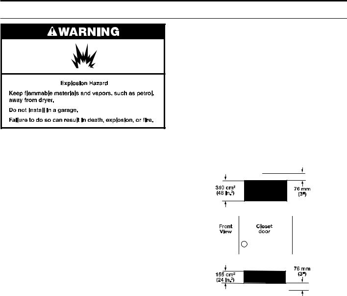
Recessed Area and Closet Installation Instructions
This dryer may be installed in a recessed area or closet. The dryer must not be installed behind a lockable door, a sliding door, or a door with a hinge on the opposite side to that of the dryer
in such a way that a full opening of the dryer door is restricted. For recessed area and closet installations, minimum clearances can be found on the warning label on the rear of the dryer or in “Dimensions/Clearances.”
The installation spacing is in millimeters and is the minimum allowable. Additional spacing should be considered for ease of installation, servicing, and compliance with local codes and ordinances.
If closet door is installed, the minimum unobstructed air opening in the top and bottom is required. Louvered doors with equivalent air openings are acceptable.
The dryer must be exhausted outdoors.
No other fuel-burning appliance may be installed in the same closet as the dryer.
NOTE: For installation in Australia and New Zealand, refer to AS/NZS 5601.1 for ventilation requirements.
NOTE: This dryer is not intended to be placed on top of a washer.
9
INSTALLATION REQUIREMENTS
Electrical Requirements
IMPORTANT: Observe all governing codes and ordinances.
You will need an earthed electrical outlet located within 610 mm (2 feet) of either side of the dryer.
This dryer is supplied/fitted with an electrical supply cord and plug. It should be connected to electrical supply socket at the voltage shown on the rating plate. The minimum supply fuse capacity should be 12 A. The dryer must be positioned
so that the plug is clearly visible and accessible. This plug also provides the function of an emergency stop control for the user. If the fitted plug is not used, the electrical connection must be carried out by a competent electrician in accordance with local or national codes.
If the supply cord is damaged, it must be replaced with a specially terminated cord by an authorized service agent or a similarly competent person in order to avoid a hazard.
Do not use an adapter.
Do not use an extension cord.
NOTE: In accordance with the European EMC Directive (2004/108/EC), the maximum electricity supply system impedance to which the gas dryer should be connected is declared to be 0.012 Ohm + j0.007 Ohm.
NOTE: Electrical safety standards: The manufacturer has chosen compliance with IEC/EN.60335 standards as the most appropriate for this product.
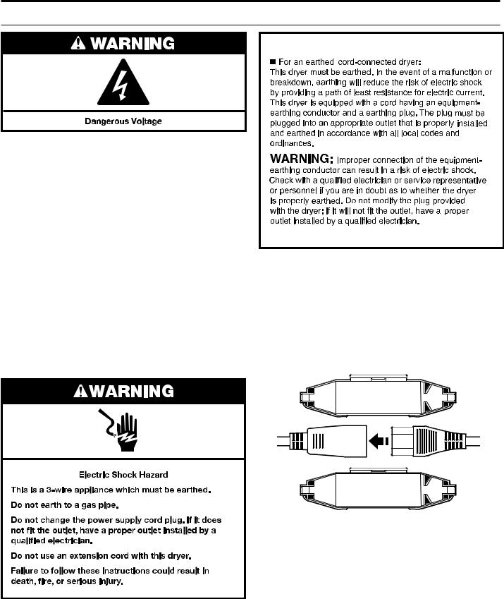
EARTHING INSTRUCTIONS
SAVE THESE INSTRUCTIONS
Using the universal cord included with this dryer:
The gas dryer is equipped with a universal cord with interchangeable plugs.
1.To use the universal cord, select the plug end that fits your electrical outlet, and plug it into the adapter on the supply cord.
2.Secure the plug end in place on the cord by aligning the two cover halves over the cord adapter and clipping them together.
If codes permit and an additional earth bond wire is used, it is recommended that a qualified electrician determine that the earth bond path is adequate.
10
INSTALLATION REQUIREMENTS
Gas Supply Requirements
IMPORTANT: Observe all governing codes and ordinances.
Gas Supply
Before installation, check that the local gas distribution conditions, nature of gas and pressure, and the adjustment of the appliance are compatible. Burner information will be
found on the model/serial rating plate in the door recess of the dryer. If this information does not agree with the type of gas available, see your dealer.
Natural Gas:
This dryer is factory adjusted for use with NATURAL GAS (G20), and no further adjustment should be required at installation.
L.P. Gas:
This dryer is also certified for use with L.P. (propane or butane) gases with appropriate conversion. No attempt shall be made to convert the appliance from the gas specified on the model/ serial rating plate for use with a different gas without consulting the serving gas supplier.
Conversion must be done by a competent service technician. Gas conversion kit (European Country), part number W10233219, is available for purchase from your dealer. Gas conversion kit (Australia), part number W10315369, is available for purchase from your dealer. Full instructions are supplied with the kit.
Natural Gas (France/Belgium):
This dryer is also certified for France/Belgium for use with G20/G25 gases (20 mbar/25 mbar) with appropriate conversion. No attempt should be made to convert this appliance from the gas specified on the gas rating label for use with a different gas without consulting the serving
gas supplier. Gas conversion must be done by a qualified gas service technician. Conversion kit, part number (W10181947), is available for purchase from your dealer. Full instructions are supplied with the kit.
Supply line requirements:
Provide a rigid gas supply line to the dryer location. It should be minimum 12.5 mm (1/2") ID. When acceptable to the gas supplier and local codes, 10 mm (3/8") ID rigid supply line may be used for lengths under 6.1 m (20'). Pipe-joint compounds resistant to the action of L.P. gas must be used.
NOTE: For installation in Australia and New Zealand, refer to AS/NZS 5601 for pipe sizing details.
Gas connection to the dryer itself should be made by means of a flexible gas hose suitable for the appliance and gas category in accordance with national installation regulations. If in doubt, contact the gas supplier. It should be minimum 10 mm (3/8") ID.
A means of restraint should be used between the dryer and the wall to avoid straining of the rigid gas supply when
the dryer is moved. An appropriate length of chain and a wall hook is recommended.
The dryer gas inlet connection is a 3/8" NPT thread.
An adapter is supplied for conversion to standard ISO.228-1 thread (3/8" BSP).
Check for leaks by using an approved noncorrosive leak-detection solution. Bubbles will show a leak. Correct any leak found. A pressure measurement tapping is provided on the gas valve within the dryer, accessible after removal of the lower front panel.
The dryer must be disconnected from the gas supply piping system during any pressure testing of that system.
11
VENTING REQUIREMENTS
WARNING: To reduce the risk of fire, this dryer MUST BE EXHAUSTED OUTDOORS.
IMPORTANT: Observe all governing codes and ordinances.
■■ Following these venting requirements will minimise ducting air noise.
■■ Exhaust air must not be discharged into a flue for exhausting fumes from appliances burning gas or other fuels, including open fires (i.e. available airflow into
the room should match airflow out from the room).
■■ Dryer exhaust must not be connected into any gas vent, chimney, wall, ceiling, attic, crawlspace, or a concealed space of a building. Only rigid or flexible metal vent shall be used for exhausting.
■■ Do not use an exhaust hood with a magnetic latch.
102 mm (4")
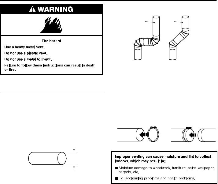
102 mm (4") heavy, metal exhaust vent
■■ Only a 102 mm (4") heavy, metal exhaust vent and clamps may be used.
■■ Do not use plastic or metal foil vent.
Rigid metal vent:
■■ Recommended for best drying performance and to avoid crushing and kinking.
Flexible metal vent: (Acceptable only if accessible to clean) ■■ Must be fully extended and supported in final dryer location.
■■ Remove excess to avoid sagging and kinking that may result in reduced airflow and poor performance.
■■ Do not install in enclosed walls, ceilings, or floors. ■■ The total length should not exceed 2.4 m (73⁄4 ft.).
■■ An exhaust hood should cap the vent to keep rodents and insects from entering the building.
NOTE: If using an existing vent system, clean lint from entire length of the system and make sure exhaust hood is not plugged with lint. Replace plastic or metal foil vents with
rigid metal or flexible metal vents. Review “Vent System Chart” and if necessary, modify existing vent system to achieve best drying performance.
Elbows:
■■ 45° elbows provide better airflow than 90° elbows.
Good |
Better |
■■ Plan installation to use the fewest number of elbows and turns.
■■ Allow as much room as possible when using elbows or making turns. Bend vent gradually to avoid kinking.
■■ Vent outlet is located at the center of the bottom dryer back.
■■ The vent can be routed up, down, left, right, behind the dryer, or straight out the back of the dryer.
Clamps:
■■ Use clamps to seal all joints.
■■ Exhaust vent must not be connected or secured with screws or other fastening devices that extend into interior of duct and catch lint. Do not use duct tape.
12
|
VENTING REQUIREMENTS |
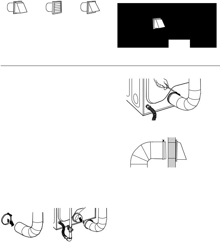
Vent Hoods |
|
|
|
102 mm (4") Diameter Exhaust Hoods |
Exhaust hood must be at least 305 mm (12") from the ground |
|
or any object that may be in the path of the exhaust (such as |
|
flowers, rocks, bushes, or snow). |
Box hood |
Louvered hood |
Angled hood |
30512"mmin.min.
 (305(12")mm)
Vent System Length
Maximum Vent Length/Vent Connection
Maximum length of vent system depends upon the type of vent used, number of elbows, and type of exhaust hood.
Vent System Chart (Rigid Metal Vent)
|
Box and |
|
No. of 90˚ Turns |
Louvered Hood |
Angled Hood |
|
|
|
0 |
39.6 m (130 ft.) |
39.3 m (129 ft.) |
|
|
|
1 |
38.1 m (125 ft.) |
36.3 m (119 ft.) |
|
|
|
2 |
35.1 m (115 ft.) |
33.2 m (109 ft.) |
|
|
|
3 |
32.3 m (106 ft.) |
30.5 m (100 ft.) |
|
|
|
4 |
29.9 m (98 ft.) |
28.0 m (92 ft.) |
|
|
|
For vent systems not covered by the “Vent Specification Chart,” see your parts distributor.
Provision must be made for enough air for combustion and ventilation. (Check governing codes and ordinances.) See “Recessed Area and Closet Installation Instructions” in the “Location” section.
A 102 mm (4") outlet hood is preferred. However, a 64 mm (21⁄2") outlet exhaust hood may be used. A 64 mm (21⁄2") outlet creates greater back pressure than other hood types. For permanent installation, a stationary vent system is required.
Connect Vent
1.If connecting to existing vent, make sure the vent is clean.
2.Using a 102 mm (4") clamp, connect vent to exhaust outlet in dryer.
3. Tighten hose clamp with Phillips screwdriver.
4.Make sure the vent is secured to exhaust hood with a 102 mm (4") clamp.
5.Move dryer into final position. Do not crush or kink vent. Make sure dryer is level.
Vent collar
NOTE: Do not remove vent collar.
13
VENTING REQUIREMENTS
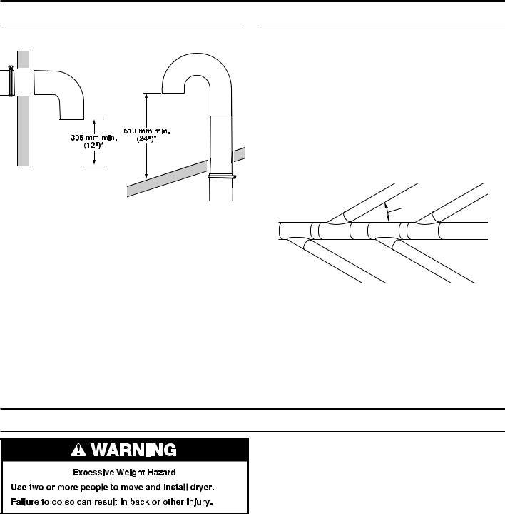
If an Exhaust Hood Cannot be Used
The outside end of main vent should have a sweep elbow directed downward.
*Minimum clearance above any accumulation of snow, ice, or debris such as leaves
If main vent travels vertically through the roof, rather than through wall, install a 180° sweep elbow on end of vent at least 610 mm (2 ft.) above surface of roof.
The opening in wall or roof shall have a diameter 13 mm (1⁄2") larger than vent diameter. Vent should be centered in opening.
Do not install screening over end of vent for best performance.
Multiple Dryer Venting
A main vent can be used for venting a group of dryers. The main vent should be sized to remove 5663 l/min. (200 CFM) of air per dryer. Large-capacity lint screens of proper design may be used in main vent if checked and cleaned frequently. The room where the dryers are located should have make-up air equal to or greater than CFM of all the dryers in the room.
Back-draft Damper Kit, Part No. 3391910, is available from your distributor and should be installed in the vent of each dryer to keep exhausted air from returning into dryers and to keep exhaust in balance within main vent. Unobstructed return air openings are required.
Each vent should enter the main vent at an angle pointing in the direction of the airflow. Vents entering from the opposite side should be staggered to reduce the exhausted air from interfering with the other vents.
 Air ow
The maximum angle of each vent entering the main vent should be no more than 30°.
Keep air openings free of dry cleaning fluid fumes. Fumes create acids which, when drawn through the dryer heating units, can damage dryers and items being dried.
A clean-out cover should be located on the main vent for periodic cleaning of the vent system.
GAS SUPPLY REQUIREMENTS
Make Gas Connection
3. Open the shut-off valve in the gas supply line.
4. Test all connections by brushing on an approved noncorrosive leak-detection solution. Bubbles will show a leak. Correct any leaks found.
1.Remove red cap from gas pipe.
2.Connect gas supply to dryer. If the flexible gas hose has
10 mm (3/8") BSP thread, use the supplied conversion thread adapter. Use pipe-joint compound resistant to the action
of L.P. gas for gas connections.
If necessary for service, open the toe panel. Use a putty knife to press on the two toe panel locks located at the top of the toe panel. Pull downward on the toe panel to open. Toe panel is hinged at the bottom.
14

INSTALLING LEVELING LEGS
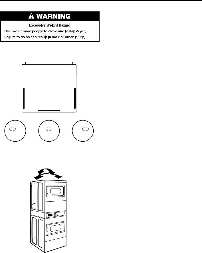
1. Prepare dryer for leveling legs
NOTE: Slide dryer onto cardboard or hardboard before moving to avoid damaging floor covering.
Using two or more people, move dryer to desired installation location.
Take tape off front corners of dryer. Open dryer and remove
the literature and parts packages. Wipe drum interior with damp cloth to remove any dust.
Take two cardboard corners from the dryer carton and place them on the floor in back of the dryer. Firmly grasp body of the dryer and gently lay it on its back on the cardboard corners.
2. Screw in leveling legs
Examine leveling legs and find diamond marking. Screw legs into leg holes by hand. Use an adjustable wrench or
25 mm (1") hex-head socket wrench to finish turning legs until diamond marking is no longer visible. Then fit a covered foot boot over each leg foot.
Diamond marking
Foot

To protect the floor, use a large piece of cardboard from the dryer carton. Stand dryer up on the cardboard. Slide the dryer until it is close to its final location. Leave enough room for electrical connection and to connect the exhaust vent.
15
LEVELING
Leveling your dryer properly reduces excess noise and vibration.
1.Remove cardboard from beneath dryer. Place a level on top edges of dryer, checking each side and front. If not level, tip dryer and adjust legs up or down, repeating as necessary.
3.If dryer is not level, turn the leveling legs counterclockwise to lower the dryer or clockwise to raise the dryer. Recheck levelness of dryer and that all four legs are firmly in contact with the floor. Repeat as needed.
HELPFUL TIP: You may want to prop up front of dryer about 102 mm (4") with a wood block or similar object that will support weight of dryer.
|
|
|
|
|
|
|
|
|
|
|
|
|
|
|
|
|
|
|
|
|
|
|
|
|
|
|
|
|
|
|
|
|
|
|
|
|
|
|
|
|
|
|
|
|
|
|
|
|
|
|
|
Not Level |
|
|
|
LEVEL |
|
|
|
Not Level |
|
||||||
2.Grip dryer from top and rock back and forth, making sure all four legs are firmly on floor. Repeat, rocking dryer from side to side. If dryer rocks, adjust leveling legs.
16

COMPLETE INSTALLATION
1.Check the electrical requirements. Be sure that you have the correct electrical supply and the recommended earthing method. See “Electrical Requirements.”
2.Check that all parts are now installed. If there is an extra part, go back through the steps.
3.Check that you have all of your tools.
4.Dispose of/recycle all packaging materials.
 WARNING
Electric Shock Hazard This dryer must be earthed.
Securely tighten all electrical connections.
Failure to do so can result in death, fire, or electric shock.
5. Connect power.
6.Check dryer operation. Using a full heat cycle, let the dryer run for at least 5 minutes. Dryer will stop when time is used up.
NOTE: Dryer door must be closed for dryer to operate. When door is open, dryer stops, but timer continues to run. To restart dryer, close door and press cycle button.
7.If the burner does not ignite and you can feel no heat inside the dryer, shut off dryer for five minutes. Check that all supply valve controls are in On position and that the electrical cord is plugged in. Repeat 5-minute test.
17
REVERSING DOOR SWING (OPTIONAL)
You can change your door swing from a right-side opening to left-side opening, if desired.
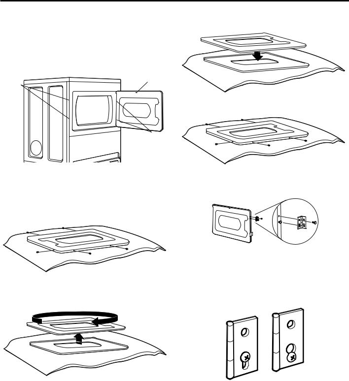
Remove the Door Assembly
1.Place a towel or soft cloth on top of work space to avoid scratching of the surface.
2.Open dryer door. Remove button screws from cabinet side of hinges. Loosen (do not remove) top screws from cabinet side of hinges.
Door catch
Plugs
Hinges
7.Be certain to keep cardboard spacer centered between doors. Reattach outer door panel to inner door panel so handle is on the side where hinges were just removed.
8. Reattach screws at top, bottom, and side of door (five screws).
3.Lift door until top screws in cabinet are in large part of hinge slot. Pull forward off screws. Set door (handle side up) on top of towel. Remove top screws from cabinet.
4.Remove screws attaching hinges to door.
5.Remove screws at top, bottom, and side of door (five screws).
6.Holding door over towel, grasp sides of outer door and gently lift to separate it from inner door. Do not use a putty knife to pry apart. Do not pull on door seal or plastic door catch.
9.Attach door hinges to dryer door so that larger hole is at the bottom of the hinge and the hinge pin is toward the door front.
10.Remove the four screws that attach two plugs on the left side. Attach plugs to right side using the same four screws.
11.Insert screws into bottom holes on left side of cabinet. Tighten screws halfway. Position door so large end of door hinge slot is over screws. Slide door up so screws are in bottom of slots. Tighten screws. Insert and tighten top screws in hinges.
12.Close door and check that door strike aligns with door catch. If needed, slide door catch left or right within slot to adjust alignment.
18

MAINTENANCE INSTRUCTIONS
■■ Clean lint screen before and after each cycle. ■■ Removing accumulated lint:
From inside the dryer cabinet:
Lint should be removed every 2 years or more often, depending on dryer usage. Cleaning should be done by a qualified person.
From the exhaust vent:
Lint should be removed every 2 years, or more often, depending on dryer usage.
■■ Keep area around dryer clear and free from combustible materials, gasoline, and other flammable vapors and liquids.
■■ Keep dryer area clear and free from items that would obstruct the flow of combustion and ventilation air.
If dryer does not operate, check the following:
■■ Electrical supply is connected.
■■ Circuit breaker is not tripped or house fuse is not blown.
■■ Door is closed. Listen closely to hear the door switch activate.
■■ Cycle selection button has been pushed firmly and display shows cycle time.
■■ Check that gas supply shut-off valves are set in open position.
IF YOU NEED ASSISTANCE
If you need help, contact the dealer from whom you purchased the appliance, or a Maytag designated service company.
When calling, please know the purchase date and the complete model and serial number of your appliance. This information will help us to better respond to your request.
19
TECHNICAL SPECIFICATIONS – GAS DRYER
220-240 V~50Hz 1ph 3 A max. IPX4 Clothes capacity: 9.0 kg max. Sound pressure level, LpA: 58 dBA (uncertainty, Kpa: +/-10 dBA) Total mass: 135 kg max.
Factory set for NATURAL GAS: Injector size: 2.2 mm Heat input gross: 5.9 kW
European Country: |
CH, CZ, CY, ES, GB, GR, |
BG, CY, CZ, DK, EE, FI, GR, |
|
IE, IT, LT, PT, SI, SK, TR |
HR, IT, LT, NO, RO, SE, SI, SK |
||
|
|||
|
|
|
|
European Gas Category: |
II2H3+ |
II2H3B/P |
|
Gas Flow Rate: |
0.562703 m3/hr |
0.562703 m3/hr |
|
Supply Pressure (G20): |
20 mbar |
20 mbar |
|
|
|
|
|
Factory Adjusted Pressure: |
7.4 mbar |
7.4 mbar |
|
|
|
|
|
With L.P. Gas Conversion Kit: Injector size: 1.25 mm Heat input gross: 6.4 kW |
|
||
|
|
|
|
European Country: |
CH, CZ, CY, ES, GB, GR, |
BG, CY, CZ, DK, EE, FI, GR, |
|
IE, IT, LT, PT, SI, SK, TR |
HR, IT, LT, NO, RO, SE, SI, SK |
||
|
|||
|
|
|
|
European Gas Category: |
II2H3+ |
II2H3B/P |
|
Butane Supply Pressure (G30): |
28-30 mbar |
30 mbar |
|
|
|
|
|
Adjusted Pressure: |
N/A |
N/A |
|
|
|
|
|
L.P. Supply Pressure (G31): |
37 mbar |
30 mbar |
|
|
|
|
|
Adjusted Pressure: |
N/A |
N/A |
|
|
|
|
|
With France/Belgium NATURAL GAS conversion kit: Injector size 1.65 mm Heat input gross: 5.9 kW
European Country: |
|
FR, BE |
|
|
|
|
|
European Gas Category: |
|
I2E+ |
|
Supply Pressure (G20): |
|
20 mbar |
|
|
|
|
|
Supply Pressure (G25): |
|
25 mbar |
|
|
|
|
|
Adjusted Pressure: |
|
N/A |
|
|
|
|
|
Factory set for NATURAL GAS: Injector size: 2.2 mm Heat input gross: 5.9 kW |
|
||
|
|
||
Country: |
AT, BG, CH, CZ, DK, EE, ES, FI, GB, GR, HR, |
||
IE, IS, IT, LT, LV, NO, PT, RO, SE, SI, SK, TR |
|||
|
|||
|
|
|
|
European Gas Category: |
|
I2H |
|
Gas Flow Rate: |
|
0.562703 m3/hr |
|
Supply Pressure (G20): |
|
20 mbar |
|
|
|
|
|
Factory Adjusted Pressure (G20): |
|
7.4 mbar |
|
|
|
|
|
Factory set for NATURAL GAS: Injector size: 2.2 mm Heat input gross: 5.9 kW |
|
||
|
|
|
|
Country: |
|
LU, RO |
|
|
|
|
|
European Gas Category: |
|
II2E3B/P |
|
Gas Flow Rate: |
|
0.562703 m3/hr |
|
Supply Pressure (G20): |
|
20 mbar |
|
|
|
|
|
Factory Adjusted Pressure (G20): |
|
7.4 mbar |
|
|
|
|
|
With L.P. Gas Conversion Kit: Injector size: 1.25 mm Heat input gross: 6.4 kW |
|
||
|
|
|
|
Country: |
|
LU, RO |
|
|
|
|
|
European Gas Category: |
|
II2E3B/P |
|
Butane Supply Pressure (G30): |
|
30 mbar |
|
|
|
|
|
Adjusted Pressure: |
|
N/A |
|
|
|
|
|
L.P. Supply Pressure (G31): |
|
30 mbar |
|
|
|
|
|
Adjusted Pressure: |
|
N/A |
|
|
|
|
|
20
|
|
TECHNICAL SPECIFICATIONS – GAS DRYER |
|||
|
|
|
|
|
|
|
Factory set for NATURAL GAS: Injector size: 2.2 mm Heat input gross: 5.9 kW |
|
|
||
|
|
|
|
|
|
|
Country: |
DE, LU, PL, RO |
|
|
|
|
|
|
|
|
|
|
European Gas Category: |
I2E |
|
|
|
|
Gas Flow Rate: |
0.562703 m3/hr |
|
|
|
|
Supply Pressure (G20): |
20 mbar |
|
|
|
|
|
|
|
|
|
|
Factory Adjusted Pressure (G20): |
7.4 mbar |
|
|
|
|
|
|
|
|
|
|
Factory set for Australia/New Zealand NATURAL GAS: Injector size: 2.2 mm Heat input gross: 5.9 kW |
|
|
||
|
|
|
|
|
|
|
Country: |
AU, NZ |
|
|
|
|
|
|
|
|
|
|
Supply Pressure (G20): |
minimum 1.13 kPa |
|
|
|
|
|
|
|
|
|
|
Adjusted Pressure (Test Point Pressure): |
0.74 kPa |
|
|
|
|
|
|
|
|
|
|
Nominal Hourly Gas Consumption: |
21.1 MJ/h |
|
|
|
|
|
|
|
|
|
|
With Australia L.P. Gas Conversion Kit: Injector Size: 1.40 mm Heat input gross: 6.54 kW |
|
|
||
|
|
|
|
|
|
|
Country: |
AU, NZ |
|
|
|
|
|
|
|
|
|
|
L.P. Supply Pressure: |
2.75 kPa |
|
|
|
|
|
|
|
|
|
|
Adjusted Pressure: |
2.75 kPa |
|
|
|
|
|
|
|
|
|
|
Nominal Hourly Gas Consumption: |
23 MJ/h |
|
|
|
|
|
|
|
|
|
|
Factory set for NATURAL GAS: Injector size: 2.2 mm Heat input gross: 5.0 kW |
|
|
||
|
|
|
|
|
|
|
Country: |
NL |
|
|
|
|
|
|
|
|
|
|
European Gas Category: |
I2L |
|
II2L3B/P |
|
|
Gas Flow Rate: |
0.562703 m3/hr |
|
0.562703 m3/hr |
|
|
Gas Flow Rate: |
25 mbar |
|
25 mbar |
|
|
|
|
|
|
|
|
Factory Adjusted Pressure (G25) : |
7.4 mbar |
|
7.4 mbar |
|
|
|
|
|
|
|
|
With L.P. Gas Conversion Kit: Injector size: 1.25 mm Heal input gross: 6.4 kW |
|
|
||
|
|
|
|
|
|
|
Country: |
MT, PL |
|
NL |
|
|
|
|
|
|
|
|
European Gas Category |
I3B/P |
|
II2L3B/P |
|
|
Butane Supply Pressure (G30) |
30 mbar |
|
|
|
|
|
|
|
|
|
|
Adjusted Pressure: |
N/A |
|
|
|
|
|
|
|
|
|
|
L.P. Supply Pressure: |
30 mbar |
|
|
|
|
|
|
|
|
|
|
Adjusted Pressure: |
N/A |
|
|
|
|
|
|
|
|
|
NOTE: Conversion kit: From Natural Gas to L.P. Gas - Europe: Whirlpool Part No. W10233219. Conversion kit: From Natural Gas to L.P. Gas - Australia: Whirlpool Part No. W10315369. Conversion kit: From Natural Gas to Natural Gas - France/Belgium: Whirlpool Part No. W10181947.
Manufacturer: Whirlpool Corporation, Benton Harbor, Michigan 49022, U.S.A.
Manufacturing Site: Whirlpool Corporation, 1300 Marion-Agosta Rd., Marion, OH, 43302, U.S.A. EU Representatives: Whirlpool EMEA S.p.A., Via Carlo Pisacane, 1, 20016 Pero (MI) Italy
21
ELECTRONIC CONTROL SETUP INSTRUCTIONS
IMPORTANT
Electrostatic Discharge (ESD)
Sensitive Electronics
ESD problems are present everywhere. ESD may damage or weaken the electronic control assembly. The new control assembly may appear to work well after repair is finished, but failure may occur at a later date due to ESD stress.
nUse an anti-static wrist strap. Connect wrist strap to green earth connection point or unpainted metal in the appliance.
-OR-
Touch your finger repeatedly to a green earth connection point or unpainted metal in the appliance.
nBefore removing the part from its package, touch the anti-static bag to a green ground connection point or unpainted metal in the appliance.
nAvoid touching electronic parts or terminal contacts; handle electronic control assembly by edges only.
nWhen repackaging failed electronic control assembly in anti-static bag, observe above instructions.
General User Information
“OUT OF ORDER” SHOWING IN DISPLAY – This condition indicates the dryer is inoperative. Diagnostic or failure code will follow the scrolling message.
“0 MINUTES” SHOWING IN DISPLAY – This indicates the cycle is complete and the dryer cannot be operated. Coins dropped or debit inputs during this condition will be stored in escrow but cannot be used until normal operation is restored by opening and closing the door. If a door switch has failed, it must be replaced before normal operation can be restored.
COLD START (Initial first use) – Dryer is programmed at the factory as follows:
45 minutes dry time for PN models; 5 minutes per coin for PD models.
$1.50 dry price (fixed cycle with top off – PD Models) $0.00 dry price (fixed cycle – PN Models)
WARM START (after power failure) – A few seconds after power is restored, if a cycle was in progress at the time of the power failure, “RESELECT CYCLE” will flash in the display. This indicates a fabric setting button needs to be pressed
to restart dryer.
PRICING – After the door is opened and then closed following the completion of a cycle, the display indicates the cycle price (unless set for free operation). As coins are dropped or debit inputs arrive, the display will change to lead the user through the initiation of a cycle.
There are four (4) types of dryer pricing:
Fixed “Vend” Pricing
A dryer set up for “Fixed Cycle” operation can only accept additional time accumulated by increments equal to the length of a complete dry cycle. A maximum number of minutes may be purchased; no additional credit is given when the maximum minutes are displayed.
Accumulator Pricing
If the price is set to one coin 1, then accumulator pricing
is in effect. Cycle time can be purchased one coin at a time (PD models) up to the maximum time.
Fixed Cycle With Top Off Pricing
A dryer set to offer “Top Off” capability will allow time to be added to an existing dry cycle in increments equal to the number of minutes of dry time per coin (coin 1), up to the maximum minutes, regardless of the cost required to start the dryer. No credit is given for coins or debit inputs entered when the control is displaying the maximum minutes.
PN Models set up as PR: In Enhanced Debit Mode, the top off price can be set independently (see VALUE OF COIN 2), and the top off time is calculated according to the following
equation: |
|
|
|
|
|
top off price |
= |
top off time |
|
|
full cycle price |
full cycle length |
||
|
|
|||
Hundredth increment offset is not applied to top off purchases.
PN Models – The factory has preset the cycle price to zero. When this happens, “SELECT CYCLE” will appear rather than a cycle price. Any cycle started as a free cycle will automatically terminate when the door is opened.
DEBIT CARD READY – This dryer has a control that is debit card ready, but the dryer is not.
Display
After the dryer has been installed and plugged in, the display will show “0 minutes.”
PD Models
PRICE |
UPPER DRYER |
||||
1.50 |
|
|
|
|
|
WHITES |
|
PERMANENT |
|
DELICATES |
|
& COLORS |
|
PRESS |
|
||
|
|
|
|||
HIGH HEAT |
|
MEDIUM HEAT |
|
LOW HEAT |
|
PRICE |
|
|
|
|
|
WHITES |
|
PERMANENT |
|
DELICATES |
|
1.50 |
& COLORS |
|
PRESS |
|
|
|
|
|
|||
HIGH HEAT |
|
MEDIUM HEAT |
|
LOW HEAT |
|
LOWER DRYER
Once the dryer has been plugged in and the dryer door opened and closed, the display will show the vent price. PN models are factory preset for free cycles; the display will flash “SELECT CYCLE.”
PN Models
SELECT CYCLE |
UPPER DRYER |
||||
|
|||||
|
|
|
|
|
|
|
WHITES |
|
PERMANENT |
|
DELICATES |
|
& COLORS |
|
PRESS |
|
|
|
|
|
|
||
|
HIGH HEAT |
|
MEDIUM HEAT |
|
LOW HEAT |
SELECT CYCLE |
|
|
|
|
|
WHITES |
|
PERMANENT |
|
DELICATES |
|
|
& COLORS |
|
PRESS |
|
|
|
|
|
|
||
|
HIGH HEAT |
|
MEDIUM HEAT |
|
LOW HEAT |
LOWER DRYER
Control Set-up Procedures
IMPORTANT: Read all instructions before operating.
The fabric setting buttons along with the digital display
are used to set up the dryer controls. The display can contain 4 numbers and/or letters and a decimal point. These are used to indicate the set-up codes and related code values available for use in programming the dryer.
How to Use the Buttons to Program the Controls
1.The WHITES AND COLORS button is used to adjust the values associated with set-up codes. Pressing the button will change the value by increments. Rapid adjustment is possible by holding down the button.
2.The PERM. PRESS button will advance the display through the set-up codes. Pressing the button will advance the display to the next available set-up code. Holding down
the PERM. PRESS button will automatically advance through the set-up codes at a rate faster than 1 per second.
3.The DELICATES button is used to select or deselect options.
22

ELECTRONIC CONTROL SETUP INSTRUCTIONS
Start Operating Set-up
■■ PD Models: Insert service door key, turn, and lift to remove service door.
■■ PN Models: Remove the AA1 jumper from the control board (see procedure below) or use the Service Access Code below. Once the debit card reader is installed (according
to the reader manufacturer’s instructions), the set-up mode can be entered by inserting a manual set-up card (supplied by the reader manufacturer) into the card slot. If manual set-up card is not available, manual set-up mode cannot be entered. However, diagnostic mode can be entered
by removing connector AA1 on the circuit board.
IMPORTANT: The console must not be opened unless power is first removed from the dryer. To access connector AA1:
gUnplug dryer or disconnect power.
gOpen console, disconnect plug on AA1, close console.
gPlug in dryer or reconnect power.
nPN Models Equipped with Programming Switch: Insert access panel key and turn counterclockwise.
nPN Models with Gen. 2 Debit Card Reader:
Once a Gen. 2 debit card reader is installed (according to the reader manufacturer’s instructions), the set-up mode can only be entered by inserting a manual set-up card (supplied by the reader manufacturer) into the card slot. If manual set-up card is not available, only diagnostic mode can be entered.
nAlternate method of entering Set-up Mode by entering Service Access Code: This code can be entered to access set-up mode without removing the console on dryers just removed from the carton, or not yet programmed. The Service Access Code only functions on dryers set up for
0vend price without any Special Pricing setup, and the Coin/Debit Option must be set to “J._d”. If the dryer is not in failure mode, the door must be opened to proceed. Using only the three bottom buttons (numbered 1, 2, and
3from left to right):
1.Press 2 for longer than 2 seconds but less than 10 seconds.
2.Press 1 and 3 simultaneously for 2 seconds. Display shows S 3.
3.Press 1 and 2 simultaneously. Display shows S 4.
4.Press 2 and 3 simultaneously. Display shows S 5.
5.Press 2.
6.Wait at least 2 seconds, but not more than 15 seconds; then press in succession: 3, 2, 1, 3.
The dryer is now in the set-up mode.
NOTE: This dryer is preset at the factory and does not require any programming. However, if you want to change the settings, follow the “Set-Up Codes” guide below. PD models require a payment system or OPL kit to be installed prior to operation.
nPD units are pre-set at the factory for fixed cycle price with top off.
nPN units are pre-set for fixed cycle operation so they can be run without payment.
Set-Up Codes
■■ The PERM. PRESS button will advance you from code to code.
■■ The WHITE AND COLORS button will change the code value.
■■ The DELICATES button will select or deselect options.
PN MODELS: The set-up codes are the same as for the PD models except where noted.
The set-up code is indicated by the one or two left-hand characters. The set-up code value is indicated by the two or three right-hand characters.
NOTE: The first line of each code indicates the factory default.
Code Explanation
6 06 REGULAR CYCLE PRICE
6 06 Represents the number of quarters (coin 1) needed to start the dryer; may adjust from 0–39. (See b.xx set up for VALUE OF COIN 1.) Advance from 0–39 by pressing the WHITES AND COLORS button. Factory default of 6 x coin 1.
6 00 PN MODELS ONLY: Factory default of 6 00, or 0 coins.
•Press the PERM. PRESS button once to advance to next code.
7 05 REGULAR DRY TIME
7 05 PD MODELS: Represents the number of minutes per coin (coin 1).
Factory default of 5 minutes per coin. Example: 6 coins x 5 minutes = 30 minutes.
By pressing the WHITES AND COLORS button, value adjusts from 1 to the maximum minutes.
7 45 PN MODELS: Represents the cycle length for free cycles. Example: “7 45” = 45 minutes.
•Press the PERM. PRESS button once to advance to next code.
8 00 TYPE OF DRYER PRICING
8 00 Fixed Cycle with Top Off. For detailed description, see “General User Information.”
8 FC PN MODELS ONLY: Factory default of FC. Fixed Cycle. For detailed description, see “General User Information.” Use the DELICATES button to change this selection.
•Press the PERM. PRESS button once to advance to next code.
9 00 CYCLE COUNTER OPTION
This option is either NOT SELECTED “OFF” or SELECTED “ON.”
9 00 Not Selected “OFF.”
9 0C Selected “ON” and not able to be deselected.
•Press the DELICATES button 3 consecutive times to select “ON.” Once selected “ON,” it cannot be deselected.
•Press the PERM. PRESS button once to advance to next code.
If cycle counter (9 0C) is selected, the following is true:
1 00 |
Cycles in HUNDREDS |
1 02 |
= 200 |
2 00 |
Cycles in ONES |
2 25 |
= 25 |
|
|
|
|
TOTAL CYCLES = 225
This is “VIEW ONLY” and cannot be cleared.
•Press the PERM. PRESS button once to advance to next code.
23

ELECTRONIC CONTROL SETUP INSTRUCTIONS
Code Explanation
1. 00 MONEY COUNTER OPTION
This option is either NOT SELECTED “OFF” or SELECTED “ON.”
1. 00 Not Selected “OFF.”
1.0C Selected “ON.”
•Press the DELICATES button 3 consecutive times to select “ON” and 3 consecutive times
to deselect (Not Selected “OFF”). Counter resets by going from “OFF” to “ON.”
1.C0 Selected “ON” and not able to be deselected.
•To select “ON” and not able to be deselected, first select “ON”; then within 2 seconds, press the DELICATES button twice, the WHITES AND COLORS button once, and exit set-up mode.
•Press the PERM. PRESS button once to advance to next code.
2.00 SPECIAL PRICING OPTIONS
This option is either NOT SELECTED “OFF” or SELECTED “ON.”
2. |
00 |
Not Selected “OFF.” |
2. |
SP |
Selected “ON.” |
|
|
• Press the DELICATES button once to change |
|
|
this selection. |
If SPECIAL PRICING OPTION is selected, there is access to codes “3.XX” through “9.XX.”
•Press the PERM. PRESS button once to advance to next code.
If money counter (1.0C or 1.C0) is selected, the following is true:
3 00 |
Currency amount |
3 01 |
= 100.00 |
|
|
in HUNDREDS |
|
|
|
4 00 |
Currency amount |
4 68 |
= |
68.00 |
|
in ONES |
|
|
|
5 00 |
Currency amount |
5 75 |
= |
00.75 |
|
in HUNDREDTHS |
|
|
|
|
|
|
|
|
TOTAL = 168.75
OPTIONS 3.XX – 9.XX TO USE IF SPECIAL PRICING IS SELECTED
Code Explanation
3. 06 SPECIAL CYCLE PRICE
3.06 Represents the number of coins (coin 1) to start the dryer; may adjust from 0–39. (See b.xx set up for VALUE OF COIN 1.)
•Advance from 0–39 by pressing the WHITES AND COLORS button. Factory default of 6 x coin 1.
3.00 PN MODELS ONLY: Factory default of 0 coins.
•Press the PERM. PRESS button once to advance to next code.
4. 05 SPECIAL DRY TIME
4.05 PD MODELS: Represents the number of minutes per coin (coin 1).
•Factory default of 5 minutes per coin. Example: 6 coins x 5 minutes = 30 minutes.
•By pressing the WHITES AND COLORS button, the value can be adjusted from 1 to the maximum minutes.
4.45 PN MODELS: Represents the cycle length for free cycles. Example: “4 45” = 45 minutes.
•Press the PERM. PRESS button once to advance to next code.
5.00 TIME-OF-DAY CLOCK, MINUTES
5.00 This is the TIME-OF-DAY CLOCK, minute setting; select 0–59 minutes by pressing the WHITES AND COLORS button.
•Press the PERM. PRESS button once to advance to next code.
6.00 TIME-OF-DAY CLOCK, HOURS
NOTE: Uses military time or 24 hr. clock.
6.00 This is the TIME-OF-DAY CLOCK, hour setting; select 0–23 hours by pressing the WHITES AND COLORS button.
•Press the PERM. PRESS button once to advance to next code.
24

ELECTRONIC CONTROL SETUP INSTRUCTIONS
OPTIONS 3.XX – 9.XX TO USE IF SPECIAL PRICING IS SELECTED (CONT.)
Code Explanation
7. 00 SPECIAL PRICE START HOUR
NOTE: Uses military time or 24 hr. clock.
7.00 This is the start hour, 0–23 hours.
•Select START HOUR by pressing the WHITES AND COLORS button.
•Press the PERM. PRESS button once to advance to next code.
8.00 SPECIAL PRICE STOP HOUR
NOTE: Uses military time or 24 hr. clock.
8.00 This is the stop hour, 0–23 hours.
•Select STOP HOUR by pressing the WHITES AND COLORS button.
•Press the PERM. PRESS button once to advance to next code.
9.10 SPECIAL PRICE DAY
9.10 This represents the day of the week and whether special pricing is selected for that day. A number followed by “0” indicates no selection that particular day (9. 10). A number followed by an “S” indicates selected for that day (9. 1S).
Days of the week (1–7) are selected by pressing the WHITES AND COLORS button. Press the DELICATES button once to select special pricing for each day chosen.
When exiting set-up code “9.,” the display must show the current day of week:
DISPLAY |
DAY OF WEEK |
CODE (selected) |
|
|
|
|
|
10 |
Day 1 = Sunday |
1S |
|
20 |
Day 2 = Monday |
2S |
|
30 |
Day 3 = Tuesday |
3S |
|
40 |
Day 4 |
= Wednesday |
4S |
50 |
Day 5 |
= Thursday |
5S |
60 |
Day 6 |
= Friday |
6S |
70 |
Day 7 |
= Saturday |
7S |
•Press the PERM. PRESS button once to advance to next code.
A.00 VAULT VIEWING OPTION
This option is either NOT SELECTED “OFF” or SELECTED “ON.”
A. 00 |
Not Selected “OFF.” |
A. SC |
Selected “ON.” |
|
• Press the DELICATES button once to change |
|
this selection. When selected, the money and/or |
|
cycle counts will be viewable (if counter option(s) |
|
is selected) when the coin box is removed. |
|
• Press the PERM. PRESS button once to advance |
|
to next code. |
Code Explanation
b. 05 VALUE OF COIN 1
b.05 This represents the value of coin 1 in the quantity of 5% increments of the larger coin value.
5 x 5% = 25%.
•By pressing the WHITES AND COLORS button, there is an option of 1–199 for the quantity
of 5% increments. With coin slide activation, this represents the total vend price.
•Press the PERM. PRESS button once to advance to next code.
C. 20 VALUE OF COIN 2
C.20 This represents the value of coin 2 in the quantity of 5% increments of the larger coin value.
20 x 5% = 100%.
By pressing the WHITES AND COLORS button, there is the option of 1–199 for the quantity of 5% increments.
C.05 PN MODELS: This represents the value of coin 2 in the quantity of 5% increments of the larger coin value. Factory default = 5 x 5% of the larger coin value.
PN MODELS USING ENHANCED DEBIT:
This represents the value of top off in quantity
of 5% increments of the larger coin value. Factory default = 5 x 5% of the larger coin value.
•Press the PERM. PRESS button once to advance to next code.
d.00 COIN SLIDE OPTION
This option is either NOT SELECTED “OFF”
or SELECTED “ON.” Replacement of metercase will be needed for coin slide mounting.
d. 00 |
Not Selected “OFF.” |
d. CS |
Selected “ON.” |
|
NOTE: This option needs to be set to “00” unless |
|
the metercase has been changed to accept a coin |
|
slide device. |
|
• Press the DELICATES button 3 consecutive |
|
times for this selection. When coin slide mode is |
|
selected, set “b.” equal to value of slide in coins. |
|
Set “6 xx” (REGULAR CYCLE PRICE) and “3.xx” |
|
(SPECIAL CYCLE PRICE) to number of slide |
|
operations. 6 01 and 3. 01 = 1 slide push. |
|
NOTE: If the installer sets up “CS” on a coin drop |
|
model, it will not register coins. |
•Press the PERM. PRESS button once to advance to next code.
E.00 ADD COINS OPTION
This option is either NOT SELECTED “OFF” or SELECTED “ON.” This option causes the customer display to show the number of coins (coin 1) to enter, rather than the amount.
E. 00 |
Not Selected “OFF.” |
E. AC |
Selected “ON.” |
|
• Press the DELICATES button 3 consecutive times |
|
to change this selection. |
|
PN MODELS: This option is not selectable. |
|
• Press the PERM. PRESS button once to advance |
|
to next code. |
25

ELECTRONIC CONTROL SETUP INSTRUCTIONS
Code |
Explanation |
|
|
J. Cd |
PAYMENT MODE (COIN/DEBIT OPTION) |
|
|
J. Cd |
Both coin and debit selected. (NOT AVAILABLE) |
J. C_ |
Coins selected, debit disabled. Press the |
|
DELICATES button 3 consecutive times to change |
|
this selection. |
J._d |
PN models: Factory default to J._d. Debit Card |
|
selected, coins disabled. Press the DELICATES |
|
button 3 consecutive times to change this |
|
selection. |
J. Ed |
Enhanced Debit is self-selected when a Generation |
|
2 card reader is installed in the dryer. The Ed option |
|
cannot be manually selected or deselected. |
|
(NOT AVAILABLE) |
•Press the PERM. PRESS button once to advance to next code.
L.00 PRICE SUPPRESSION OPTION
This option is either NOT SELECTED “OFF” OR SELECTED “ON.” This option causes the customer display to show “ADD” or “AVAILABLE” rather than the amount of money to add. (Used mainly in debit installations.)
L. 00 |
Not Selected “OFF.” |
L. PS |
Selected “ON.” |
•Press the DELICATES button once to change this selection.
•Press the PERM. PRESS button once to advance to next code.
n.CE CLEAR ESCROW OPTION
This option is either NOT SELECTED “OFF” OR SELECTED “ON.” When selected, money held in escrow for 30 minutes without further escrow or cycle activity will be cleared.
n. 00 |
Not Selected “OFF.” |
n. CE |
Selected “ON.” |
|
• Press the DELICATES button once to change this |
|
selection. |
|
• Press the PERM. PRESS button once to advance |
|
to next code. |
|
|
Code Explanation
U. 00 COIN INCREMENT OFFSET
U.00 This represents the hundredth increment price offset used in Generation 2 (Enhanced Debit) PN models. Choose from 0–4 hundredths by pressing the WHITES AND COLORS button. (NOT AVAILABLE)
•Press the PERM. PRESS button once to advance to next code.
END of SET-UP PROCEDURES.
EXIT FROM SET-UP MODE
nPD MODELS: Reinstall access door.
nPN Models where AA1 plug was removed:
1.Unplug dryer or disconnect power.
2.Open console, reinsert jumper into AA1, and close console.
3.Plug in dryer or reconnect power.
nPN WITH PROGRAMMING SWITCH: Turn key clockwise and remove.
nIf Service Access Code was used to enter set-up mode: From Set-up Code 8, press button #1 for 4 seconds, wait 2 minutes without touching any buttons (without diagnostic modes running), or power down the dryer; then reapply power.
26

MAYTAG COMMERCIAL LAUNDRY
LIMITED WARRANTY
IF YOU NEED SERVICE:
Contact your authorized Maytag Commercial Laundry distributor. To locate your authorized Maytag Commercial Laundry distributor, visit www.maytagcommerciallaundry.com.
For written correspondence:
Maytag Commercial Laundry Service Department
2000 N M 63
Benton Harbor, Michigan 49022-2632 USA
|
FIVE YEAR LIMITED WARRANTY |
WHAT IS COVERED |
WHAT IS NOT COVERED |
FIVE YEAR LIMITED WARRANTY |
1. All other costs including labor, transportation, shipping, or custom duties for |
(PARTS ONLY — LABOR NOT INCLUDED) |
covered parts. |
For the first five years from the original date of purchase, when this commercial appliance is installed, maintained, and operated according to the instructions attached to or furnished with the product, Maytag brand of Whirlpool Corporation (hereafter “Maytag”) will pay for factory specified replacement parts to correct defects in materials or workmanship that existed when this commercial appliance was purchased. This limited warranty does not include labor.
YOUR SOLE AND EXCLUSIVE REMEDY UNDER THIS LIMITED WARRANTY SHALL BE PRODUCT REPAIR AS PROVIDED HEREIN. Maytag recommends that you use an “authorized” service provider to diagnose and repair your Commercial Laundry product.
Maytag will not be responsible under this warranty to provide additional replacement parts as a result of incorrect diagnosis or repair by an “unauthorized” service company. Except in the European Union, this limited warranty is valid only when the commercial appliance is used in the country in which it was purchased. This limited warranty is effective from the date of the original consumer purchase. Proof
of original purchase date is required to obtain service under this limited warranty.
2.Factory specified replacement parts if this commercial appliance is used for other than normal, commercial use or when it is used in a manner that is inconsistent to published user or operator instructions and/or installation instructions.
3.Service calls to correct the installation of your commercial appliance, to instruct you on how to use your commercial appliance, to replace or repair house fuses, or to correct external wiring or plumbing.
4.Service calls to repair or replace appliance light bulbs, air filters, or water filters. Consumable parts are excluded from warranty coverage.
5.Damage resulting from improper handling of product during delivery, theft, accident, alteration, misuse, abuse, fire, flood, acts of God, improper installation, installation not in accordance with local electrical or plumbing codes, or use of products not approved by Maytag.
6.Pick up and delivery. This commercial appliance is designed to be repaired on location.
7.Repairs to parts or systems resulting from unauthorized modifications made to the commercial appliance.
8.The removal and reinstallation of your commercial appliance if it is installed in an inaccessible location or is not installed in accordance with published installation instructions.
9.Damage resulting from exposure to chemicals.
10.Changes to the building, room, or location needed in order to make the commercial appliance operate correctly.
11.Factory specified replacement parts on commercial appliances with original model/serial numbers that have been removed, altered, or cannot be easily determined.
12.Discoloration, rust, or oxidation of stainless steel surfaces.
13.Factory specified replacement parts as a result of incorrect diagnosis or repair by an “unauthorized” service company.
The cost of repair or replacement under these excluded circumstances shall be borne by the customer.
DISCLAIMER OF IMPLIED WARRANTIES
IMPLIED WARRANTIES, INCLUDING ANY IMPLIED WARRANTY OF MERCHANTABILITY OR IMPLIED WARRANTY OF FITNESS FOR A PARTICULAR PURPOSE, ARE LIMITED TO FIVE YEARS OR THE SHORTEST PERIOD ALLOWED BY LAW. Some locations may not allow limitations on the duration of implied warranties of merchantability or fitness, so this limitation may not apply to you. This warranty gives you specific legal rights, and you also may have other rights that vary.
DISCLAIMER OF REPRESENTATIONS OUTSIDE OF WARRANTY
Maytag makes no representations about the quality, durability, or need for service or repair of this major appliance other than the representations contained in this Warranty. If you want a longer or more comprehensive warranty than the limited warranty that comes with this major appliance, you should ask your retailer about buying an extended warranty. The benefits to you given by this warranty are in addition to other rights and remedies available to you under a law in relation to the goods or service to which this warranty relates. Please contact Maytag for further information on warranty terms.
LIMITATION OF REMEDIES; EXCLUSION OF INCIDENTAL AND CONSEQUENTIAL DAMAGES
YOUR SOLE AND EXCLUSIVE REMEDY UNDER THIS LIMITED WARRANTY SHALL BE PRODUCT REPAIR AS PROVIDED HEREIN. MAYTAG SHALL NOT BE LIABLE FOR INCIDENTAL OR CONSEQUENTIAL DAMAGES. Some locations do not allow the
exclusion or limitation of incidental or consequential damages, so these limitations and exclusions may not apply to you. This warranty gives you specific legal rights, and you also may have other rights that vary by location.
04/17
27
SECURITE DU SECHE-LINGE
Votre sécurité et celle des autres est très importante.
Nous donnons de nombreux messages de sécurité importants dans ce manuel et sur votre appareil ménager. Assurez-vous de toujours lire tous les messages de sécurité et de vous y conformer.
Voici le symbole d’alerte de sécurité.
Ce symbole d’alerte de sécurité vous signale les dangers potentiels de décès et de blessures graves à vous et à d’autres.
Tous les messages de sécurité suivront le symbole d’alerte de sécurité et le mot “DANGER” ou “AVERTISSEMENT”. Ces mots signifient :
 DANGER
 AVERTISSEMENT
Risque possible de décès ou de blessure grave si vous ne suivez pas immédiatement les instructions.
Risque possible de décès ou de blessure grave si vous ne suivez pas les instructions.
Tous les messages de sécurité vous diront quel est le danger potentiel et vous disent comment réduire le risque de blessure et ce qui peut se produire en cas de non-respect des instructions.
nOn recommande que le propriétaire place les instructions à l’usage du client en un lieu bien visible, au cas où le client percevrait une odeur de gaz. Ces renseignements doivent être obtenus auprès de votre fournisseur en gaz.
nPlacer l’avertissement qui suit à un endroit bien visible.
MISE EN GARDE – RISQUE D’INCENDIE/
DE MATÉRIAUX INFLAMMABLES
C’est un symbole supplémentaire d’alerte de sécurité qui des alertes vous au risque d’incendie.
POUR VOTRE SECURITE
1.NE PAS UTILISER OU REMISER D’ESSENCE OU AUTRES MATÉRIAUX INFLAMMABLES DANS CET APPAREIL MÉNAGER OU À PROXIMITÉ DE CELUI-CI.
2.NE PAS VAPORISER D’AÉROSOLS À PROXIMITÉ DE CET APPAREIL MÉNAGER LORSQU’IL EST EN FONCTIONNEMENT.
3.NE PAS MODIFIER CET APPAREIL MÉNAGER.
28
SECURITE DU SECHE-LINGE
 AVERTISSEMENT :
RISQUE D’INCENDIE OU D’EXPLOSION
Le non-respect des avertissements de sécurité peut causer des dommages à la propriété, des blessures graves, voire la mort.
– Ne pas entreposer ou utiliser de l’essence ou d’autres vapeurs ou liquides in ammables à proximité de cet appareil ou de tout autre appareil électroménager.
– QUE FAIRE DANS LE CAS D’UNE ODEUR DE GAZ :
• Ne pas tenter d’allumer un appareil.
• Ne pas toucher à un commutateur électrique; ne pas utiliser le téléphone se trouvant sur les lieux.
•Évacuer tous les gens de la pièce, de l’édiŠce ou du quartier.
•Appeler immédiatement le fournisseur de gaz d’un téléphone voisin. Suivre ses instructions.
•À défaut de joindre votre fournisseur de gaz, appeler les pompiers.
–L’installation et l’entretien doivent être effectués par un installateur qualiŠé, une agence de service ou le fournisseur de gaz.
29

SECURITE DU SECHE-LINGE
IMPORTANTES INSTRUCTIONS DE SÉCURITÉ
AVERTISSEMENT : Pour réduire les risques d’incendie, de choc électrique ou de blessures lors de l’utilisation du sèche-linge, suivre les précautions fondamentales dont les suivantes :
nLire toutes les instructions avant d’utiliser le sèche-linge.
nCe sèche-linge est conçu uniquement pour le séchage de vêtements et de textiles ayant été nettoyés à l’eau. Ne pas l’utiliser à toute autre fin.
nAVERTISSEMENT: Si l’on détecte une odeur de gaz, ne pas utiliser le sèche-linge ou tout autre équipement électrique situé à proximité. Avertir les autres personnes qu’elles doivent évacuer cette zone. Contacter
le propriétaire du sèche-linge immédiatement.
nNe pas placer des articles exposés aux huiles de cuisson dans votre sèche-linge. Les articles contaminés par
des huiles de cuisson peuvent contribuer à une réaction chimique qui pourrait causer à la charge de s’enflammer. Pour réduire le risque d’incendie dû à des charges contaminées, la partie finale du programme de séchage par culbutage a lieu sans chaleur (période de refroidissement). Éviter d’arrêter une sécheuse en phase de culbutage avant la fin du programme de séchage, à
moins de retirer et d’étendre rapidement tous les articles afin que la chaleur se dissipe.
nSi on doit absolument placer des tissus qui contiennent de l’huile végétale ou de cuisson ou qui ont été contaminés par des produits de soin des cheveux dans un sèche-linge, faut d’abord les laver dans
de l’eau chaude avec un supplément de détergent; ceci réduira le danger, sans toutefois l’éliminer.
nNe pas faire laver sécher des articles qui ont été nettoyés ou lavés avec de l’essence ou imbibés d’essence, solvants de nettoyage à sec, ou autres substances inflammables ou explosives; ces substances peuvent émettre des vapeurs susceptibles de s’enflammer ou d’exploser.
nLes articles qui ont été souillés avec des substances comme de l’acétone, de l’alcool, du pétrole, du kérosène, des détachants, de la térébenthine, des cires et des décapants pour cire doivent être lavés à l’eau chaude avec un supplément de détergent avant d’être séchés dans le sèche-linge.
nNe pas faire sécher dans le sèche-linge des articles nonlavés.
nNe pas utiliser ce sèche-linge si l’on a utilisé des produits chimiques industriels pour le nettoyage. La présence éventuelle de quantités résiduelles de produits chimiques corrosifs ou décomposés dans la charge peut endommager le sèche-linge et produire des fumées toxiques.
nNe pas laisser des enfants jouer sur ou à l’intérieur du sèche-linge. Bien surveiller les enfants lorsque le sèche-linge est utilisé à proximité d’enfants.
nCe sèche-linge n’est pas conçu pour une utilisation par des personnes (notamment des enfants) aux capacités physiques, sensorielles ou mentales réduites, ou manquant d’expérience ou de connaissances, à moins qu’elles soient supervisées par une personne responsable ou aient reçu des instructions adaptées pour utiliser le sèche-linge en toute sécurité.
nAvant de retirer le sèche-linge pour un dépannage ou pour le jeter, ôter les portes des compartiments du sèche-linge.
nNe pas tenter d’atteindre un article à l’intérieur de la cuve du sèche-linge lorsque le tambour est en mouvement.
nL’ouverture de la porte du sèche-linge arrêtera la fonction du sèche-linge.
nLors du chargement ou du rechargement du sèche-linge, éviter de toucher les parties métalliques chaudes du tambour (risque de brûlure).
nSi la rotation du tambour est entravée par des tissus coincés, déconnecter le sèche-linge de l’alimentation électrique avant de retirer la source d’obstruction avec précaution.
nNe pas utiliser le sèche-linge s’il ne chauffe pas, s’il semble défectueux ou endommagé. Contacter le propriétaire.
nNe pas installer ou remiser ce sèche-linge à un endroit où il serait exposé aux intempéries.
nNe pas modifier les organes de commande.
nNettoyer le filtre à charpie avant et après chaque charge.
nNe pas utiliser ce sèche-linge si le filtre à peluches n’est pas installé.
nNe pas réparer ou remplacer un composant quelconque du sèche-linge, ni entreprendre une opération de service, si ce n’est spécifiquement recommandé dans ce manuel ou dans un manuel d’instructions de réparations destiné à l’utilisateur; il est alors essentiel que la personne concernée comprenne ces instructions
et soit compétente pour les exécuter.
nNe pas utiliser un produit assouplissant de tissu ou des produits pour éliminer la statique à moins qu’ils ne soient recommandés par le fabricant du produit assouplissant de tissu ou du produit.
nNe pas utiliser la chaleur pour faire sécher des articles fabriqués avec du caoutchouc mousse ou de matériaux semblables.
nLa dernière partie d’un programme de séchage par culbutage a lieu sans chaleur (programme de
refroidissement) pour faire en sorte que les articles soient laissés à une température qui garantit que les articles
ne seront pas endommagés.
nAVERTISSEMENT: Ne jamais arrêter le séchage
par culbutage avant la fin du programme de séchage sauf si tous les articles sont retirés rapidement et répartis pour une dissipation de la chaleur (permet d’éviter
le risque de combustion spontanée).
CONSERVEZ CES INSTRUCTIONS
30
 Loading...