

KitchenAid LI3ZGB/W10320581B, 30"", 36 Installation Instructions And Use & Care Manual
30" (76.2 CM) AND 36" (91.4 CM) RANGE HOOD
Installation Instructions and Use & Care Guide
For questions about features, operation/performance, parts, accessories or service, call: 1-800-422-1230
In Canada, for assistance, installation and service, call: 1-800-807-6777
www.kitchenaid.com or www.kitchenaid.ca
or visit our website at...
HOTTE DE CUISINIÈRE
30" (76,2 CM) ET 36" (91,4 CM)
Instructions d’installation et Guide d’utilisation et d’entretien
Au Canada, pour assistance, installation ou service composez le 1-800-807-6777
Table of Contents/Table des matières.............................................................................2
ou visitez notre site web à...
www.kitchenaid.ca
IMPORTANT: READ AND SAVE THESE INSTRUCTIONS.
FOR RESIDENTIAL USE ONLY.
IMPORTANT : LIRE ET CONSERVER CES INSTRUCTIONS.
POUR UTILISATION RÉSIDENTIELLE UNIQUEMENT.
LI3ZGB/W10320581B

TABLE OF CONTENTS
TABLE DES MATIÈRES
RANGE HOOD SAFETY .................................................................3
INSTALLATION REQUIREMENTS................................................5
Tools and Parts ............................................................................5
Location Requirements................................................................5
Venting Requirements..................................................................6
Electrical Requirements ...............................................................8
INSTALLATION INSTRUCTIONS..................................................8
Prepare Location..........................................................................8
Install Range Hood.....................................................................10
Make Electrical Connection .......................................................12
Complete Installation .................................................................12
RANGE HOOD USE......................................................................13
Display........................................................................................13
Light............................................................................................13
Timer...........................................................................................14
Fan Speed ..................................................................................14
RANGE HOOD CARE...................................................................14
Cleaning......................................................................................14
WIRING DIAGRAM ......................................................................16
ASSISTANCE OR SERVICE.........................................................17
In the U.S.A. ...............................................................................17
In Canada ...................................................................................17
Accessories................................................................................17
WARRANTY ..................................................................................18
SÉCURITÉ DE LA HOTTE DE CUISINIÈRE ...............................19
EXIGENCES D'INSTALLATION...................................................21
Outils et pièces...........................................................................21
Exigences d'emplacement.........................................................21
Exigences concernant l'évacuation ...........................................22
Spécifications électriques ..........................................................24
INSTRUCTIONS D'INSTALLATION.............................................25
Préparation de l'emplacement...................................................25
Installation de la hotte ................................................................27
Raccordement électrique...........................................................29
Achever l’installation ..................................................................29
UTILISATION DE LA HOTTE .......................................................30
Affichage.....................................................................................30
Éclairage.....................................................................................31
Minuterie.....................................................................................31
Vitesse du ventilateur .................................................................31
ENTRETIEN DE LA HOTTE..........................................................32
Nettoyage ...................................................................................32
SCHÉMA DE CÂBLAGE...............................................................33
ASSISTANCE OU SERVICE.........................................................34
Au Canada..................................................................................34
Accessoires ................................................................................34
GARANTIE.....................................................................................35
2
RANGE HOOD SAFETY
Your safety and the safety of others are very important.
We have provided many important safety messages in this manual and on your appliance. Always read and obey all safety
messages.
This is the safety alert symbol.
This symbol alerts you to potential hazards that can kill or hurt you and others.
All safety messages will follow the safety alert symbol and either the word “DANGER” or “WARNING.”
These words mean:
You can be killed or seriously injured if you don't immediately
DANGER
WARNING
All safety messages will tell you what the potential hazard is, tell you how to reduce the chance of injury, and tell you what can
happen if the instructions are not followed.
follow instructions.
can be killed or seriously injured if you don't
You
instructions.
follow
3

IMPORTANT SAFETY INSTRUCTIONS
WARNING: TO REDUCE THE RISK OF FIRE, ELECTRIC
SHOCK, OR INJURY TO PERSONS, OBSERVE THE
FOLLOWING:
■ Use this unit only in the manner intended by the
manufacturer. If you have questions, contact the
manufacturer.
■ Before servicing or cleaning the unit, switch power off at
service panel and lock the service disconnecting means to
prevent power from being switched on accidentally. When
the service disconnecting means cannot be locked,
securely fasten a prominent warning device, such as a tag,
to the service panel.
■ Installation work and electrical wiring must be done by
qualified person(s) in accordance with all applicable codes
and standards, including fire-rated construction.
■ Do not operate any fan with a damaged cord or plug.
Discard fan or return to an authorized service facility for
examination and/or repair.
■ Sufficient air is needed for proper combustion and
exhausting of gases through the flue (chimney) of fuel
burning equipment to prevent backdrafting. Follow the
heating equipment manufacturer's guideline and safety
standards such as those published by the National Fire
Protection Association (NFPA), the American Society for
Heating, Refrigeration and Air Conditioning Engineers
(ASHRAE), and the local code authorities.
■ When cutting or drilling into wall or ceiling; do not damage
electrical wiring and other utilities.
■ Ducted fans must always be vented outdoors.
CAUTION: For general ventilating use only. Do not use
to exhaust hazardous or explosive materials and vapors.
CAUTION: To reduce risk of fire and to properly exhaust
air, be sure to duct air outside - do not vent exhaust air into
spaces within walls or ceilings, attics or into crawl spaces,
or garages.
WARNING: TO REDUCE THE RISK OF FIRE, USE ONLY
METAL DUCTWORK.
WARNING: TO REDUCE THE RISK OF A RANGE TOP
GREASE FIRE:
■ Never leave surface units unattended at high settings.
Boilovers cause smoking and greasy spillovers that may
ignite. Heat oils slowly on low or medium settings.
■ Always turn hood ON when cooking at high heat or when
flambeing food (i.e. Crepes Suzette, Cherries Jubilee,
Peppercorn Beef Flambé).
■ Clean ventilating fans frequently. Grease should not be
allowed to accumulate on fan or filter.
■ Use proper pan size. Always use cookware appropriate for
the size of the surface element.
WARNING: TO REDUCE THE RISK OF INJURY TO
PERSONS IN THE EVENT OF A RANGE TOP GREASE
FIRE, OBSERVE THE FOLLOWING:
■ SMOTHER FLAMES with a close fitting lid, cookie sheet, or
metal tray, then turn off the burner. BE CAREFUL TO
PREVENT BURNS. If the flames do not go out
immediately, EVACUATE AND CALL THE FIRE
DEPARTMENT.
■ NEVER PICK UP A FLAMING PAN - you may be burned.
■ DO NOT USE WATER, including wet dishcloths or towels -
a violent steam explosion will result.
■ Use an extinguisher ONLY if:
– You know you have a class ABC extinguisher, and you
already know how to operate it.
– The fire is small and contained in the area where it
started.
– The fire department is being called.
– You can fight the fire with your back to an exit.
a
Based on "Kitchen Fire Safety Tips" published by NFPA.
■ WARNING: To reduce the risk of fire or electrical shock,
do not use this fan with any solid-state speed control
device.
a
READ AND SAVE THESE INSTRUCTIONS
4
INSTALLATION REQUIREMENTS
Tools and Parts
Gather the required tools and parts before starting installation.
Read and follow the instructions provided with any tools listed
here.
Too ls neede d
■ Drill
■ 1¹⁄₄" (3.0 cm) drill bit
■ ¹⁄₈" (3.0 mm) drill bit for pilot holes
■ Pencil
■ Wire stripper or utility knife
■ Tape measure or ruler
■ Caulking gun and weatherproof caulking compound
■ Flat-blade screwdriver
■ Phillips screwdriver
For vented installations, you also need:
■ Saber or keyhole saw
■ Vent clamps
■ Metal snips
■ Compass or 8" (20.3 cm) circle template
Parts supplied
Remove parts from package. Check that all parts are included.
■ 2 - Metal filters for 30" (76.2 cm) model
■ 2 - Metal filters for 36" (91.4 cm) model
■ 6 - 4.5 x 13 mm mounting screws
■ 3 - 4 x 8 mm damper screws
■ 3¹⁄₄" x 10" (8.3 x 25.4 cm) damper/vent connector
■ 4 - 5 x 45 mm screws
■ 4 - 8 x 40 mm wall anchors
■ Recirculating kit
■ Charcoal filters for non-vented (recirculating) installations.
See the “Assistance or Service” section to order replacement
filters.
Parts needed
For vented installations:
■ 3¹⁄₄" x 10" (8.3 x 25.4 cm) or 6" (15.2 cm) or larger round metal
venting
■ 6" (15.2 cm) or larger round damper, if using 6" (15.2 cm) or
larger round vent system
■ 3¹⁄₄" x 10" (8.3 x 25.4 cm) to 6" (15.2 cm) or larger diameter
transition piece if using 6" (15.2 cm) or larger diameter round
vent system.
For cabinets with recessed bottoms:
■ Two 2" (5.1 cm) wide filler strips. Length and thickness
determined by recess dimensions.
■ Four flat-head wood screws or machine screws with washers
and nuts (to attach filler strips).
Location Requirements
IMPORTANT: Observe all governing codes and ordinances.
■ It is the installer’s responsibility to comply with installation
clearances specified on the model/serial rating plate. The
model/serial rating plate is located inside the range hood on
the left wall.
■ Range hood location should be away from strong draft areas,
such as windows, doors and strong heating vents.
■ Cabinet opening dimensions that are shown must be used.
Given dimensions provide minimum clearance. Consult the
cooktop/range manufacturer installation instructions before
making any cutouts.
■ Grounded electrical outlet is required. See “Electrical
Requirements” section.
■ The hood is factory-set for vented installations. For non-
vented (recirculating) installations, the Recirculation Kit is
included. See the “Assistance or Service” section to order
Replacement Charcoal Filters Part Number W10272068.
■ All openings in ceiling and wall where range hood will be
installed must be sealed.
For Mobile Home Installations
The installation of this range hood must conform to the
Manufactured Home Construction Safety Standards, Title 24
CFR, Part 328 (formerly the Federal Standard for Mobile Home
Construction and Safety, title 24, HUD, Part 280) or when such
standard is not applicable, the standard for Manufactured Home
Installation 1982 (Manufactured Home Sites, Communities and
Setups) ANSI A225.1/NFPA 501A, or latest edition, or with local
codes.
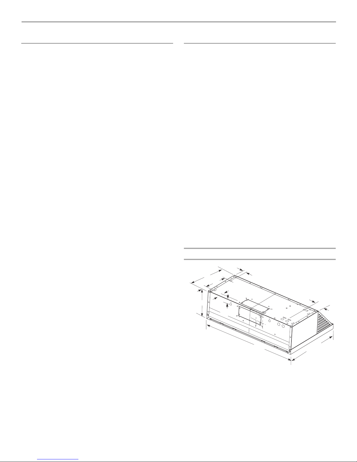
Product Dimensions
1³⁄₁₆"
⁵⁄₈"
(3.0 cm)
3" (7.6 cm) 30" (76.2 cm) model
5³⁄₄" (14.6 cm) 36" (91.4 cm) model
³⁄₄
"
19
(50.2 cm)
12"
(30.5 cm)
7¹⁄₄"
(18.4 cm)
2"
(5.1 cm)
9"
(22.9 cm)
29⁷⁄₈" (75.9 cm) - 30" (76.2 cm) model
35⁷⁄₈" (91.1 cm) - 36" (91.4 cm) model
(1.6 cm)
⁵⁄₈"
(1.6 cm)
5
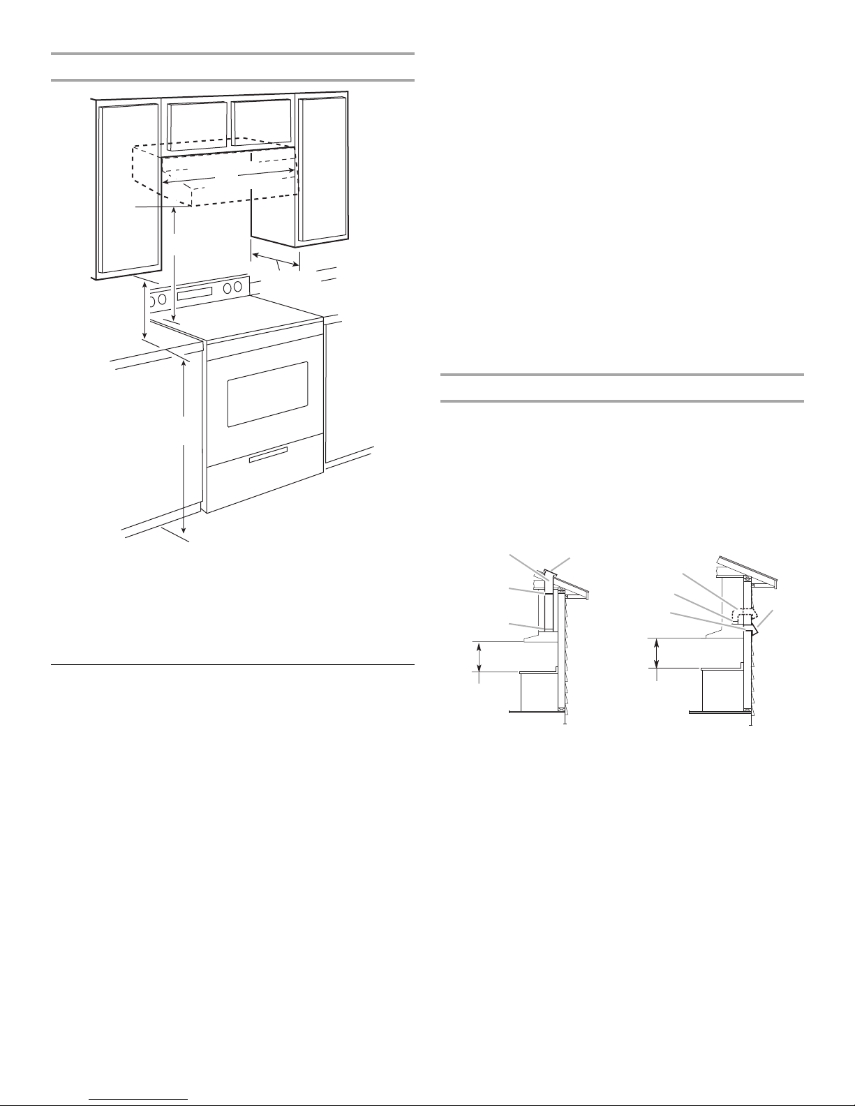
Installation Clearances
E
B
A
■ Use clamps to seal all joints in the vent system.
■ The vent system must have a damper. If roof or wall cap has a
damper, do not use damper supplied with the range hood.
■ Use caulking to seal exterior wall or roof opening around the
cap.
Cold Weather Installations
C
D
An additional back draft damper should be installed to minimize
backward cold air flow and a thermal break should be installed to
minimize conduction of outside temperatures as part of the vent
system. The damper should be on the cold air side of the thermal
break.
The break should be as close as possible to where the vent
system enters the heated portion of the house.
Makeup Air
Local building codes may require the use of make up air systems
when using ventilation systems greater than specified CFM of air
movement. The specified CFM varies from locale to locale.
Consult your HVAC professional for specific requirements in your
area.
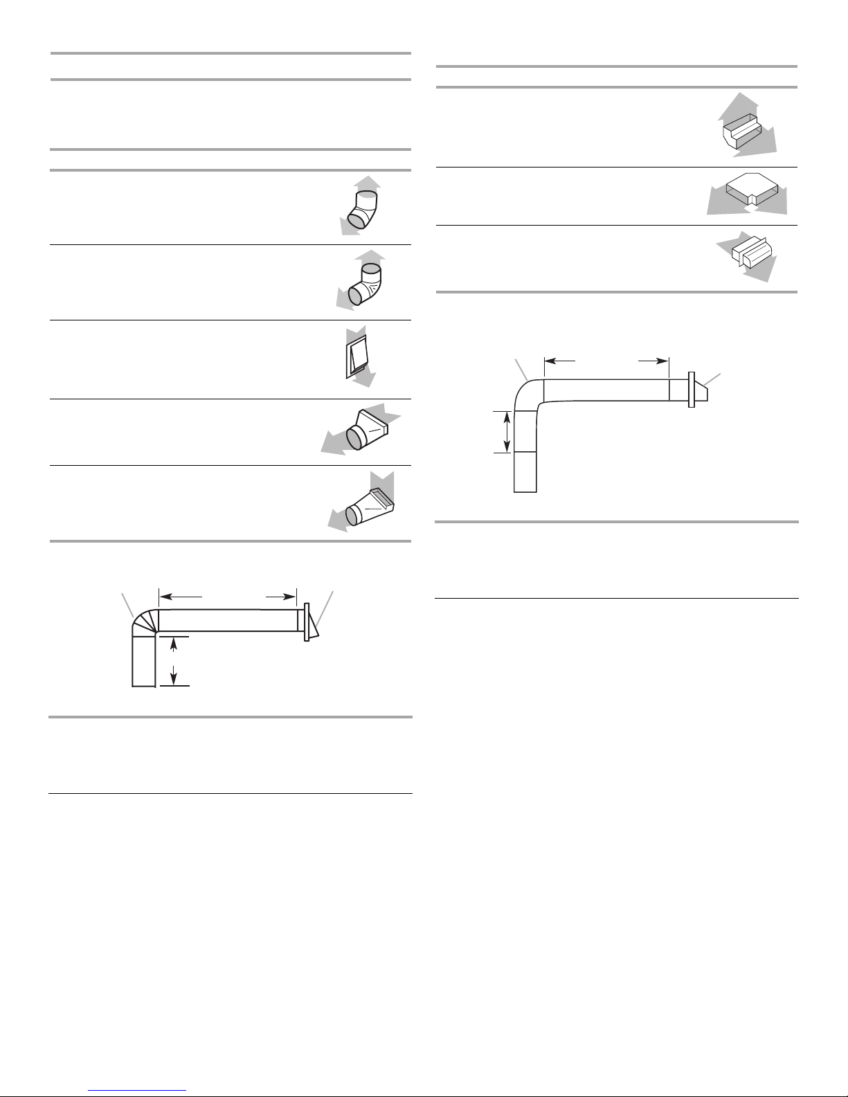
Venting Methods
E
A. 18" (45.7 cm) min. clearance - upper cabinet to countertop
B. 24" (61.0 cm) min. for electric cooking surfaces
27" (68.6 cm) min. for gas cooking surfaces
30" (76.2 cm) suggested max. - bottom of range hood to
cooking surface
C. 30" (76.2 cm) or 36" (91.4 cm) min. cabinet opening width
D. 13" (33.0 cm) cabinet depth
E. 36" (91.4 cm) base cabinet height
Venting Requirements
(Vented Models Only)
■ Vent system must terminate to the outdoors, except for non-
vented (recirculating) installations.
■ Do not terminate the vent system in an attic or other enclosed
area.
■ Do not use a 4" (10.2 cm) laundry-type wall cap.
■ Use a 6" (15.2 cm) or larger round metal vent or a 3¹⁄₄" x 10"
(8.3 x 25.4 cm) rectangular metal vent. Rigid metal vent is
recommended. Plastic or metal foil vent is not recommended.
■ The length of vent system and number of elbows should be
kept to a minimum to provide efficient performance.
For the most efficient and quiet operation:
■ Use no more than three 90° elbows.
■ Make sure there is a minimum of 24" (61 cm) of straight vent
between the elbows if more than 1 elbow is used.
■ Do not install 2 elbows together.
Vent system can terminate either through the roof or wall. Use
3¹⁄₄" x 10" (8.3 x 25.4 cm) with a maximum vent length of
35 ft (10.7 m) or 6" (15.2 cm) or larger round vent with a maximum
length of 50 ft (15.2 m) for vent system.
NOTE: Flexible vent is not recommended. Flexible vent creates
back pressure and air turbulence that gently reduces
performance.
Roof Venting Wall Venting
A
E
A
B
C
D
A. 6" (15.2 cm) or larger round
vent or a 3¹⁄₄" x 10" (8.3 x
25.4 cm) rectangular vent
through roof
B. Round vent: use 6" (15.2 cm)
or larger round damper
(purchased separately)
C. Round vent: use 3¹⁄₄" x 10" (8.3
x 25.4 cm) to 6" (15.2 cm) or
larger diameter transition piece
(purchased separately)
D. 24" (61.0 cm) - 30" (76.2 cm)
above electric cooking surface
27" (68.6 cm) - 30" (76.2 cm)
above gas cooking surface
E. Roof cap
B
C
D
A. 6" (15.2 cm) or larger round
vent or a 3¹⁄₄" x 10" (8.3 x
25.4 cm) rectangular vent
through the wall
B. Round vent: use 3¹⁄₄" x 10"
(8.3 x 25.4 cm) to 6" (15.2 cm)
or larger diameter transition
piece (purchased separately)
C. 3¹⁄₄" x 10" (8.3 x 25.4 cm)
through the wall
D. 24" (61.0 cm) - 30" (76.2 cm)
above electric cooking
surface
27" (68.6 cm) - 30" (76.2 cm)
above gas cooking surface
E. Wall cap
6
Calculating Vent System Length
To calculate the length of the system you need, add the
equivalent feet (meters) for each vent piece used in the system.
6" (15.2 cm) or Larger Round Vent System
Vent Piece Round
3¹⁄₄" x 10" (8.3 cm x 25.4 cm) Vent System
Vent Piece
3¹⁄₄" x 10" (8.3 cm x 25.4 cm)
90° elbow
5.0 ft
(1.5 m)
45° elbow 2.5 ft
(0.8 m)
90° elbow 5.0 ft
(1.5 m)
6" (15.2 cm) or larger
wall cap
3¹⁄₄" x 10" (8.3 cm x 25.4 cm)
to 6" (15.2 cm) or larger
3¹⁄₄" x 10" (8.3 cm x 25.4 cm)
to 6" (15.2 cm) or larger
0.0 ft
(0.0 m)
4.5 ft
(1.4 m)
5.0 ft
(1.5 m)
90° elbow
Example vent system
90˚ elbow
6 ft (1.8 m)
Wall cap
3¹⁄₄" x 10" (8.3 cm x 25.4 cm)
flat elbow
3¹⁄₄" x 10" (8.3 cm x 25.4 cm)
wall cap
12.0 ft
(3.7 m)
0.0 ft
(0.0 m)
Example vent system
3
¹⁄₄" x 10"
elbow
6 ft (1.8 m)
Wall cap
= 13.0 ft (3.9 m)
(8.3 x 25.4 cm)
2 ft
(0.6 m)
Maximum Recommended Length = 35 ft (10.7 m)
1 - 90° elbow = 5.0 ft (1.5 m)
8 ft (2.4 m) straight = 8.0 ft (2.4 m)
1 - wall cap = 0.0 ft (0.0 m)
Length of 3¹⁄₄" x 10" (8.3 cm x 25.4 cm)
system
2 ft (0.6 m)
Maximum Recommended Length = 50 ft (15.2 m)
1 - 90° elbow = 5.0 ft (1.5 m)
1 - wall cap = 0.0 ft (0.0 m)
8 ft (2.4 m) straight = 8.0 ft (2.4 m)
Length of 7" (17.8 cm) system = 13.0 ft (3.9 m)
7
Electrical Requirements
Observe all governing codes and ordinances.
Ensure that the electrical installation is adequate and in
conformance with National Electrical Code, ANSI/NFPA 70 (latest
edition), or CSA Standards C22.1-94, Canadian Electrical Code,
Part 1 and C22.2 No. 0-M91 (latest edition) and all local codes
and ordinances.
If codes permit and a separate ground wire is used, it is
recommended that a qualified electrician determine that the
ground path is adequate.
A copy of the above code standards can be obtained from:
National Fire Protection Association
One Batterymarch Park
Quincy, MA 02269
CSA International
8501 East Pleasant Valley Road
Cleveland, OH 44131-5575
■ A 120 volt, 60 Hz., AC only, 15-amp, fused electrical circuit is
required.
INSTALLATION INSTRUCTIONS
Prepare Location
NOTE: For vented installations, it is recommended that the vent
system be installed before hood is installed.
Before making cutouts, make sure there is proper clearance
within the ceiling or wall for exhaust vent.
NOTE: The exhaust adapter/damper can be installed up to
1" (2.5 cm) on either side of the hood center to accommodate
off-center ductwork.
1. Disconnect power.
2. Determine which venting method to use: roof or wall.
3. Select a flat surface for assembling the range hood. Place
covering over that surface.
■ If the house has aluminum wiring, follow the procedure
below:
1. Connect a section of solid copper wire to the pigtail
leads.
2. Connect the aluminum wiring to the added section of
copper wire using special connectors and/or tools
designed and UL listed for joining copper to aluminum.
Follow the electrical connector manufacturer's recommended
procedure. Aluminum/copper connection must conform with
local codes and industry accepted wiring practices.
■ Wire sizes and connections must conform with the rating of
the appliance as specified on the model/serial rating plate.
The model/serial plate is located behind the filter on the rear
wall of the range hood.
■ Wire sizes must conform to the requirements of the National
Electrical Code, ANSI/NFPA 70 (latest edition), or CSA
Standards C22. 1-94, Canadian Electrical Code, Part 1 and
C22.2 No. 0-M91 (latest edition) and all local codes and
ordinances.
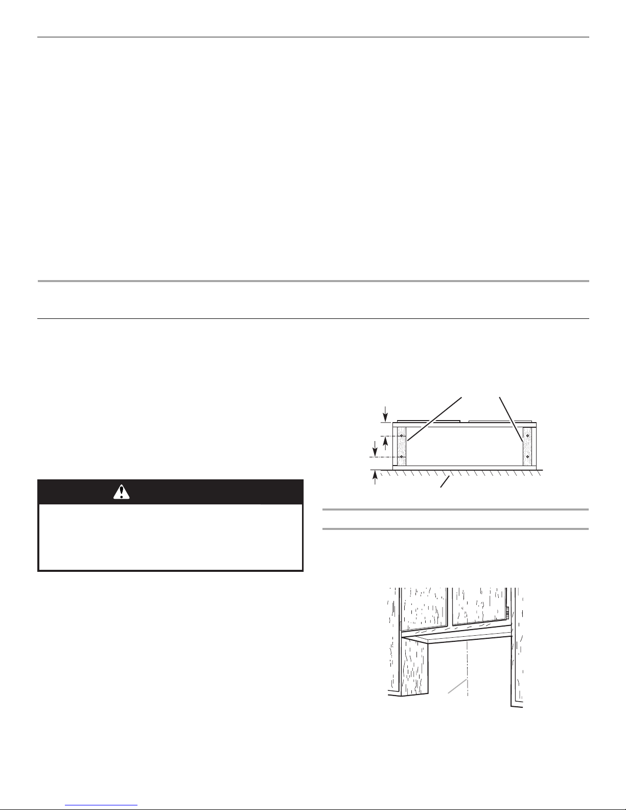
5. If cabinet has recessed bottom, add wood filler strips on each
side. Install screws to attach filler strips in locations shown.
Wood filler strips
(recessed cabinet
3" (7.6 cm)
bottoms only)
Cabinet
bottom
WARNING
Excessive Weight Hazard
Use two or more people to move and install
range hood.
Failure to do so can result in back or other injury.
4. Using 2 or more people, lift the range hood and set it upside
down onto covered surface.
3" (7.6 cm)
Wall
Determine Wiring Hole Location
Cut only one 1¹⁄₄" (3.2 cm) diameter wiring access hole. See
Step 2 for wiring hole location instructions.
1. Determine and clearly mark a vertical centerline on the wall
and cabinet in the area the vent opening will be made.
A
A. Centerline
8
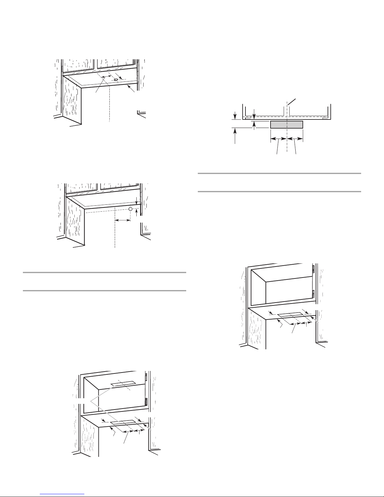
2. To wire through top:
Mark a line distance “A” from the right of the centerline on the
underside of the cabinet. Mark the point on this line that is
2" (5.0 cm) from back wall. Drill a 1¼" (3.0 cm) diameter hole
through the cabinet at this point.
A
Centerline
A. 10¹⁵⁄₁₆" (27.8 cm)
1¹⁄₄" (4.3 cm)
from wall,
not cabinet
frame
3. To wire through wall:
Mark a line distance “A” from the left of the centerline on the
wall. Mark the point on this line that is 1" (2.5 cm) from the
bottom of the cabinet. Drill a 1¹⁄₄" (3.0 cm) diameter hole
through the rear wall at this point.
1" (2.5 cm)
A
Centerline
A. 10¹⁵⁄₁₆" (27.8 cm)
Wall Venting
To make a 3¹⁄₂" x 10½" (8.9 cm x 26.7 cm) rectangle in the
wall:
1. Make 2 lines by measuring ³⁄₈" (0.9 cm) and 3⁷⁄₈" (9.8 cm)
down from underside of cabinet and mark on the centerline
on the back wall.
2. Mark lines 5¼" (13.3 cm) to the right and left of the centerline
on the wall.
3. Use saber or keyhole saw to cut a rectangular opening in the
wall for the vent.
Centerline
5¹⁄₄"
(13.3 cm)
3⁷⁄₈"
(9.8 cm)
³⁄₈"
(0.9 cm)
Cabinet
front
5¹⁄₄"
(13.3 cm)
Style 2 - Cut Openings for 3¼" x 10" (8.3 x 25.4 cm)
Rectangular Vent to Round Vent Transition
Roof Venting
To make a 4¹⁄₄" x 10½" (10.8 cm x 26.7 cm) rectangular cutout
on the underside of cabinet bottom:
1. Mark lines ¹⁄₂" (1.2 cm) and 4³⁄₄" (12.1 cm) from the back wall
on the centerline of the underside of cabinet.
2. Mark lines 5¼" (13.3 cm) to the right and left of the centerline
on the underside of cabinet.
3. Use saber or keyhole saw to cut a rectangular opening for
vent.
Style 1 - Cut Openings for 3¼" x 10" (8.3 cm x 25.4 cm)
Rectangular Vent System
Roof Venting
To make a 4¹⁄₄" x 10½" (10.8 cm x 26.7 cm) rectangular cutout
on the underside of cabinet top and bottom:
1. Mark lines ¹⁄₂" (1.2 cm) and 4³⁄₄" (12.1 cm) from the back wall
on the centerline of the underside of cabinet.
2. Mark lines 5¼" (13.3 cm) to the right and left of the centerline
on the underside of cabinet.
3. Use saber or keyhole saw to cut a rectangular opening for
vent.
4. Repeat steps 1-3 for the underside of the top of the cabinet.
Cabinet cutouts
*¹⁄₂" (1.2 cm)
*4³⁄₄"
(12.1 cm)
(13.3 cm)
5¹/₄"
5¹/₄"
(13.3 cm)
*¹⁄₂" (1.2 cm)
*4³⁄₄"
(12.1 cm)
(13.3 cm)
*From wall, not cabinet frame
5¹/₄"
5
¹/₄"
(13.3 cm)
To make a circular vent opening on the underside of the
cabinet top:
1. Mark a centerline on the underside of the top of cabinet.
2. Mark a line 5" (12.7 cm) from the back wall on the underside
of the top of cabinet.
3. Use a compass or a circle template to draw a circle with a
diameter that is ¼" (0.64 cm) larger than the vent.
*From wall, not cabinet frame
9
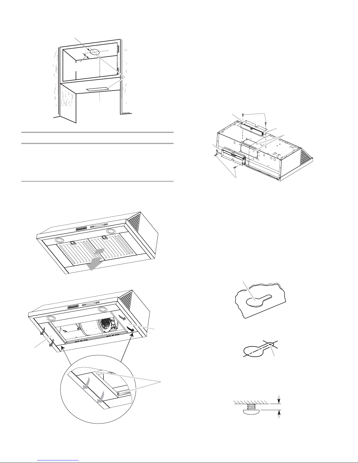
4. Use saber or keyhole saw to cut the circular vent opening.
B
Circular vent opening
*5"
(12.7 cm)
Cabinet
cutouts
*From wall, not
cabinet frame
Install Vent System
1. Install vent through the vent opening in upper cabinet or wall.
Complete venting system according to the selected venting
method. See “Venting Requirements” section.
2. Use caulking to seal exterior wall or roof opening around the
cap.
Install Range Hood
1. Remove the grease filters. See the “Range Hood Care”
section.
2. Remove mounting screws and lateral supports.
For vented installations:
■ Depending on your installation, remove either top or rear
rectangular vent knockout.
NOTE:
Do not remove rectangular knockouts if installation
of range hood is to be non-venting (recirculating).
■ Make sure damper pivot is nearest to top/back edge of
range hood.
■ Remove tape from damper flap.
NOTE: The exhaust adapter/damper can be installed up
to 1" (2.5 cm) on either side of the hood center to
accommodate off-center ductwork.
■ If using rectangular vent, attach rectangular damper/vent
connectors to the range hood using sheet metal screws.
A
E
B
A. Vertical vent
B. Sheet metal screws
■ If using round vent, attach vent transition piece
(purchased separately) to range hood top using sheet
metal screws.
NOTE: If the wall cap is directly behind the vent
connector, the dampers in the connector and wall cap
must not interfere with each other. Remove the vent
connector damper if they interfere.
3. Lift the range hood up under cabinet and determine final
location by centering beneath cabinet. Mark on the underside
of cabinet the location of the 4 keyhole mounting slots on the
range hood. Set range hood aside on a covered surface.
A
B
C
D
C. Hinge pin
D. Vent knockouts
E. Horizontal vent
A
A. Lateral supports
B. Mounting screws
10
A. Keyhole slot
A
4. Use ¹⁄₈" (3 mm) drill bit and drill 4 pilot holes as shown.
A
A. Drill pilot hole
5. Install the 4 - #10 x ⁵⁄₈" mounting screws in pilot holes. Leave
about ¹⁄₄" (6.4 cm) space between screw heads and cabinet
to slide range hood into place.
¹⁄₄"
(6.4 mm)
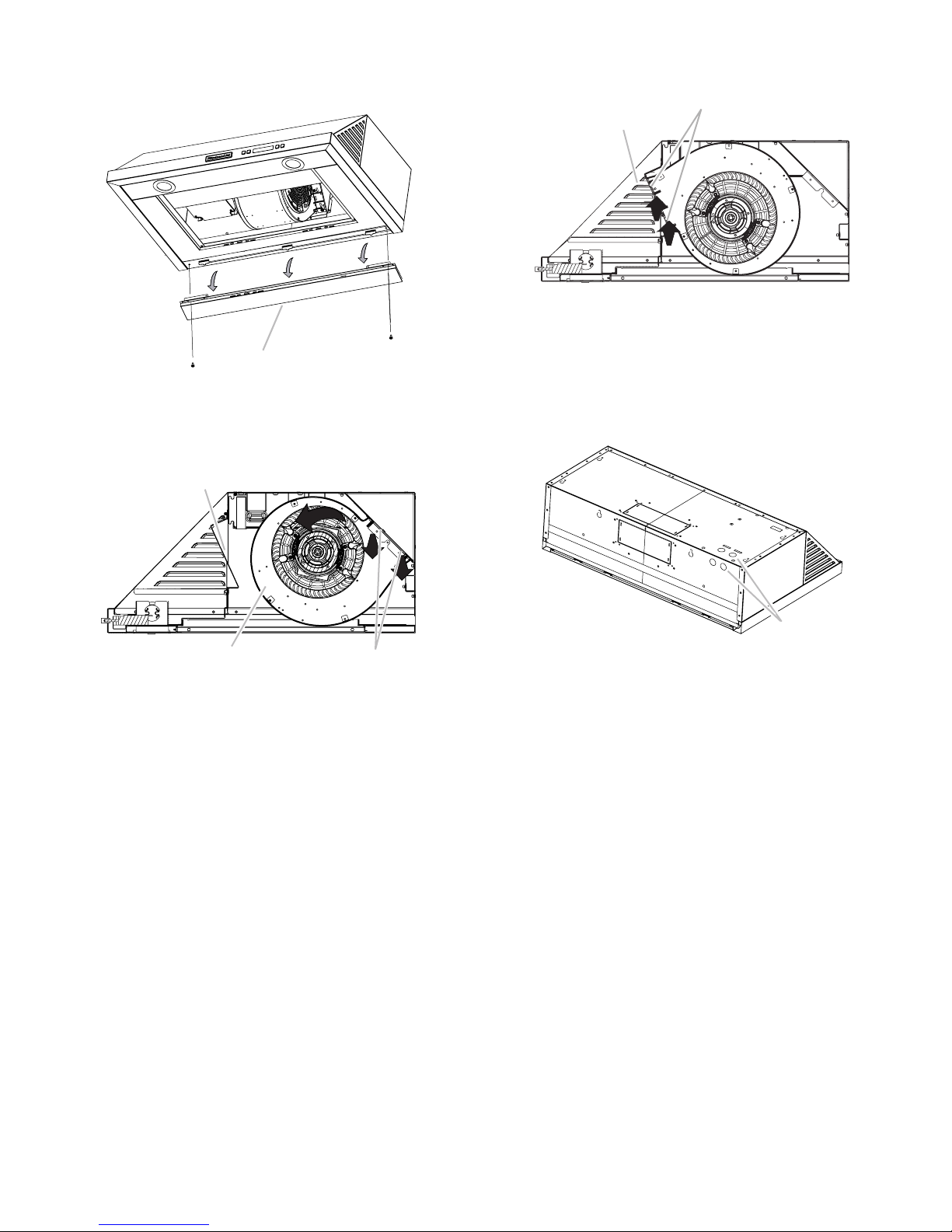
For non-vented (recirculating) installations, the blower
position must be changed:
■ Remove screws and rear support.
A
A. Rear support
■ Remove the blower mounting screws. Push up on the
blower to detach the blower from the mounting plate.
■ Remove the vent knockout from the front mounting plate.
A
■ Rotate the blower and attach to front mounting plate.
Install the blower mounting screws.
B
A
A. Blower mounting screws
B. Front mounting plate
■ Install charcoal filters. See the “Range Hood Care”
section.
6. Remove the round knockout from the top or back of the
range hood (depending on your wiring location) for the wiring
strain relief and install a ¹⁄₂" UL listed or CSA approved strain
relief.
C
A. Front mounting plate knockout
B. Blower mounting screws
C. Blower
A
B
A. Round knockout
7. Using 2 people, lift range hood into final location. Feed
enough electrical wire through the strain relief to make
connections in the terminal box. Tighten the strain relief
screws.
8. Position the range hood so that the large end of the keyhole
slots are over the mounting screws. Then push the hood
toward the wall so that the screws are in the neck of the slots.
The hood should be against the wall. Tighten the mounting
screws, making sure mounting screws are in the narrow neck
of the slots.
9. Check that damper, if used, rotates up and down freely.
11
 Loading...