

KitchenAid 30, 36"", KVWB600DSS, 30"" (76.2 CM) AND 36"" (91.4 CM)WALL-MOUNT CANOPY RANGE HOOD, KVWB600DBS Installation Instructions And Use & Care Manual
...
30" (76.2 CM) AND 36" (91.4 CM)
IMPORTANT: READ AND SAVE THESE INSTRUCTIONS.
FOR RESIDENTIAL USE ONLY.
IMPORTANT : LIRE ET CONSERVER CES INSTRUCTIONS.
POUR UTILISATION RÉSIDENTIELLE UNIQUEMENT.
LI315A/W10674118E
WALL-MOUNT CANOPY RANGE HOOD
Installation Instructions and Use & Care Guide
For questions about features, operation/performance, parts, accessories or service, call: 1-800-422-1230
In Canada, for assistance, installation and service, call: 1-800-807-6777
or visit our website at www.kitchenaid.com
or visit our website at www.kitchenaid.ca
HOTTE D'EXTRACTION À MONTAGE MURAL DE 30"
(76,2 CM) ET 36" (91,4 CM)
Instructions d’installation et Guide d’utilisation et d’entretien
Au Canada, pour assistance, installation ou service, composez le 1-800-807-6777
ou visitez notre site web à www.kitchenaid.ca
Table of Contents/Table des matières.............................................................................2
TABLE OF CONTENTS
You can be killed or seriously injured if you don't immediately
You
can be killed or seriously injured if you don't
follow
All safety messages will tell you what the potential hazard is, tell you how to reduce the chance of injury, and tell you what can
happen if the instructions are not followed.
Your safety and the safety of others are very important.
We have provided many important safety messages in this manual and on your appliance. Always read and obey all safety
messages.
This is the safety alert symbol.
This symbol alerts you to potential hazards that can kill or hurt you and others.
All safety messages will follow the safety alert symbol and either the word “DANGER” or “WARNING.”
These words mean:
follow instructions.
instructions.
DANGER
WARNING
State of California Proposition 65 Warnings:
WARNING: This product contains one or more chemicals known to the State of California to cause cancer.
WARNING: This product contains one or more chemicals known to the State of California to cause birth defects or other
reproductive harm.
TABLE DES MATIÈRES
RANGE HOOD SAFETY .................................................................2
INSTALLATION REQUIREMENTS ................................................4
Tools and Parts ............................................................................4
Location Requirements................................................................4
Venting Requirements..................................................................5
Electrical Requirements ...............................................................6
INSTALLATION INSTRUCTIONS ..................................................7
Prepare Location..........................................................................7
Install Range Hood.......................................................................8
Connect Vent System ..................................................................8
Make Electrical Connection .........................................................9
Install Vent Covers .....................................................................10
Complete Installation .................................................................10
RANGE HOOD USE......................................................................10
Controls and Features................................................................10
RANGE HOOD CARE ...................................................................11
Cleaning......................................................................................11
WIRING DIAGRAM ......................................................................13
ASSISTANCE OR SERVICE.........................................................14
In the U.S.A. ...............................................................................14
In Canada ...................................................................................14
Accessories................................................................................14
WARRANTY .................................................................................15
SÉCURITÉ DE LA HOTTE DE CUISINIÈRE................................16
EXIGENCES D’INSTALLATION...................................................18
Outils et pièces...........................................................................18
Exigences d’emplacement.........................................................18
Exigences concernant l’évacuation ...........................................19
Spécifications électriques ..........................................................20
INSTRUCTIONS D’INSTALLATION.............................................21
Préparation de l’emplacement...................................................21
Installation de la hotte ................................................................22
Raccordement du circuit d’évacuation......................................22
Raccordement électrique...........................................................23
Installation des cache-conduits .................................................24
Achever l’installation ..................................................................24
UTILISATION DE LA HOTTE .......................................................25
Commandes et caractéristiques................................................25
ENTRETIEN DE LA HOTTE..........................................................26
Nettoyage ...................................................................................26
SCHÉMA DE CÂBLAGE ..............................................................28
ASSISTANCE OU SERVICE.........................................................29
Au Canada..................................................................................29
Accessoires ................................................................................29
GARANTIE.....................................................................................30
RANGE HOOD SAFETY
2
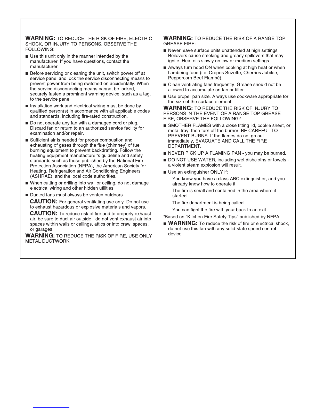
IMPORTANT SAFETY INSTRUCTIONS
READ AND SAVE THESE INSTRUCTIONS
3
INSTALLATION REQUIREMENTS
†®TORX and T10 are registered trademarks of Acument Intellectual Properties, LLC.
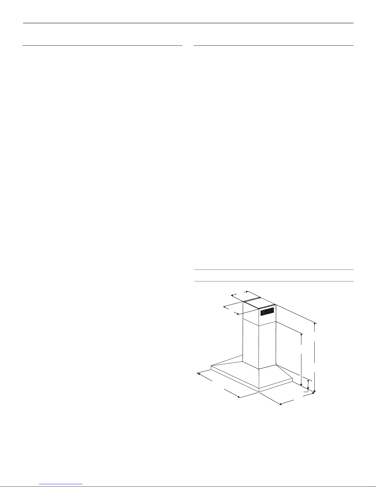
10¾" (27.3 cm)
13³⁄₁₆" (33.5 cm)
*28⁵⁄₁₆" (71.9 cm) min.
42⁵⁄₈" (108.3 cm) max.
**24⁵⁄₈" (62.5 cm) min.
38¾" (98.4 cm) max.
24"
(60.8 cm)
5"
(12.7 cm)
19¹¹⁄₁₆" (50.0 cm)
30" (76.2 cm)
36" (91.4 cm)
Tools and Parts
Gather the required tools and parts before starting installation. Read
and follow the instructions provided with any tools listed here.
Tools Needed
■ Level
■ Drill with 1¼" (3.0 cm), ³⁄₈" (9.5 mm), and ⁵⁄₁₆" (7.9 mm)
drill bits
■ Pencil
■ Wire stripper or utility knife
■ Tape measure or ruler
■ Pliers
■ Caulking gun and weatherproof caulking compound
■ Vent clamps
■ Jigsaw or keyhole saw
■ Flat-blade screwdriver
■ Metal snips
■ Phillips screwdriver
Parts Needed
■ Home power supply cable
■ ½" (12.7 mm) UL listed or CSA approved strain relief
■ UL listed wire connectors (3)
For Vented Installations, You Will Also Need:
■ 1 wall or roof cap
■ Metal vent system
For Non-Vented (Recirculating) Installations, You Will Also
Need:
■ Recirculation Kit Part Number W10692908 for non-vented
(recirculating) installations only. See “Assistance or Service”
section to order.
■ 6" (15.2 cm) diameter round metal vent duct - length required
is determined by ceiling height.
Parts Supplied
Remove parts from packages. Check that all parts are included.
■ Hood canopy assembly with ventilator and LED and halogen
lights installed
■ Vent transition with back draft dampers installed
■ Metal grease filter(s)—depending on model and size
■ Vent cover support bracket
■ Mounting template
■ 2-piece vent cover
■ 4.2 x 8 mm screws (4)
■ 5 x 45 mm mounting screws (6)
■ D6.4 x 18 mm washers (2)
■ 8 x 40 mm wall anchors (2)
■ 10 x 50 mm wall anchors (4)
■ 3.5 x 9.5 mm sheet metal screws (2)
■ T10 TORX
®†
adapter
Location Requirements
IMPORTANT: Observe all governing codes and ordinances.
Have a qualified technician install the range hood. It is the
installer's responsibility to comply with installation clearances
specified on the model/serial/rating plate. The model/serial/rating
plate is located behind the left filter on the rear wall of the vent
hood.
Canopy hood location should be away from strong draft areas,
such as windows, doors and strong heating vents.
Cabinet opening dimensions that are shown must be used. Given
dimensions provide minimum clearance.
This range hood is recommended for use with cooktops with a
maximum total rating of 65,000 BTUs or less.
Grounded electrical outlet is required. See “Electrical
Requirements” section.
The canopy hood is factory-set for venting through the roof or
wall. For non-vented (recirculating) installation, see “For nonvented (recirculating) installation only” in the “Connect Vent
System” section. Recirculation Kit Part Number W10692908 is
available from your dealer or an authorized parts distributor.
All openings in ceiling and wall where canopy hood will be
installed must be sealed.
For Mobile Home Installations
The installation of this range hood must conform to the
Manufactured Home Construction Safety Standards, Title 24
CFR, Part 328 (formerly the Federal Standard for Mobile Home
Construction and Safety, Title 24, HUD, Part 280) or when such
standard is not applicable, the standard for Manufactured Home
Installation 1982 (Manufactured Home Sites, Communities and
Setups) ANSI A225.1/NFPA 501A, or latest edition, or with local
codes.
Product Dimensions
*For non-vented (recirculating) installations
**For vented installations
4
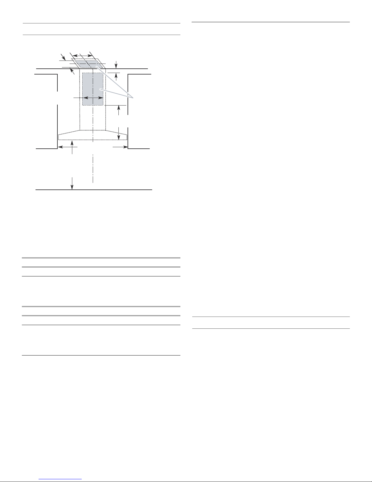
Cabinet Dimensions
10" (25.4 cm) min.
13" (33.0 cm) max.
9¹⁄₂" (24.1 cm)
2" (5.1 cm) min.
9" (22.9 cm) min.*
Centerline
Side
cabinet
Side
cabinet
Vent and power
supply cable
entry location
17" (43.2 cm)*
30" (76.2 cm) or
36" (91.4 cm)
"X"
bottom of
canopy
to cooking
surface
10" (25.4 cm) min.
13" (33.0 cm) max.
Cooking surface
*For non-vented (recirculating) installations
IMPORTANT:
Minimum distance “X”: 24" (61.0 cm) from electric cooking
surface.
Minimum distance “X”: 27" (68.6 cm) from gas cooking
surfaces.
Suggested maximum distance “X”: 36" (91.4 cm)
The chimneys can be adjusted for different ceiling heights. See
the following chart.
Electric cooking
surface
Gas cooking
surface
Electric cooking
surface
Gas cooking
surface
*NOTE: The range hood chimneys are adjustable and designed
to meet varying ceiling or soffit heights depending on the
distance “X” between the bottom of the range hood and the
cooking surface. For higher ceilings, a Stainless Steel Chimney
Extension Kit Part Number W10272075 is available from your
dealer or an authorized parts distributor. The chimney extension
replaces the chimney shipped with the range hood.
Vented Installations
Min. ceiling height Max. ceiling height
7' 1" (2.16 m) 9' 2" (2.79 m)
7' 4" (2.23 m) 9' 2" (2.79 m)
Non-vented (recirculating) Installations
Min. ceiling height Max. ceiling height
7' 1" (2.16 m) 9' 6" (2.9 m)
7' 4" (2.23 m) 9' 6" (2.9 m)
Venting Requirements
(Vented Models Only)
■ Vent system must terminate to the outdoors, except for non-
vented (recirculating) installations.
■ Do not terminate the vent system in an attic or other enclosed
area.
■ Do not use 4" (10.2 cm) laundry-type wall caps.
■ Use metal vent only. Rigid metal vent is recommended.
Plastic or metal foil vent is not recommended.
■ The length of vent system and number of elbows should be
kept to a minimum to provide efficient performance.
For the Most Efficient and Quiet Operation:
■ Use no more than three 90° elbows.
■ Make sure there is a minimum of 24" (61.0 cm) of straight
vent between the elbows, if more than 1 elbow is used.
■ Do not install 2 elbows together.
■ Use clamps to seal all joints in the vent system.
■ The vent system must have a damper. If the roof or wall cap
has a damper, do not use the damper supplied with the range
hood.
■ Use caulking to seal exterior wall or roof opening around the
cap.
■ The size of the vent should be uniform.
Cold Weather Installations
An additional back draft damper should be installed to minimize
backward cold airflow and a thermal break should be installed to
minimize conduction of outside temperatures as part of the vent
system. The damper should be on the cold air side of the thermal
break.
The break should be as close as possible to where the vent
system enters the heated portion of the house.
Makeup Air
Local building codes may require the use of makeup air systems
when using ventilation systems greater than specified CFM of air
movement. The specified CFM varies from locale to locale.
Consult your HVAC professional for specific requirements in your
area.
Venting Methods
This canopy range hood is factory set for venting through the roof
or through the wall.
A 6" (15.2 cm) round vent system is needed for installation (not
included). The hood exhaust opening is 6" (15.2 cm) round.
NOTE: Flexible vent is not recommended. Flexible vent creates
back pressure and air turbulence that greatly reduce
performance.
Vent system can terminate either through the roof or wall. To vent
through a wall, a 90° elbow is needed.
Rear Discharge
A 90° elbow may be installed immediately above the hood.
For Non-Vented (Recirculating) Installations
If it is not possible to vent cooking fumes and vapors to the
outside, the hood can be used in the non-vented (recirculating)
version, using a Recirculation Kit (which includes charcoal filters
and a deflector). To order, see the “Assistance or Service”
section.
5
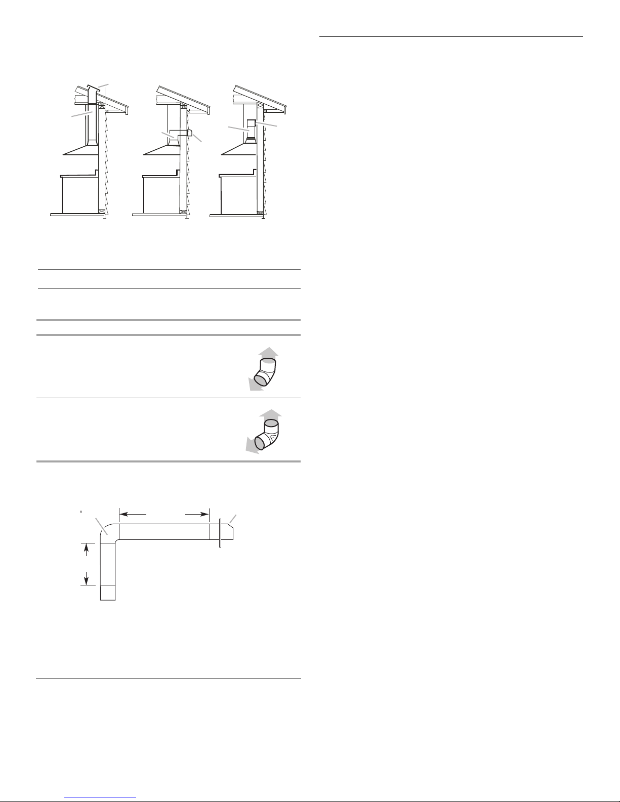
Non-Vented
A
A
B
B
B
A
90 elbow
6 ft (1.8 m)
2 ft
(0.6 m)
Wall cap
Roof Venting Wall Venting
A. Roof cap
B. 6" (15.2 cm)
round vent
A. Wall cap
B. 6" (15.2 cm)
round vent
(Recirculating)
A. Diverter
B. 6" (15.2 cm)
round vent
Calculating Vent System Length
To calculate the length of the system you need, add the
equivalent feet (meters) for each vent piece used in the system.
Vent Piece 6" (15.2 cm) Round
45° elbow 2.5 ft
(0.8 m)
90° elbow 5.0 ft
(1.5 m)
Maximum equivalent vent length is 35 ft (10.7 m).
Electrical Requirements
Observe all governing codes and ordinances.
Ensure that the electrical installation is adequate and in
conformance with National Electrical Code, ANSI/NFPA 70 (latest
edition), or CSA Standards C22.1-94, Canadian Electrical Code,
Part 1 and C22.2 No. 0-M91 (latest edition) and all local codes
and ordinances.
If codes permit and a separate ground wire is used, it is
recommended that a qualified electrician determine that the
ground path is adequate.
A copy of the above code standards can be obtained from:
National Fire Protection Association
1 Batterymarch Park
Quincy, MA 02169-7471
CSA International
8501 East Pleasant Valley Road
Cleveland, OH 44131-5575
■ A 120 volt, 60 Hz., AC only, 15-amp, fused electrical circuit is
required.
■ If the house has aluminum wiring, follow the procedure
below:
1. Connect a section of solid copper wire to the pigtail
leads.
2. Connect the aluminum wiring to the added section of
copper wire using special connectors and/or tools
designed and UL listed for joining copper to aluminum.
Follow the electrical connector manufacturer's recommended
procedure. Aluminum/copper connection must conform with
local codes and industry accepted wiring practices.
■ Wire sizes and connections must conform with the rating of
the appliance as specified on the model/serial rating plate.
The model/serial plate is located behind the filter on the rear
wall of the range hood.
■ Wire sizes must conform to the requirements of the National
Electrical Code, ANSI/NFPA 70 (latest edition), or CSA
Standards C22. 1-94, Canadian Electrical Code, Part 1 and
C22.2 No. 0-M91 (latest edition) and all local codes and
ordinances.
Example Vent System
The following example falls within the maximum recommended
vent length of 35 ft (10.7 m).
1 - 90° elbow = 5.0 ft (1.5 m)
1 - wall cap = 0.0 ft (0.0 m)
8 ft (2.4 m) straight = 8.0 ft (2.4 m)
Length of system = 13.0 ft (3.9 m)
6
INSTALLATION INSTRUCTIONS
WARNING
Excessive Weight Hazard
Use two or more people to move and install
range hood.
Failure to do so can result in back or other injury.
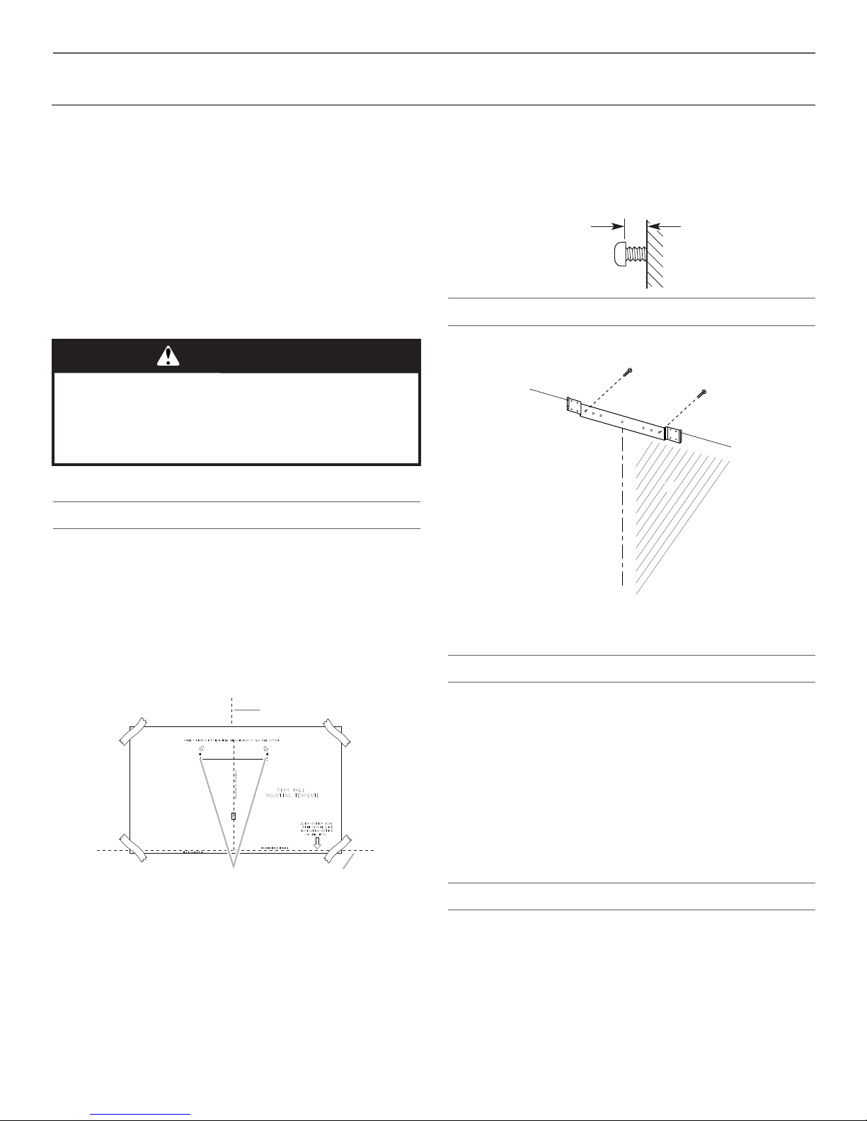
Vertical Centerline
C
L
LLAW RAER
ETALPMET GNITNUOM
EGDE MOTTOB NGILA
ENIL LICNEP HTIW
MOTTOB GNITACIDNI
DOOH EHT FO
thgieH noitallatsnI
TROPPUS LLAW RAER RO SDUTS HGUORHT SELOH TOLIP "61/3 )OWT( 2 LLIRD
eniL latnoziroH
A
C
B
¹⁄₄"
(6.4 mm)
A
C
B
Prepare Location
■ It is recommended that the vent system be installed before
hood is installed.
■ Before making cutouts, make sure there is proper clearance
within the ceiling or wall for exhaust vent.
■ Check your ceiling height and the hood height maximum
before you select your hood.
1. Disconnect power.
2. Determine which venting method to use: roof, wall, or non-
vented.
3. Select a flat surface for assembling the range hood. Place
covering over that surface.
4. Using 2 or more people, lift range hood onto covered surface.
5. Drill ³⁄₁₆" (4.8 mm) pilot holes at all locations where screws are
being installed into wood.
6. Install the 2 - 5 x 45 mm mounting screws. Leave a ¹⁄₄"
(6.4 mm) gap between the wall and the back of the screw
head to slide range hood into place.
Vent Cover Bracket Installation
7. Attach vent cover bracket to wall flush to the ceiling using
2 - 5 x 45 mm screws.
Range Hood Mounting Screws Installation
1. Determine and mark the centerline on the wall where the
canopy hood will be installed.
2. Select a mounting height between a minimum of 24"
(61.0 cm) for an electric cooking surface, a minimum of 27"
(68.6 cm) for a gas cooking surface, and a suggested
maximum of 36" (91.4 cm) above the range to the bottom of
the hood. Mark a reference line on the wall.
3. Tape template in place, aligning the template centerline and
bottom of template with hood bottom line and with the
centerline marked on the wall.
A. Centerline
B. Fastener locations
C. Mounting height reference (hood bottom line)
4. Mark centers of the fastener locations through the template
to the wall.
IMPORTANT: All screws must be installed into wood. If there
is no wood to screw into, additional wall framing supports
may be required.
Remove the template.
A. Ceiling
B. Wall
C. Centerline
Complete Preparation
1. Determine and make all necessary cuts in the wall for the vent
system. Install the vent system before installing the hood. See
“Venting Requirements” section.
2. Determine the required height for the home power supply
cable and drill a 1¼" (3.2 cm) hole at this location.
3. Run the home power supply cable according to the National
Electrical Code or CSA Standards and local codes and
ordinances. There must be enough ½" conduit and wires from
the fused disconnect (or circuit breaker) box to make the
connection in the hood’s electrical terminal box.
NOTE: Do not reconnect power until installation is complete.
4. Use caulk to seal all openings.
Install In-Line Smart Kit - Optional
NOTE: Your range hood can work with either an internal or an in-
line (external) blower motor system. An optional In-Line Smart Kit
(purchased separately) allows the blower motor that comes with
this range hood to be installed in a location other than inside the
range hood cavity.
CAUTION: To reduce the risk of fire and electric shock, install this
range hood only with the In-Line Smart Kit manufactured by
Whirlpool, part number W10692945.
For installation see the In-Line Smart Kit installation instructions.
See the “Assistance or Service” section to order.
7
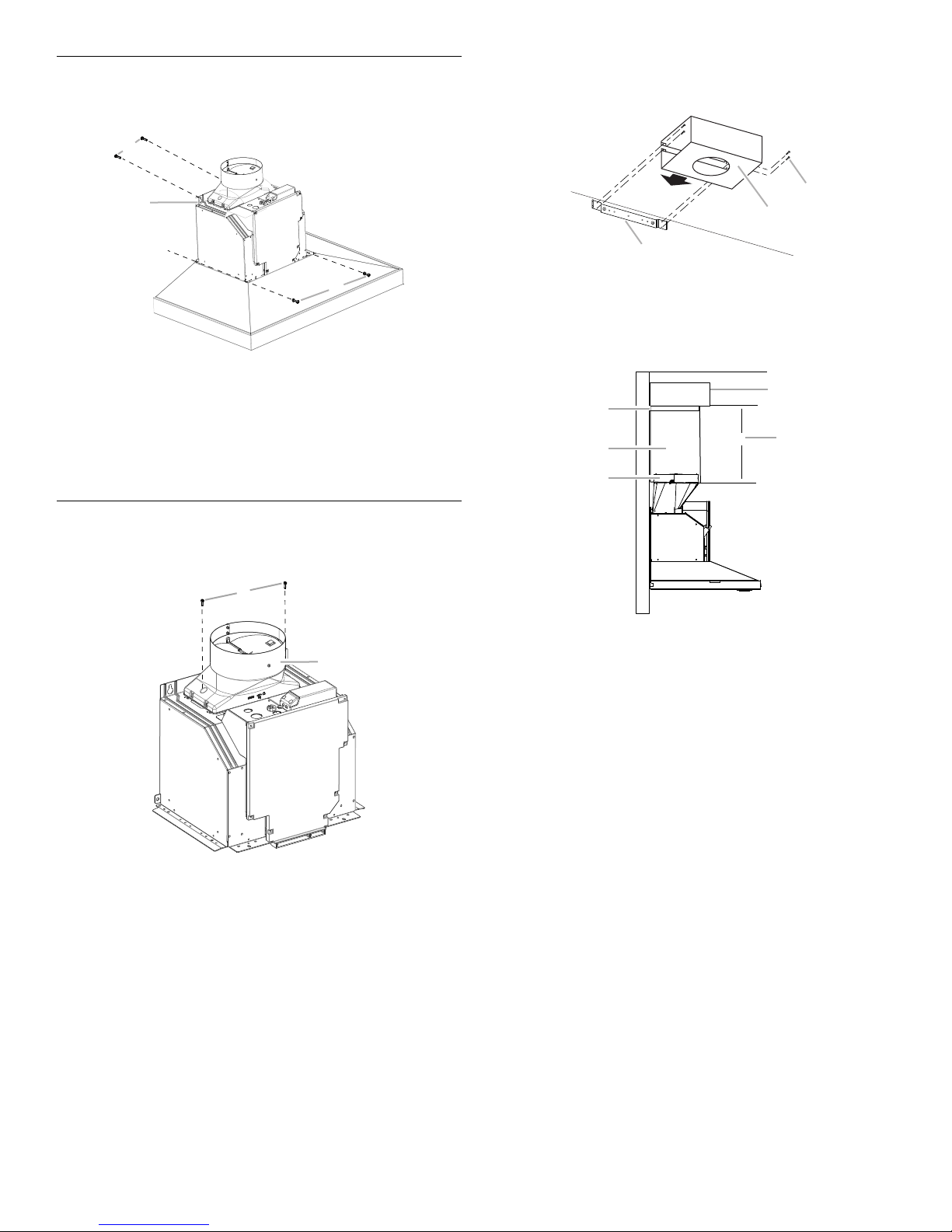
Install Range Hood
A
B
C
B
A
A
B
C
X
A
C
D
B
E
1. Using 2 or more people, hang range hood on 2 mounting
screws through the mounting slots on back of hood.
A. Mounting screws
B. Mounting slots
C. Lower mounting screws and washers
2. Remove the grease filter. See “Range Hood Care” section.
3. Level the range hood and tighten upper mounting screws.
4. Install 2 - 5 x 45 mm lower mounting screws and 2 -
D6.4 x 18 mm washers, and then tighten.
For Non-Vented (Recirculating) Installation Only:
1. Assemble the air deflector with the duct cover bracket using
4 - 4.2 x 8 mm screws.
A. Assembly screws
B. Air deflector
C. Duct cover bracket
2. Measure from the bottom of the air deflector to the bottom of
the hood outlet.
Connect Vent System
1. Install transition on top of hood (if removed for shipping) with
2 - 3.5 x 9.5 mm sheet metal screws.
A. Vent transition
B. 3.5 x 9.5 mm screw
For Vented Installations Only:
1. Fit vent system over the exhaust outlet.
2. Seal connection with clamps.
3. Check that back draft dampers work properly.
A. Air deflector
B. Vent clamp
C. X = length to cut vent duct
D. Vent duct
E. Exhaust outlet
3. Cut the duct to the measured size (X).
4. Remove the air deflector.
5. Slide the duct onto the bottom of the air deflector.
6. Place the assembled air deflector and duct over the exhaust
outlet from the hood.
7. Reassemble the air deflector to the duct cover bracket with
the 4 assembly screws.
8. Seal connections with vent clamps.
8
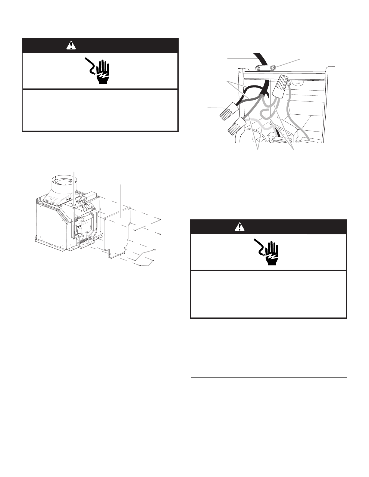
Make Electrical Connection
WARNING
Electrical Shock Hazard
Disconnect power before servicing.
Replace all parts and panels before operating.
Failure to do so can result in death or electrical shock.
C
A
B
C
D
E
F
WARNING
Electrical Shock Hazard
Electrically ground blower.
Connect ground wire to green and yellow ground wire
in terminal box.
Failure to do so can result in death or electrical shock.
1. Disconnect power.
2. Remove terminal box cover.
3. Remove the knockout in the terminal box cover and install a
UL listed or CSA approved ¹⁄₂" (12.7) strain relief.
A
B
4. Run home power supply cable through strain relief into
terminal box.
A. Home power supply cable
B. UL listed or CSA approved
strain relief
C. Black wires
5. Use UL listed wire connectors and connect black wires (C)
together.
6. Use UL listed wire connectors and connect white wires (E)
together.
D. UL listed wire connectors
E. White wires
F. Green (or bare) and yellow-
green ground wires
A. Knockout
B. Terminal box cover
C. Screws (7)
C
C
C
7. Connect green (or bare) ground wire from home power supply
to yellow-green ground wire (F) in terminal box using UL listed
wire connectors.
8. Tighten strain relief screw.
9. Install terminal box cover.
10. Check that all light bulbs are secure in their sockets.
11. Reconnect power.
Optional Power Cord Kit Installations
For optional power cord kit installations, follow the instructions
supplied with the power cord kit. See the “Assistance or Service”
section for information on ordering.
NOTE: Use only with range hood cord connection kits that have
been investigated and found acceptable for use with this model
range hood.
9
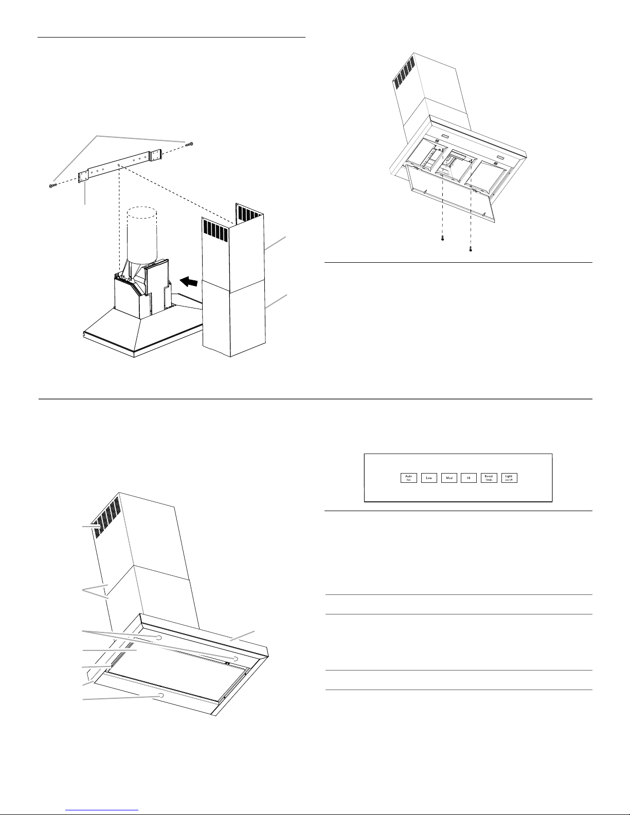
Install Vent Covers
A
B
C
D
A
B
C
D
E
F
G
H
When using both upper and lower vent covers, push lower cover
down onto hood and lift upper cover to ceiling, and then install
with two 4.2 x 8 mm screws.
NOTE: For vented installations, the upper vent cover may be
reversed to hide slots.
A. Upper vent cover
B. Lower vent cover
C. 4.2 x 8 mm screws
D. Bracket
Secure the bottom of the duct with 2 - 4.2 x 8 mm screws.
Complete Installation
1. For non-vented (recirculating) installations only, install
charcoal filters over grille on blower housing. See the “Range
Hood Care” section.
2. Install metal filters. See the “Range Hood Care” section.
3. Check the operation of the range hood blower and light. See
the “Range Hood Use” section.
NOTE: To get the most efficient use from your new range hood,
read the “Range Hood Use” section.
The range hood is designed to remove smoke, cooking vapors and
odors from the cooktop area. For best results, start the hood before
cooking and allow it to operate several minutes after the cooking is
complete to clear all smoke and odors from the kitchen.
The range hood controls are located on the front side of the canopy.
A. Louver holes (non-vented
[recirculating] installations only)
B. Duct covers
C. LED lights (2)
D. Perimetric cover
10
E. Metal grease filters
F. Canopy
G. Halogen light
H. Control panel
RANGE HOOD USE
Control Panel
NOTES:
■ To activate the controls, press and release the desired button.
■ The control feature button will be lit when a control feature is
turned On.
Sleep Mode
The range hood automatically enters Sleep Mode when not in
use. After 10 minutes of no range hood activity, all of the control
button lights will turn Off. To deactivate Sleep Mode, press any
button.
(located behind the
perimetric cover)
Auto Sense
Auto Sense allows the range hood fan to turn on automatically
when it senses heat higher than its allowable temperature limit.
When Auto Sense is On, the fan speed will increase or decrease
based on the temperature Auto Sense is measuring.
Auto Sense can be manually increased by pressing a higher fan
speed. The fan will run at the selected speed for 10 minutes
before returning to the speed selected for Auto Sense.
Controls and Features
 Loading...