


Kitchenaid KVUB600DSS Owners Manual
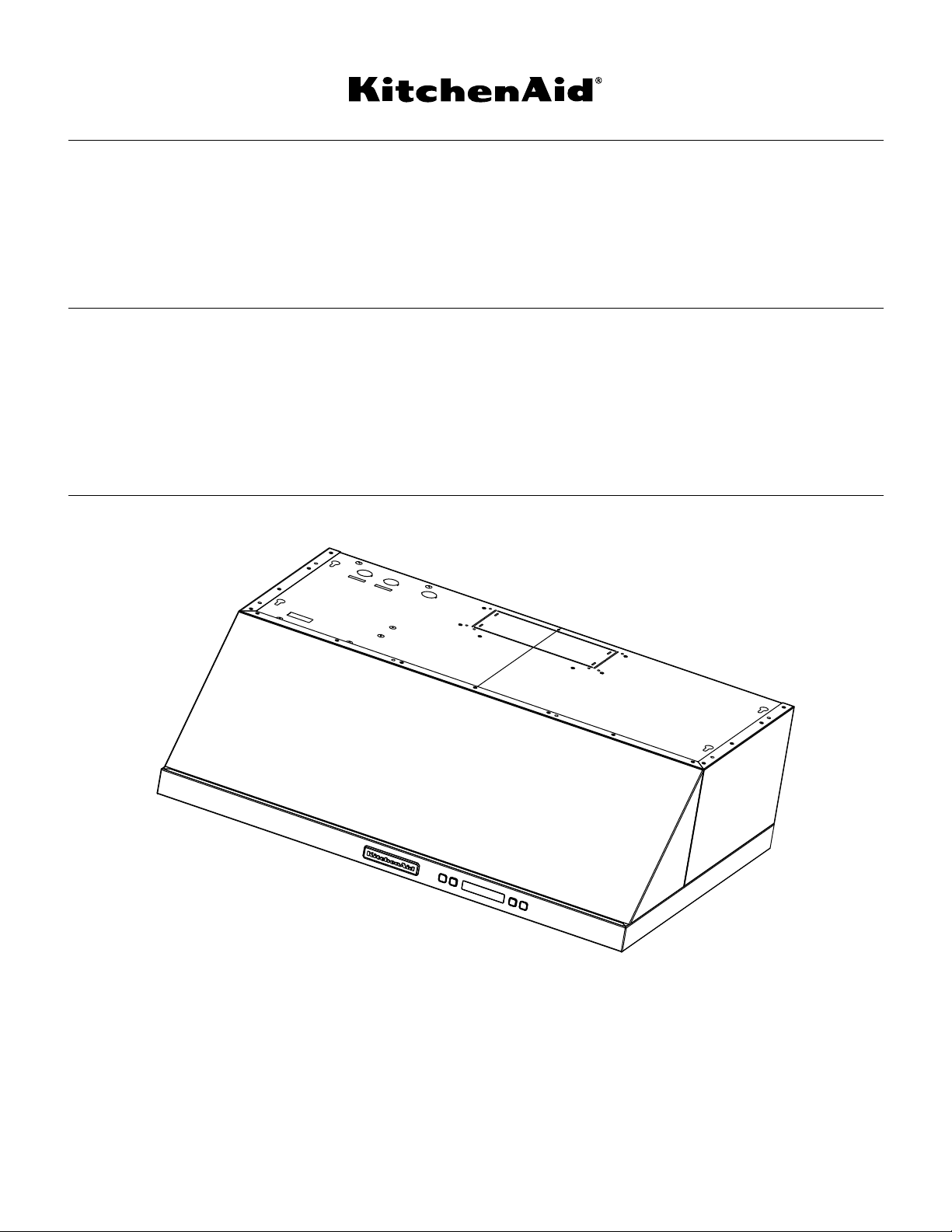
30" (76.2 CM) AND 36" (91.4 CM) RANGE HOOD
LI32NC/W10674120C
IMPORTANT: READ AND SAVE THESE INSTRUCTIONS.
FOR RESIDENTIAL USE ONLY.
IMPORTANT : LIRE ET CONSERVER CES INSTRUCTIONS.
POUR UTILISATION RÉSIDENTIELLE UNIQUEMENT.
Installation Instructions and Use & Care Guide
For questions about features, operation/performance, parts, accessories or service, call: 1-800-422-1230
In Canada, for assistance, installation and service, call: 1-800-807-6777
or visit our website at...
www.kitchenaid.com or www.kitchenaid.ca
HOTTE DE CUISINIÈRE
30" (76,2 CM) ET 36" (91,4 CM)
Instructions d’installation et Guide d’utilisation et d’entretien
Au Canada, pour assistance, installation ou service composez le 1-800-807-6777
Table of Contents/Table des matières.............................................................................2
ou visitez notre site web à...
www.kitchenaid.ca
TABLE OF CONTENTS
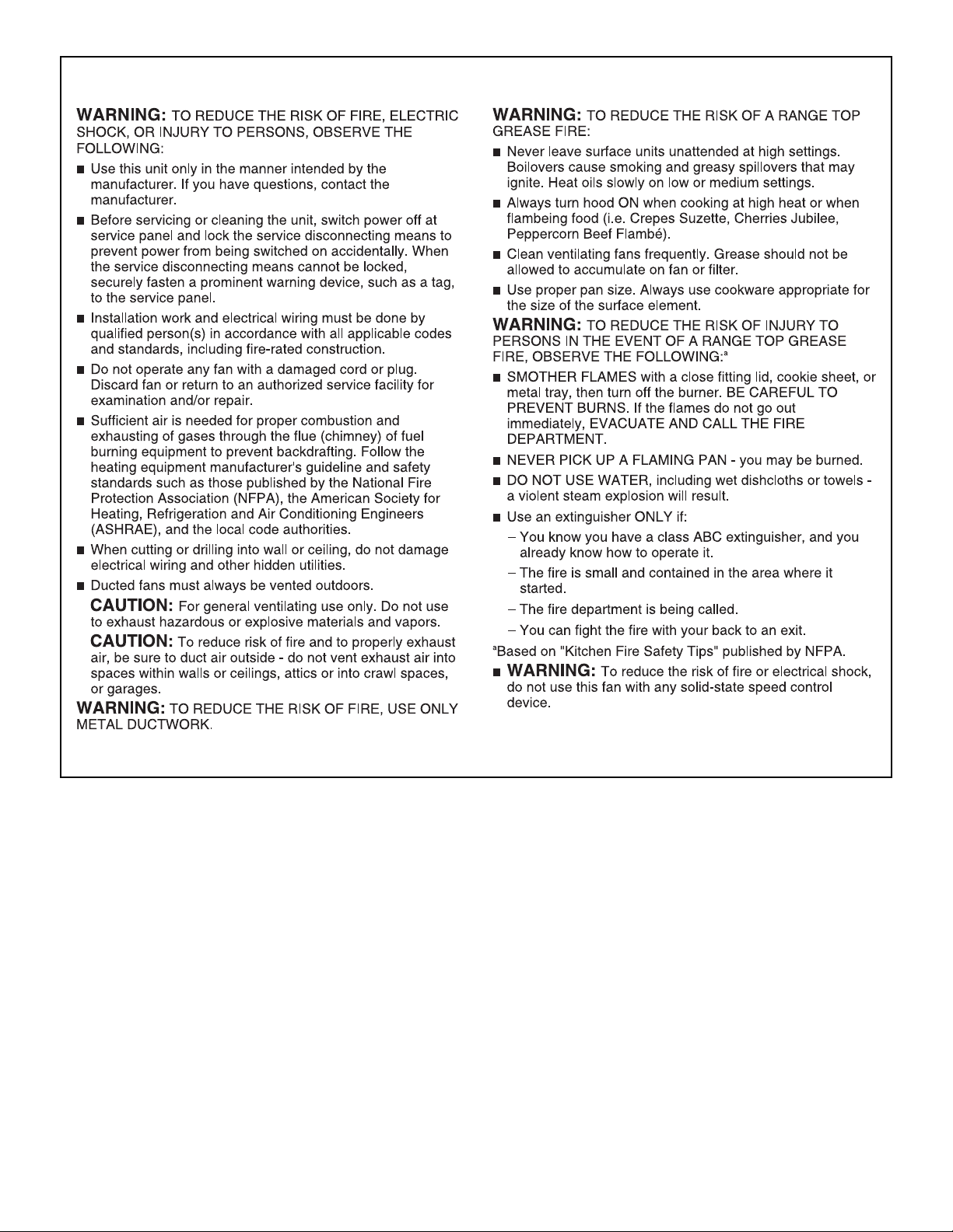
You can be killed or seriously injured if you don't immediately
You
can be killed or seriously injured if you don't
follow
All safety messages will tell you what the potential hazard is, tell you how to reduce the chance of injury, and tell you what can
happen if the instructions are not followed.
Your safety and the safety of others are very important.
We have provided many important safety messages in this manual and on your appliance. Always read and obey all safety
messages.
This is the safety alert symbol.
This symbol alerts you to potential hazards that can kill or hurt you and others.
All safety messages will follow the safety alert symbol and either the word “DANGER” or “WARNING.”
These words mean:
follow instructions.
instructions.
DANGER
WARNING
State of California Proposition 65 Warnings:
WARNING: This product contains one or more chemicals known to the State of California to cause cancer.
WARNING: This product contains one or more chemicals known to the State of California to cause birth defects or other
reproductive harm.
TABLE DES MATIÈRES
RANGE HOOD SAFETY .................................................................2
INSTALLATION REQUIREMENTS ................................................4
Tools and Parts ............................................................................4
Location Requirements................................................................4
Venting Requirements..................................................................5
Electrical Requirements ...............................................................7
INSTALLATION INSTRUCTIONS ..................................................7
Prepare Location..........................................................................7
Install Range Hood.......................................................................9
Make Electrical Connection .......................................................11
Complete Installation .................................................................11
RANGE HOOD USE......................................................................11
Display........................................................................................12
Light............................................................................................12
Timer...........................................................................................12
Fan Speed ..................................................................................12
RANGE HOOD CARE ...................................................................13
Cleaning......................................................................................13
WIRING DIAGRAM ......................................................................14
ASSISTANCE OR SERVICE.........................................................15
In the U.S.A. ...............................................................................15
In Canada ...................................................................................15
Accessories................................................................................15
WARRANTY ..................................................................................16
SÉCURITÉ DE LA HOTTE DE CUISINIÈRE................................17
EXIGENCES D’INSTALLATION...................................................19
Outillage et pièces......................................................................19
Exigences d'emplacement.........................................................19
Exigences concernant l'évacuation ...........................................20
Spécifications électriques ..........................................................22
INSTRUCTIONS D'INSTALLATION.............................................22
Préparation de l'emplacement...................................................22
Installation de la hotte ................................................................24
Raccordement électrique...........................................................26
Achever l’installation ..................................................................27
UTILISATION DE LA HOTTE .......................................................27
Affichage.....................................................................................28
Éclairage.....................................................................................28
Minuterie.....................................................................................28
Vitesse du ventilateur .................................................................28
ENTRETIEN DE LA HOTTE..........................................................29
Nettoyage ...................................................................................29
SCHÉMA DE CÂBLAGE...............................................................30
ASSISTANCE OU SERVICE.........................................................31
Au Canada..................................................................................31
Accessoires ................................................................................31
GARANTIE.....................................................................................31
RANGE HOOD SAFETY
2
IMPORTANT SAFETY INSTRUCTIONS
READ AND SAVE THESE INSTRUCTIONS
3
†®TORX and T20 are registered trademarks of Acument Intellectual Properties,
2"
(5.1 cm)
9"
(22.9 cm)
12"
(30.5 cm)
7¼"
(18.4 cm)
1³⁄₁₆"
(3.0 cm)
1¹⁄₁₆"
(2.6 cm)
13¹²⁄₁₆"
(35 cm)
29⁷⁄₈" (75.9 cm) - 30" (76.2 cm) model
35⁷⁄₈ (91.1 cm) - 36" (91.4 cm) model
19³⁄₄"
(50.2 cm)
3" (7.6 cm) 30" (76.2 cm) model
5³⁄₄" (14.6 cm) 36" (91.4 cm) model
⁵⁄₈"
(1.6 cm)
INSTALLATION REQUIREMENTS
Tools and Parts
Gather the required tools and parts before starting installation.
Read and follow the instructions provided with any tools listed
here.
Tools needed
■ Drill
■ 1¹⁄₄" (3.2 cm) drill bit
■ ¹⁄₈" (3.2 mm) drill bit for pilot holes
■ Pencil
■ Wire stripper or utility knife
■ Tape measure or ruler
■ Caulking gun and weatherproof caulking compound
■ Flat-blade screwdriver
■ Phillips screwdriver
■ Saber or keyhole saw
■ Vent clamps
■ Metal snips
■ Compass or circle template
Parts supplied
Remove parts from package. Check that all parts are included.
■ 2 - Metal filters
■ 4 - 4.5 x 13 mm mounting screws
■ 2 - 3.5 x 9.5 mm damper screws
■ 6" (15.2 cm) transition with damper
■ 4 - 5 x 45 mm screws
■ 4 - 10 x 60 mm wall anchors (for wall mounting)
■ 4 - 5.4 x 75 mm screws (for 10 x 60 mm wall anchors)
■ T10 Torx
■ T20
Parts needed
■ Home power supply cable
■ ½" (12.7 mm) UL listed or CSA approved strain relief
■ 3 - UL listed wire connectors
For top vented installations:
■ 6" (15.2 cm) round metal venting
■ 1 - wall or roof cap
For non-vented (recirculating) installations:
■ Recirculating Kit W10490330 - See “Assistance or Service”
section to order.
■ 6" (15.2 cm) round metal venting
For rear vented installations:
■ 3¹⁄₄" x 10" (8.3 x 25.4 cm) rectangular metal venting
■ 1 - wall or roof cap
■ 3¹⁄₄" x 10" (8.3 x 25.4 cm) Damper Assembly/Motor Mounting
Bracket Kit (see “Accessories” in the “Assistance or Service”
section to order)
®†
adapter
®
Tor x® adapter
For cabinets with recessed bottoms:
■ 2 - 2" (5.1 cm) wide filler strips. Length and thickness
determined by recess dimensions.
■ 4 - flat-head wood screws or machine screws with washers
and nuts (to attach filler strips).
Location Requirements
IMPORTANT: Observe all governing codes and ordinances.
■ It is the installer’s responsibility to comply with installation
clearances specified on the model/serial/rating plate. The
model/serial/rating plate is located inside the range hood
on the left wall.
■ Range hood location should be away from strong draft
areas, such as windows, doors and strong heating vents.
■ Cabinet opening dimensions that are shown must be used.
Given dimensions provide minimum clearance. Consult the
cooktop/range manufacturer installation instructions before
making any cutouts.
■ This range hood is recommended for use with cooktop
with a maximum total rating of 65,000 BTUs or less.
■ Grounded electrical outlet is required. See “Electrical
Requirements” section.
■ The range hood is factory-set for vented installations. For
non-vented (recirculating) installations, the Recirculation Kit
is W10490330. Replacement Charcoal Filters Part Number
is W10272068. See the “Assistance or Service” section to
order.
■ All openings in ceiling and wall where range hood will
be installed must be sealed.
For Mobile Home Installations
The installation of this range hood must conform to the
Manufactured Home Construction Safety Standards, Title 24
CFR, Part 328 (formerly the Federal Standard for Mobile Home
Construction and Safety, title 24, HUD, Part 280) or when such
standard is not applicable, the standard for Manufactured Home
Installation 1982 (Manufactured Home Sites, Communities and
Setups) ANSI A225.1/NFPA 501A, or latest edition, or with local
codes.
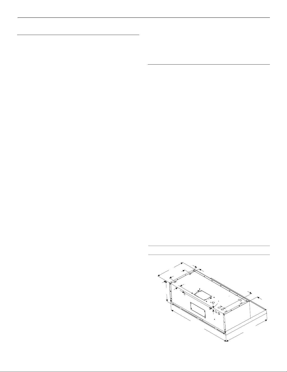
Product Dimensions
4
Installation Clearances
A
B
C
D
E
A
C
B
D
D
For the most efficient and quiet operation:
■ Use no more than three 90° elbows.
■ Make sure there is a minimum of 24" (61 cm) of straight
vent between the elbows if more than 1 elbow is used.
■ Do not install 2 elbows together.
■ Use clamps to seal all joints in the vent system.
■ The vent system must have a damper. If roof or wall cap has
a damper, do not use damper supplied with the range hood.
■ Use caulking to seal exterior wall or roof opening around
the cap.
Cold Weather Installations
An additional back draft damper should be installed to minimize
backward cold air flow and a thermal break should be installed to
minimize conduction of outside temperatures as part of the vent
system. The damper should be on the cold air side of the thermal
break.
The break should be as close as possible to where the vent
system enters the heated portion of the house.
Makeup Air
Local building codes may require the use of makeup air systems
when using ventilation systems greater than specified CFM of
air movement. The specified CFM varies from locale to locale.
Consult your HVAC professional for specific requirements in
your area.
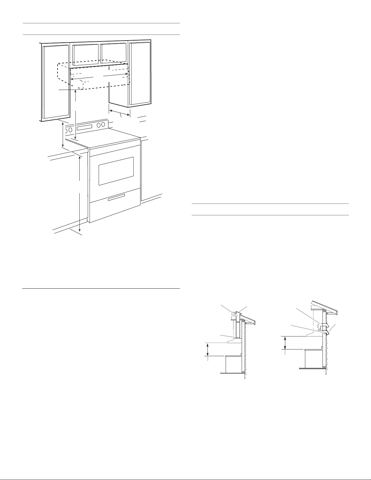
A. 18" (45.7 cm) min. clearance - upper cabinet to countertop
B. 24" (61.0 cm) min. for electric cooking surfaces
27" (68.6 cm) min. for gas cooking surfaces
30" (76.2 cm) suggested max. - bottom of range hood
to cooking surface
C. 30" (76.2 cm) or 36" (91.4 cm) min. cabinet opening width
D. 12" (30.5 cm) min. cabinet depth
E. 36" (91.4 cm) base cabinet height
Venting Requirements
(Vented Models Only)
■ Vent system must terminate to the outdoors except for
non-vented (recirculating) installations.
■ Do not terminate the vent system in an attic or other
enclosed area.
■ Do not use a 4" (10.2 cm) laundry-type wall cap.
■ Use a 6" (15.2 cm) round metal vent or a 3¹⁄₄" x 10" (8.3
x 25.4 cm) rectangular metal vent. Rigid metal vent is
recommended. Plastic or metal foil vent is not recommended.
■ The length of vent system and number of elbows should
be kept to a minimum to provide efficient performance.
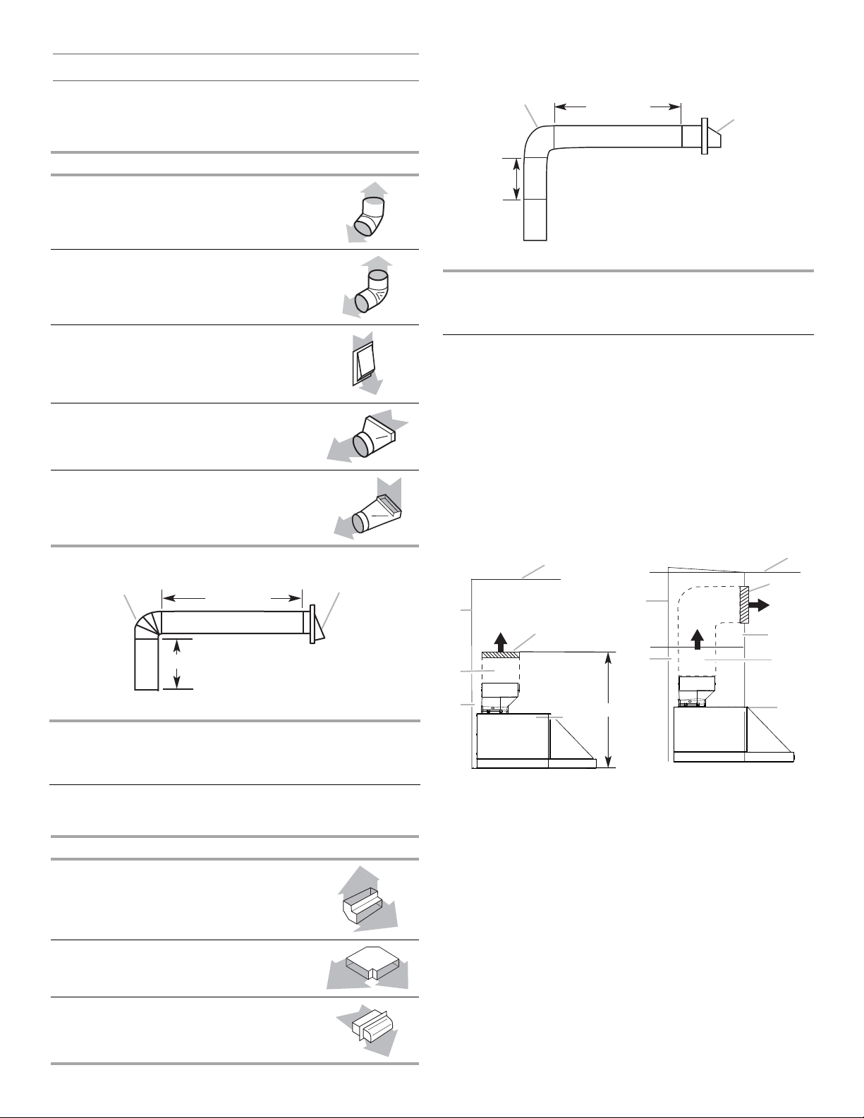
Venting Methods
The vent system for venting out of the top of range hood can
be terminated either through the roof or wall. Use a 6" (15.2 cm)
round vent. The vent system for venting out the rear of the range
hood must be terminated through the wall. Use a 3¹⁄₄" x 10" (8.3
x 25.4 cm) rectangular vent. For rear venting the Damper
Assembly/Motor Mounting Bracket Kit is required. See
“Assistance or Service” section to order.
NOTE: Flexible vent is not recommended. Flexible vent creates
back pressure and air turbulence that gently reduces
performance.
Roof Venting Wall Venting
A
B
C
A. 6" (15.2 cm) round vent
through roof
B. Round vent: 6" (15.2 cm)
diameter transition piece.
C. 24" (61.0 cm) - 30" (76.2 cm)
above electric cooking surface
27" (68.6 cm) - 30" (76.2 cm)
above gas cooking surface
D. Roof cap
A. 6" (15.2 cm) round vent
through the wall
B. 3¹⁄₄" x 10" (8.3 x 25.4 cm)
through the wall (purchased
separately)
C. 24" (61.0 cm) - 30" (76.2 cm)
above electric cooking surface
27" (68.6 cm) - 30" (76.2 cm)
above gas cooking surface
D. Wall cap
5
Calculating Vent System Length
Wall cap
90˚ elbow
2 ft (0.6 m)
6 ft (1.8 m)
Wall cap
3
¹⁄₄" x 10"
(8.3 x 25.4 cm)
elbow
2 ft
(0.6 m)
6 ft (1.8 m)
A
B
D
E
F
G
H
A
B
C
D
E
F
G
To calculate the length of the system you need, add the
equivalent feet (meters) for each vent piece used in the system.
6" (15.2 cm) Round Vent System
Vent Piece Round
Example vent system
45° elbow
90° elbow
6" (15.2 cm) wall cap
3¹⁄₄" x 10" (8.3 cm x 25.4 cm)
to 6" (15.2 cm)
3¹⁄₄" x 10" (8.3 cm x 25.4 cm)
to 6" (15.2 cm) 90° elbow
Example vent system
2.5 ft
(0.8 m)
5.0 ft
(1.5 m)
0.0 ft
(0.0 m)
4.5 ft
(1.4 m)
5.0 ft
(1.5 m)
Maximum Recommended Length = 35 ft (10.7 m)
1 - 90° elbow = 5.0 ft (1.5 m)
8 ft (2.4 m) straight = 8.0 ft (2.4 m)
1 - wall cap = 0.0 ft (0.0 m)
Length of system = 13.0 ft (3.9 m)
Non-Vented (recirculating) Installations Through the Soffit/
Cabinet
If it is not possible to vent cooking fumes and vapors to the
outside, the range hood can be used in the non-vented
(recirculating) version, using a recirculation kit. The recirculation
kit Part Number is W10490330. See “Assistance or Service”
section to order.
For non-vented (recirculating) installations only, the range hood
can be vented indoors through the top of the cabinet or soffit.
Through Cabinet Through Soffit
Maximum Recommended Length = 50 ft (15.2 m)
1 - 90° elbow = 5.0 ft (1.5 m)
1 - wall cap = 0.0 ft (0.0 m)
8 ft (2.4 m) straight = 8.0 ft (2.4 m)
Length of 7" (17.8 cm) system = 13.0 ft (3.9 m)
3¹⁄₄" x 10" (8.3 cm x 25.4 cm) Vent System
Vent Piece
3¹⁄₄" x 10" (8.3 cm x 25.4 cm)
90° elbow
3¹⁄₄" x 10" (8.3 cm x 25.4 cm)
flat elbow
3¹⁄₄" x 10" (8.3 cm x 25.4 cm)
wall cap
6
5.0 ft
(1.5 m)
12.0 ft
(3.7 m)
0.0 ft
(0.0 m)
A. Ceiling
B. Vent cover
C. Soffit
D. 6" (15.2 cm) vent
E. Range hood
F. Cabinet
G. Wall
H. 17" (43.2 cm) min. vent cover
height
NOTE: 12" (30.5 cm) high cabinets without a soffit may allow
the 6" (15.2 cm) vent and vent cover to be seen.
Electrical Requirements
WARNING
Excessive Weight Hazard
Use two or more people to move and install
range hood.
Failure to do so can result in back or other injury.
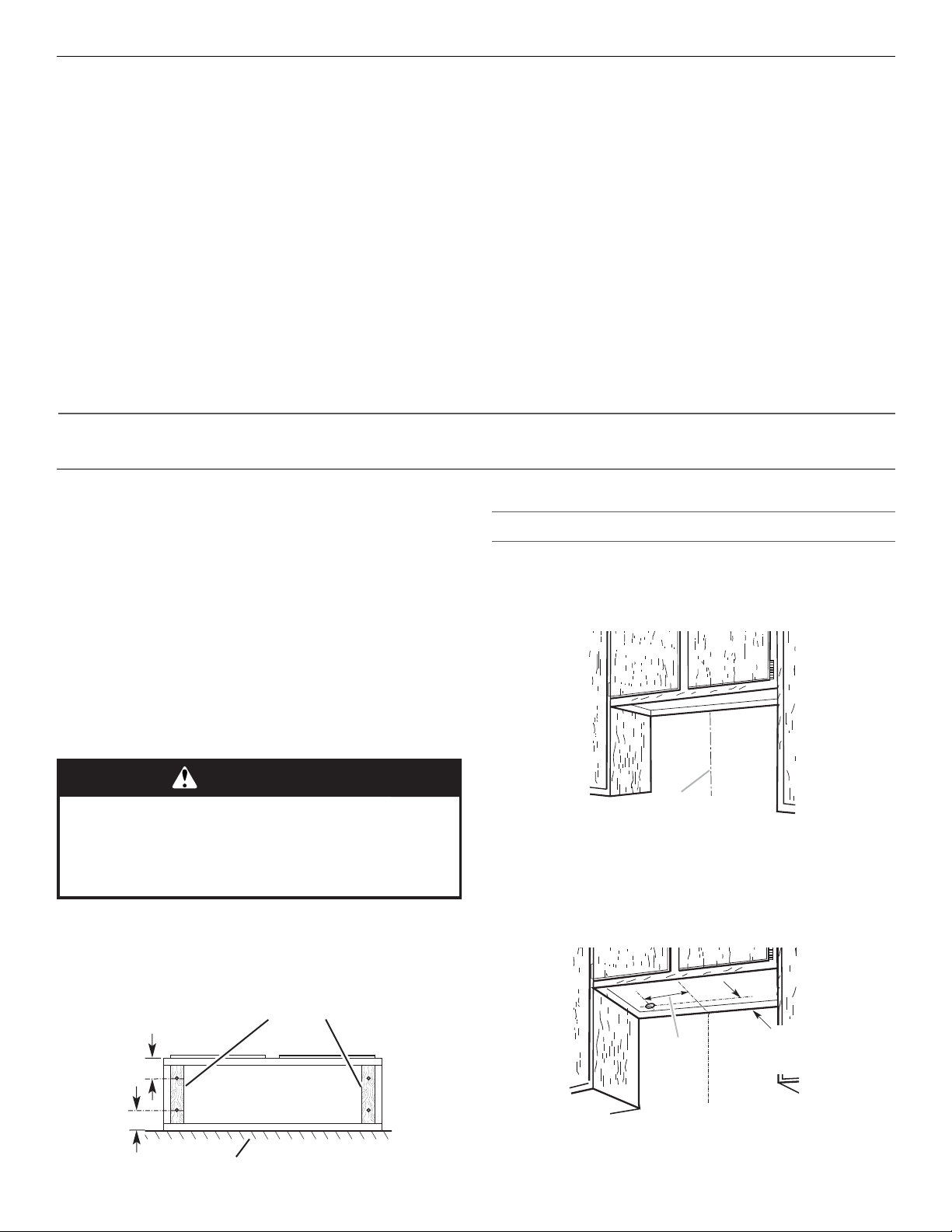
Cabinet
bottom
Wall
3" (7.6 cm)
Wood filler strips
(recessed cabinet
bottoms only)
3" (7.6 cm)
A
Centerline
2" (5.1 cm)
from wall,
not cabinet
frame
A
Observe all governing codes and ordinances.
Ensure that the electrical installation is adequate and in
conformance with National Electrical Code, ANSI/NFPA 70 (latest
edition), or CSA Standards C22.1-94, Canadian Electrical Code,
Part 1 and C22.2 No. 0-M91 (latest edition) and all local codes
and ordinances.
If codes permit and a separate ground wire is used, it is
recommended that a qualified electrician determine that the
ground path is adequate.
A copy of the above code standards can be obtained from:
National Fire Protection Association
1 Batterymarch Park
Quincy, MA 02169-7471
CSA International
8501 East Pleasant Valley Road
Cleveland, OH 44131-5575
■ A 120 volt, 60 Hz., AC only, 15-amp, fused electrical circuit
is required.
INSTALLATION INSTRUCTIONS
Prepare Location
NOTE: For vented installations, it is recommended that the
vent system be installed before the hood is installed.
Before making cutouts, make sure there is proper clearance
within the ceiling or wall for exhaust vent.
NOTE: The exhaust adapter/damper can be installed up to
1" (2.5 cm) on either side of the hood center to accommodate
off-center ductwork.
1. Disconnect power.
2. Determine which venting method to use: roof or wall.
NOTE: For rear venting a Damper Assembly/Motor Mounting
Bracket Kit must be used. See “Assistance or Service” section
to order.
3. Select a flat surface for assembling the range hood.
Place covering over that surface.
■ If the house has aluminum wiring, follow the procedure
below:
1.
Connect a section of solid copper wire to the pigtail leads.
2. Connect the aluminum wiring to the added section
of copper wire using special connectors and/or tools
designed and UL listed for joining copper to aluminum.
Follow the electrical connector manufacturer's recommended
procedure. Aluminum/copper connection must conform with
local codes and industry accepted wiring practices.
■ Wire sizes and connections must conform with the rating
of the appliance as specified on the model/serial/rating plate.
The model/serial/rating plate is located behind the left filter
on the rear wall of the range hood.
■ Wire sizes must conform to the requirements of the National
Electrical Code, ANSI/NFPA 70 (latest edition), or CSA
Standards C22. 1-94, Canadian Electrical Code, Part 1
and C22.2 No. 0-M91 (latest edition) and all local codes
and ordinances.
Determine Wiring Hole Location
Cut only one 1¹⁄₄" (3.2 cm) diameter wiring access hole.
See Step 2 for wiring hole location instructions.
1. Determine and clearly mark a vertical centerline on the wall
and cabinet in the area the vent opening will be made.
4. Using 2 or more people, lift the range hood and set it upside
down onto covered surface.
5. If cabinet has recessed bottom, add wood filler strips on each
side. Install screws to attach filler strips in locations shown.
A. Centerline
2. To wire through top:
Mark a line distance “A” from the left of the centerline on
the underside of the cabinet. Mark the point on this line that
is 2" (5.1 cm) from back wall. Drill a 1¼" (3.2 cm) diameter
hole through the cabinet at this point.
A. 12" (30.5 cm) for 30" (76.2 cm) models
12¼" (31.1 cm) for 36" (91.4 cm) models
7
3. To wire through wall:
Centerline
1" (2.5 cm)
A
2¾"
6¾"
Cabinet
front
(7.0 cm)
(17.1 cm)
5¹⁄₄"
(13.3 cm)
Centerline
5¹⁄₄"
(13.3 cm)
4¹/₄"
(10.8 cm)
4¹/₄"
(10.8 cm)
*7"
(17.8 cm)
*From wall, not cabinet frame
*¹⁄₂" (1.3 cm)
Circular vent opening
Cabinet
cutouts
*From wall, not
cabinet frame
*5"
(12.7 cm)
A
B
Mark a line distance “A” from the left of the centerline on
the wall. Mark the point on this line that is 1" (2.5 cm) from
the bottom of the cabinet. Drill a 1¹⁄₄" (3.2 cm) diameter hole
through the rear wall at this point.
A. 12" (30.5 cm) for 30" (76.2 cm) models
12¼" (31.1 cm) for 36" (91.4 cm) models
Style 1 - Cut Openings for 3¼" x 10" (8.3 cm x 25.4 cm)
Rectangular Vent System
Wall Venting
To make a 4" x 10½" (10.2 cm x 26.7 cm) rectangle in the wall:
1. Make 2 lines by measuring 2³⁄₄" (7.0 cm) and 6³⁄₄" (17.1 cm)
down from underside of cabinet and mark on the centerline
on the back wall.
2. Mark lines 5¼" (13.3 cm) to the right and left of the centerline
on the wall.
3. Use saber or keyhole saw to cut a rectangular opening in
the wall for the vent.
To make a circular vent opening on the underside of the
cabinet top:
1. Mark a centerline on the underside of the top of cabinet.
2. Mark a line 3³⁄₄" (9.5 cm) from the back wall on the underside
of the top of cabinet.
3. Use a compass or a circle template to draw a 6¼" (15.2 cm)
circle.
4. Use saber or keyhole saw to cut the circular vent opening.
Non-Vented (recirculating) Installation Through the
Soffit/Cabinet
Measure and mark the centerline of the cabinet to the soffit
above.
Measure from the bottom of the cabinet to the centerline
of the where the vent will come through the soffit. Mark the
location and use a saber saw or keyhole saw to cut a 5¾"
(14.6 cm) hole for the vent cover.
Style 2 - Cut Openings for Rectangular to 6" (15.2 cm)
Round Vent Transition
Roof Venting and non-vented (recirculating)
To make a 6½" x 8½" (16.5 cm x 26.7 cm) rectangular cutout
on the underside of cabinet bottom:
1. Mark lines ½" (1.3 cm) and 7" (17.8 cm) from the back wall on
the centerline of the underside of cabinet.
2. Mark lines 4¼" (10.8 cm) to the right and left of the centerline
on the underside of cabinet.
3.
Use saber or keyhole saw to cut a rectangular opening for vent.
8
A. Vent cover
B. Centerline
Install Vent System
1. Install vent through the vent opening in cabinet or wall.
Complete venting system according to the selected venting
method. See “Venting Requirements” section.
2. Use caulking to seal exterior wall or roof opening around the
cap.
Install In-Line Smart Kit - Optional
NOTE: Your range hood can work with either an internal or an in-
line (external) blower motor system. An optional In-Line Smart Kit
(purchased separately) allows the blower motor that comes with
this range hood to be installed in a location other than inside the
range hood cavity.
CAUTION: To reduce the risk of fire and electric shock, install this
range hood only with the In-Line Smart Kit manufactured by
Whirlpool, Part Number W10692945.
For installation see the In-Line Smart Kit installation instructions.
See the “Assistance or Service” section to order.
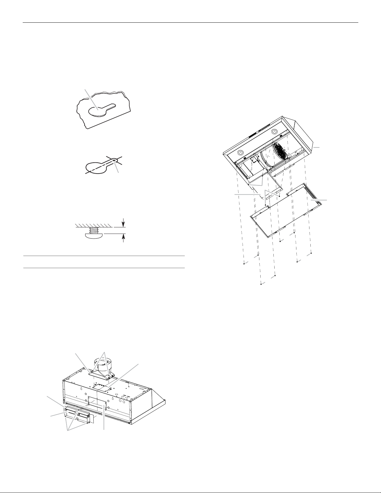
Install Range Hood
A
A
¹⁄₄"
(6.4 mm)
A
B
C
D
F
G
E
B
A
C
D
E
E
E
E
1.
Remove the grease filters. See the “Range Hood Care” section.
2. Remove foam shipping pad from behind the blower motor.
3. Lift the range hood up under cabinet and determine final
location by centering beneath cabinet. Mark on the underside
of cabinet the location of the 4 keyhole mounting slots on the
range hood. Set range hood aside on a covered surface.
A. Keyhole slot
4. Use ¹⁄₈" (3 mm) drill bit and drill 4 pilot holes as shown.
A. Drill pilot hole
5. Install the 4 - 4.5 x 13 mm mounting screws in pilot holes.
Leave about ¹⁄₄" (6.4 mm) space between screw heads
and cabinet to slide range hood into place.
Rear Vent Connector Installation
NOTE: For rear venting, the blower motor position must be
changed. It will need the rear motor mounting bracket that
is included with the 3¹⁄₄" x 10" (8.3 cm x 25.4 cm) Damper
Assembly/Motor Mounting Bracket Kit that must be purchased
separately. See “Assistance or Service” section to order.
1. Remove the rear vent knockout.
2. Place range hood on its back.
3. Using a T10 Torx® adapter, remove the 8 screws holding
the bottom panel assembly in place. Remove the bottom
panel assembly and set it aside.
Vent Connector Installation
Determine whether the range hood will be installed using either
a top or rear vent connection.
Top Vent Connector Installation
1. Remove the top vent knockout.
2. Attach the round vent transition damper using 2 vent
transition mounting screws.
3. Remove tape from damper flap
NOTE: If the wall cap is directly behind the vent connector,
the dampers in the connector and wall cap must not interfere.
Remove the vent connector damper if they interfere.
A. Blower motor cover plate
B. Blower motor cover plate
mounting screws (4)
C. Back of range hood
4. Disconnect the blower motor electrical connector from
the electrical box connector.
5. Using a T10 Torx
®
adapter, remove the 4 screws from the
motor cover plate. Remove the motor cover plate and set
D. Bottom panels assembly
E. Bottom panels assembly
mounting screws
it aside.
A. Top round vent transition
B. Top round vent transition
mounting screws (2)
C. Top vent knockout
D. Rear vent knockout
E. Rear rectangular transition
knockout mounting screws (3)
F. Hi n ge pi n
G. Rear rectangular vent transition
9
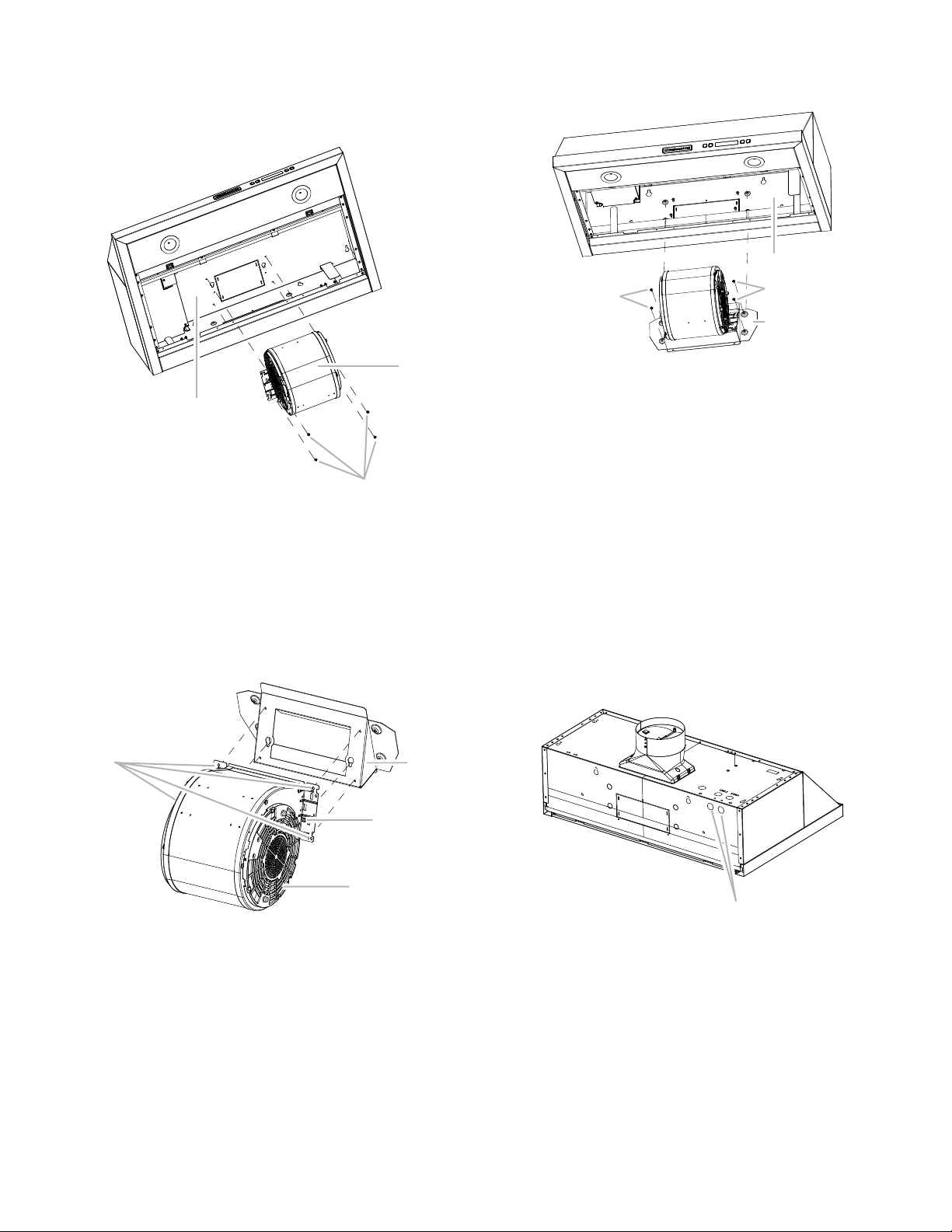
6. Remove the rear insulation panel and set it aside.
C
A
B
C
B
A
D
B
B
C
A
A
7. Using a T20® Tor x® adapter, remove the 4 screws holding
the blower motor in place. Push up on the blower motor to
disengage the tabs from range hood cavity back. Remove
the blower motor and set it aside.
A. Range hood canopy (inside top)
B. Blower motor
C. Blower motor mounting screws
8. Install the blower motor onto the rear motor mounting bracket
(included with the 3¹⁄₄" x 10" (8.3 cm x 25.4 cm) Damper
Assembly/Motor Mounting Bracket Kit; see “Accessories or
Service” section to order). Engage the motor mounting tabs
into keyhole slots in rear mounting bracket and push down to
secure. Install the 4 screws removed in Step 7 and tighten to
secure motor bracket.
9. Install the blower motor assembly into the range hood and
secure with the 4 screws supplied with rear motor mounting
bracket assembly.
A. Range hood canopy (inside top)
B. Blower motor mounting screws
C. Rear blower motor mounting bracket assembly
10. Reconnect blower motor electrical connector to the electrical
box connector.
11. Reinstall the rear insulating panel.
12. Reinstall the motor cover plate to range hood using the
4 screws removed in Step 3.
13. Reinstall bottom panels assembly to range hood using
the 8 screws removed in Step 2.
14. Attach the 3¹⁄₄" x 10" (8.3 cm x 25.4 cm) rectangular vent
damper (purchased separately) using 3 vent transition
mounting screws. Make sure the vent damper pivot is nearest
to the top back edge of the range hood. See vent connector
illustration in “Top Vent Connector Installation” in this section.
Install Range Hood to Cabinet
1.
Remove the round knockout from the top or back of the range
hood (depending on your wiring location) for the wiring strain
relief and install a
¹⁄₂
" UL listed or CSA approved strain relief.
A. Rear motor mounting bracket
B. Motor mounting tabs (2)
C. Blower motor
D. Blower motor mounting screws (4)
A. Round knockout
2. Using 2 people, lift range hood into final location. Feed
enough electrical wire through the strain relief to make
connections in the terminal box. Tighten the strain relief
screws.
3. Position the range hood so that the large end of the keyhole
slots are over the mounting screws. Then push the hood
toward the wall so that the screws are in the neck of the slots.
10
The hood should be against the wall. Tighten the mounting
screws, making sure mounting screws are in the narrow neck
of the slots.
4. Check that damper, if used, rotates up and down freely.
5. Connect ventwork to hood. Seal joints with clamps to make
secure and airtight.
 Loading...