

KitchenAid KSSS48QKX02, KBLC36FKS01, KSSC42QMS02 Installation Guide

Kitchen_kid ®
INSTALLATION GUIDE
IMPORTANT: READ AND SAVE THESE INSTRUCTIONS. INSTALLATION REQUIRES 2 OR MORE PEOPLE.
MANUAL DE INSTALACION
IMPORTANTE: LEA Y GUARDE ESTAS INSTRUCCIONES. LA INSTALACION REQUIERE DE 2 O MAS PERSONAS.
GUIDE D'INSTALLATION
_:__,i_ _/_!;!_
IMPORTANT : LIRE ET CONSERVER CES INSTRUCTIONS.
L'INSTALLATION N]_CESSITE L'INTERVENTION DE 2 PERSONNES OU PLUS.
Table of Contents/indite/Table des matieres ................................ 2
2266877

TABLE OF CONTENTS TABLE DES MATIERES
REFRIGERATOR SAFETY .......................................................... 3
INSTALLATION REQUIREMENTS ................................................ 4
Tools and Parts ............................................................................ 4
Product Dimensions ..................................................................... 4
Location Requirements ................................................................ 6
Electrical Requirements ............................................................... 7
Water Supply Requirements ........................................................ 7
Tipping Radius ............................................................................. 7
Door Swing Dimensions ............................................................... 8
Factory Panels and Kits ............................................................... 9
Custom Top Grille and Door Panels .......................................... 10
Custom Side Panels ................................................................... 12
INSTALLATION INSTRUCTIONS ................................................ 13
Unpack Refrigerator ................................................................... 13
Reduce Tipping Radius .............................................................. 13
Install Anti-Tip Boards ................................................................ 14
Install New Water Line ............................................................... 14
Water System Connection ......................................................... 15
Plug in Refrigerator .................................................................... 15
Move Refrigerator to Final Position ........................................... 16
Lower Leveling Legs .................................................................. 16
Install Door Panels ..................................................................... 16
Level Refrigerator ....................................................................... 16
Adjust Doors ............................................................................... 17
Install Decorative Top Panel ...................................................... 18
Install Side Panel ........................................................................ 19
Install Base Grille ........................................................................ 19
Complete Installation ................................................................. 19
SI_CURITI_ DU RI_FRIGI_RATEUR ........................................... 38
EXIGENCES D'INSTALLATION ................................................... 39
Outillage et pieces necessaires ................................................. 39
Dimensions du produit ............................................................... 39
Exigences d'emplacement ......................................................... 41
Specifications electriques .......................................................... 42
Specifications de I'alimentation en eau ..................................... 42
Rayon de basculement .............................................................. 42
Dimensions pour le pivotement des portes ............................... 43
Ensembles de panneaux d'origine ............................................. 44
Panneaux personnalises de la grille superieure et de porte ......45
Panneaux lateraux personnalises .............................................. 47
INSTRUCTIONS D'INSTALLATION ............................................. 48
D_ballage du refrigerateur .......................................................... 48
Reduction du rayon de basculement ......................................... 48
Installation de planches anti-basculement ................................ 49
Installation d'une nouvelle canalisation d'eau ........................... 50
Raccordement de la canalisation d'eau .................................... 50
Brancher le rdrigerateur ............................................................. 51
D_placement du refrigerateur a I'emplacement final ................. 51
Deploiement des pieds de nivellement ...................................... 51
Installation des panneaux de porte ............................................ 51
Nivellement du refrigerateur ....................................................... 52
Ajustement des portes ............................................................... 52
Installation du panneau decoratif superieur ............................... 54
Installation du panneau lateral ................................................... 54
Installation de la grille de la base ............................................... 55
Achever I'installation .................................................................. 55
p
INDICE
SEGURIDAD DEL REFRIGERADOR ........................................ 20
REQUlSITOS DE INSTALACION ................................................. 21
Piezas y herramientas ................................................................ 21
Medidas del producto ................................................................ 21
Requisitos de ubicaci6n ............................................................. 23
Requisitos electricos .................................................................. 24
Requisitos de suministro de agua ............................................. 24
Arco de vuelco ........................................................................... 25
Medidas de oscilaci6n de las puertas ....................................... 25
Paneles y juegos de fabrica ....................................................... 26
Paneles a la medida para la rejilla superior y las puertas .......... 27
Paneles laterales a la medida .................................................... 29
INSTRUCCIONES DE INSTALACION ......................................... 30
C6mo desempacar su refrigerador ............................................ 30
C6mo reducir el arco de vuelco ................................................. 31
C6mo instalar los tableros anti-vuelco ...................................... 31
Instalaci6n de una tuberia de agua nueva ................................. 32
C6mo conectar el sistema de agua ........................................... 32
C6mo enchufar el refrigerador ................................................... 33
Ubicaci6n final del refrigerador .................................................. 33
Patas niveladoras inferiores ....................................................... 34
C6mo instalar los paneles de la puerta ..................................... 34
C6mo nivelar el refrigerador ....................................................... 34
C6mo ajustar las puertas ........................................................... 35
C6mo instalar el panel decorative superior ............................... 36
C6mo instalar el panel lateral ..................................................... 37
C6mo instalar la rejilla de la base .............................................. 37
C6mo terminar la instalaci6n ..................................................... 37
REFRIGERATOR SAFETY
Your safety and the safety of others are very important.
We have provided many important safety messages in this manual and on your appliance. Always read and obey all
safety messages.
This symbol alerts you to potential hazards that can kill or hurt you and others.
All safety messages will follow the safety alert symbol and either the word "DANGER" or
This is the safety alert symbol.
"WARNING." These words mean:
You can be killed or seriously injured if you don't
immediately follow instructions.
You can be killed or seriously injured ifyou don't
follow instructions.
All safety messages will tell you what the potential hazard is, tell you how to reduce the chance of injury, and tell you
what can happen if the instructions are not followed.
Tip Over Hazard
Refrigerator is top heavy and tips easily when
not completely installed.
Keep doors taped closed until refrigerator is
completely installed.
Use two or more people to move and install
refrigerator.
Failure to do so can result in death or
serious injury.
INSTALLATION
REQUIREMENTS
IMPORTANT:
Observe all governing codes and ordinances.
Installer: Leave Installation Instructions with the homeowner.
Homeowner: Keep Installation Instructions for future
reference. Save these Installation Instructions for the local
electrical inspector's use.
• Keep cardboard shipping piece or plywood under refrigerator
until it is installed in the operating position.
• Comply with installation specifications and dimensions.
• Remove any moldings or decorative panels that prevent the
refrigerator from being serviced.
• Contact a qualified electrical installer.
• Order factory panels, make custom panels, or consult a
qualified cabinetmaker or carpenter to make panels.
Tools needed:
Make sure that you have the tools necessary for proper
installation:
• Hand drill or electric drill
(properly grounded)
• Drill bits
• Two adjustable wrenches
• Phillips screwdriver
Parts needed:
Your refrigerator dealer has a kit available with a 1/4in. (6.35
mm) saddle-type shutoff valve, a union, and copper tubing.
• 1/4in. (6.35 mm) copper tubing with shutoff valve
• 1/4in. (6.35 mm) compression fitting
• 6 - #8 x 3 in. (7.6 cm) wood screws (longer screws may be
needed)
• lor2-2in, x4in. x 32in.(5cmx10cmx81cm)wood
board(s)
• Custom panels (provided by homeowner)
• 7A6in. and 1/2in. open-end
wrenches
• ¼in. nut driver
• %2 in. Allen wrench
• sA6in, socket wrench
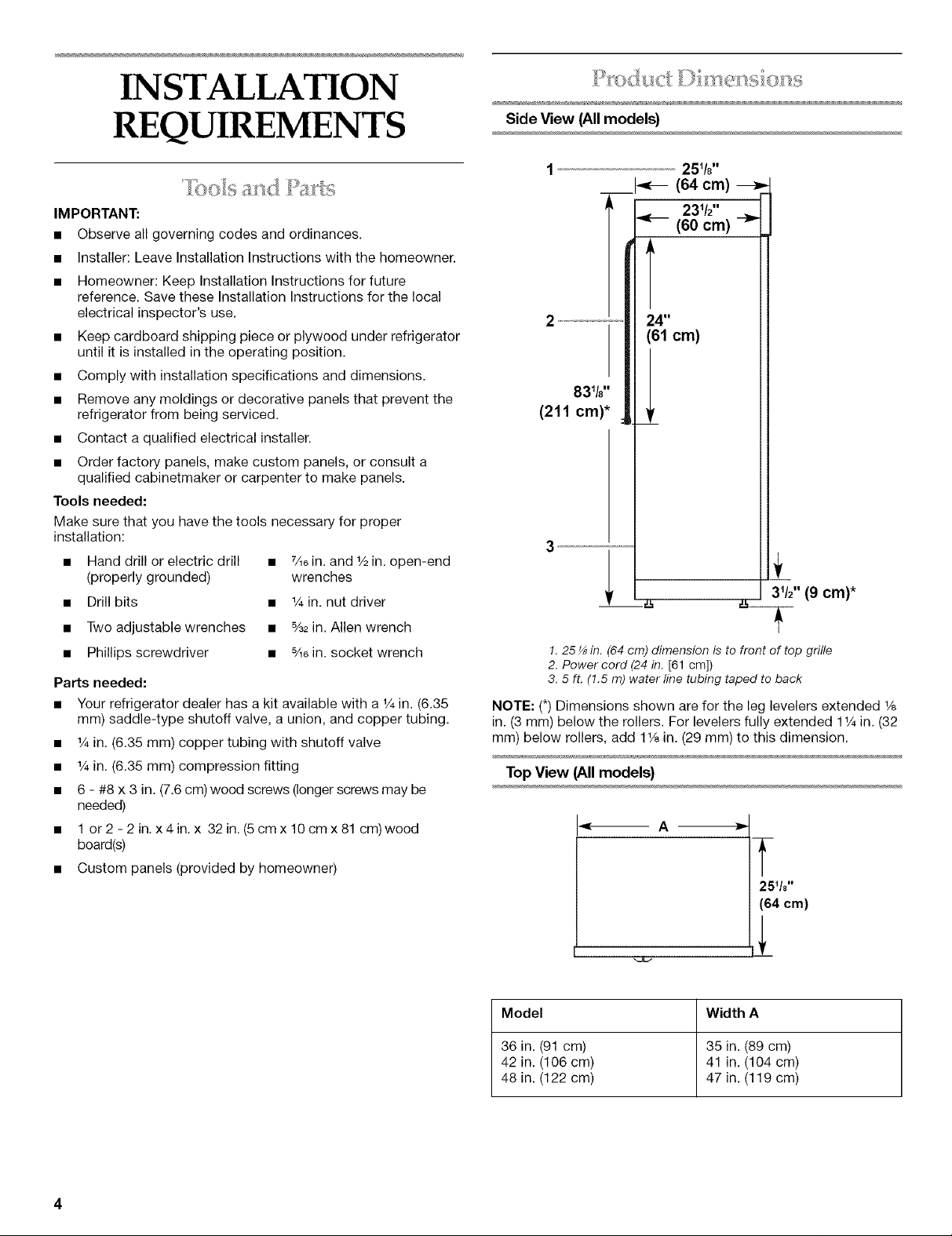
Side View (All models}
251/¢'
__ _ (64 cm)
231/2''
(60 cm) --_
T
24"
(61 cm)
31/2'' (9 cm)*
1,25 _ in. (64 cm) dimension is to front of top grille
2. Power cord (24 in. [61 cm])
3, 5 ft, (!.5 m) waterline tubing taped to back
NOTE: (*) Dimensions shown are for the leg levelers extended 1/8
in. (3 mm) below the rollers. For levelers fully extended 11/4in. (32
mm) below rollers, add 11/8in. (29 mm) to this dimension.
Top View (All models}
A
T
25q8"
(64 cm)
Model Width A
36 in. (91 cm) 35 in. (89 cm)
42 in. (106 cm) 41 in. (104 cm)
48 in. (122 cm) 47 in. (119 cm)
4
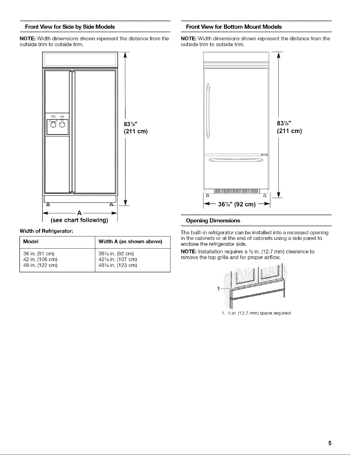
Front View for Side by Side Models
Front View for Bottom Mount Models
NOTE: Width dimensions shown represent the distance from the
outside trim to outside trim.
__
831/8''
(211 cm)
A
(see chart following)
Width of Refrigerator:
Model Width A (as shown above)
36 in. (91 cm) 36V4in. (92 cm)
42 in. (106 cm) 42V4in. (107 cm)
48 in. (122 cm) 48V4in. (123 cm)
NOTE: Width dimensions shown represent the distance from the
outside trim to outside trim.
83_/8''
(211 cm)
36_/4'' (92 cm)
Opening Dimensions
The built-in refrigerator can be installed into a recessed opening
in the cabinets or at the end of cabinets using a side panel to
enclose the refrigerator side.
NOTE: Installation requires a _/_in. (12.7 mm) clearance to
remove the top grille and for proper airflow.
_ L .........
!. ½in. (12.7 mm)space required
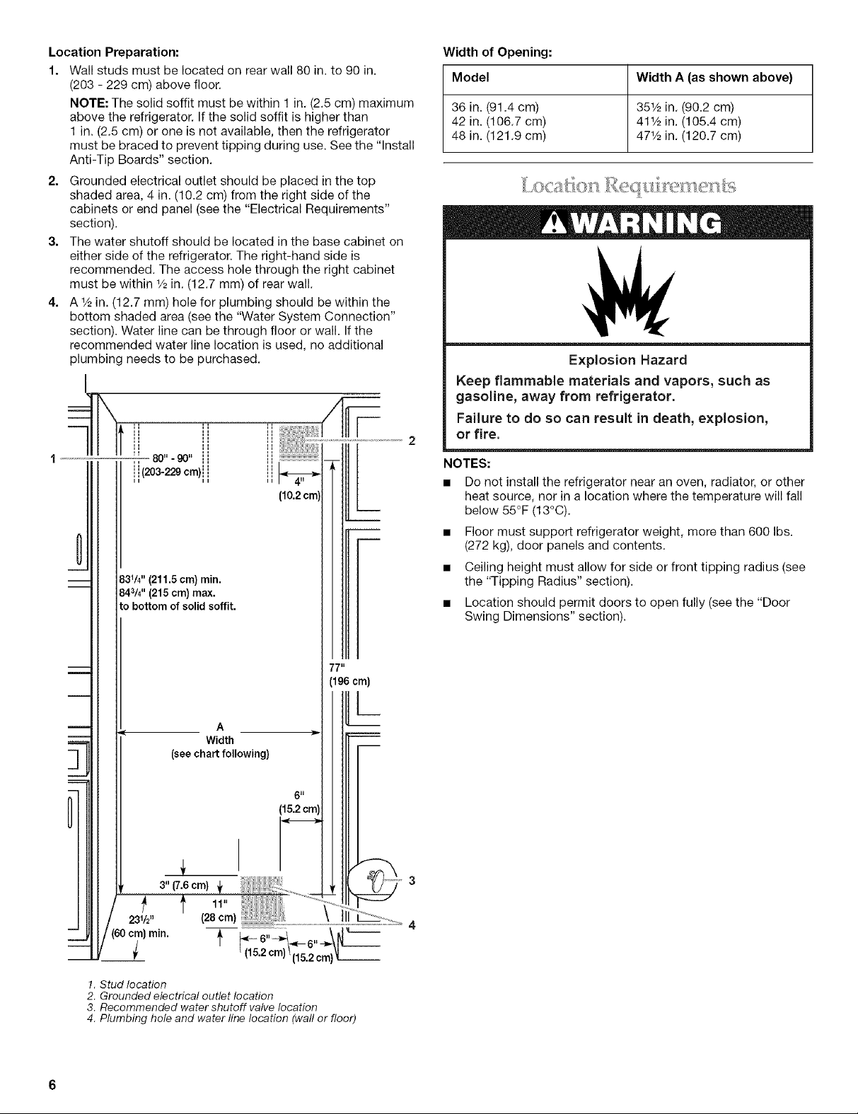
Location Preparation:
1. Wall studs must be located on rear wall 80 in. to 90 in.
(203 - 229 cm) above floor.
NOTE: The solid soffit must be within 1 in. (2.5 cm) maximum
above the refrigerator. If the solid soffit is higher than
1 in. (2.5 cm) or one is not available, then the refrigerator
must be braced to prevent tipping during use. See the "Install
Anti-Tip Boards" section.
2. Grounded electrical outlet should be placed in the top
shaded area, 4 in. (10.2 cm) from the right side of the
cabinets or end panel (see the "Electrical Requirements"
section).
3. The water shutoff should be located in the base cabinet on
either side of the refrigerator. The right-hand side is
recommended. The access hole through the right cabinet
must be within 1/2in. (12.7 mm) of rear wall.
4. A 1/2in. (12.7 mm) hole for plumbing should be within the
bottom shaded area (see the "Water System Connection"
section). Water line can be through floor or wall. If the
recommended water line location is used, no additional
plumbing needs to be purchased.
3W' (211.5 cm) min.
843/4"(215 cm)max.
to bottom of solid soffit.
Width of Opening:
Model Width A (as shown above)
36 in. (91.4 cm) 351/2in. (90.2 cm)
42 in. (106.7 cm) 411/2in. (105.4 cm)
48 in. (121.9 cm) 471/2in. (120.7 cm)
Explosion Hazard
Keep flammable materials and vapors, such as
gasoline, away from refrigerator.
Failure to do so can result in death, explosion,
or fire.
NOTES:
• Do not install the refrigerator near an oven, radiator, or other
heat source, nor in a location where the temperature will fall
below 55°F (13°C).
• Floor must support refrigerator weight, more than 600 Ibs.
(272 kg), door panels and contents.
• Ceiling height must allow for side or front tipping radius (see
the "Tipping Radius" section).
• Location should permit doors to open fully (see the "Door
Swing Dimensions" section).
77 II
(196cm)
A
Width
(see chart following)
5 II
(15.2cm)
1. Stud location
2. Grounded electrical outlet location
3. Recommended water shutoff valve location
4. Plumbing hole and water line location (wall or floor)
L
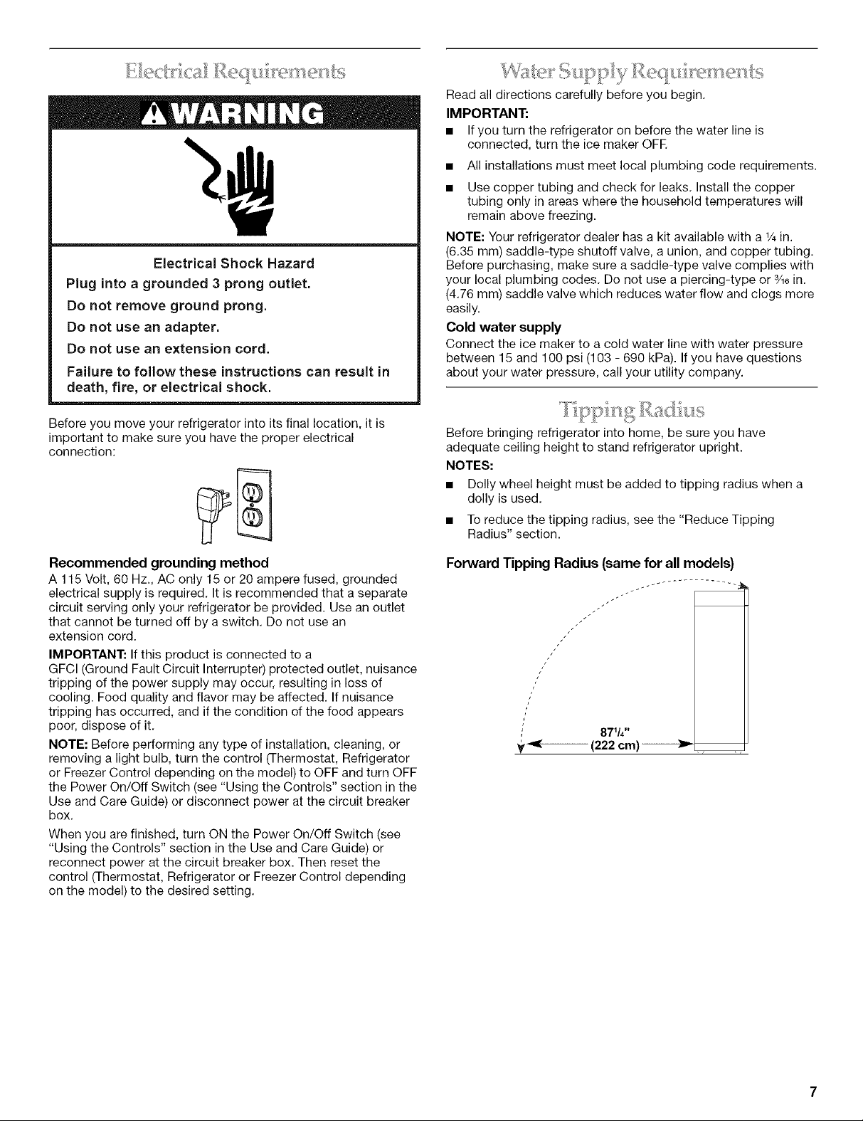
ElectricalShock Hazard
Plug into a grounded 3 prong outlet.
Do not remove ground prong.
Do not use an adapter.
Do not use an extension cord.
Failure to follow these instructions can result in
death, fire, or electrical shock.
Read all directions carefully before you begin.
IMPORTANT:
• If you turn the refrigerator on before the water line is
connected, turn the ice maker OFR
• All installations must meet local plumbing code requirements.
• Use copper tubing and check for leaks. Install the copper
tubing only in areas where the household temperatures will
remain above freezing.
NOTE: Your refrigerator dealer has a kit available with a ¼ in.
(6.35 ram) saddle-type shutoff valve, a union, and copper tubing.
Before purchasing, make sure a saddle-type valve complies with
your local plumbing codes. Do not use a piercing-type or 3/_6in.
(4.76 ram) saddle valve which reduces water flow and clogs more
easily.
Cold water supply
Connect the ice maker to a cold water line with water pressure
between 15 and 100 psi (103 - 690 kPa). If you have questions
about your water pressure, call your utility company.
Before you move your refrigerator into its final location, it is
important to make sure you have the proper electrical
connection:
Recommended grounding method
A 115 Volt, 60 Hz., AC only 15 or 20 ampere fused, grounded
electrical supply is required. It is recommended that a separate
circuit serving only your refrigerator be provided. Use an outlet
that cannot be turned off by a switch. Do not use an
extension cord.
IMPORTANT: If this product is connected to a
GFCI (Ground Fault Circuit Interrupter) protected outlet, nuisance
tripping of the power supply may occur, resulting in loss of
cooling. Food quality and flavor may be affected. If nuisance
tripping has occurred, and if the condition of the food appears
poor, dispose of it.
NOTE: Before performing any type of installation, cleaning, or
removing a light bulb, turn the control (Thermostat, Refrigerator
or Freezer Control depending on the model) to OFF and turn OFF
the Power On/Off Switch (see "Using the Controls" section in the
Use and Care Guide) or disconnect power at the circuit breaker
box.
When you are finished, turn ON the Power On/Off Switch (see
"Using the Controls" section in the Use and Care Guide) or
reconnect power at the circuit breaker box. Then reset the
control (Thermostat, Refrigerator or Freezer Control depending
on the model) to the desired setting,
Before bringing refrigerator into home, be sure you have
adequate ceiling height to stand refrigerator upright.
NOTES:
• Dolly wheel height must be added to tipping radius when a
doily is used.
• To reduce the tipping radius, see the "Reduce Tipping
Radius" section.
Forward Tipping Radius (same for all models)
jJ
/
/'
/
8T/4"
_----- (222 cm) ------_t_,
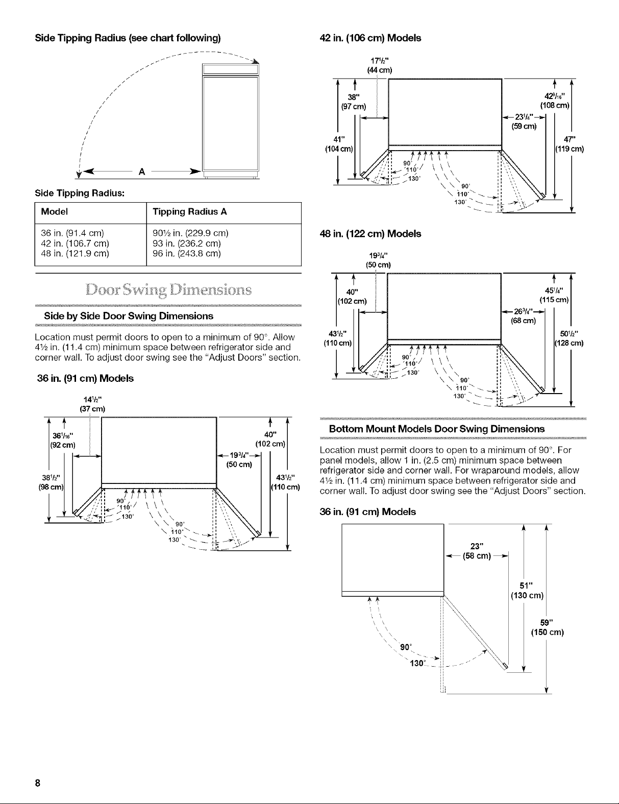
Side Tipping Radius (see chart following)
/
//
v
Side Tipping Radius:
Model Tipping Radius A
42 in. (106 cm) Models
t'
429114'
(108cm)
36 in. (91.4 cm) 901/2in. (229.9 cm)
42 in. (106.7 cm) 93 in. (236.2 cm)
48 in. (121.9 cm) 96 in. (243.8 cm)
Side by Side Door Swing Dimensions
Location must permit doors to open to a minimum of 90°. Allow
41/2in. (11.4 cm) minimum space between refrigerator side and
corner wall. To adjust door swing see the "Adjust Doors" section.
36 in.(91 cm) Models
40"
(102 cm)
48 in. (122 cm) Models
193/4''
(50crn)
43V2"
.,oo)l
Bottom Mount Models Door Swing Dimensions
Location must permit doors to open to a minimum of 90°. For
panel models, allow 1 in. (2.5 cm) minimum space between
refrigerator side and corner wall. For wraparound models, allow
41/2in. (11.4 cm) minimum space between refrigerator side and
corner wall. To adjust door swing see the "Adjust Doors" section.
36 in. (91 cm) Models
23"
(58cm)
(1: Icm)
59"
(150 cm)
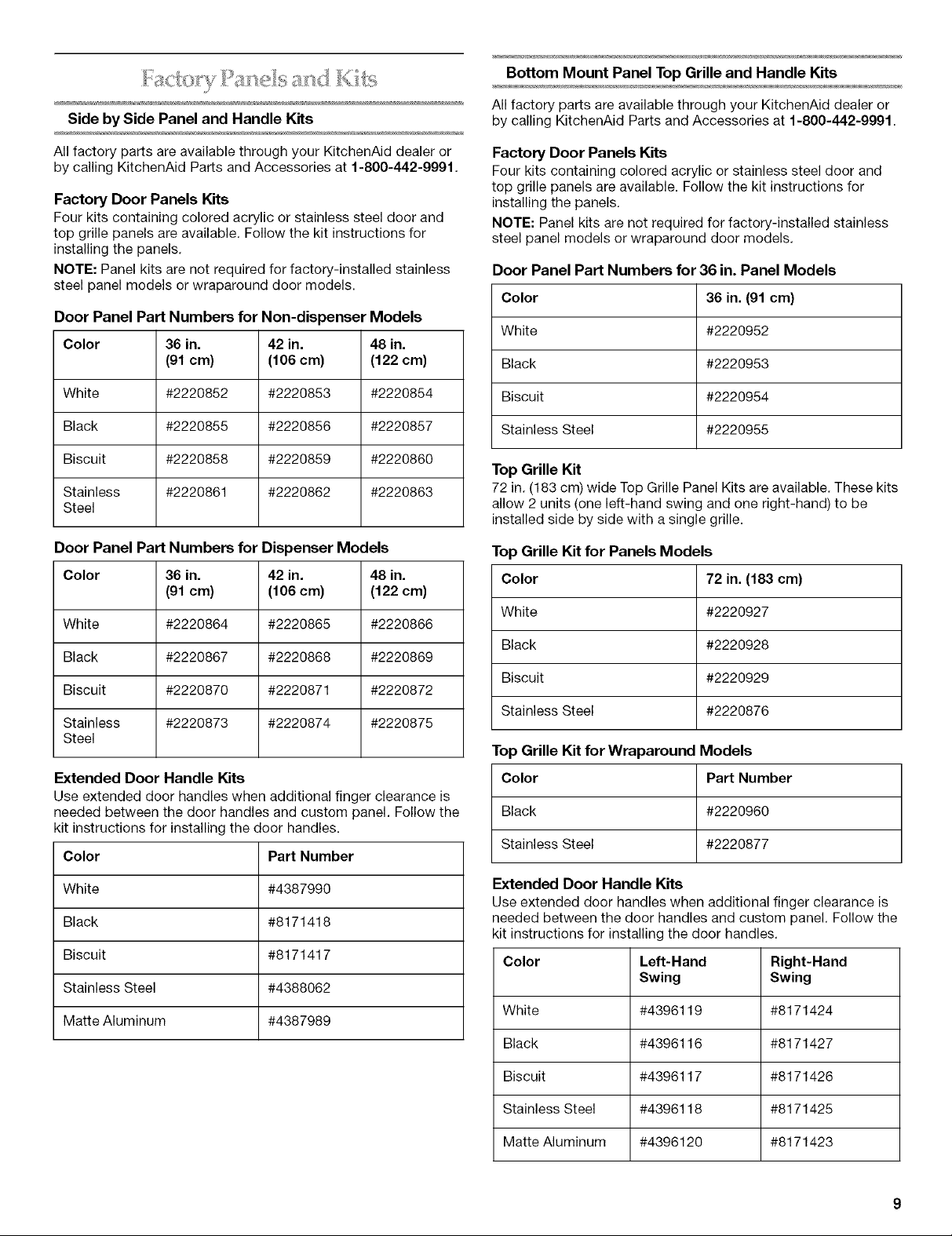
Bottom Mount Panel Top Grille and Handle Kits
SidebySidePanelandHandleKits
All factory parts are available through your KitchenAid dealer or
by calling KitchenAid Parts and Accessories at 1-800-442-9991.
Factory Door Panels Kits
Four kits containing colored acrylic or stainless steel door and
top grille panels are available. Follow the kit instructions for
installing the panels.
NOTE: Panel kits are not required for factory-installed stainless
steel panel models or wraparound door models.
Door Panel Part Numbers for Non-dispenser Models
Color 36 in. 42 in. 48 in.
(91 cm) (106 cm) (122 cm)
White #2220852 #2220853 #2220854
Black #2220855 #2220856 #2220857
Biscuit #2220858 #2220859 #2220860
Stainless #2220861 #2220862 #2220863
Steel
Door Panel Part Numbers for Dispenser Models
Color 36 in. 42 in. 48 in.
(91 cm) (106 cm) (122 cm)
White #2220864 #2220865 #2220866
Black #2220867 #2220868 #2220869
Biscuit #2220870 #2220871 #2220872
Stainless #2220873 #2220874 #2220875
Steel
Extended Door Handle Kits
Use extended door handles when additional finger clearance is
needed between the door handles and custom panel. Follow the
kit instructions for installing the door handles.
Color Part Number
All factory parts are available through your KitchenAid dealer or
by calling KitchenAid Parts and Accessories at 1-800-442-9991.
Factory Door Panels Kits
Four kits containing colored acrylic or stainless steel door and
top grille panels are available. Follow the kit instructions for
installing the panels.
NOTE: Panel kits are not required for factory-installed stainless
steel panel models or wraparound door models.
Door Panel Part Numbers for36in. Panel Models
Color
White
Black
Biscuit
Stainless Steel
36in.(91 cm)
#2220952
#2220953
#2220954
#2220955
Top Grille Kit
72 in. (183 cm) wide Top Grille Panel Kits are available. These kits
allow 2 units (one left-hand swing and one right-hand) to be
installed side by side with a single grille.
Top Grille Kit for Panels Models
Color 72 in. (183 cm)
White #2220927
Black #2220928
Biscuit #2220929
Stainless Steel #2220876
Top Grille Kit for Wraparound Models
Color
Black
Stainless Steel
Part Number
#2220960
#2220877
White #4387990
Black #8171418
Biscuit #8171417
Stainless Steel #4388062
Matte Aluminum #4387989
Extended Door Handle Kits
Use extended door handles when additional finger clearance is
needed between the door handles and custom panel. Follow the
kit instructions for installing the door handles.
Color Left-Hand Right-Hand
Swing Swing
White #4396119 #8171424
Black #4396116 #8171427
Biscuit #4396117 #8171426
Stainless Steel #4396118 #8171425
Matte Aluminum #4396120 #8171423

Ifyouplantoinstallcustomwoodpanels,youwillneedtocreate
thepanelsyourselforconsultaqualifiedcabinetmakeror
carpenter.Seedimensionaldrawingsforpanelspecifications.
IMPORTANT:Panelsweighingmorethanrecommendedmay
causedamagetoyourrefrigerator.
NOTE:Dimensionsshownhavea(_+)1/16in.(1.5mm)tolerance.
Panelsthataremorethan1/4in.(6mm)thickmustberouted.If
panelsarelessthan1/4in.(6mm)thick,installafillerpanel
betweendoorsanddecorativepanels.
Side by Side Custom Top Grille and Door Panels
Door Panels for Dispenser Models
The two freezer panels combined should not weigh more than
30 Ibs. (13.5 kg). The refrigerator panel should not weigh more
than 50 Ibs. (23 kg).
-<-_ B-_
J
237/t¢'
[60cm)
Top Grille Panel
The top panel should not weigh more than 10 Ibs. (4.5 kg).
_(18.4 cm)
Model A
36 in. (91 cm) 353/8in. (90 cm)
42 in. (106 cm) 41% in. (105 cm)
48 in. (122 cm) 47% in. (120 cm)
Door Panels for Non-dispenser Models
The freezer panel should not weigh more than 30 Ibs. (13.5 kg).
The refrigerator panel should not weigh more than 50 Ibs. (23 kg).
_--- A ------_ ,_-_B -_._
707tt¢'
(179cm)
347/_¢'
[87cm)
m
Model A B
36 in. (91 cm) 141/4in. (36 cm) 191/4in. (49 cm)
42 in. (106 cm) 16% in. (43 cm) 223/4in. (58 cm)
48 in. (122 cm) 191/4in. (49 cm) 261/4in. (67 cm)
Bottom Mount Custom Top Grille and Door Panels
Top Grille Panel
Thetop panel should not weigh more than 10 Ibs. (4.5 kg).
353/8''
I'<_ (89.9 cm) _1
Model A B
36 in. (91 cm) 141/4in. (36 cm) 191/4in. (49 cm)
42 in. (106 cm) 163/4in. (43 cm) 223/4in. (58 cm)
48 in. (122 cm) 191/4in. (49 cm) 261/4in. (67 cm)
10
__(18.4 cm)
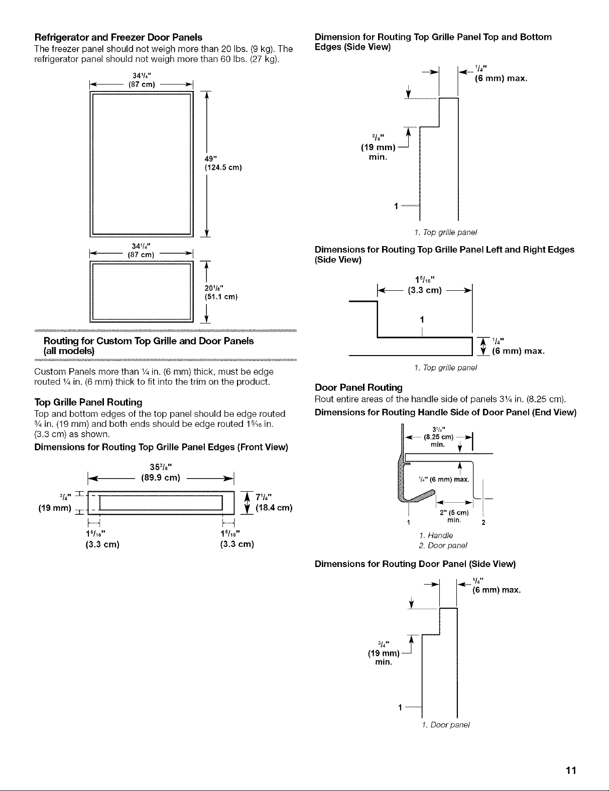
Refrigerator and Freezer Door Panels
The freezer panel should not weigh more than 20 Ibs. (9 kg). The
refrigerator panel should not weigh more than 60 Ibs. (27 kg).
34_/4''
(87 crn) -_
49"
(124.5cm)
34%"
J_ (87 cm) _1
Dimension for Routing Top Grille Panel Top and Bottom
Edges (Side View)
__ (6 mm) max.
3/4,, _-
(19 mm)
min.
1.Topgrille panel
Dimensions for Routing Top Grille Panel Left and Right Edges
(Side View)
_,=[---1/4"
201/8''
(5!.! cm)
Routing for Custom Top Grille and Door Panels
(all models)
Custom Panels more than 1/4in. (6 mm) thick, must be edge
routed 1/4in. (6 mm) thick to fit into the trim on the product.
Top Grille Panel Routing
Top and bottom edges of the top panel should be edge routed
3/4in. (19 mm) and both ends should be edge routed 15/16in.
(3.3 cm) as shown.
Dimensions for Routing Top Grille Panel Edges (Front View)
353/8''
J= (89.9cm) =1
3/411
(,,ram) l lj _(- 7v4''
, , _ (18.4 cm)
F4 F-I
15116'' 1%6"
(3.3 cm) (3.3 cm)
'15/16 II
(3.3 cm) 1
--] !
(6 ram) max.
1. Top grille panel
Door Panel Routing
Rout entire areas of the handle side of panels 31/4in. (8.25 cm).
Dimensions for Routing Handle Side of Door Panel (End View)
31/4 ''
_r, (8.25 cm) _._
mln.
!
1
W'(6 ram)max./
1 min. 2
Dimensions for Routing Door Panel (Side View)
2 5 cm)
1. Handle
2• Door panel
3/4"
(19 mm)
min.
1 ..........
_ 1/4"
1• Door panel
(6 mm) max.
11

Side by Side and Bottom Mount Side Panels
Width and height of side panel is determined by installation type.
Side panel should be a minimum of 1/2in. (12 mm) thick to prevent
warping. The dimensions shown are actual product dimensions
and may not reflect the needed installation dimensions. Install
side panel (optional) support board on rear wall if opening depth
is 25 in. (63.5 cm) or more.
241k''
(61.3cm)
23W_6"
(60.3 cm)
23_/2''
(59.7 cm)
End View of Side Trim Dimensions:
Inset Side Panel
1. Measure the distance from point A (as shown) to back wall.
Add %2in. (5.6 mm) to this measurement for side panel to fit
into trim.
2. If panel is more than Y4in. (6 mm) thick, rout front edge of
panel to fit trim piece.
1
!. Door
Flush Side Panel
1. Measure the distance from point A (as shown) to back wall.
2. Attach support board with screw or adhesive that is
compatible with aluminum and wood.
(6 rnrn)
(1.5 rnrn)
7/32"
(5.5 rnrn)
_%2"(10 ram)
_ 5/3:__l
(4 mm)
T
1 2 3
!. Support board
2.Attachment locations
3.Door
Recessed Inset Side Panel
1. Measure the distance from point A (as shown) to back wall.
2. Rout front edge of support board or attach 1/4in. (6 mm)
board for retention in cabinet side trim.
1
T
2
1. Support board
2. Door
12

INSTALLATION
INSTRUCTIONS
corner posts between strap and side trim. Carefully tighten
strap, making sure side trim is protected.
2
1.Corner posts overside trim
2. Corner posts over handle
Tip Over Hazard
Refrigerator is top heavy and tips easily when
not completely installed.
Keep doors taped closed until refrigerator is
completely installed.
Use two or more people to move and install
refrigerator.
Failure to do so can result in death or
serious injury.
IMPORTANT:
• Do not lower the refrigerator against the shipping base when
removing the shipping base.
• Do not remove protective film until refrigerator is in operating
position.
• All four leveling legs must contact the floor to support and
stabilize the full weight of the refrigerator.
• Keep cardboard shipping piece or plywood under refrigerator
until it is installed in the operating position.
Remove and save literature package and parts bag taped to
refrigerator door. Remove four brackets (two on each side)
attaching shipping base to refrigerator bottom.
NOTE: Do not remove tape and door bracing until refrigerator
is in final position.
2. Place appliance dolly under the freezer side of the
refrigerator. Pass the dolly strap under the handles then
loosely wrap dolly strap around refrigerator. Insert carton
Place pieces of shipping carton on the floor when rolling the
dolly and refrigerator into the house. Move refrigerator close
to built-in opening.
_ _ _io_ o i_s Js_ :- ¸__
If you do not have adequate ceiling height to stand refrigerator
upright, the tipping radius can be reduced by removing the top
rille and side trims (see the following chart).
Model Reduced Tipping Radius
36 in. (91.4 cm) 88 in. (223.5 cm)
42 in. (106.7 cm) 88_/2in. (224.8 cm)
48 in. (121.9 cm) 89_/4in. (226.7 cm)
NOTE: To avoid hitting the compressor housing on the ceiling,
the refrigerator must be raised up by first placing the left bottom
edge of the refrigerator on floor, standing the refrigerator upright,
and then lowering the right side of the refrigerator down to the
floor.
Panel Models
1. Grasp both ends of top grille assembly.
2. Push top grille assembly straight up, then pull straight out.
Lay grille assembly on a soft surface.
!. Top grille
2. Cabinet side trim
Remove the 6 screws attaching each cabinet side trim to the
refrigerator and remove the side trims.
13
4. Stand the refrigerator by first placing the left bottom edge of
the refrigerator on floor, standing the product upright and
then lowering the right side of the refrigerator down to the
floor.
5. Reassemble the trim and top grille after dolly has been
removed from refrigerator.
Wraparound models
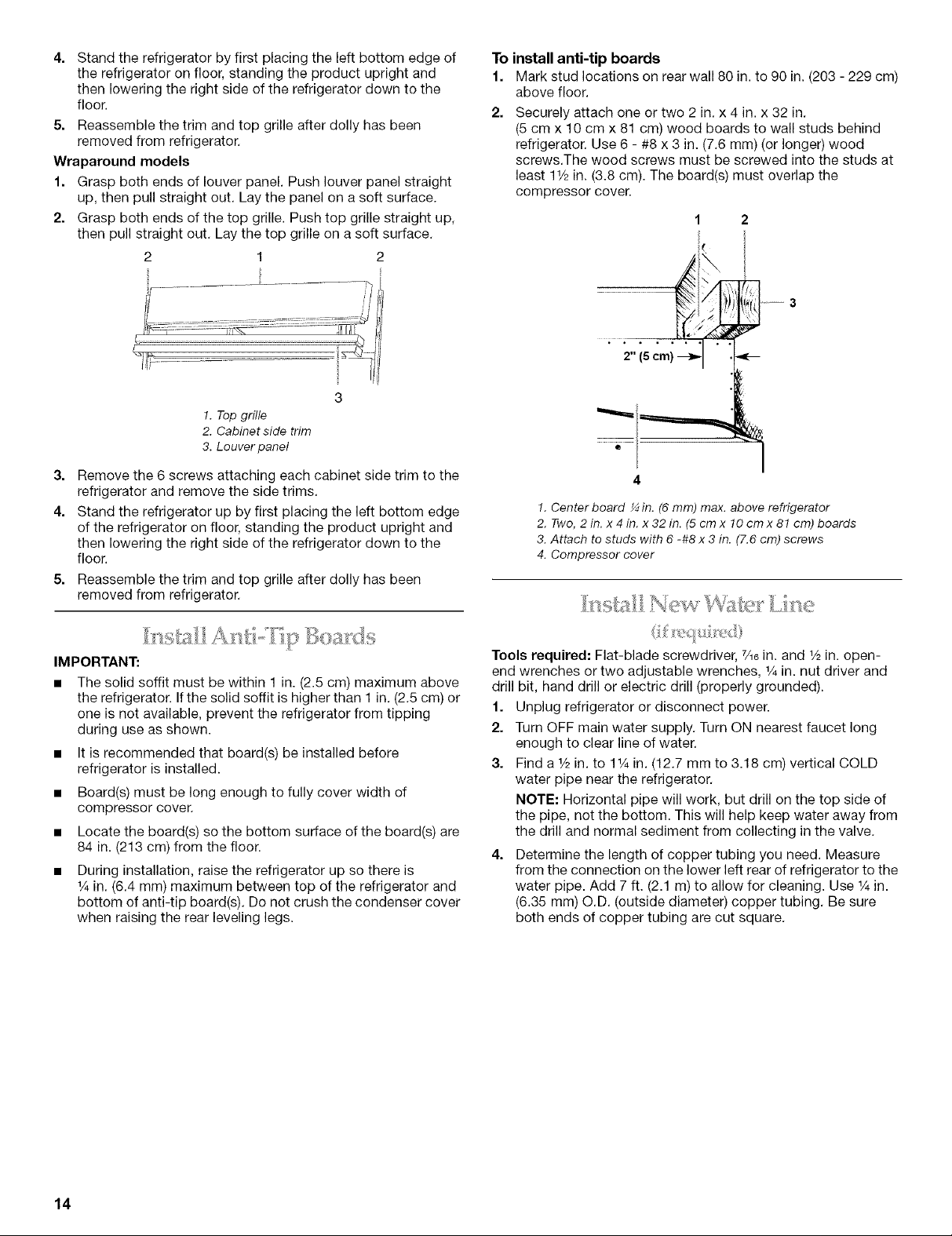
1. Grasp both ends of louver panel. Push louver panel straight
up, then pull straight out. Lay the panel on a soft surface.
2. Grasp both ends of the top grille. Push top grille straight up,
then pull straight out. Lay the top grille on a soft surface.
2 1
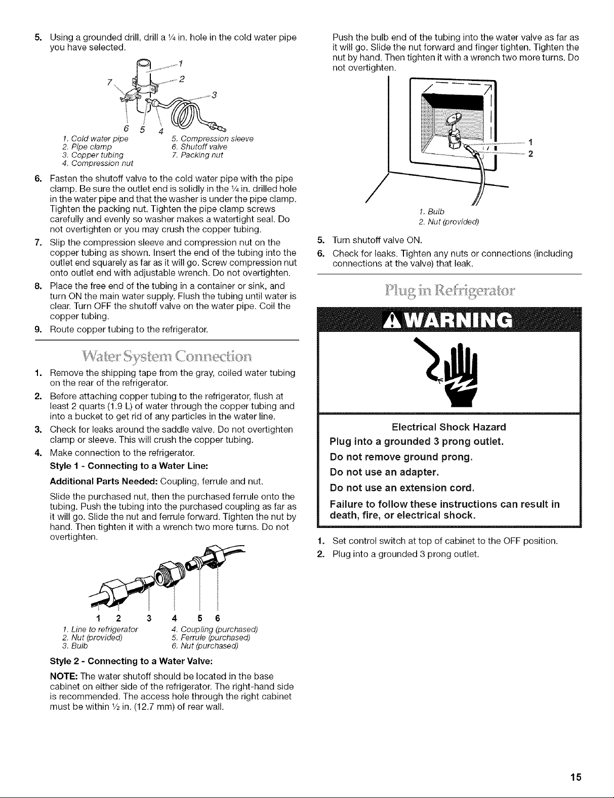
To install anti-tip boards
1. Mark stud locations on rear wall 80 in. to 90 in. (203 - 229 cm)
above floor.
2. Securely attach one or two 2 in. x 4 in. x 32 in.
(5 cm x 10 cm x 81 cm) wood boards to wall studs behind
refrigerator. Use 6 - #8 x 3 in. (7.6 mm) (or longer) wood
screws.The wood screws must be screwed into the studs at
least 1V2in. (3.8 cm). The board(s) must overlap the
compressor cover.
2
3
!. Top grille
2. Cabinet side trim
3. Louver panel
3=
Remove the 6 screws attaching each cabinet side trim to the
refrigerator and remove the side trims.
4.
Stand the refrigerator up by first placing the left bottom edge
of the refrigerator on floor, standing the product upright and
then lowering the right side of the refrigerator down to the
floor.
5=
Reassemble the trim and top grille after dolly has been
removed from refrigerator.
IMPORTANT:
• The solid soffit must be within 1 in. (2.5 cm) maximum above
the refrigerator. If the solid soffit is higher than 1 in. (2.5 cm) or
one is not available, prevent the refrigerator from tipping
during use as shown.
• It is recommended that board(s) be installed before
refrigerator is installed.
• Board(s) must be long enough to fully cover width of
compressor cover.
• Locate the board(s) so the bottom surface of the board(s) are
84 in. (213 cm) from the floor.
During installation, raise the refrigerator up so there is
% in. (6.4 mm) maximum between top of the refrigerator and
bottom of anti-tip board(s). Do not crush the condenser cover
when raising the rear leveling legs.
• ° .....
i.I,/
• °
2" (Scm)
4
1. Center board ¼in. (6 mm) max. above refrigerator
2. Two, 2in. x 4 in. x 32 in. (5 cm x lO cm x 81 cm) boards
3. Attach to studs with 6 -#8 x 3 in. (7.6 cm) screws
4. Compressor cover
Tools required: Flat-blade screwdriver, 7/_6in. and _/2in. open-
end wrenches or two adjustable wrenches, _/4in. nut driver and
drill bit, hand drill or electric drill (properly grounded).
1. Unplug refrigerator or disconnect power.
2. Turn OFF main water supply. Turn ON nearest faucet long
enough to clear line of water.
3. Find a V2 in. to 1% in. (12.7 mm to 3.18 cm) vertical COLD
water pipe near the refrigerator.
NOTE: Horizontal pipe will work, but drill on the top side of
the pipe, not the bottom. This will help keep water away from
the drill and normal sediment from collecting in the valve.
Determine the length of copper tubing you need. Measure
from the connection on the lower left rear of refrigerator to the
water pipe. Add 7 ft. (2.1 m) to allow for cleaning. Use % in.
(6.35 mm)O.D. (outside diameter)copper tubing. Be sure
both ends of copper tubing are cut square.
14
5=
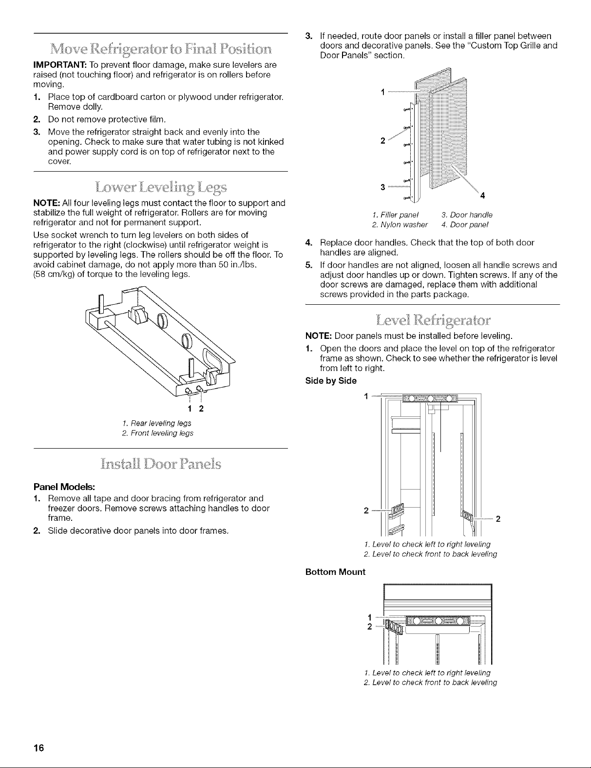
Using a grounded drill, drill a 1/4in. hole in the cold water pipe
you have selected.
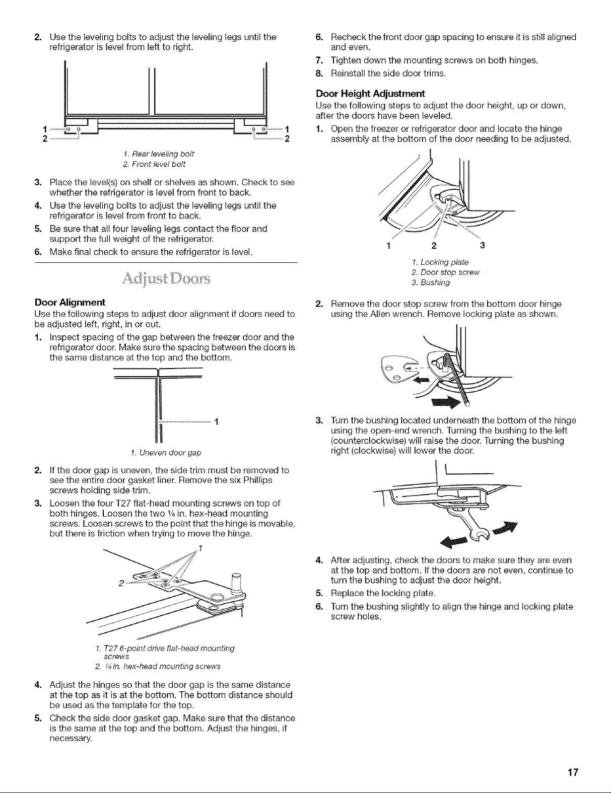
Push the bulb end of the tubing into the water valve as far as
it will go. Slide the nut forward and finger tighten. Tighten the
nut by hand. Then tighten itwith a wrench two more turns. Do
not overtighten.
!. Cold water pipe 5. Compression sleeve
2. Pipe clamp 6. Shutoff valve
3. Copper tubing 7.Packing nut
4. Compression nut
6. Fasten the shutoff valve to the cold water pipe with the pipe
clamp. Be sure the outlet end is solidly in the 1/4in. drilled hole
in the water pipe and that the washer is under the pipe clamp.
Tighten the packing nut. Tighten the pipe clamp screws
carefully and evenly so washer makes a watertight seal. Do
not overtighten or you may crush the copper tubing.
7. Slip the compression sleeve and compression nut on the
copper tubing as shown. Insert the end of the tubing into the
outlet end squarely as far as it will go. Screw compression nut
onto outlet end with adjustable wrench. Do not overtighten.
8. Place the free end of the tubing in a container or sink, and
turn ON the main water supply. Flush the tubing until water is
clear. Turn OFF the shutoff valve on the water pipe. Coil the
copper tubing.
9. Route copper tubing to the refrigerator.
/
1. Remove the shipping tape from the gray, coiled water tubing
on the rear of the refrigerator.
2. Before attaching copper tubing to the refrigerator, flush at
least 2 quarts (1.9 L) of water through the copper tubing and
into a bucket to get rid of any particles in the water line.
3. Check for leaks around the saddle valve. Do not overtighten
clamp or sleeve. This will crush the copper tubing.
4. Make connection to the refrigerator.
Style 1 - Connecting to a Water Line:
Additional Parts Needed: Coupling, ferrule and nut.
Slide the purchased nut, then the purchased ferrule onto the
tubing. Push the tubing into the purchased coupling as far as
it will go. Slide the nut and ferrule forward. Tighten the nut by
hand. Then tighten it with a wrench two more turns. Do not
overtighten.
J/ll
1
2
!. Bulb
2. Nut (provided)
5=
Turn shutoff valve ON.
6.
Check for leaks. Tighten any nuts or connections (including
connections at the valve) that leak.
Electrical Shock Hazard
Plug into a grounded 3 prong outlet.
Do not remove ground prong.
Do not use an adapter.
Do not use an extension cord.
Failure to follow these instructions can result in
death, fire, or electrical shock.
1. Set control switch at top of cabinet to the OFF position.
2. Plug into a grounded 3 prong outlet.
1 2
1. Line to refrigerator
2. Nut (provided)
3. Bulb
3 4 5 6
4. Coupling (purchased)
5. Ferrule (purchased)
6. Nut (purchased)
Style 2 - Connecting to a Water Valve:
NOTE: The water shutoff should be located in the base
cabinet on either side of the refrigerator. The right-hand side
is recommended. The access hole through the right cabinet
must be within 1/2in. (12.7 mm) of rear wall.
15
IMPORTANT: To prevent floor damage, make sure levelers are
raised (not touching floor) and refrigerator is on rollers before
moving.
1. Place top of cardboard carton or plywood under refrigerator.
Remove dolly.
2. Do not remove protective film.
3. Move the refrigerator straight back and evenly into the
opening. Check to make sure that water tubing is not kinked
and power supply cord is on top of refrigerator next to the
cover.
NOTE: All four leveling legs must contact the floor to support and
stabilize the full weight of refrigerator. Rollers are for moving
refrigerator and not for permanent support.
Use socket wrench to turn leg levelers on both sides of
refrigerator to the right (clockwise) until refrigerator weight is
supported by leveling legs. The rollers should be off the floor. To
avoid cabinet damage, do not apply more than 50 in./Ibs.
(58 cm/kg) of torque to the leveling legs.
If needed, route door panels or install a filler panel between
doors and decorative panels. See the "Custom Top Grille and
Door Panels" section.
1. Filler panel 3. Door handle
2. Nylon washer 4. Door panel
4.
Replace door handles. Check that the top of both door
handles are aligned.
5.
If door handles are not aligned, loosen all handle screws and
adjust door handles up or down. Tighten screws. If any of the
door screws are damaged, replace them with additional
screws provided in the parts package.
1. Rear leveling legs
2. Front leveling legs
Panel Models:
1. Remove all tape and door bracing from refrigerator and
freezer doors. Remove screws attaching handles to door
frame.
2. Slide decorative door panels into door frames.
_2
NOTE: Door panels must be installed before leveling.
1. Open the doors and place the level on top of the refrigerator
frame as shown. Check to see whether the refrigerator is level
from left to right.
Side by Side
2--_ ,--2
1.Level to check left to right leveling
2. Level to check front toback leveling
Bottom Mount
16
1. Level to check left to right leveling
2. Level to check front to back leveling
2=
Use the leveling bolts to adjust the leveling legs until the
refrigerator is level from left to right.
6=
Recheck the front door gap spacing to ensure it is still aligned
and even.
7.
Tighten down the mounting screws on both hinges.
8.
Reinstall the side door trims.
h
1. Rear leveling bolt
2. Front level bolt
3. Place the level(s) on shelf or shelves as shown. Check to see
whether the refrigerator is level from front to back.
4. Use the leveling bolts to adjust the leveling legs until the
refrigerator is level from front to back.
5. Be sure that all four leveling legs contact the floor and
support the full weight of the refrigerator.
6. Make final check to ensure the refrigerator is level.
Boor Alignment
Use the following steps to adjust door alignment if doors need to
be adjusted left, right, in or out.
1. Inspect spacing of the gap between the freezer door and the
refrigerator door. Make sure the spacing between the doors is
the same distance at the top and the bottom.
Door Height Adjustment
Use the following steps to adjust the door height, up or down,
after the doors have been leveled.
1. Open the freezer or refrigerator door and locate the hinge
assembly at the bottom of the door needing to be adjusted.
1 2 3
1. Locking plate
2. Door stop screw
3. Bushing
Remove the door stop screw from the bottom door hinge
using the Allen wrench. Remove locking plate as shown.
..................... 1
1.Unevendoor gap
2. If the door gap is uneven, the side trim must be removed to
see the entire door gasket liner. Remove the six Phillips
screws holding side trim.
3. Loosen the four T27 flat-head mounting screws on top of
both hinges. Loosen the two 1/4in. hex-head mounting
screws. Loosen screws to the point that the hinge is movable,
but there is friction when trying to move the hinge.
!. T27 6-point drive flat-head mounting
screws
2. ¼ in. hex-head mounting screws
4. Adjust the hinges so that the door gap is the same distance
at the top as it is at the bottom. The bottom distance should
be used as the template for the top.
5. Check the side door gasket gap. Make sure that the distance
is the same at the top and the bottom. Adjust the hinges, if
necessary.
Turn the bushing located underneath the bottom of the hinge
using the open-end wrench. Turning the bushing to the left
(counterclockwise) will raise the door. Turning the bushing
right (clockwise) will lower the door.
4. After adjusting, check the doors to make sure they are even
at the top and bottom. If the doors are not even, continue to
turn the bushing to adjust the door height.
5. Replace the locking plate.
6. Turn the bushing slightly to align the hinge and locking plate
screw holes.
17
 Loading...