

Kitchenaid KSSV42FM, KSSS48QM, KSSS42QM, KSSS36QM, KSSS36FM User Manual
...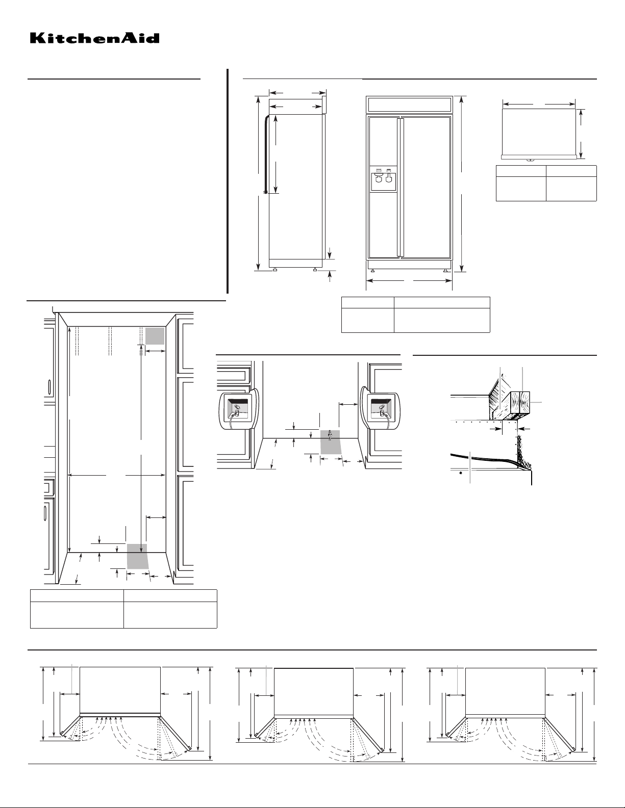
Side by Side Built-in Refrigerator
®
PRODUCT MODEL NUMBERS OVERALL DIMENSIONS
CABINET OPENING DIMENSIONS
Electrical: A 115-volt, 60-Hz, AC-only, 15- or
20-ampere, fused, electrical supply is required. A
time-delay fuse or circuit breaker is recommended.
It is recommended that a separate circuit serving
only this appliance be provided.
Cold Water Supply: Connect the ice maker to a
cold water line with water pressure between 20
and 120 psi (138 - 827 kPa). If you have questions
about your water pressure, call your utility company).
Because Whirlpool Corporation policy includes a continuous commitment to improve
our products, we reserve the right to change materials and specifications without notice.
Dimensions are for planning purposes only. For complete details, see Installation
Instructions packed with product. Specifications subject to change without notice.
Ref. 2266811
09-10-04
KSSC36FM
KSSC36QM
KSSC42FM
KSSC42QM
KSSC48FM
KSSC48QM
KSSO36FM
KSSO36QM
KSSO42FM
KSSO42QM
KSSO48FM
KSSO48QM
KSSP36QM
KSSP42QM
KSSP48QM
KSSS36FM
KSSS36QM
KSSS42FM
KSSS42QM
KSSS48FM
KSSS48QM
KSSV42FM
Top
view
Front view
Side
view
m
)
36 in. (91 cm)
models
42 in. (106 cm)
models
48 in. (122 cm)
models
* When leveling legs are
fully extended to 1-1/4 in.
(32 mm) below rollers,
add 1-1/8 in. (29 mm) to
the height dimensions.
DOOR SWING DIMENSIONS
BA
C
2" (5 cm)
D
A. Center board 1/4 in. (6 mm) max. above refrigerator
B. Two, 2 in. x 4 in. x 32 in. (5 cm x 10 cm x 81 cm) boards
C. Attach to studs with 6 -#8 x 3 in. (7.6 cm) screws
D. Compressor cover
ANTI-TIP REQUIREMENTS
The solid soffit must be within 1 in. (2.5 cm) maximum above
the refrigerator. If the solid soffit is higher than 1 in. (2.5 cm) or
one is not available, prevent the refrigerator from tipping during
use as shown.
Board(s) must be long enough to fully cover the width of the
compressor cover.
Locate the board(s) so the bottom surface of the board(s) are
84 in. (213 cm) from the floor.
Securely attach one or two 2 in. x 4 in. x 32 in. (5 cm x 10 cm x
81 cm) wood boards to wall studs behind refrigerator. Use 6 #8 x 3 in. (7.6 mm) (or longer) wood screws. The wood screws
must be screwed into the studs at least 1-1/2 in. (3.8 cm). The
board(s) must overlap the compressor cover.
WATER SUPPLY REQUIREMENTS
If water shutoff valve is located in base cabinet, access hole
through side of cabinet must be within 1/2" (12.7 mm) of rear
wall. Right side cabinet is recommended. If water shutoff valve
is not in cabinets, water line can come through rear wall or floor
in shaded area dimensioned above.
Other model series dispensing,
and non-dispensing, with different
styling are available.
251/
*831/
(211 cm)
8"
8"
(64 cm)
231/
2"
(60 cm)
24" (61 cm)
Power Cord
1
*3
/
2"(9cm)
*831/
8"
(211 cm)
A
(see chart following)
Model Width A (Trim edge to trim edge)
36 in. (91 cm)
42 in. (106 cm)
48 in. (122 cm)
1
in. (92 cm)
36
/4
1
/4
42 in. (107 cm)
1
48 in. (123 cm)
/4
A
Model Width A
36 in. (91 cm)
42 in. (106 cm)
48 in. (122 cm)
35 in. (89 cm)
41 in. (104 cm)
47 in. (119 cm)
251/
8"
(64 cm)
80" - 90"
(203-229 cm)
831/4" (211.5 cm) min.
3
84
/4" (215 cm) max.
to bottom of solid soffit
(see chart following)
3" (7.6 cm)
231/2"
(60 cm) min.
(28 cm)
A
Width
11"
77"
(196 cm)
6"
(15.2 cm)
4"
(10.2 cm)
6"
(15.2 cm)
(15.2 cm)
6"
Model Width A (as shown above)
36 in. (91.4 cm)
42 in. (106.7 cm)
48 in. (121.9 cm)
1
35 in. (90.2 cm)
/4
1
/4
41 in. (105.4 cm)
1
/4
47 in. (120.7 cm)
1
14
/2"
(37 cm)
1
/16"
36
(92 cm)
1
/2"
38
(98 cm)
130˚
110˚
90˚
110˚
130˚
40"
(102 cm)
3
/4"
19
(50 cm)
90˚
431/2"
(110cm)
6"
(15.2 cm)
3" (7.6 cm)
11"
231/2"
(60 cm) min.
1
/2"
17
(44 cm)
38"
(97 cm)
41"
(104cm)
(28 cm)
6"
6"
(15.2 cm)
(15.2 cm)
1
23
(59 cm)
/4"
429/16"
(108 cm)
90˚
110˚
130˚
130˚
110˚
90˚
3
19
/4"
(50 cm)
(119c
40"
(102 cm)
431/2"
47"
(110cm)
90˚
110˚
130˚
130˚
110˚
90˚
451/4"
(115 cm)
3
26
/4"
(68 cm)
501/2"
(128 cm
 Loading...