

KitchenAid KSSC36FKB00, KSSC36FKS00, KSSC36QKS00, KSSC42FKB00, KSSC42FKS00 Service Manual
...
TECHNICAL EDUCATION
www.Appliantology.org
JOB AID 4317326A
JOB AID 4317326A
MODELS:
KAR-11
KSSC36FKB00
KSSC36FKS00
KSSC36QKS00
KSSC42FKB00
KSSC42FKS00
KSSC42QKS00
KSSC48FKB00
KSSC48FKS00
KSSC48QKS00
KSSP36QKS00
KSSP42QKS00
KSSP48QKS00
KSSS36FKB00
KSSS36FKT00
KSSS36FKW00
KSSS36FKX00
KSSS36QKB00
KSSS36QKT00
KSSS36QKW00
KSSS36QKX00
2001 K MODEL
KSSS42FKB00
KSSS42FKT00
KSSS42FKW00
KSSS42FKX00
KSSS42QKB00
KSSS42QKT00
KSSS42QKW00
KSSS42QKX00
KSSS48FKB00
KSSS48FKT00
KSSS48FKW00
KSSS48FKX00
KSSS48QKB00
KSSS48QKT00
KSSS48QKW00
KSSS48QKX00
BUILT-IN SIDE-BY-SIDE
REFRIGERATOR WITH VARIABLE
CAPACITY COMPRESSOR
JOB AID 4317326A

WHIRLPOOL CORPORATION assumes no responsibility for any repairs made
on our products by anyone other than Authorized Service Technicians.
This KitchenAid Job Aid, 2001 K Model Built-In Side-By-Side Refrigerator With Variable Capacity
Compressor (Part No. 4317326A), provides the technician with information on the installation and
service of the Built-In Side-By-Side Refrigerator. It is to be used as a training Job Aid and Service
or “Tech Sheet” provided with the refrigerator.
The Wiring Diagrams and Strip Circuits used in this Job Aid are typical and should be used for
training purposes only. Always use the Wiring Diagram supplied with the product when servicing
the unit.
The goal of this Job Aid is to provide detailed information that will enable the service technician to
The objectives of this Job Aid are to:
• Understand and follow proper safety precautions.
• Successfully troubleshoot and diagnose malfunctions.
• Successfully perform necessary repairs.
• Successfully return the refrigerator to its proper operational status.
Copyright © 2002, Whirlpool Corporation, Benton Harbor, MI 49022
www.Appliantology.org
- ii -
- ii -

TABLE OF CONTENTS
GENERAL
Safety First...................................................................................................................
Anti-Tip Requirements.................................................................................................. 1-2
Specifications.................................................................................................................
THEORY OF OPERATION
COMPONENT ACCESS
Component Locations ........................................................................................................ 4-1
And The Main Control Board Assembly.......................................................................... 4-4
The Defrost Heater, And The Evaporator ..................................................................... 4-10
COMPONENT TESTING
Thermistor.....................................................................................................................
Condenser Fan Motor ........................................................................................................ 5-2
Compressor & Inverter....................................................................................................... 5-3
5-4
-5
Crush/Cube Solenoid......................................................................................................... 5-6
Water Valve Solenoid ........................................................................................................ 5-7
www.Appliantology.org
- iii -
- iii -

Pre-Diagnostics Checks ................................................................................................. 6-1
Diagnostics Mode ........................................................................................................... 6
-1
Water Filter Input (WFI) Test .......................................................................................... 6-2
Troubleshooting Chart ....................................................................................................... 6-3
WIRING DIAGRAMS & STRIP CIRCUITS
Wiring Diagram—Bottom Mount ........................................................................................ 7-1
Wiring Diagram—Side-By-Side Models ............................................................................. 7-2
Strip Circuits .................................................................................................................
www.Appliantology.org
- iv -
- iv -
electrical shock.
GENERAL
SAFETY FIRST
Your safety and the safety of others is very important.
We have provided many important safety messages in this Job Aid and on the appliance. Always
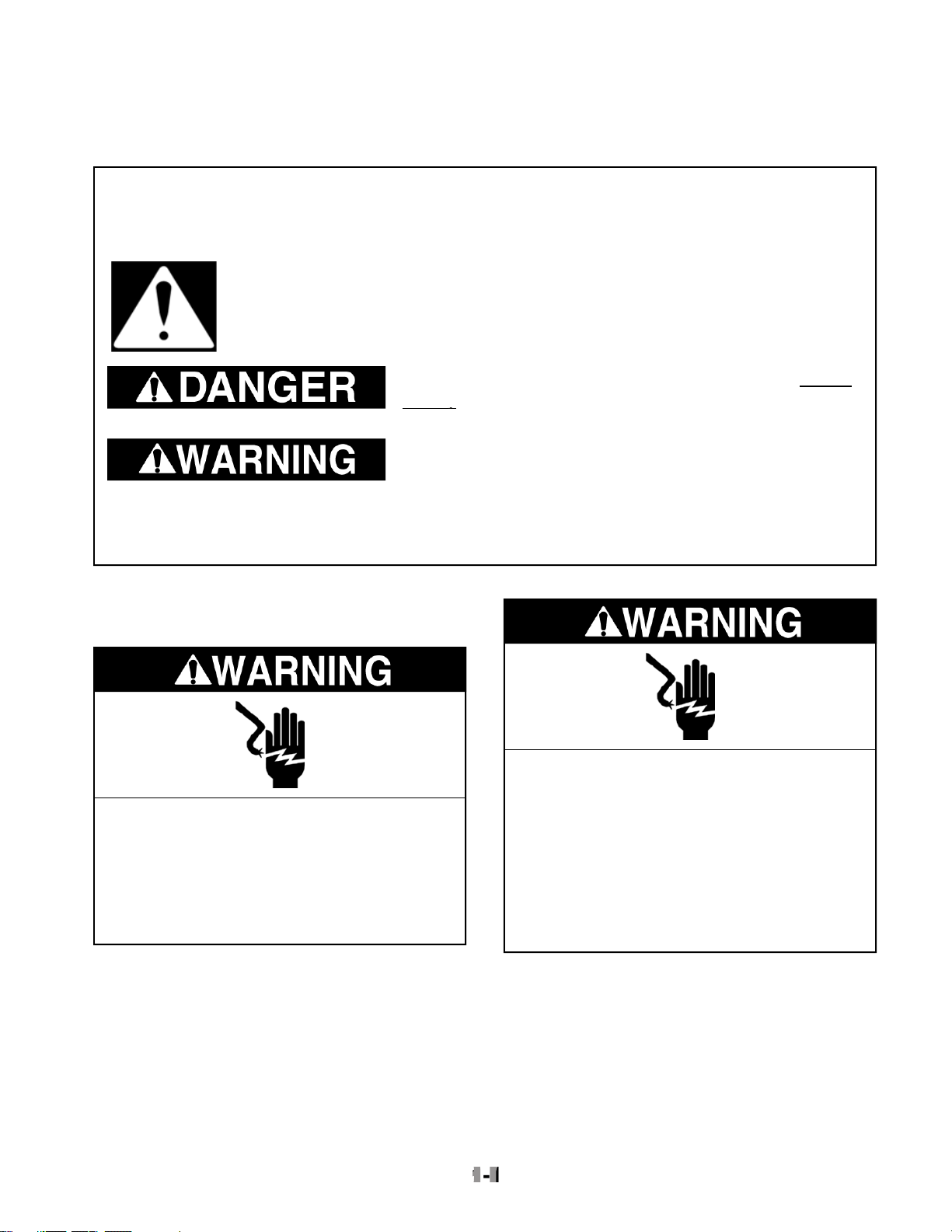
This is the safety alert symbol.
This symbol alerts you to hazards that can kill or hurt you and others.
All safety messages will follow the safety alert symbol and either the word
“DANGER” or “WARNING.” These words mean:
All safety messages will tell you what the potential hazard is, tell you how to reduce the chance
of injury, and tell you what can happen if the instructions are not followed.
You can be killed or seriously injured if you don’t
diately follow instructions.
diately follow instructions.
You can be killed or seriously injured if you don’t follow
www.Appliantology.org
assembly. The new control assembly may ap-
failure may occur at a later date due to ESD
stress.
• Use an antistatic wrist strap. Connect the
wrist strap to a green ground connection
touch your finger repeatedly to a green ground
connection point or unpainted metal in the
appliance.
• Before removing the part from its package,
touch the antistatic bag to a green ground
connection point or unpainted metal in the
appliance.
• Avoid touching electronic parts or terminal
contacts. Handle the electronic control as-
sembly by the edges only.
• When repackaging the failed electronic con-
trol assembly in an antistatic bag, observe
the above instructions.
Connect green ground wire to ground
screw.
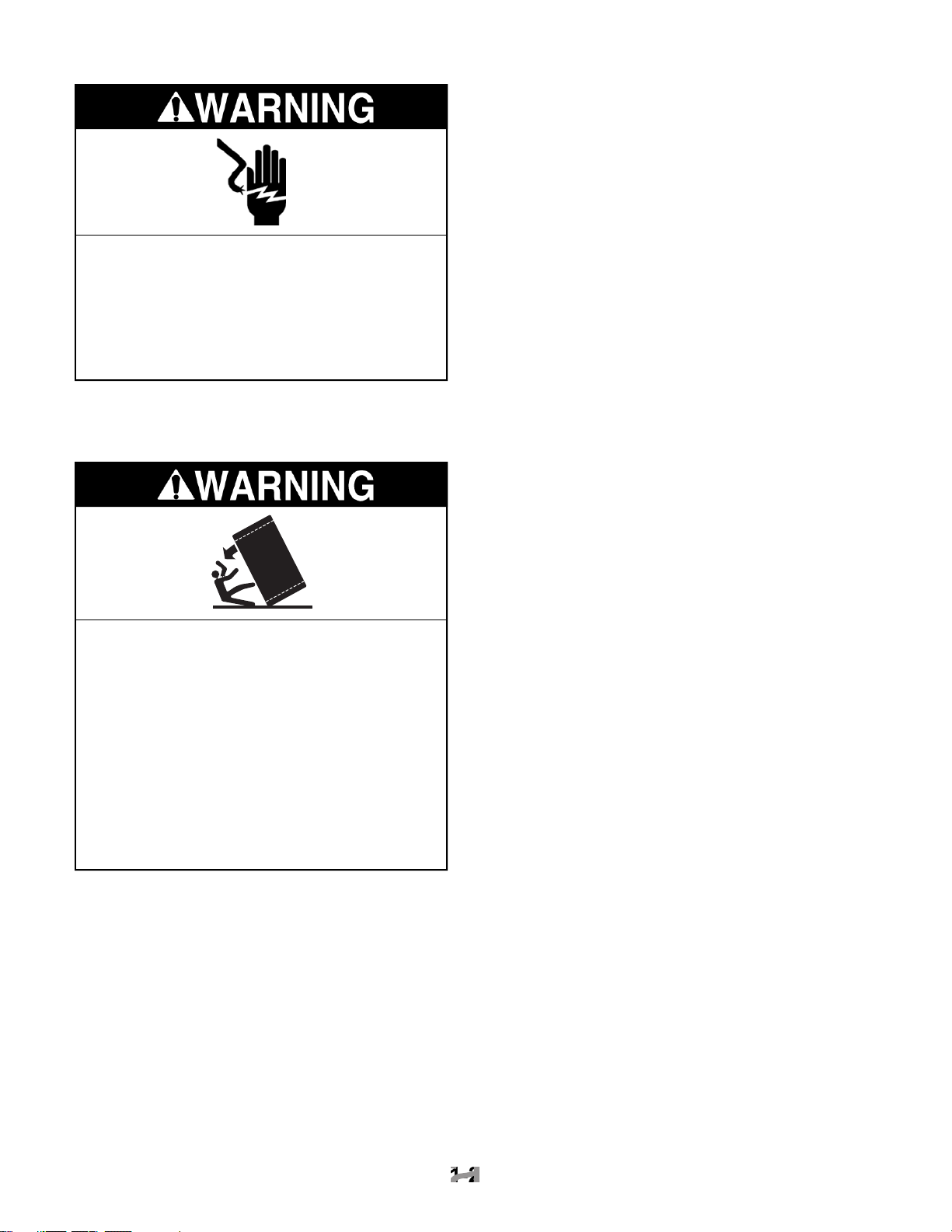
electrical shock.
Tip Over Hazard
when not completely installed.
tor is completely installed.
serious injury.
www.Appliantology.org
SERIAL NUMBER
MODEL NUMBER K SS S 42 Q K X 0 0
www.Appliantology.org
PRODUCT GROUP
K = KitchenAid Brand
PRODUCT IDENTIFICATION
BR = Bottom Mount Right Hand Hinge
BL = Bottom Mount Left Hand Hinge
SS = Side-By-Side Built-In
MERCHANDISING SCHEME/SERIES
C = Wrap Around Stainless Steel
P = Factory Installed Panel Kit
S = Framed Trim Kit (Panels Not Included)
CAPACITY/ SIZE
36 = 36″ Width
42 = 42″ Width
48 = 48″ Width
FEATURES
D = Ice & Water Dispensing
F = Factory Installed Ice Maker w/Filter
M = Factory Installed Ice Maker wo/Filter
Q = Ice/Crushed Ice & Water Dispensing w/Filter
YEAR OF INTRODUCTION
K = 2001
COLOR CODE
X = No Color Used
ENERGY POWER CONSUMPTION CHANGE
0 = Original, 1 = 1st Change, 2 = 2nd Change, Etc.
ENGINEERING CHANGE (NUMERIC)
0 = Original, 1 = 1st Change, 2 = 2nd Change, Etc.
SERIAL NUMBER Q L 30 10003
MANUFACTURING SITE
Q = LaVergne, TN
YEAR OF PRODUCTION
L = 2001
WEEK OF PRODUCTION
30th WEEK
PRODUCT SEQUENCE NUMBER
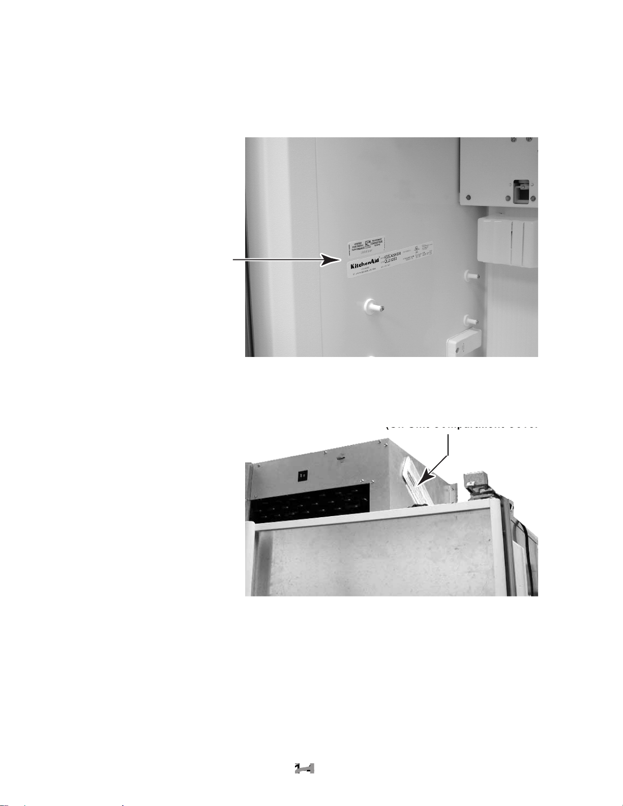
AND TECH SHEET LOCATIONS
The Model/Serial Number Label and Tech Sheet locations are shown below.
(Freezer Compartment)
Tech Sheet Location
(On Unit Compartment Cover)
(On Unit Compartment Cover)
www.Appliantology.org
SPECIFICATIONS
Model Number KSSC36FKB KSSC36FKS KSSC36QKS
www.Appliantology.org
Model Description
Size-Configuration 36" 36" 36"
Refrigerator Volume (Cu Ft) 13 13 13
Freezer Volume (Cu Ft) 7.5 7.5 7.4
Crated Weight (lbs) 500 500 500
Refrigerant 134a 134a 134a
Standard Warranty (Months) 24 24 24
Full Liner And Sealed System Warranty (Months) 72 72 72
Sealed System Warranty (Months) 144 144 144
Model Number KSSC42FKB KSSC42FKS KSSC42QKS
Model Description
Size-Configuration 42" 42" 42"
Refrigerator Volume (Cu Ft) 13 15.6 15.7
Freezer Volume (Cu Ft) 9.1 9.1 8.9
Crated Weight (lbs) 552 552 552
Refrigerant 134a 134a 134a
Standard Warranty (Months) 24 24 24
Full Liner And Sealed System Warranty (Months) 72 72 72
Sealed System Warranty (Months) 144 144 144
Model Number KSSC48FKB KSSC48FKS KSSC48QKS
Model Description
Size-Configuration 48" 48" 48"
Refrigerator Volume (Cu Ft) 18.3 18.3 18.4
Freezer Volume (Cu Ft) 10.7 10.7 10.5
Crated Weight (lbs) 579 579 579
Refrigerant 134a 134a 134a
Standard Warranty (Months) 24 24 24
Full Liner And Sealed System Warranty (Months) 72 72 72
Sealed System Warranty (Months) 144 144 144
Model Number KSSP36QKS KSSP42QKS KSSP48QKS
Model Description
Size-Configuration 36" 42" 48"
Refrigerator Volume (Cu Ft) 13 15.7 18.4
Freezer Volume (Cu Ft) 7.4 8.9 10.5
Crated Weight (lbs) 500 552 579
Refrigerant 134a 134a 134a
Standard Warranty (Months) 24 24 24
Full Liner And Sealed System Warranty (Months) 72 72 72
Sealed System Warranty (Months) 144 144 144
Black Architect Series - Non-Disp.
with water filter
Black Architect Series - Non-Dispenser
Black Architect Series - Non-Dispenser
with water filter
with water filter
Stainless Steel - Dispenser - Factory
Installed Panels with water filter
Architect Series - Non-Dispenser with
Architect Series - Non-Dispenser with
Stainless Steel - Dispenser - Factory
water filter
Architect Series - Non-Dispenser
with water filter
water filter
Installed Panels with water filter
Stainless Steel Architect Series -
Disp. - with water filter
Stainless Steel Architect -
Dispenser with water filter
Stainless Steel Architect Series
with Dispenser with Water Filter
Stainless Steel - Dispenser - Factory
Installed Panels with Water Filter
Model Number KSSS36FKB KSSS36FKT KSSS36FKW
www.Appliantology.org
Model Description
Size-Configuration 36" 36" 36"
Refrigerator Volume (Cu Ft) 13 13 13
Freezer Volume (Cu Ft) 7.5 7.5 7.5
Crated Weight (lbs) 500 500 500
Refrigerant 134a 134a 134a
Standard Warranty (Months) 24 24 24
Full Liner And Sealed System Warranty (Months) 72 72 72
Sealed System Warranty (Months) 144 144 144
Model Number KSSS36FKX KSSS36QKB KSSS36QKT
Model Description
Size-Configuration 36" 36" Side By Side 36" Side by Side
Refrigerator Volume (Cu Ft) 13 13 13
Freezer Volume (Cu Ft) 7.5 7.4 7.4
Crated Weight (lbs) 500 500 500
Refrigerant 134a 134a 134a
Standard Warranty (Months) 24 24 24
Full Liner And Sealed System Warranty (Months) 72 60 60
Sealed System Warranty (Months) 144 144 144
Model Number KSSS36QKW KSSS36QKX KSSS42FKB
Model Description
Size-Configuration 36" Side By Side 36" Side By Side 42"
Refrigerator Volume (Cu Ft) 13 13 15.6
Freezer Volume (Cu Ft) 7.4 7.4 9.1
Crated Weight (lbs) 500 500 552
Refrigerant 134a 134a 134a
Standard Warranty (Months) 24 24 24
Full Liner And Sealed System Warranty (Months) 60 60 72
Sealed System Warranty (Months) 144 144 144
Model Number KSSS42FKT KSSS42FKW KSSS42FKX
Model Description
Size-Configuration 42" 42" 42"
Refrigerator Volume (Cu Ft) 15.6 15.6 15.6
Freezer Volume (Cu Ft) 9.1 9.1 9.1
Crated Weight (lbs) 552 552 552
Refrigerant 134a 134a 134a
Standard Warranty (Months) 24 24 24
Full Liner And Sealed System Warranty (Months) 72 72 72
Sealed System Warranty (Months) 144 144 144
Black Trim -Custom Panels Required-
Non-Dispenser with water filter
Brushed Aluminum Trim -Custom Panels
Required-Non-Dispenser with water filter
KitchenAid White Dispenser
with Water Filter
Biscuit Trim - Non-Dispenser with water
filter- Custom Panels Required
Biscuit Trim -Custom Panels Required-
Non-Dispenser with water filter
KitchenAid Black
Dispenser Water Filter
KitchenAid Black Dispenser
with Water Filter
White Trim - Non-Dispenser with water
filter- Custom Panels Required
White Trim-Non-Dispenser-Custom
Panels Required with water filter
KitchenAid Biscuit
Dispenser Water Filter
Black Trim - Non-Dispenser with water
filter- Custom Panels Required
Brushed Aluminum Trim - Non-Dispenser
with water filter- Custom Panels Required
Model Number KSSS42QKB KSSS42QKT KSSS42QKW
www.Appliantology.org
Model Description
Size-Configuration 42" Side by Side 42" Side by Side 42" Side by Side
Refrigerator Volume (Cu Ft) 15.7 15.7 15.7
Freezer Volume (Cu Ft) 8.9 8.9 8.9
Crated Weight (lbs) 552 552 552
Refrigerant 134a 134a 134a
Standard Warranty (Months) 24 24 24
Full Liner And Sealed System Warranty (Months) 72 72 72
Sealed System Warranty (Months) 144 144 144
Model Number KSSS42QKX KSSS48FKB KSSS48FKT
Model Description
Size-Configuration 42" 48" 48"
Refrigerator Volume (Cu Ft) 15.7 18.3 18.3
Freezer Volume (Cu Ft) 8.9 10.7 10.7
Crated Weight (lbs) 552 579 579
Refrigerant 134a 134a 134a
Standard Warranty (Months) 24 24 24
Full Liner And Sealed System Warranty (Months) 72 72 72
Sealed System Warranty (Months) 144 144 144
Model Number KSSS48FKW KSSS48FKX KSSS48QKB
Model Description
Size-Configuration 48" 48" 48" Side by Side
Refrigerator Volume (Cu Ft) 18.3 18.3 18.4
Freezer Volume (Cu Ft) 10.7 10.7 10.5
Crated Weight (lbs) 579 579 579
Refrigerant 134a 134a 134a
Standard Warranty (Months) 24 24 24
Full Liner And Sealed System Warranty (Months) 72 72 72
Sealed System Warranty (Months) 144 144 144
Model Number KSSS48QKT KSSS48QKW KSSS48QKX
Model Description
Size-Configuration 48" Side by Side 48" Side by Side 48" Side by Side
Refrigerator Volume (Cu Ft) 18.4 18.4 18.4
Freezer Volume (Cu Ft) 10.5 10.5 10.5
Crated Weight (lbs) 579 579 579
Refrigerant 134a 134a 134a
Standard Warranty (Months) 24 24 24
Full Liner And Sealed System Warranty (Months) 72 72 72
Sealed System Warranty (Months) 144 144 144
KitchenAid Black Dispenser
Water with Filter
Black Dispenser-Brushed Aluminum
Trim-Custom Panels Required
White Trim Model-Custom Panels Required-
Non-Dispenser with water filter
KitchenAid Biscuit Dispenser
with Water Filter
KitchenAid Biscuit
with Water Filter
Black Trim Model-Custom
Panels Required-Non-Dispenser
with water filter
Brushed Aluminum Trim Model-
Custom Panels Required-Non-
Dispenser with water filter
KitchenAid White Dispenser
Water with Filter
KitchenAid White Water Filter
Biscuit Trim Model-Custom Panels
Required-Non-Dispenser with water filter
KitchenAid Black Dispenser
Water with Filter
KitchenAid Water Filter Black Dispenser-
Brushed Aluminum Trim-

®
BUILT-IN REFRIGERATOR WARRANTY
TWO-YEAR FULL WARRANTY ON REFRIGERATOR
and maintained according to instructions attached to or furnished with the product, KitchenAid will pay for factory
specified replacement parts and repair labor costs to correct defects in materials or workmanship. Replacement parts
and labor costs to correct defects in light bulbs, one year. Service must be provided by a KitchenAid designated
service company.
Water filter cartridge: 30 day limited warranty on water filter. For 30 days from the date of purchase, when this filter
for replacement parts to correct defects in materials and workmanship.
THIRD THROUGH SIXTH YEAR LIMITED WARRANTY
to instructions attached to or furnished with the product, KitchenAid will pay for factory specified replacement parts
and repair labor costs to correct defects in materials or workmanship in the sealed refrigeration system. These parts
are: compressor, evaporator, condenser, dryer, and connecting tubing. Service must be performed by a KitchenAid
designated service company.
SEVENTH THROUGH TWELFTH YEAR LIMITED WARRANTY
to instructions attached to or furnished with the product, KitchenAid will pay for factory specified replacement parts
to correct defects in materials or workmanship in the sealed refrigeration system. These parts are: compressor,
evaporator, condenser, dryer, and connecting tubing.
furnished with the product, KitchenAid will replace all Door Bins due to defective materials or workmanship.
2. Repairs when the refrigerator is used in other than normal, single-family household use.
3. Pickup and delivery. The refrigerator is designed to be repaired in the home.
4. Damage resulting from accident, alteration, misuse, abuse, fire, flood, improper installation, acts of God, or use
of products not approved by KitchenAid or KitchenAid Canada.
5. Any food or medicine loss due to product failure.
6. Repairs to parts or systems resulting from unauthorized modifications made to the appliance.
7. Removal and replacement of trim or decorative panels that interfere with servicing the product.
8. Labor or parts installed by any non-designated service company during the full warranty period, unless approved
by KitchenAid before service is performed.
9. In Canada, travel or transportation expenses for customers who reside in remote areas.
TIAL DAMAGES.
Some states or provinces do not allow the exclusion or limitation of incidental or consequential damages, so this
exclusion or limitation may not apply to you. This warranty gives you specific legal rights, and you may also have
other rights which vary from state to state or province to province.
Outside the 50 United States and Canada, a different warranty may apply. Contact your authorized KitchenAid
dealer to determine if another warranty applies.
shooting,” additional help can be found by checking the “Assistance or Service” section or by calling the
(toll-free), from anywhere in the U.S.A. In Canada,
contact your designated KitchenAid Canada Appliance service company or call:
www.Appliantology.org
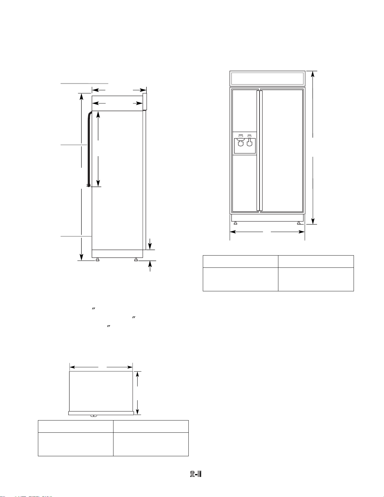
INSTALLATION INFORMATION
Side View
ers extended 1/8
(3 mm) below the rollers. For
(32 mm) below
the rollers, add 1-1/8
(29 mm) to this dimen-
sion.
Top View
831/
8
"
(211 cm)
A
(see chart following)
Width of Refrigerator
36" (91 cm)
42
"
(106 cm)
48
"
(122 cm)
36-1/4
"
(92 cm)
42-1/4
"
(107 cm)
48-1/4
"
(123 cm)
Model Width A (as shown above)
the distance from outside trim to outside trim.
www.Appliantology.org
2-1
2-1
1
2
831/8"
(211 cm)*
3
251/8"
(64 cm)
231/2"
(60 cm)
24"
(61 cm)
1
/2" (9 cm)*
3
Model Width A
36" (91 cm)
42
"
(106 cm)
"
(122 cm)
48
1. 25-1/8" (64 cm) dimension is to front of top grille
2. Power cord (24") (61 cm)
3. 5 ft. (1.5 m) water line tubing taped to back
A
25-1/8"
(64 cm)
35
"
(89 cm)
41
"
(104 cm)
"
(119 cm)
47

1
d
Openings
The built-in refrigerator can be installed into a
of cabinets using a side panel to enclose the
(12.7 mm) clearance to remove the top
grille and for proper air flow.
Wall studs must be located on the rear wall 80
to 90
(203 - 229 cm) above the floor.
The solid soffit must be within 1
(2.5 cm)
soffit is higher than 1
(2.5 cm), or one is not
available, then the refrigerator must be braced
to prevent tipping during use. See “Anti-Tip
A grounded electrical outlet should be placed
(10.2 cm) from the
The water shutoff should be located in the base
cabinet on either side of the refrigerator. The
through the right cabinet must be within 1/2
A 1/2
(12.7 mm) hole for plumbing should be
within the bottom shaded area. The water line
can be through the floor or wall. If the recom-
tional plumbing is necessary.
80" - 90"
(203-229 cm)
4"
(10.2 cm)
6"
(15.2 cm)
3" (7.6 cm)
83-1/4" (211.5 cm) min.
84-3/4" (215 cm) max.
to bottom of solid soffit.
(60 cm) min.
11"
(28 cm)
77"
(196 cm)
A
Width
(see chart following)
1
2
4
6"
(15.2 cm)
6"
(15.2 cm)
3
1. Stud location
2. Grounded electrical outlet location
3. Recommended water shutoff valve location
4. Plumbing hole and water line location (wall or floor)
36" (91.4 cm)
42
"
(106.7 cm)
48
"
(121.9 cm)
35-1/2
"
(90.2 cm)
41-1/2
"
(105.4 cm)
47-1/2
"
(120.7 cm)
Model Width A (as shown above)
Width of Opening:
23-1/2"
www.Appliantology.org
2-2
2-2
1. A 1/2" (12.7 mm) space is require
WATER SUPPLY REQUIREMENTS
• If you turn the refrigerator on before the
water line is connected, turn the ice maker
off.
• All installations must meet local plumbing
code requirements.
• Use copper tubing and check for leaks. In-
stall copper tubing only in areas where tem-
A kit is available with a 1/4
(6.35 mm) saddle-
type shutoff valve, a union, and copper tubing.
saddle-type valve complies with local plumb-
water flow and clog easily.
Connect the ice maker to a cold water line with
water pressure between 15 and 100 psi (103 -
690 kPa). If you have questions about water
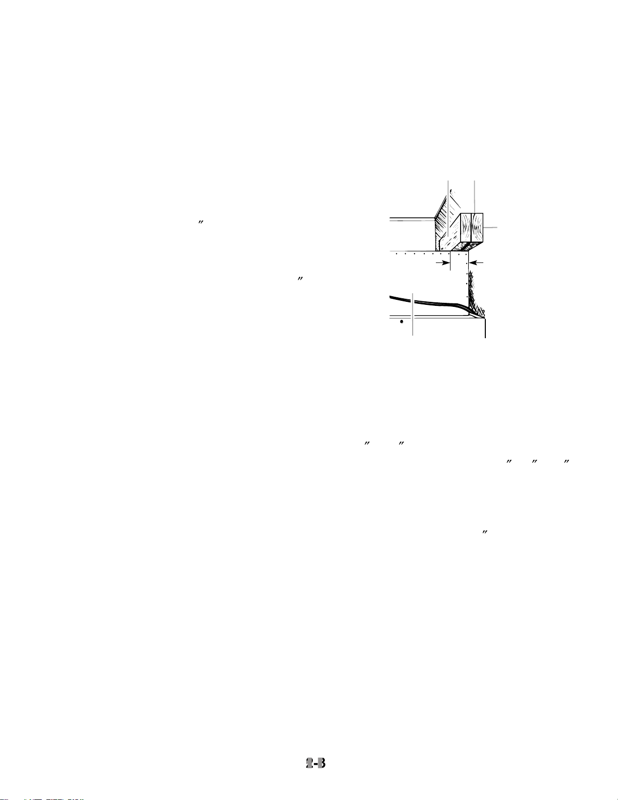
ANTI-TIP BOARDS
• The solid soffit must be within 1
″
soffit is higher than 1
available, prevent the refrigerator from tip-
• It is recommended that the boards be in-
stalled before the refrigerator is installed.
• Boards must be long enough to fully cover
the width of the compressor cover.
21
r
To Install The Anti-Tip Boards:
80
to 90
(203 - 229 cm) above the floor.
2. Securely attach one or two 2
x 4
x 32
wall studs behind the refrigerator. Use six
#8 x 3
″
The wood screws must be screwed into
the studs at least 1-1/2
(3.8 cm). The
• Locate the boards so the bottom surface of
the boards are 84
″
• During installation, raise the refrigerator up
so there is 1/4
″
the top of the refrigerator and the bottom of
the anti-tip boards. Do not crush the con-
denser cover when raising the rear leveling
www.Appliantology.org
2-3
2-3
3
2" (5 cm)
4
1. Center board 1/4" (6 mm) max. above refrigerato
2. Two 2" x 4" x 32" (5 cm x 10 cm x 81 cm) boards
3. Attach to studs with 6-#8 x 3" (7.6 cm) screws
4. Compressor cover
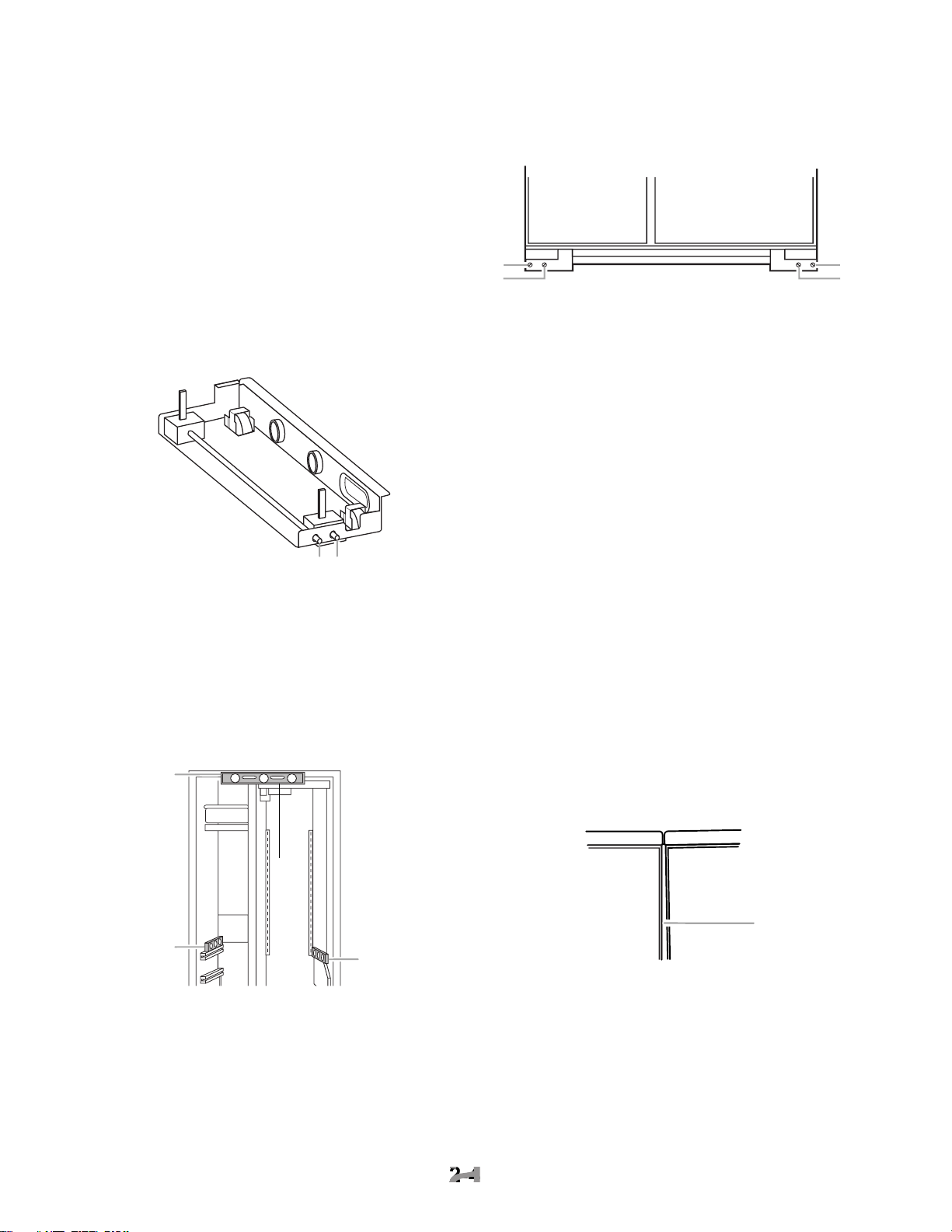
All four leveling legs must contact the floor to
support and stabilize the full weight of the
erator, and not for permanent support.
wise) until the refrigerator weight is supported
To avoid cabinet damage, do not apply more
than 50 in/lbs (58 cm/kg) of torque to the
1. Rear leveling legs
the refrigerator frame. Check to see if the
2. Use the leveling bolts to adjust the leveling
to right.
3. Place a level on the shelves and check to
see if the refrigerator is level from front to
4. Use the leveling bolts to adjust the leveling
to back.
5. Make sure that all four leveling legs con-
tact the floor and support the full weight of
the refrigerator.
6. Make a final check to see that the refrig-
erator is level.
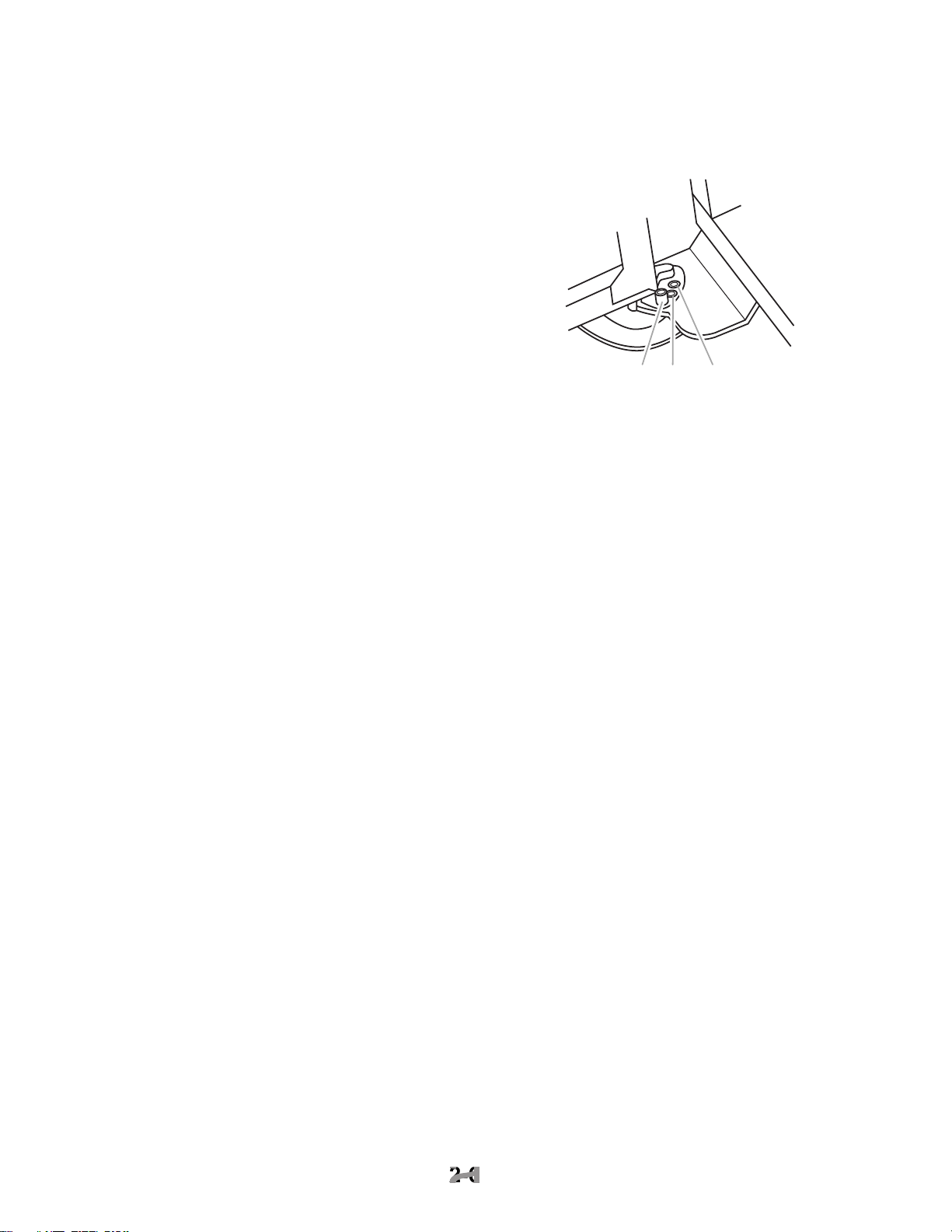
ADJUSTING THE DOORS
alignment to the left, right, in, or out.
the freezer and refrigerator doors. Make
sure that the spacing between the doors is
the same distance at the top and bottom.
2. If the door gap is uneven, the side trim
entire door gasket liner. Remove the six
www.Appliantology.org
2-4
2-4
2. Front leveling legs
1 2
1
2
1. Rear leveling bolt
2. Front leveling bolt
1
2
1
2
1. Level to check left to right leveling
2. Level to check front to back leveling
2
1. Uneven door gap
1
3. Loosen the four 3/8
″
top of both door hinges.
1. Mounting screws
4. Adjust the hinges so that the door gap is
the same distance at the top and bottom.
5. Check the side door gasket gap. Make
sure that the distance is the same at the
top and bottom. Adjust the hinges, as
6. Recheck the front door gap spacing to
even.
7. Tighten the top hinge screws securely.
8. Reinstall the side door trim.
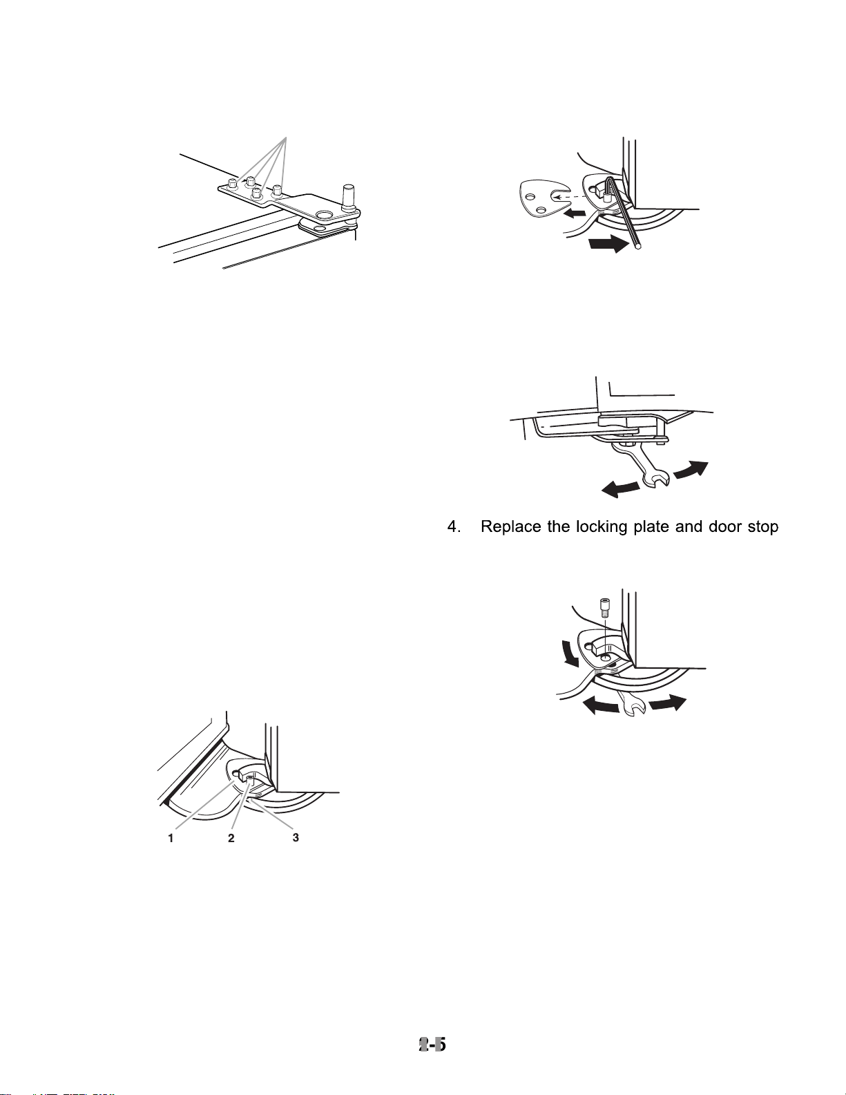
the door.
2. Use an allen wrench and remove the door
stop screw and locking plate from the
3. Use an open-end wrench and turn the
4. Replace the locking plate and door stop
screw. Turn the bushing slightly to align
the hinge and locking plate screw holes.
www.Appliantology.org
2-5
2-5
1
1. Locking plate
2. Door stop screw
3. Bushing
and make sure that they open freely. If a
door opens too wide, remove the door
stop screw from the bottom hinge.
12 3
2. Move the door to the desired open posi-
tion, and then reinstall the door stop screw
at one of the three holes that is closest to
the desired position.
www.Appliantology.org
2-6
2-6
1. Door stoop setscrew (130° position)
°
position.
2. 110
°
position.
3. 90

THEORY OF OPERATION
OVERVIEW
The KitchenAid Built-In Refrigerator Constant
two thermistors to monitor temperature changes
operation of the variable capacity compressor
and a variable position air door. The air door
allows independent temperature control of the
The electronic control seeks the most efficient
controls the operation and speed of the com-
fan speed is used before increasing the com-
tion. A nearly constant run time is sought at the
–9
C to –23
C). Refrigerator tempera-
tures can be set from 46
C to
0
C).
The Adaptive Defrost Control (ADC) portion of
the electronic control utilizes “pulsed defrost”
technology to perform the defrost function (see
THE ELECTRONIC TEMPERATURE CONTROL PANEL
The electronic control monitors the water valve
for total elapsed time and gallons of water
The numeric display can be set for Fahrenheit
or Celsius and displays the actual tempera-
tures. The display range for the refrigerator is
from 27
above or below these limits will be displayed at
the corresponding temperature limit. During
and the refrigerator will read 32
The display will show the temperature setting
any time the actual temperature is within
±
6
of the customer setting. This will prevent con-
cern over temperature fluctuations when the
doors are opened. Press the temperature ad-
justment key to view the current temperature
setting, or to change the setting. When the
temperature adjustment key is used to change
the temperature setting, the display will brighten
for 5 seconds.
Available features include:
• Water Filter Indicator
• Max Cool
• Over-Temperature Alarm
• Holiday Mode
www.Appliantology.org
3-1
3-1
Power
On/Off
Warmer
Colder
FREEZER REFRIGERATOR
°C
SELECT
Warmer
WATER FILTER
RESET
PERCENT LEFT
Colder

Temperature Decreasing
When the freezer temperature begins to de-
crease, the process will reverse. The compres-
sor speed decreases, followed by the evapo-
Temperature Increasing
When the refrigerator calls for cooling while
the freezer is satisfied, the air door begins to
open, and the evaporator fan starts to run at
to rise, the air door will continue to open. If the
temperature continues to rise after the air door
gradually increase to a maximum of 3000 rpm.
Temperature Decreasing
As the refrigerator temperature approaches the
selected setting, the control compares the tem-
which compartment will control the fan speed.
the air door begins to close, thus reducing the
airflow to the refrigerator.
open, and the fan speed begins to decrease.
When the selected temperature setting is
TEMPERATURE CONTROL
The electronic control checks the resistance of
the thermistors, and compares it to both the
customer temperature settings and the last
thermistor reading taken. This information is
operation, and if a change is necessary in the
damper setting, or the evaporator fan or com-
When a warm refrigerator is first put into a
cooling mode, the air door partially opens, and
the compressor and evaporator fan motors
start to run at maximum rpm. The air door will
gradually move to its fully open position.
As the actual temperature in the refrigerator
electronic control compares the temperatures
the speed of the evaporator fan motor.
Temperature Increasing
When the freezer calls for cooling, the com-
chart on page 3-3), and the evaporator fan
and evaporator speeds are continuously up-
dated. Speed changes are made based on:
• The difference between the actual tempera-
ture and the selected temperature settings.
• The rate of temperature change.
selected temperature setting, the evaporator
fan speed begins to gradually increase. The
evaporator fan motor reaches the maximum
speed of 3000 rpm at 5
temperature setting, and the compressor speed
9
www.Appliantology.org
3-2
3-2
The main control board supplies a 5 vdc, peak-
to-peak square wave, at 54 to 150 Hz, to the
three-phase 230 vac. Varying the frequency
to the inverter board, and not the voltage,
changes the speed of the compressor. The
compressor can run at speeds of 1620 to 4500
While the compressor is running, its speed is
continuously updated. Speed is determined
after analyzing two factors:
• The difference between the actual tempera-
ture and the selected temperature settings.
• The rate of temperature change.
freezer’s selected temperature setting, as
shown in the following chart.
The compressor generally cycles on and off
according to the cut-in and cut-out tempera-
tures of the freezer, however, the refrigerator
can turn on the compressor if the evaporator
fan is at maximum speed and the refrigerator
temperatures are not dropping.
To protect the compressor and maintain effi-
ciency, minimum compressor off time is pro-
grammed into the control. When the compres-
sor turns off, a minimum of 7 minutes must
elapse before allowing a restart.
The inverter board utilizes a current limiting
device and thermal protection that eliminates
the need for a compressor mounted thermal
The evaporator fan motor is a 12 vdc, variable
speed motor. The motor has four wires:
• A blue wire provides feedback to monitor the
speed of the motor.
• A red wire provides a constant 12 vdc.
• A yellow wire provides a variable voltage of
• A white wire provides a common return.
AIR DOOR DELAY
After defrost, an evaporator fan delay prevents
through the refrigerator, by chilling the evapo-
ter defrost drip time, the compressor starts at
4500 rpm, but the evaporator fan is delayed
for 8 minutes. The air door remains closed for
8 minutes following defrost.
AIR DOOR
The air door is driven by a reversible DC
stepper motor. The motor operates on a 12
vdc, peak-to-peak square wave. Voltage is
delivered to the air door in a series of short
voltage reading with a VOM.
Separate windings are used to move the air
door open or closed. The door can be in any
one of 1800 positions from 0 to 90 degrees.
The air door is used to fine-tune the airflow to
the refrigerator.
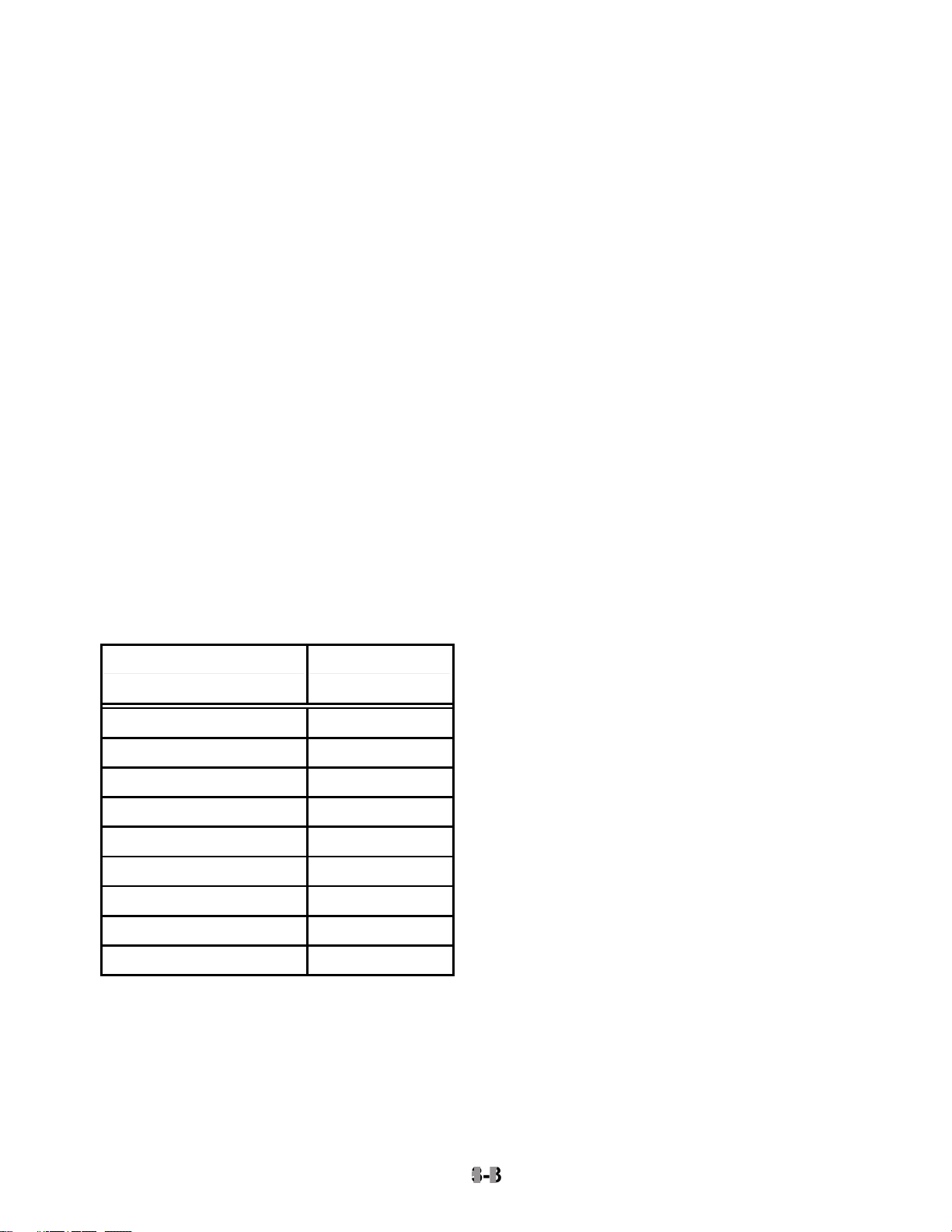
Freezer Temperature Compressor
www.Appliantology.org
3-3
3-3
Setting (°°°°F)
Minimum Speed
9 to –2 1620 rpm
–3 1800 rpm
– 4 2000 rpm
–5 2200 rpm
–6 2400 rpm
–7 2600 rpm
–8 2800 rpm
–9 3000 rpm
–10 3200 rpm

The refrigerator temperature determines the
opening of the air door. When the refrigerator
already running for the freezer, the air door
While the refrigerator is cooling, the door will
cover refrigerator temperature.
ADAPTIVE DEFROST
The adaptive defrost control allows the unit to
enter a defrost mode only when it is needed.
When powered up for the first time, the control
defrost heating time and compressor run time,
the control will continuously adapt the time
and 100+ hours.
defrost.
on continuously. It will then cycle off for 1
will continue to cycle at this ratio until the
At this point, heat is discontinued, and a
4-minute “drip time” begins. This allows the
water to drain before the unit returns to a
cooling mode. Maximum defrost time, (pulsed
When entering a defrost cycle, if the bimetal is
open, the time to defrost is reset to 8 hours, and
the control will time through the entire 37 minute
defrost period. During diagnostics this will al-
tion, and if necessary, bypass the bimetal.
After a power interruption, the following events
will occur:
• The unit returns to the same operating mode
and settings in use prior to the power inter-
• Initially, the compressor, evaporator fan, and
condenser fan motors will be off.
• The air door will close, and then adjust to the
when the air door opens.
• The adaptive defrost control resets the com-
freezer is above 20
set to 8 hours.
• If the freezer temperature is below 12
compressor starts after a delay of 7 minutes.
compressor starts immediately.
the control uses one of the following default
corrected.
thermistor, the air door and the evaporator fan
off cycle, based on current selected tempera-
ture settings. The evaporator fan motor will run
when the air door is open.
At mid-settings of 37
open for 16 minutes, and close for 30 minutes.
Setting the freezer colder, or the refrigerator
warmer, will reduce the door-open time. Set-
ting the freezer warmer, or the refrigerator
colder, will increase the door-open time.
www.Appliantology.org
3-4
3-4

off cycle. The cycle time is based on current
selected temperature settings.
At mid-settings of 37
C, the compressor
and the evaporator fan motors will run for 35
freezer colder will increase the run time. Set-
ting the freezer warmer will decrease the run
time.
The compressor will run at minimum speed.
The evaporator fan will also run at minimum
speed, unless the refrigerator compartment
working, it reverts to the default temperature
settings of 37
the freezer.
compressor will run at 4500 rpm for an indefi-
The “Call Service Alarm” will sound until the
failure has been corrected.
THERMAL SHUTOFF
The electronic control utilizes an on-board ther-
C). When the
temperature drops to 130
C), the com-
continues indefinitely until the cause of the high
temperature has been corrected.
the alarm sounds.
ture setting to 32
C) and the freezer to
–10
C) for 24 hours. During Max Cool,
the freezer and refrigerator temperature dis-
the actual temperatures.
than 1 hour. The control returns to the previous
temperature settings are changed.
AUTOMATIC MAX ICE
Automatic Max Ice operates any time the ice
of Automatic Max Ice is 1-1/2 hours. During
Automatic Max Ice the following occurs:
• The freezer display shows the user tempera-
ture settings and not the actual temperature.
• The freezer temperature setting changes to
–9
C).
• The evaporator fan runs at 3000 rpm.
• The compressor runs the entire 1-1/2 hour
ence between actual freezer temperature
and -9
C).
The Holiday Mode may be used for the follow-
• On vacation.
• Religious observance (Sabbath Mode).
When the Holiday Mode is selected, the corre-
sponding green LED flashes for 2 seconds,
and then remains on, to indicate that the fea-
ture is activated.
www.Appliantology.org
3-5
3-5
 Loading...