

KitchenAid KSGG700ESS2 Installation Guide

INSTALLATION INSTRUCTIONS
30" (76.2 CM) SLIDE-IN GAS RANGES
INSTRUCTIONS POUR L’INSTALLATION DES
CUISINIÈRES À GAZ ENCASTRABLES DE 30"
(76,2 CM)
Table of Contents Table des matières
RANGE SAFETY .............................................................................2
INSTALLATION REQUIREMENTS .................................................4
Tools and Parts .............................................................................4
Location Requirements ................................................................4
Electrical Requirements ...............................................................7
Gas Supply Requirements ...........................................................7
INSTALLATION INSTRUCTIONS ...................................................9
Unpack Range..............................................................................9
Install Anti-Tip Bracket .................................................................9
Adjust Leveling Legs ..................................................................10
Level Range ................................................................................11
Make Gas Connection ...............................................................11
Verify Anti-Tip Bracket Is Installed and Engaged ......................13
Electronic Ignition System .........................................................13
Remove/Replace Drawer ...........................................................14
Oven Door ..................................................................................14
Complete Installation .................................................................15
GAS CONVERSIONS ....................................................................16
Propane Gas Conversion ...........................................................16
Natural Gas Conversion .............................................................19
Adjust Flame Height ...................................................................22
SÉCURITÉ DE LA CUISINIÈRE ...................................................24
EXIGENCES D’INSTALLATION ...................................................26
Outils et pièces ...........................................................................26
Exigences d’emplacement .........................................................26
Spécications électriques ..........................................................29
Spécications de l’alimentation en gaz .....................................29
INSTRUCTIONS D’INSTALLATION .............................................31
Déballage de la cuisinière ..........................................................31
Installation de la bride antibasculement ....................................31
Réglage des pieds de nivellement .............................................32
Réglage de l’aplomb de la cuisinière .........................................33
Raccordement au gaz ................................................................33
Vérier que la bride antibasculement
est bien installée et engagée .....................................................35
Système d’allumage électronique..............................................36
Dépose et réinstallation du tiroir ................................................37
Porte du four ..............................................................................37
Achever l’installation ..................................................................38
CONVERSIONS POUR CHANGEMENT DE GAZ ......................39
Conversion pour l’alimentation au propane ..............................39
Conversion pour l’alimentation au gaz naturel ..........................43
Réglage de la taille des ammes ...............................................46
IMPORTANT:
Installer: Leave installation instructions with the homeowner.
Homeowner: Keep installation instructions for future reference.
IMPORTANT :
Installateur : Remettre les instructions d’installation au propriétaire.
Propriétaire : Conserver les instructions d’installation pour référence ultérieure.
W11398805A
RANGE SAFETY
Your safety and the safety of others are very important.
We have provided many important safety messages in this manual and on your appliance. Always read and obey all safety
messages.
This is the safety alert symbol.
This symbol alerts you to potential hazards that can kill or hurt you and others.
All safety messages will follow the safety alert symbol and either the word “DANGER” or “WARNING.”
These words mean:
You can be killed or seriously injured if you don't immediately
DANGER
WARNING
All safety messages will tell you what the potential hazard is, tell you how to reduce the chance of injury, and tell you what can
happen if the instructions are not followed.
WARNING: If the information in these instructions is not followed exactly, a fire or
explosion may result causing property damage, personal injury or death.
follow instructions.
You
can be killed or seriously injured if you don't
instructions.
follow
– Do not store or use gasoline or other flammable vapors and liquids in the vicinity of this
or any other appliance.
– WHAT TO DO IF YOU SMELL GAS:
Do not try to light any appliance.
•
Do not touch any electrical switch.
•
Do not use any phone in your building.
•
Immediately call your gas supplier from a neighbor's phone. Follow the gas supplier's
•
instructions.
If you cannot reach your gas supplier, call the fire department.
•
– Installation and service must be performed by a qualified installer, service agency or
the gas supplier.
WARNING: Gas leaks cannot always be detected by smell.
Gas suppliers recommend that you use a gas detector approved by UL or CSA.
For more information, contact your gas supplier.
If a gas leak is detected, follow the “What to do if you smell gas” instructions.
IMPORTANT: Do not install a ventilation system that blows air downward toward this gas cooking appliance. This type of
ventilation system may cause ignition and combustion problems with this gas cooking appliance resulting in personal injury or
unintended operation.
2
In the State of Massachusetts, the following installation instructions apply:
Installations and repairs must be performed by a qualified or licensed contractor, plumber, or gasfitter qualified or licensed by
the State of Massachusetts.
Acceptable Shut-off Devices: Gas Cocks and Ball Valves installed for use shall be listed.
A flexible gas connector, when used,must not exceed 4 feet (121.9 cm).
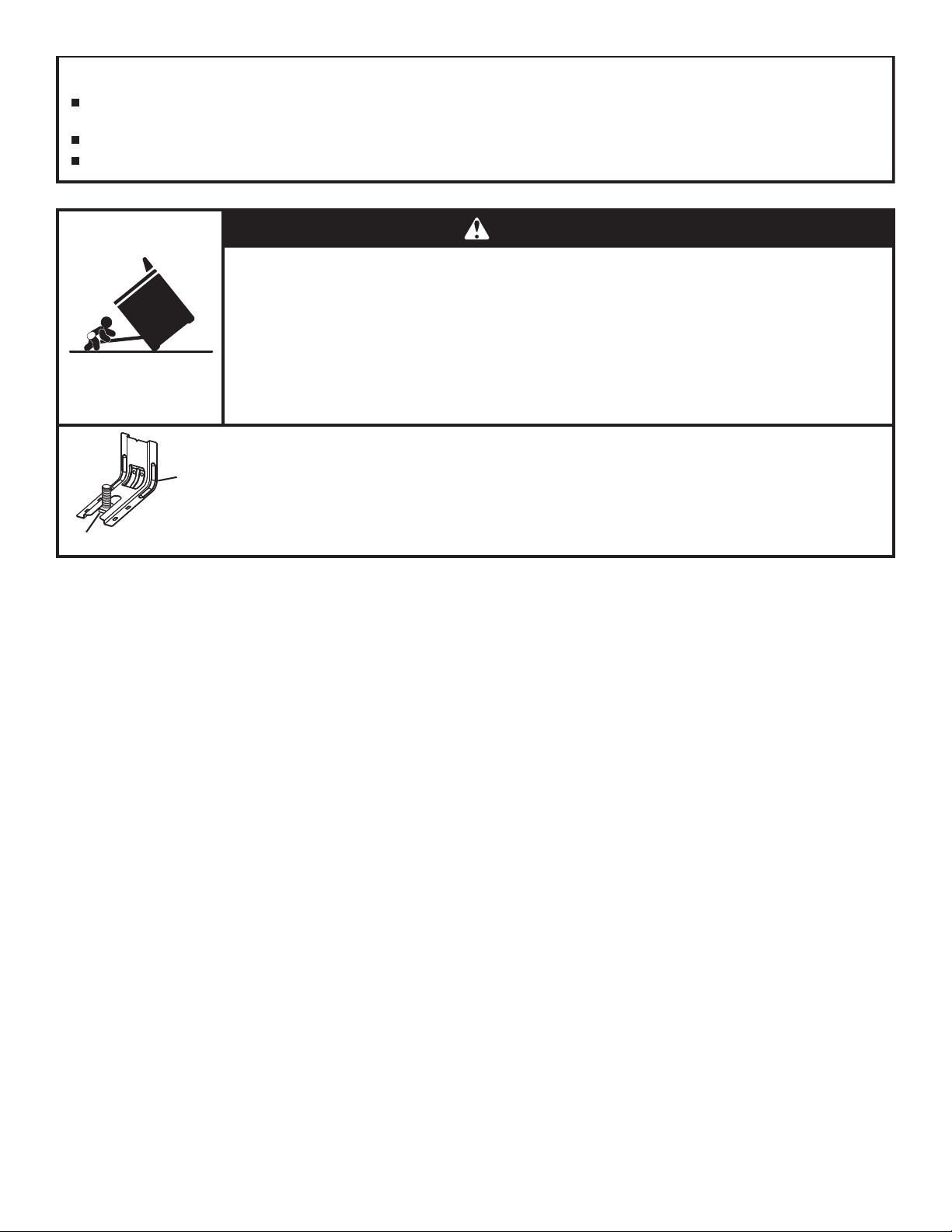
WARNING
Tip Over Hazard
A child or adult can tip the range and be killed.
Install anti-tip bracket to floor or wall per installation instructions.
Slide range back so rear range foot is engaged in the slot of the anti-tip bracket.
Re-engage anti-tip bracket if range is moved.
Do not operate range without anti-tip bracket installed and engaged.
Failure to follow these instructions can result in death or serious burns to children and adults.
To verify the anti-tip bracket is installed and engaged:
Anti-Tip
Bracket
Range Foot
• Slide range forward.
• Look for the anti-tip bracket securely attached to floor or wall.
• Slide range back so rear range foot is under anti-tip bracket.
• See installation instructions for details.
3

INSTALLATION REQUIREMENTS
Tools and Parts
Gather the required tools and parts before starting installation.
Read and follow the instructions provided with any tools
listed here.
Tools Needed
■ Tape measure
■ Phillips screwdriver
■ Flat-blade screwdriver
■ 1/8" (3.2 mm) at-blade
screwdriver
■ Level
■ Drill
■ Wrench or pliers
■ Pipe wrench
■ 15/16" (2.4 cm)
combination wrench
■ 1/8" (3.2 mm) drill bit
(for wood oors)
■ Marker or pencil
Parts Supplied
Check that all parts are included.
■ Propane/Natural Gas Conversion Kit
■ #10 x 1
■ Anti-tip bracket (inside oven cavity)
5
/8" (4.1 cm) screws (for mounting anti-tip bracket) (2)
Anti-tip bracket must be securely mounted to the back wall
or oor. Thickness of ooring may require longer screws to
anchor bracket to suboor. Longer screws are available from
your local hardware store.
Parts Needed
Check local codes and consult gas supplier. Check existing gas
supply and electrical supply. See “Electrical Requirements” and
“Gas Supply Requirements” sections.
IMPORTANT: When the range is used under microwave models:
JMC82808CB-0, JMV9196CB-0, or YJMV9196CB-0, the Door
Bafe Plate Part Number W10737014 must be ordered and
used. Please reference the “Accessories” section of the User
Guide for contact information.
■ Pipe-joint compound
resistant to propane gas
■ 3/16" (4.8 mm)
carbide-tipped masonry
drill bit (for concrete/
ceramic oors)
■ Noncorrosive leak-
detection solution
For propane/Natural Gas
Conversions
■ 5/8" (1.6 cm) combination
wrench
■ 3/8" (1 cm) nut driver
■ 9/32" (7.1 mm) nut driver
■ Masking tape
■ Optional Parts
To purchase these or any other accessories, please reference the
“Accessories” section of the User Guide for contact information.
■ Side Trim Kits:
5/8" (1.6 cm) White - Order Part Number W10675027
5/8" (1.6 cm) Black - Order Part Number W10675026
5/8" (1.6 cm) Stainless Steel - Order Part Number
W10675028
1
1
/8" (2.9 cm) White - Order Part Number W10731885
1
1
/8" (2.9 cm) Black - Order Part Number W10731886
1
1
/8" (2.9 cm) Stainless Steel - Order Part Number
W10731887
■ Backsplash Kits:
High 6" (15.2 cm) White - Order Part Number W10655448
High 6" (15.2 cm) Black - Order Part Number W10655449
High 6" (15.2 cm) Stainless Steel - Order Part Number
W10655450
Location Requirements
IMPORTANT: Observe all governing codes and ordinances.
Do not obstruct ow of combustion and ventilation air.
■ It is the installer’s responsibility to comply with installation
clearances specied on the model/serial/rating plate. The
model/serial/rating plate is located behind the oven door on
the top right-hand side of the oven frame.
■ The range should be located for convenient use in the
kitchen.
■ Recessed installations must provide complete enclosure of
the sides and rear of the range.
■ All openings in the wall or oor where range is to be installed
must be sealed.
■ Cabinet opening dimensions that are shown must be used.
Given dimensions are minimum clearances.
■ The anti-tip bracket must be installed. To install the anti-tip
bracket shipped with the range, see “Install Anti-Tip Bracket”
section.
■ Grounded electrical supply is required. See “Electrical
Requirements” section.
■ Proper gas supply connection must be available. See “Gas
Supply Requirements” section.
■ Contact a qualied oor covering installer to check that the
oor covering can withstand at least 200°F (93°C).
■ Use an insulated pad or 1/4" (6.4 mm) plywood under range
if installing range over carpeting.
IMPORTANT: To avoid damage to your cabinets, check with
your builder or cabinet supplier to make sure that the materials
used will not discolor, delaminate or sustain other damage. This
oven has been designed in accordance with the requirements
of UL and CSA International and complies with the maximum
allowable wood cabinet temperatures of 194°F (90°C).
4
Mobile Home - Additional Installation Requirements
The installation of this range must conform to the Manufactured
Home Construction and Safety Standard, Title 24 CFR,
Part 3280 (formerly the Federal Standard for Mobile Home
Construction and Safety, Title 24, HUD Part 280). When such
standard is not applicable, use the Standard for Manufactured
Home Installations, ANSI A225.1/NFPA 501A or with local codes.
In Canada, the installation of this range must conform with the
current standards CAN/CSA-A240-latest edition, or with local
codes.
Mobile Home Installations Require:
■ When this range is installed in a mobile home, it must be
secured to the oor during transit. Any method of securing
the range is adequate as long as it conforms to the
standards listed above.
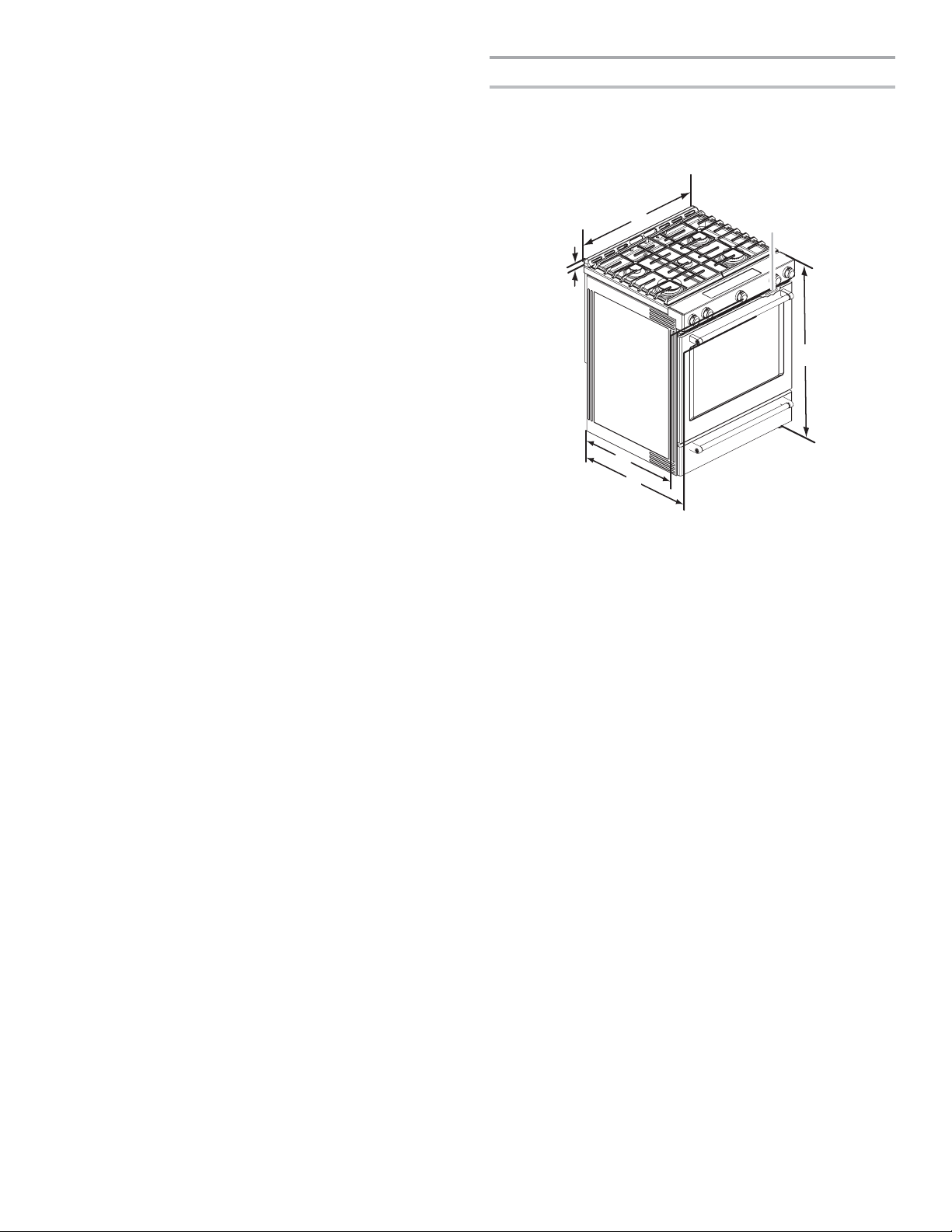
Product Dimensions
This manual covers several models. Your model may appear
different from the models depicted. Dimensions given are
maximum dimensions across all models.
Model KSGB900
B
A
E
F
C
D
A. 1
³⁄₁₆
" (3.0 cm) height from cooktop
to top of vent
B. 29
⁷⁄₈
" (75.9 cm)
C. Model/serial/rating plate (located
behind the oven door on the top
right-hand side of the oven frame)
D. 36" (91.4 cm) height to top of
cooktop edge with leveling legs
screwed in all the way*
E. 28
⁵⁄₁₆
" (71.9 cm) max. depth
from front of console to
back of range
⁷⁄₈
" (73.3 cm) max. depth
F. 2 8
from handle to back of
range
IMPORTANT: Range must be level after installation. Follow the
instructions in the “Level Range” section. Using the cooktop as a
reference for leveling the range is not recommended.
*Range can be raised approximately 1" (2.5 cm) by adjusting the
leveling legs.
5
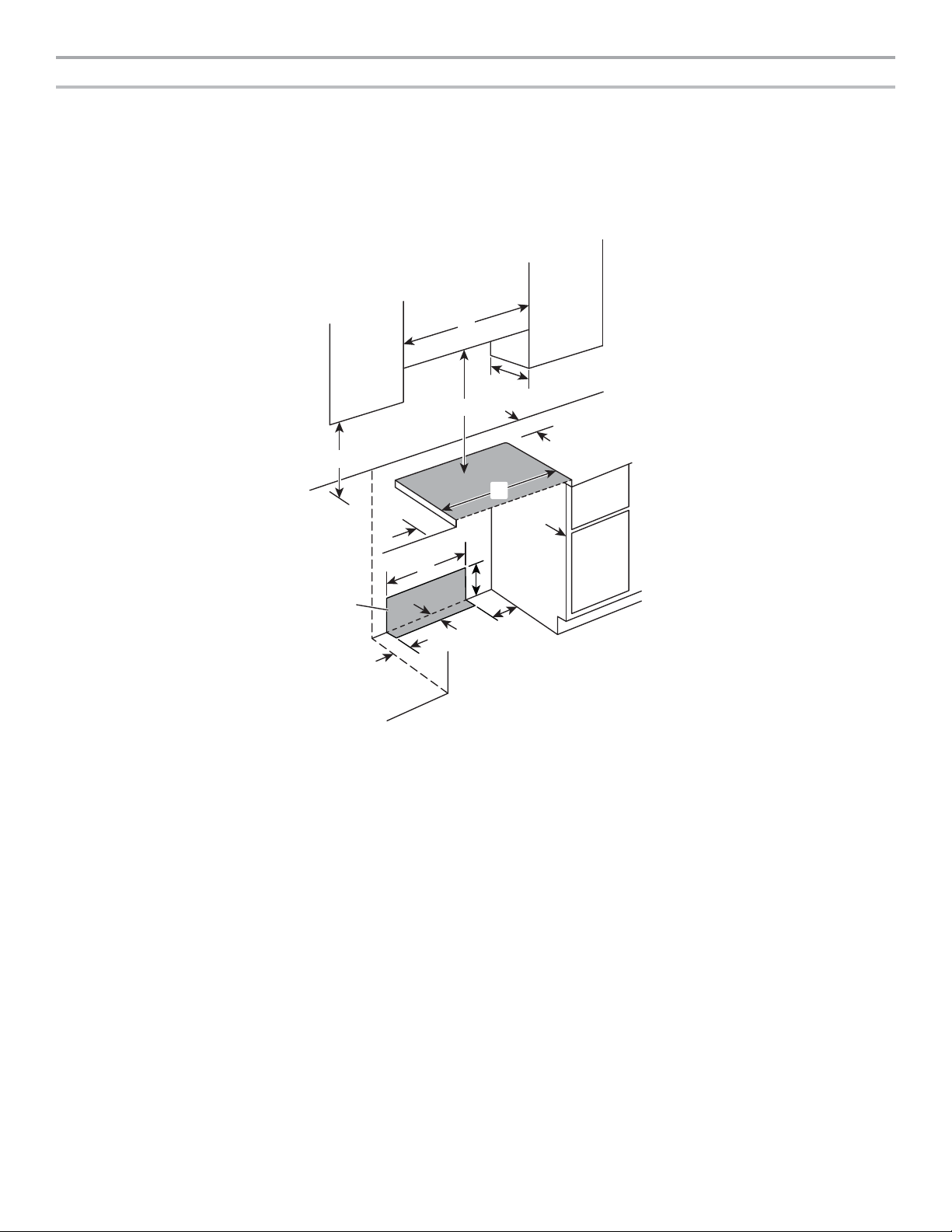
Cabinet Dimensions
Cabinet opening dimensions shown are for 25" (64.0 cm) countertop depth, 24" (61.0 cm) base cabinet depth and 36" (91.4 cm)
countertop height.
IMPORTANT: If installing a range hood or microwave hood combination above the cooking surface, follow the range hood or
microwave hood combination installation instructions for dimensional clearances above the cooktop surface.
Range may be installed next to combustible walls with zero clearance.
NOTE: When installed in a slide-in cutout, the front of oven door may protrude beyond the base cabinet.
Slide-in Cutout
C
B
D
N
A
E
M
F
H
G
I
L
K
J
A. 18" (45.7 cm) upper side cabinet to countertop
B. 13" (33 cm) max. upper cabinet depth
C. 30" (76.2 cm) min. opening width
D. For minimum clearance to top of cooktop, see NOTE*.
E. 30" (76.2 cm) min. opening width
F. 5" (12.7 cm) min. clearance from both sides of range to side wall
or other combustible material
G. The shaded area is recommended for installation of rigid gas pipe
and grounded outlet.
1
/8" (33.3 cm)
H. 13
I. 7¹¹⁄
16" (19.5 cm)
J. 4¹³⁄16" (12.2 cm)
K. 3¹¹⁄16" (9.4 cm) plus measurement of N
L. 12" (30.5 cm)
M. Cabinet door or hinges should not extend into the cutout.
N. Remaining counter depth should not exceed 2¼" (5.7 cm).
*NOTE: 24" (61.0 cm) minimum when bottom of wood or metal cabinet is shielded by not less than 1/4" (6.4 mm) ame retardant
millboard covered with not less than No. 28 MSG sheet steel, 0.015" (0.4 mm) stainless steel, 0.024" (0.6 mm) aluminum or 0.020"
(0.5 mm) copper.
30" (76.2 cm) minimum clearance between the top of the cooking platform and the bottom of an uncovered wood or metal cabinet.
6
Electrical Requirements
Gas Supply Requirements
WARNING
Electrical Shock Hazard
Plug into a grounded 3 prong outlet.
Do not remove ground prong.
Do not use an adapter.
Do not use an extension cord.
Failure to follow these instructions can result in death,
fire, or electrical shock.
IMPORTANT: The range must be electrically grounded in
accordance with local codes and ordinances, or in the absence
of local codes, with the National Electrical Code, ANSI/NFPA 70
or Canadian Electrical Code, CSA C22.1.
This range is equipped with an electronic ignition system that will
not operate properly if plugged into an outlet that is not properly
polarized.
If codes permit and a separate ground wire is used, it is
recommended that a qualied electrical installer determine that
the ground path is adequate.
A copy of the above code standards can be obtained from:
National Fire Protection Association
1 Batterymarch Park
Quincy, MA 02169-7471
CSA International
8501 East Pleasant Valley Road
Cleveland, OH 44131-5575
■ A 120 V, 60 Hz, AC only, 15 A fused, ground and polarized
electrical circuit is required. A time-delay fuse or circuit
breaker is also recommended. It is recommended that a
separate circuit serving only this range be provided.
■ Electronic ignition systems operate within wide voltage limits,
but proper grounding and polarity are necessary. Check that
the outlet provides 120 V power and is correctly grounded.
■ This gas range is not required to be plugged into a GFCI
(Ground-Fault Circuit Interrupter) outlet. It is recommended
that you not plug an electric spark ignition gas range or any
other major appliance into a GFCI wall outlet as it may cause
the GFCI to trip during normal cycling.
■ Performance of this range will not be affected if operated
on a GFCI-protected circuit. However, occasional nuisance
tripping of the GFCI breaker is possible due to the normal
operating nature of electronic gas ranges.
■ The tech sheet and wiring diagram are located on the back
of the range in a plastic bag.
NOTE: The metal chassis of the range must be grounded in
order for the control panel to work. If the metal chassis of the
range is not grounded, no keypads will operate. Check with
a qualied electrician if you are in doubt as to whether the
metal chassis of the range is grounded.
WARNING
Explosion Hazard
Use a new CSA International approved gas supply line.
Install a shut-off valve.
Securely tighten all gas connections.
If connected to propane, have a qualified person make
sure gas pressure does not exceed 14" (36 cm) water
column.
Examples of a qualified person include:
licensed heating personnel,
authorized gas company personnel, and
authorized service personnel.
Failure to do so can result in death, explosion, or fire.
Observe all governing codes and ordinances.
IMPORTANT: This installation must conform with all local codes
and ordinances. In the absence of local codes, installation must
conform with American National Standard, National Fuel Gas
Code ANSI Z223.1 - latest edition or CAN/CGA B149 -
latest edition.
IMPORTANT: Leak testing of the range must be conducted
according to the manufacturer’s instructions.
Type of Gas
Natural Gas:
■ This range is factory set for use with Natural gas. See “Gas
Conversions” section. The model/serial/rating plate located
on the oven frame behind the top right-hand side of the oven
door has information on the types of gas that can be used. If
the types of gas listed do not include the type of gas available,
check with the local gas supplier.
Propane Gas Conversion:
Conversion must be done by a qualied service technician.
No attempt shall be made to convert the appliance from the gas
specied on the model/serial/rating plate for use with a different
gas without consulting the serving gas supplier. See “Gas
Conversions” section.
Gas Supply Line
■ Provide a gas supply line of 3/4" (1.9 cm) rigid pipe to the
range location. A smaller size pipe on longer runs may
result in insufcient gas supply. With propane gas, piping or
tubing size can be 1/2" (1.3 cm) minimum. Usually, propane
gas suppliers determine the size and materials used in the
system.
NOTE: Pipe-joint compounds that resist the action of
propane gas must be used. Do not use TEFLON
®†
tape.
†®TEFLON is a registered trademark of Chemours.
7
Flexible Metal Appliance Connector:
■ If local codes permit, a new CSA design-certied, 4 to
5ft (122 to 152.4 cm) long, 1/2" or 3/4" (1.3 or 1.9 cm)
I.D. (inside diameter), exible metal appliance connector
may be used for connecting range to the gas supply line.
■ A 1/2" (1.3 cm) male pipe thread is needed for
connection to the female pipe threads of the inlet to the
appliance pressure regulator.
■ Do not kink or damage the exible metal tubing when
moving the range.
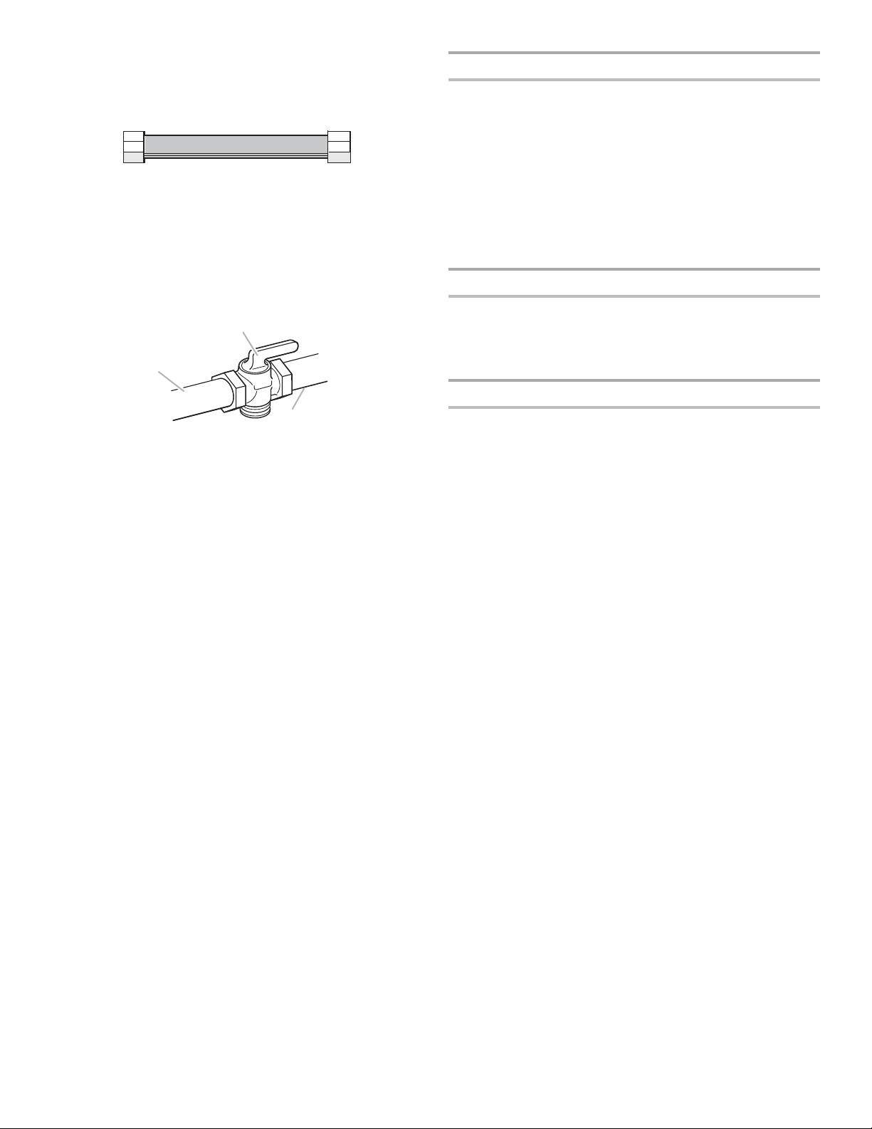
■ Must include a shut-off valve:
Install a manual gas line shut-off valve in an easily accessible
location. Do not block access to shut-off valve. The valve is
for turning on or shutting off gas to the range.
B
A
C
A. Gas supply line
B. Shut-off valve “open” position
C. To range
Gas Pressure Regulator
The gas pressure regulator supplied with this range must be
used. The inlet pressure to the regulator should be as follows
for proper operation:
Natural Gas:
Minimum pressure: 5" (12.7 cm) WCP
Maximum pressure: 14" (35.5 cm) WCP
Propane Gas:
Minimum pressure: 11" (28 cm) WCP
Maximum pressure: 14" (35.5 cm) WCP
Contact local gas supplier if you are not sure about the inlet
pressure.
Burner Input Requirements
Input ratings shown on the model/serial/rating plate are for
elevations up to 2,000 ft (609.6 m).
For elevations above 2,000 ft (609.6 m), ratings are reduced at
a rate of 4% for each 1,000 ft (304.8 m) above sea level (not
applicable for Canada).
Gas Supply Pressure Testing
Gas supply pressure for testing regulator must be at least 1"
water column pressure above the manifold pressure shown on
the model/serial/rating plate.
Line pressure testing above 1/2 psi (3.5 kPa)
gauge (14" [35.5 cm] WCP)
The range and its individual shut-off valve must be disconnected
from the gas supply piping system during any pressure testing of
that system at test pressures in excess of 1/2 psi (3.5 kPa).
Line pressure testing at 1/2 psi (3.5 kPa)
gauge (14" [35.5 cm] WCP) or lower
The range must be isolated from the gas supply piping
system by closing its individual manual shut-off valve during
any pressure testing of the gas supply piping system at test
pressures equal to or less than 1/2 psi (3.5 kPa).
8
 Loading...