

KitchenAid KIVD800TOB, KIVD860TOB, KPID850T, KPED890T Installation Instructions,Use And Care Information
KIVDEIOOTOB
30” Plenum
KIVD860TOB
36” Plenum
KPED890T
External Power
KPID850T
Internal Power
30” and 36”
Downdraft
Vent Systems
IMPORTANT:
Read and save these instructions.
Installer: Leave Installation Instructions with the
Homeowner.
Homeowner: Keep Installation Instructions for
luture reference.
Save Installation Instructions for local electrical
inspector’s use
SPECIAL NOTE:
Dimensions and
o:her
Information given are lor
Installations with any KItchenAid cooktop. If installIng
the downdraft venl system with a different brand of
cooktop, consult that manufacturer’s cutout dlmenslons
and lnstailatlon methods and the Information in this
guide
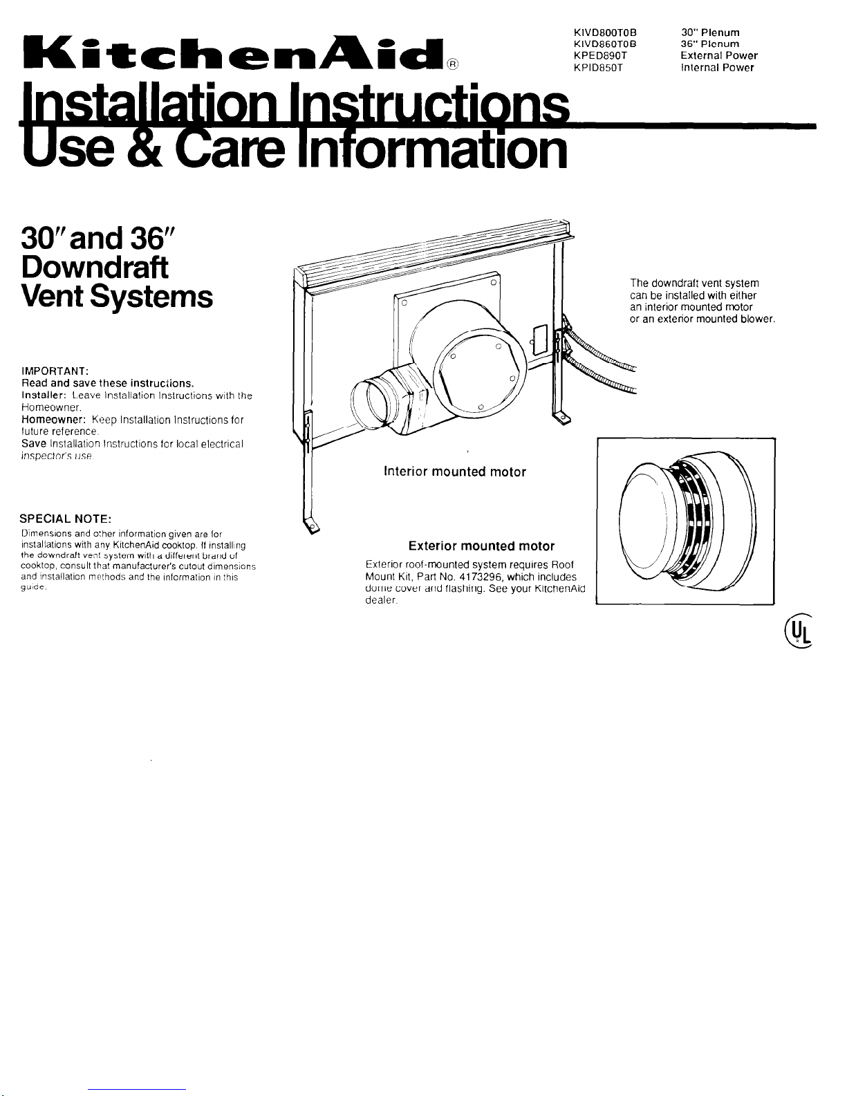
Interior mounted motor
a
Exterior mounted motor
Exterior roof-mounted system requires Roof
Mount Kit, Part No. 4173296, which includes
dome cover and flashing. See your KItchenAid
dealer
The downdraft vent system
can be installed with either
an interior mounted motor
or an exterior mounted blower
C
UL
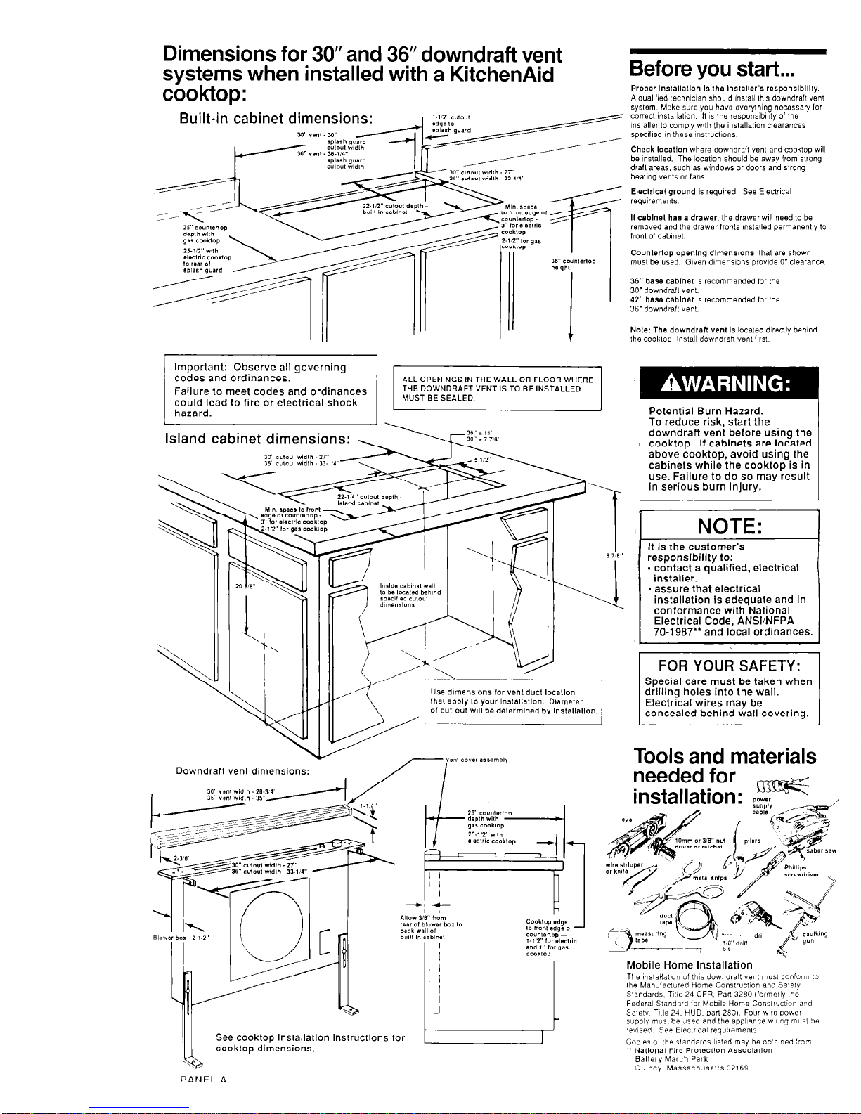
Dimensions for 30” and 36” downdraft vent
systems when installed with a KitchenAid
cooktop:
Before you start...
Proper lnslallatlon IS the Installer’s responslblllly.
A quaIlfled technician should ~nslall Ihis downdraft “en!
system Make sura you have everything necessary lor
corred ~nslallal~on II IS Ihe responslblllly 01 Ihe
mstaller lo comply with Ihe installallon clearances
specllled ,n these ~nslrucl~ons.
Check locatlon where downdrall venl and cooklop WIII
be inslalled. The local~on should be away from slrong
drall areas, such as windows or doors and strong
healing ven,s or lans.
Eleclrlcal ground is requred See Eleclr~cal
requiremenls
If cablnel hss a drawer, Ihe drawer WIII need lo be
removed and Ihe drawer lronls lnslalled permanently lo
lronl of cabfnel
Counlerlop openlna dlmenslons lhal are shown
Built-in cabinet dimensions:
y1” *sn, YI” -
36” base cablnel IS recommended lor Ihe
30’downdrafl “en,.
42” be% cablnel IS recommended lor Ihe
36- downdrafl “en,
Note: The downdraft “en, IS located dlrealy behmd
the cookiop lnslall downdraH “en, hrsl
Important: Observe all governing
1 ;;;,I; Ordinances’
ALL OPENINGS IN THE WALL OR FLOOR WHERE
Failure to meet codes and ordinances
THE DOWNDRAFT VENT IS TO BE INSTALLED
e
could lead to fire or electrical shock
1 \l
downdraft vend before using the
Island cabinet dimensions:
30’ CtiO”! Widlh ZT
NOTE:
It is the customer’s
responsibility to:
- contact a qualified, electrical
installer.
- assure that electrical
installation is adequate and in
conformance with National
Electrical Code, ANSVNFPA
70-1987” and local ordinances.
8 7,v
----------I
FOR YOUR SAFETY:
Special care must be taken when
drilling holes into the wall.
Electrical wires may be
concealed behind wall covering.
Use dimensions lor vent duct locatlon
lhal apply lo your Inslallatlon. Diameler
of cut-out will be delermlned by Inslallallon.
J
I
I
Tools and materials
Downdraft vent dimensions:
Mobile Home Installation
The mslaHa11on of IhIs downdraH vanI mus! conlorm lo
Ihe Manufactured Home Conslrucl~on and Salely
Slandarda. TII!B 24 CFR. Parl 3280 (formerly the
Federal Standard for MoblIe Home Conslruct~on a-d
Salely T~!le 24. HUD, parI 280) Four-wre power
supply musl be Jsed and Ihe appliance Waring mu51 Se
,evlsed See E~eclr~cal reqwemenls
Capes 01 ,hs standards l,sled may be ablalned :‘o-,
** National Fire Proleclion Associalion
II,
See cooktop Installation
lnstructlons for
I
cooktop dimensions,
PANEI- A
I
Ballery March Park
O”,ncy. hlassachusells 02169
Electrical
requirements
Venting
requirements
Electrical ground is required on this
appliance.
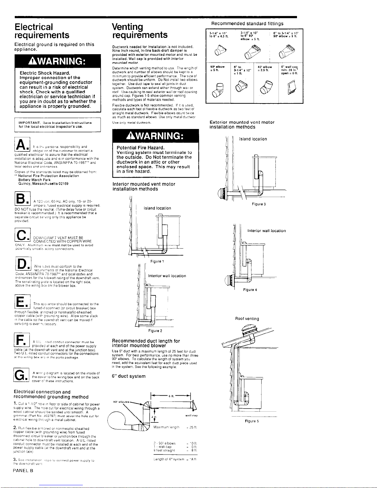
Recommended standard fittings
Ouchvork needed lor lnslallallon Is nol Included.
Nine Inch round, In-line backdraft damper Is
provided wllh exlerlor mounted motor and must be
Inslalled. Wall cap Is provided wllh lnlerlor
mounled motor.
Delermine which venl~ng melhod lo usa Thu leng:h 01
duclwork and number of elbows should be kept 10 a
mmmum lo provide efllcent perlormance The we of
duclwork should be undorm Do Nol inslall Iwo elbows
loqelher Use dud lake lo seal all ,o1n1s or. duel
Electric Shock Hazard.
Improper connection of the
equipment-grounding conductor
can result In a risk of electrical
shock. Check with a qualified
electrician or service technician if
you are in doubt as to whether the
appliance is properly grounded.
sykm Ductwork can extend elth& through wa’~ or
rod Use caulking to seal exierior wall or rcrot open\ng
around cap FIguris l-5 show common wwng
melhods and types of
malerials
needed
Flexible ductwork 1s Not recommended If I( 1s used,
calculale each fool 01 llexlble dudwork as Lwo feet of
slralghl metal ductwork. Flerlble elbows c~unl twce
as much as slandard elbows Use only melal dbclwor
Use onlv melal ductwork
IMPORTANT: !;a,. lnstallallon lnsirucllons
Exterior mounted vent motor
installation methods
11 II
Island locallon
Potential Fire Hazard.
Venting system must terminate to
the outside. Do Not terminate the
ductwork in an attic or other
enclosed space. This may result
in a fire hazard.
Interior mounted vent motor
installation methods
Island locallon
Figure 3
~nslallat~on IS adoq~ate and 1s in conformance wllh the
Nal~onal Eleclrlca, ‘Code. ANSIINFPA 70-1987” and
local mdes and or~!,nances
BaHery March Park
Cluincy, Massachussns 02169
IB
.
A 123 in,, 60 Hz, AC only, 15. or 20.
amper?. iused evxlr1c.3 supply 1s required.
DO NOT IUSB the ~leutral (Time-delay fuse or c1rcu0
breaker 1s recommended, II IS recommended thal a
separale c,rcui, se’v,ng oniy ,h,s appliance be
prov,ded
/c1
. DOW:;bHAFT VENT MUST BE
CONNECTED WITH COPPER WIRE
Code, ANSI/NFPA 70 ,987” and local codes and
o’dlwrces for Ihe k’lowa!, ral,ng 01 Ihe downdrall ye,,,.
The ser~al~ral~no o,aIe 1s located on Ihe riaht side.
lnlerior wall location
1
Flgure 4
1E
.
This +i, lance should be connecled lo the
lused-i! sconrecl (or circu,, breaker] box
Ibroug’l f;ex~ble, ar,nored or nonmelalllc-shealhed.
ccpper cable (wlb grouna ng we) Allow some slack
T Ihs cable so Ihe cowndrah vent can be moved II
sevclng is e”el nL:essar,
Roof venling
Figure 2
1F
A U L . ited cond”,, conneclor mus, be
prov,de> al each end 01 Ihs power supply
cable (al the downdran “en, and a, Ihe unct,on box)
Two U L ~+sled condu:! co,,,,eclors lor 1 e connenions
b
a’ I’le w~r,ng box ari in Ihe parls package
Recommended duct length for
interior mounted blower
Use 6’duct with a maximum lenglh 01 25 feet lo, dud
syslem For besl perlormance, use no more lhan three
90’ elbows. To calculale Ihe length 01 syslem you
need, add the eqwalenl Ieel for each duel piece used
in Ihe syslem. See Ihe lollowlng example
6” duct system
/G
A WIIII j d,agram ,s located on Ihe ,ns,de of
.
Ihe co”dr lo Ihe w,r,ng box and on Ihe back
cover o’ these ~mslrucl~ons
Electrical connection and
recommended grounding method
2. Rbn I~BXID,~ armored or nonme,allIc sheathed
copper cable (wllh grounding we) from fused
dlsconnecl c,rcu~l b,eaker or ,uncl,on box lhrauqh Ihe
cabInsI hole lo dounarall “en, local~on
A U L &led
cond”,t conr,eclor musl be ;nslalled a, each end of Ihe
cower supply cable ,a, :he downdraH venl and a, Ihe
,unc,.on tmxj
Figure 5
2 90. elbows
1 wali cap
8 !eel slra,gh,
Length o’ 6’syslem = ‘8 ,I
PANEL
B
 Loading...