

KitchenAid KICU265HSS, KICU285HSS, KICU265HBT, KICU265HWH Installation Instructions
Installation Instructions and
Use and Care Guide
36" (91.4 cm)
48" (121.9 cm)
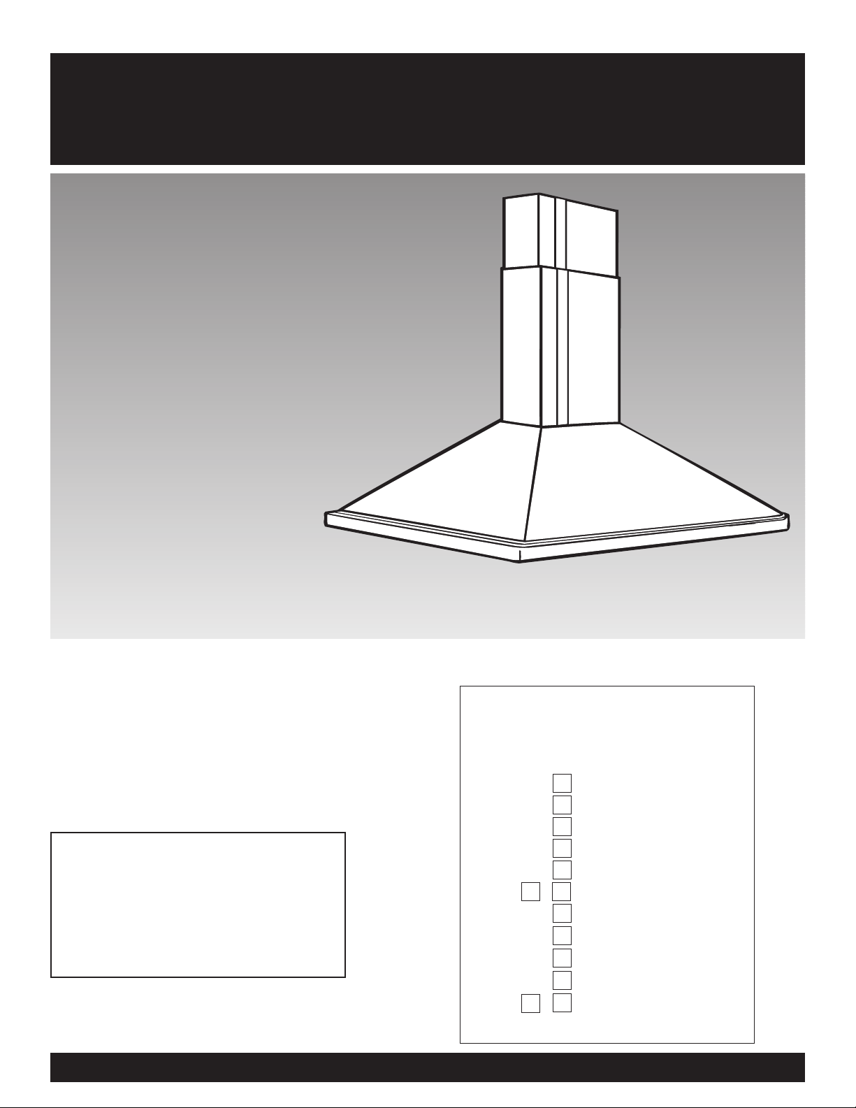
Island Canopy Range Hood
IMPORTANT:
Read and save
these instructions.
IMPORTANT:
Installer: Leave Installation Instructions with
the homeowner.
Homeowner: Keep Installation Instructions for
future reference.
Save Installation Instructions for local electrical
inspector's use.
4329223/9763387
Quick Reference
Table of Contents:
Pages
Before you start
Product dimensions
Cabinet dimensions
Venting requirements
Electrical requirements
Installation steps
Use and Care Information
Wiring diagram
Accessories
Warranty
Requesting Assistance
or Service
2
3
3
3
5
5 - 7
8
9
9
10
11 - 1 2
Before you start...
Proper installation is your
responsibility:
• Have a qualified technician install
this range hood.
• Comply with installation clearances
specified on the model/serial rating
plate.
Model/serial rating plate is located
inside the range hood on the rear
wall.
Island canopy hood location should
be away from strong draft areas, such
as windows, doors and strong heating
vents.
Grounded electrical outlet is required.
See “Electrical requirements.”
Note:The island canopy hood is
factory set for venting through the
roof or wall. For non-vented
(recirculating) installations see “NonVented (Recirculating) Kits” on the
back page.
All openings in ceiling and wall where
range hood will be installed must be
sealed.
Important: Observe all governing
codes and ordinances.
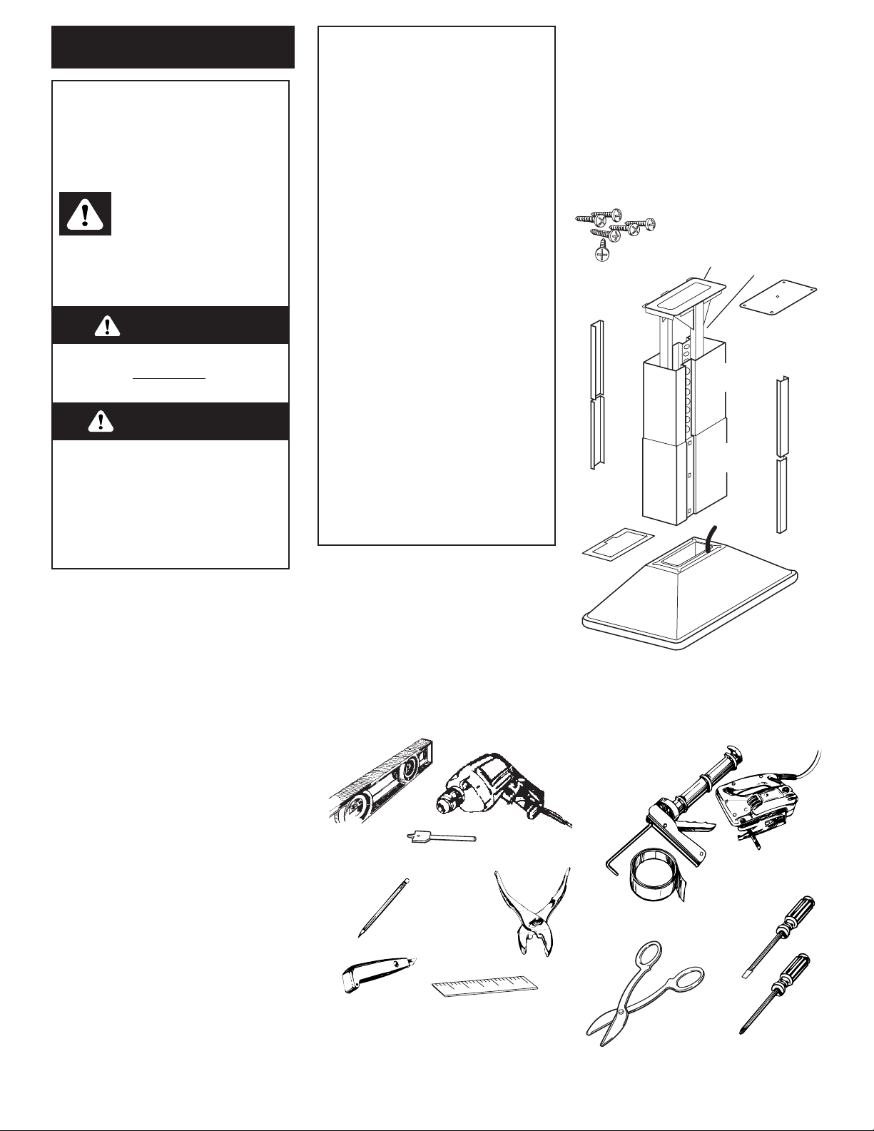
Parts supplied:
6 screws
mounting
template
upper
chimney
trim
support
system
8 trim
clips
support
mounting
bracket
upper
chimney
lower
chimney
trim
upper
chimney
trim
lower
chimney
trim
canopy
damper
lower
chimney
Parts needed:
2 U.L.- or C.S.A.- listed, 1/2" (12.5 mm)
conduit connectors
power supply cable
1 wall or roof cap
metal vent system
allen wrench set
Tools needed:
Phillips
screwdriver
flat-blade
screwdriver
caulking gun and
weatherproof
caulking
compound
duct tape
metal
snips
pliers
pencil
saber or
keyhole saw
drill
1-1/4" drill bit
level
measuring
tape or ruler
wire stripper
or utility knife
WARNING — TO REDUCE THE
RISK OF FIRE, ELECTRIC SHOCK,
OR INJURY TO PERSONS,
OBSERVE THE FOLLOWING:
Installation work and electrical
wiring must be done by qualified
person(s) in accordance with all
applicable Codes and Standards,
including Fire Rated
Construction. The combustion
airflow needed for safe
operation of fuel-burning
equipment may be affected by
this unit’s operation. Follow the
heating equipment
manufacturer’s guideline and
safety standards such as those
published by the National Fire
Protection Association (NFPA),
and the American Society of
Heating, Refrigeration and Air
Conditioning Engineers
(ASHRAE), and the local code
authorities.
When cutting or drilling into wall
or ceiling, do not damage
electrical wiring and other
hidden utilities.
Ducted fans must always be
vented to the outdoors.
WARNING — To reduce the risk
of fire, use only metal ductwork.
This unit must be grounded.
2
This is the safety alert symbol.
This symbol alerts you to
potential hazards that can kill
or hurt you and others. All safety
messages will follow the safety alert
symbol and either the word “DANGER”
or “WARNING”. These words mean:
You can be killed or seriously injured
if you don’t follow instructions.
DANGER
WARNING
Your safety and the safety of
others is very important.
We have provided many important
safety messages in this manual and
on your appliance. Always read and
obey all safety messages.
All safety messages will tell you what
the potential hazard is, tell you how to
reduce the chance of injury, and tell
you what can happen if the
instructions are not followed.
You can be killed or seriously injured
if you don’t immediately
follow
instructions.
3
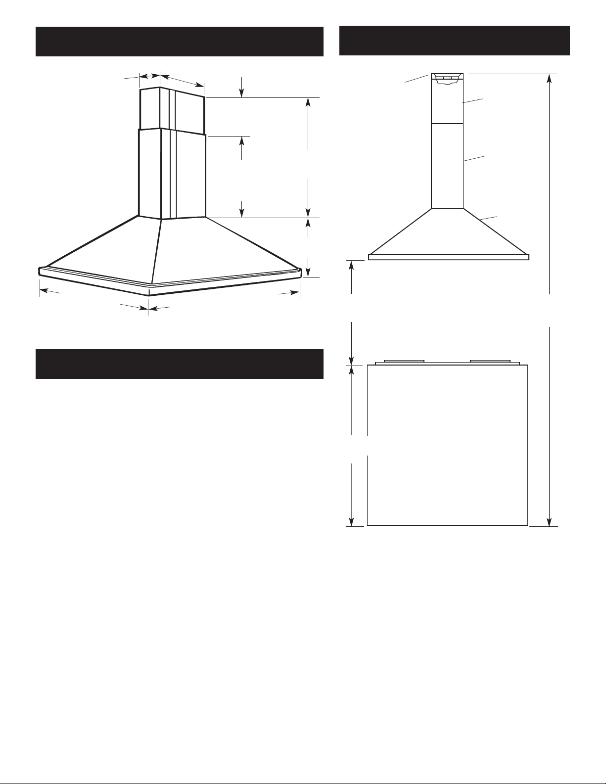
Cabinet dimensions
Product dimensions
8’ (2.4 m) min. 9’ (2.7 m) max.
ceiling to floor
support
structure
24" (61 cm) min.
bottom of canopy
to cooking surface
canopy
lower chimney
upper chimney
Venting requirements
• It is recommended that the range hood be vented vertically through
the roof through 9” (22.9 cm) round metal ventwork.
• The size of the vent should be uniform.
• Use no more than three 90° elbows.
• Make sure there is a minimum of 24" (61 cm) of straight vent
between the elbows if more than one elbow is used.
• Do Not install two elbows together.
• The length of vent system and number of elbows should be kept to
a minimum to provide efficient performance.
• The vent system must have a damper. If roof or wall cap has a
damper, Do Not use damper supplied with the range hood.
• Use duct tape to seal all joints in the vent system.
• Use caulking to seal exterior wall or roof opening around the cap.
Determine which venting method is best for your application and
follow “Preparation” under ”Installation steps“ on Page 5.
For the most efficient and quiet
operation:
Vent system must terminate to the outside.
Do not terminate the vent system in an attic or other enclosed
area.
Do not use 4” (10.2 cm) laundry-type wall caps.
Use metal vent only. Rigid metal vent is recommended. Do not use
plastic or metal foil vent.
36" hood 35-3/8" (89.9 cm) or
48" hood 47-1/4" (120 cm)
overall width
23-5/8" (60 cm)
overall depth
24-5/8" (62.5 cm) min. 34-3/4" (88.3 cm) max.
overall chimney height
23-5/8"
(60 cm)
lower
chimney
height
1" (2.5 cm) min. 11-1/8" (23.8 cm) max.
upper chimney height
10-1/4" (26 cm)
canopy height
36" (91.4 cm)
base cabinet
height
7 1/16"
(17.9 cm)
10 7/8"
(27.6 cm)
4
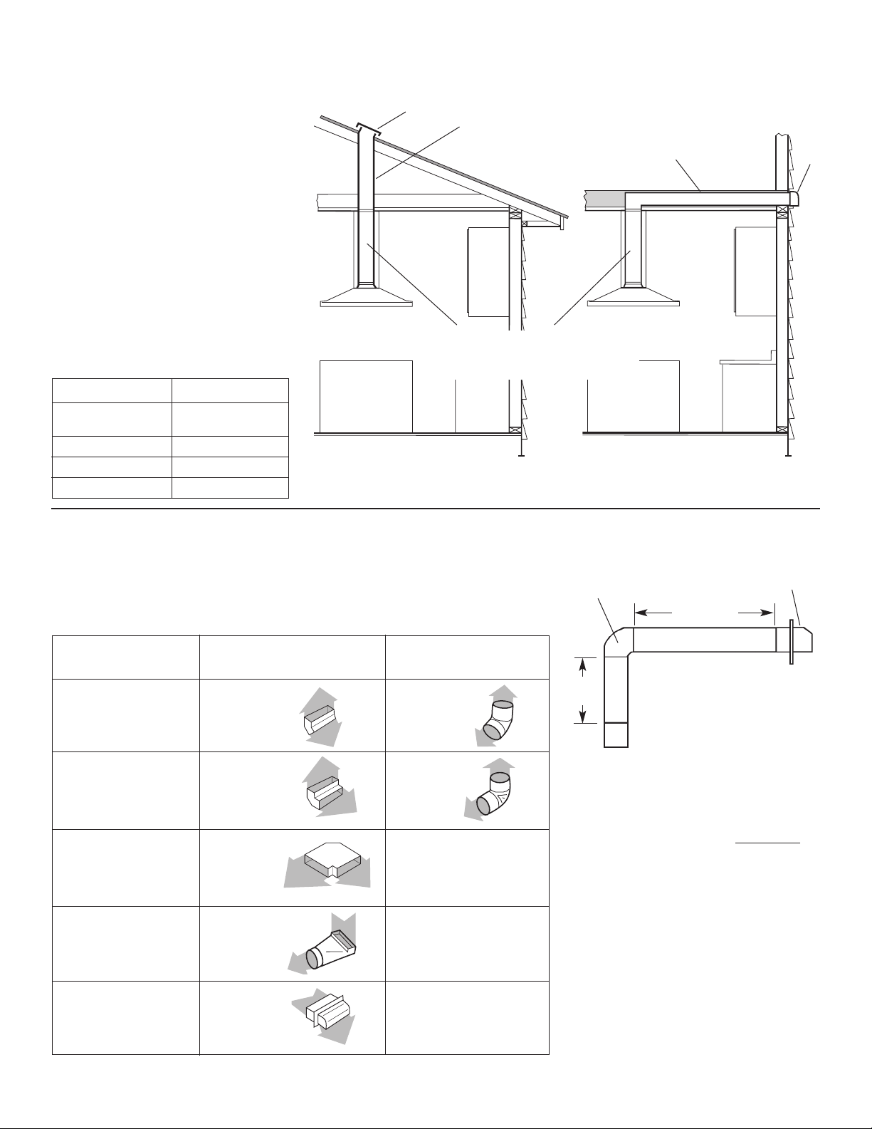
Venting methods
This island canopy range hood is
factory set for venting through the roof
or wall. For non-vented (recirculating)
installations, see “Non-Vented
(Recirculating) Kits” on back page.
Vent system needed for installation is
not included. 3-1/4" x 10" (8.3 cm x
25 cm) rectangular, 7" (17.8 cm) round,
8" (20.3 cm) round or 9" (22.9 cm)
round vent may be used.The hood
exhaust opening is 3-1/4" x 10"
(8.3 cm x 25 cm).
Ventwork can terminate either through
the roof or wall. To vent through a
wall, a 90° elbow is needed.
The vent system length should not
exceed the lengths shown in the chart
below.
Vent size Maximum length
3-1/4" x 10" 35 ft. (10.7 m)
(8.3 cm x 25 cm)
7" (17.8 cm) round 40 ft. (12.2 m)
8" (20.3 cm) round 50 ft. (15.2 m)
9" (22.9 cm) round 60 ft. (18.3 m)
3-1/4" x 10"
(8.3 cm x 25 cm)
through
the roof
roof cap
Horizontal wall venting
3-1/4" x 10"
(8.3 cm x 25 cm)
through the wall
wall
cap
Vertical roof venting
Vent Piece 3-1/4" x 10" (8.3 cm x 25 cm) 7" (17.8 cm), 8" (20.3 cm)
Rectangular or 9" (22.9 cm) Round
45° elbow 7.0 feet 2.5 feet
(2.1 m) (0.8 cm)
90° elbow 5.0 feet 5.0 feet
(1.5 m) (1.5 m)
90° flat elbow 12.0 feet
(3.7 m)
transition to round 5.0 feet
(1.5 m)
wall cap 0.0 feet
(0.0 m)
3-1/4" x 10”
(8.3 cm x 25 cm)
elbow
wall
cap
Maximum length = 35 ft. (10.7 m)
1 — 90° elbow = 5 ft. (1.5 m)
8 ft. (2.4 m) straight = 8 ft. (2.4 m)
1 — wall cap = 0 ft. (0 m)
Length of 3-1/4" x 10"
(8.3 cm x 25 cm)
system = 13 ft. (4 m)
6 ft. (1.8 m)
2 ft.
(0.6 m)
3-1/4" x 10"
(8.3 cm x 25 cm)
v
ent system
To calculate the length of the system
you need, add the equivalent feet for
each vent piece used in the system.
Note: Flexible vent is Not
recommended.
If it is used, each foot of flexible vent
used is equivalent to two feet (61 cm)
of straight metal vent when
calculating the vent system length.
(Example: A flexible elbow equals two
standard elbows.)
Calculating the vent system length
Note: 3-1/4" x 10" (8.3 cm x 25 cm)
rectangular vent must be used inside
chimney cover. Round vent will not fit
inside chimney cover.
5
Electrical requirements
Installation steps
Important: Observe all governing
codes and ordinances.
It is the customer’s responsibility:
• To contact a qualified electrical
installer.
• To assure that the electrical
installation is adequate and in
conformance with National
Electrical Code, ANSI/NFPA 70
— latest edition*, or CSA
Standards C22.1-94, Canadian
Electrical Code, Part 1 and
C22.2 No.0-M91 - latest
edition** and all local codes
and ordinances.
If codes permit and a separate
ground wire is used, it is
recommended that a qualified
electrician determine that the
ground path is adequate.
A 120-volt, 60 Hz, AC-only, fused
electrical supply is required on a
The range hood must be
connected with copper wire only.
The range hood should be
connected directly to the fused
disconnect (or circuit breaker) box
through flexible armored or
nonmetallic sheathed copper cable. A
U.L.- or C.S.A.- listed strain relief must
be provided at each end of the power
separate 15-amp circuit, fused on
both sides of the line.
Do not ground to a gas pipe.
Check with a qualified electrician
if you are not sure range hood is
properly grounded.
Do not have a fuse in the neutral
or ground circuit.
IMPORTANT:
Save Installation Instructions for
electrical inspector’s use.
supply cable. Wire sizes (COPPER
WIRE ONLY) and connections must
conform with the rating of the
appliance as specified on the
model/serial rating plate.
Wire sizes must conform to the
requirements of the National Electrical
Code ANSI/NFPA 70 — latest edition*,
or CSA Standards C22.1-94, Canadian
Electrical Code Part 1 and C22.2 No.
0-M91 - latest edition** and all local
codes and ordinances.
A U.L.- or C.S.A.- listed conduit
connector must be provided at each
end of the power supply cable (at the
range hood and at the junction box).
Copies of the standards listed may be
obtained from:
* National Fire Protection Association
Batterymarch Park
Quincy, Massachusetts 02269
** CSA International
8501 East Pleasant Valley Road
Cleveland, Ohio 44131-5575
Because of the size and weight of this
island canopy hood, the support system must be securely attached to the
ceiling.
— For plaster or sheet rock ceilings,
the support must be attached to
joists.
— If this is not possible, you must
build a support structure behind
the plaster or sheet rock.
Do Not cut a joist or stud unless
absolutely necessary. If a joist or stud
must be cut, then a supporting frame
must be constructed.
Before making cutouts, make sure
there is proper clearance within the
ceiling or wall for exhaust vent.
1. Put a thick, protective covering
over countertop, cooktop or range to
protect from damage or dirt. Select a
flat surface for assembling the unit.
Cover that surface with a protective
covering and place all hood parts and
hardware on it.
Preparation Installation
2. Determine and mark the
centerline on the ceiling where the
range hood will be installed.
3. Using the mounting template,
mark the location of the support
mounting bracket holes, vent cutout
(if used) and power supply cable
cutout on the ceiling. Use 1-1/4"
(3.2 cm) drill and saber saw or
keyhole saw to cut openings for
power supply cable and vent. (See
“Venting requirements” and
“Electrical requirements,” Pages 3-5.
4. If venting to the outside install
vent system. (See “Venting
requirements”, Page 3.) Use caulking
to seal exterior wall or roof openings.
5. Run wiring through ceiling
according to the National Electrical
Code or CSA Standards and local
codes and ordinances. There must be
enough power supply cable from the
fused disconnect (or circuit breaker)
box the to make the connections in
the hood‘s terminal box.
Do Not turn on power until
installation is completed.
Use caulking to seal all openings.
screws
screw
screw
upper
chimney
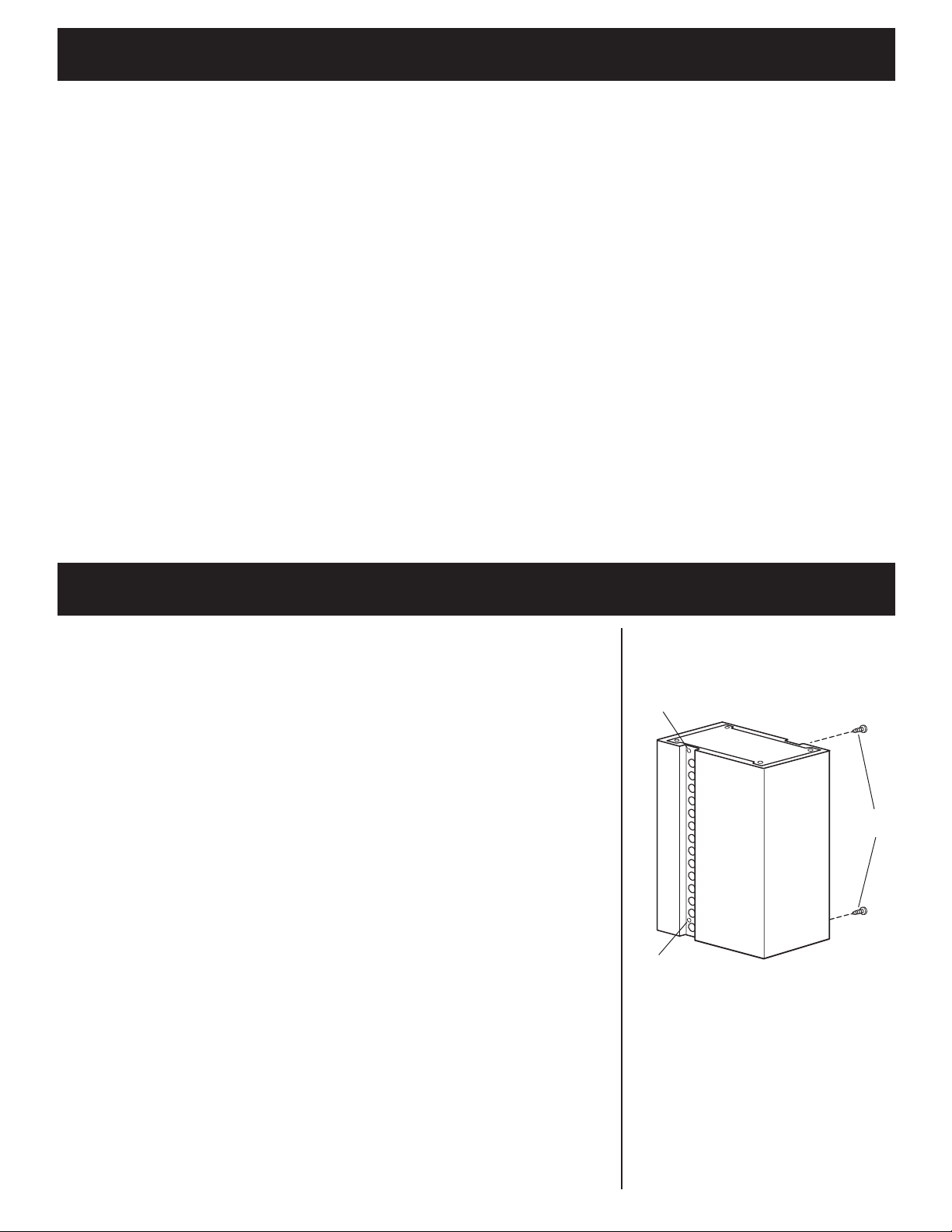
6. Remove the four screws on the
upper chimney and disassemble
chimney pieces from support frame.
slot
1/4" (6.4 mm)
bolt
6
7. Align support mounting bracket
with holes in ceiling. Attach support
system frame to ceiling using anchors
recommended for your type of ceiling:
• Concrete ceiling — use inserts and
screws provided.
• Wood ceiling — use 4" (10.2 cm)
long wood screws.
• Plaster or sheet rock ceiling —
attach support mounting bracket
to ceiling joists if possible. If
ceiling joists are not available, you
must build a supporting structure
behind the plaster or sheet rock.
Make sure the support is connected
firmly to ceiling.
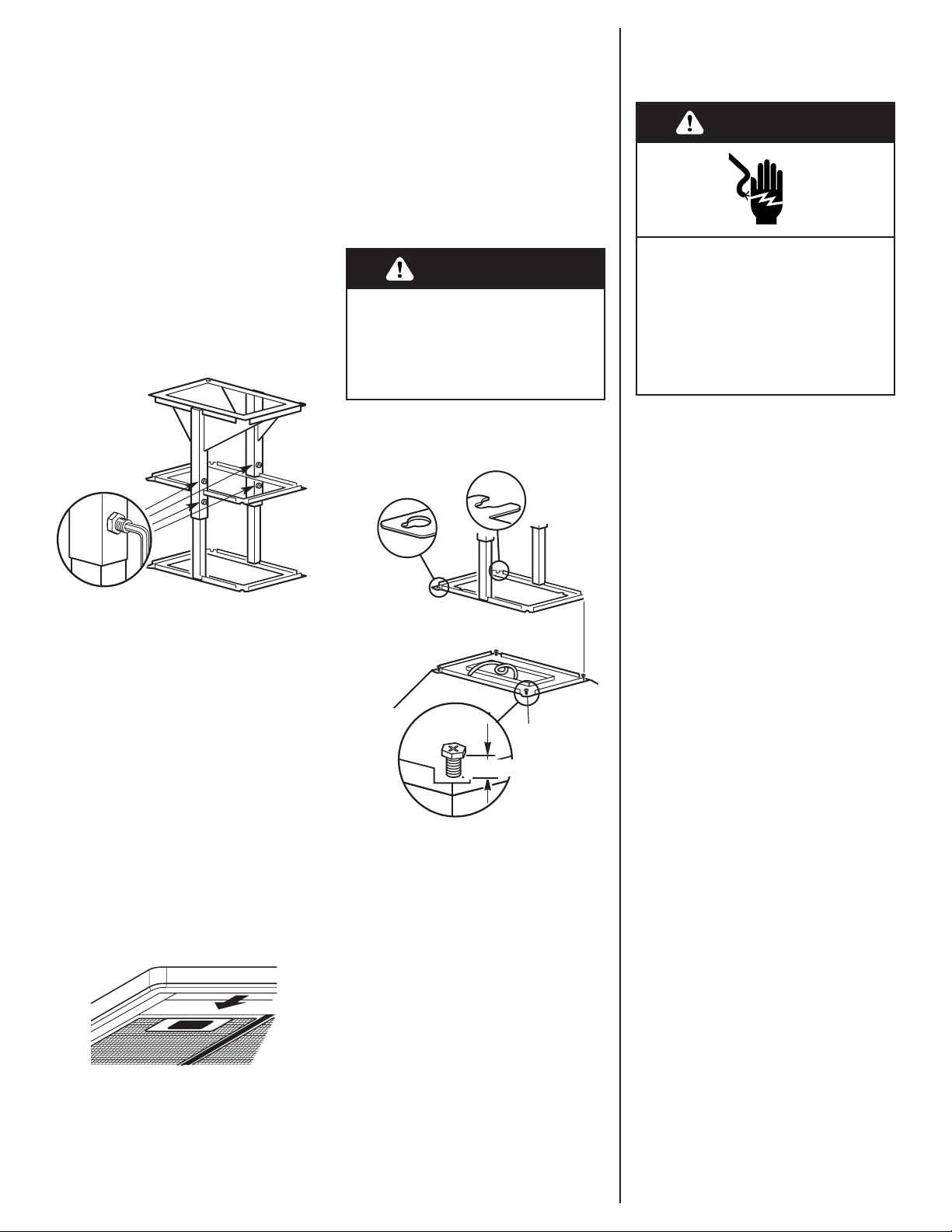
four set
screws
8. Determine the height of the
canopy. The range hood requires at
least 24" (61 cm) of clearance between
bottom of range hood canopy and
cooking surface.
The bottom of the canopy will be
approximately 9" (22.9 cm) below the
bottom of the support system. To
change the canopy height, loosen the
four set screws on the support frame.
Adjust support frame to the desired
length and tighten all four set screws
firmly in place before attaching
canopy.
If used, attach the vent damper to the
inside bottom of the chimney support
frame. Make sure damper opens to
outside.
Excessive Weight Hazard
Use two or more people to move
and install island canopy hood.
Failure to do so can result in back
or other injury.
9. Press on handle in front of
filters to release filters from range
hood canopy. Remove filters and set
aside.
WARNING
.
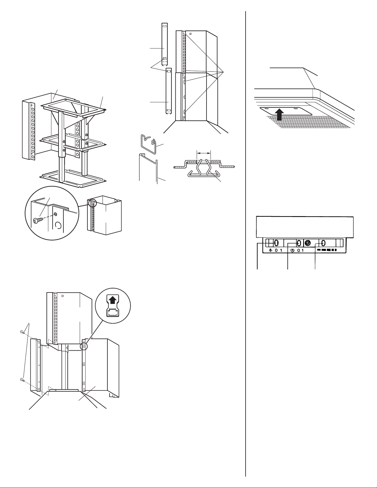
10. Remove the terminal box
cover from the range hood. Remove
the power supply cable knockout
using a flat-blade screwdriver. Do not
remove optional remote blower
knockout. Attach conduit connector
into power supply cable opening so
that conduit connector clamping
screws are inside the terminal box.
11. Loosen four bolts located
next to exhaust opening so that there
is approximately 1/4" (6.4 mm) space
between bolt head and canopy. Lift
canopy and insert bolts into slots in
support system frame. Tighten bolts
to support system frame and canopy.
Electrical
connection
Electrical Shock Hazard
Disconnect power before
making electrical connections.
Connect ground wire to green
ground screw in terminal box.
Failure to do so can result in
death or electrical shock.
WARNING
12 . Make electrical connection:
Disconnect power supply.
Feed enough power supply cable
through conduit connector to
make electrical connections.
Connect the power supply cable to
hood terminal box through the
U.L.- or C.S.A.-listed conduit
connector.
Connect the white wire of the
power supply cable with the white
lead in the hood using a twist-on
connector; connect the black wire
of the power supply cable with the
black lead in the hood using a
twist-on connector.
Connect the power supply green
(green and yellow) ground wire
under the green, ground screw.
Tighten conduit connector screws.
Replace the terminal box cover.
7
Install chimney
sections
Check operation
13 . Connect vent to damper or
hood and seal all connections with
duct tape.
upper
chimney
lower
chimney
upper
chimney
trim
clip
clips
chimney
holes
lower
chimney
trim
15 . Cut upper chimney trim to
correct length. Be careful not to bend
strips while cutting. Slide clips into
trim. Postion to align with chimney
holes. Push trim strips so that clips
snap into holes.
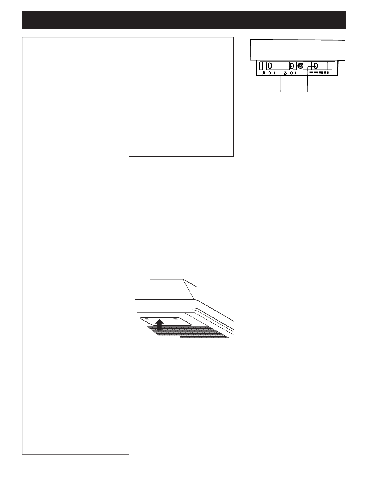
16 . Place filters in canopy
opening so rear edge is over flange.
Press filters up into position.
Fit lower chimney section over upper
chimney section. Note: clip hole
arrows must point toward ceiling.
Check for proper position. Then
secure upper and lower chimney
sections to support system frame with
four screws.
14 . Position upper chimney
section on support system frame and
secure with two screws.
clip
chimney
holes
trim
upper chimney
support
system frame
screw
screws
upper
chimney
control panel
location
light
switch
blower
switch
blower speed
switch
19 . Check the operation of the
range hood:
Move light switch to “1” position.
The light should turn on.
Move blower switch to “1”
position. The blower should
operate.
Move the blower speed switch to
the far left; blower speed should
be LOW. Move blower speed to
right; blower speed should
gradually increase until you reach
HIGH speed at far right.
Move blower and light switches to
“0” position to turn blower and
light off.
If range hood does not operate:
Check that the circuit breaker is
not tripped or the house fuse
blown.
Disconnect power supply. Check
that wiring is correct.
18 . The island canopy hood
controls are located in a grey panel on
underside of the canopy. To open the
panel, press on the front edge of
panel and release. The control panel
will drop down.
17. Turn power on.
8
Use and Care Information
WARNING — TO REDUCE THE
RISK OF FIRE, ELECTRIC SHOCK,
OR INJURY TO PERSONS,
OBSERVE THE FOLLOWING:
Use this unit only in the manner
intended by the manufacturer. If
you have questions, contact the
manufacturer. Before servicing or
cleaning unit, switch power off
at service panel and lock switch
power off at service panel and
lock service panel to prevent
power from being switched on
accidentally. When the service
disconnecting means cannot be
locked, securely fasten a
prominent warning device such
as a tag to the service panel.
CAUTION: For general ventilating
use only. Do not use to exhaust
hazardous or explosive materials
and vapors.
WARNING — TO REDUCE THE
RISK OF A RANGE TOP GREASE
FIRE:
Never leave surface units
unattended at high settings.
Boilovers cause smoking and
greasy spillovers that may ignite.
Heat oils slowly on low or
medium settings.
Always turn hood ON when
cooking at high heat or when
cooking flaming foods.
Clean ventilating fans frequently.
Grease should not be allowed to
accumulate on fan or filter.
Use proper pan size. Always use
cookware appropriate for the size
of the surface element.
WARNING — TO REDUCE THE
RISK OF INJURY TO PERSONS
IN THE EVENT OF A RANGE TOP
GREASE FIRE, OBSERVE THE
FOLLOWING:
SMOTHER FLAMES with a closefitting lid, cookie sheet, or metal
tray, then turn off the burner. BE
CAREFUL TO PREVENT BURNS.
If the flames do not go out
immediately, EVACUATE AND
CALL THE FIRE DEPARTMENT.
NEVER PICK UP A FLAMING PAN
— You may be burned.
DO NOT USE WATER, including
wet dishcloths or towels — a
violent steam explosion will
result. Use an extinguisher
ONLY if:
You know you have a Class ABC
extinguisher, and you already
know how to operate it.
The fire is small and contained in
the area where it is started.
The fire department is being
called.
You can fight the fire with your
back to an exit.
Operating the light:
ON: Move the light switch to the “1”
position.
OFF: Move the light switch to the “0”
position.
Operating the blower:
ON: Move the blower switch to the
“1” position.
OFF: Move the blower switch to the
“0” position.
Adjusting the blower speed:
The blower has variable speed
control.
Move the switch to the far left for
LOW speed and to the far right for
HIGH speed.
Closing the range hood control
panel:
Push up on the front edge of the
control panel. The control panel will
slide up into the canopy.
Operation
The island canopy hood is designed
to remove smoke, cooking vapors and
odors from the cooktop area. For best
results, start the range hood before
cooking and allow it to operate
several minutes after the cooking is
complete to clear all smoke and odors
from the kitchen.
Cleaning
Filters:
The filters should be washed
frequently. Place metal filters in
dishwasher or hot detergent solution
to clean.
Exterior surfaces:
Clean the hood with a mild detergent
and soft cloth. Do Not use abrasive
cleanser or steel wool pads.
Opening the island canopy
hood control panel:
The hood controls are located in a
grey panel on the underside of the
canopy. To open the panel, press on
the front edge of panel and release.
The control panel will drop down.
control panel
location
light
switch
blower
switch
blower speed
switch
This fan suitable for use with solidstate speed controls.
 Loading...