


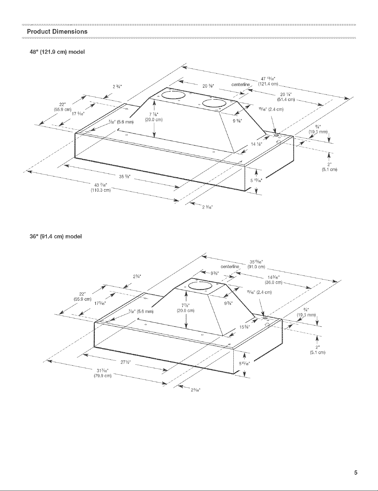
KitchenAid KICU265HBT1, KHVU781RSS1, KHVU781RSS0, KHVU761RSS1 Owner’s Manual

48' (121.9cm)
avec
36' (91,4) et 48" (121,9 cm)
TaMe of Contents/Table des matieres ............................................................................. 2
Model/ModUle
36" (91,4 cm)
IMPORTANT: READ AND SAVE THESE INSTRUCTIONS,
FOR RESIDENTIAL USE ONLY.
IMPORTANT : LIRE ET CONSERVER DES INSTRUCTIONS,
POUR UTILISATION RESIDENTIELLE UNIQUEMENT.
IMPORTANT:
Installer: Leave installation instructions with the homeowner.
Homeowner: Keep installation instructions for future reference.
Save installation instructions for local inspector's use.
IMPORTANT :
lnstallateur : Remettre les instructions d'instailation au proprietaire.
PropriStaRe : Conserver les instructions d'installation pour consultation uit_rieure.
Conserver les instructions d'instatlation pour consultation par I'inspecteur local.
Model/Modete
48" (121,9 cm)
9763388
TABLEOF CONTENTS
TABLEDESMATIF,RES
RANGE HOOD SAFETY ............................... 2
iNSTALLATiON REQUIREMENTS ....................... 4
Tools and Parts ..................................... 4
Location Requirements ............................. 4
Venting Requirements .............................. 6
Electrical Requirements ............................. 7
iNSTALLATiON iNSTRUCTiONS ........................ 7
Prepare Location .................................. 7
Make Electrical Connection .......................... 8
Complete installation ............................... 9
Check Operation .................................. 9
RANGE HOOD USE .................................. 10
Operation ....................................... 10
RANGE HOOD CARE ................................ 10
Cleaning and Maintenance ......................... 10
Accessories ..................................... 10
REQUESTING ASSISTANCE OR SERVICE .............. 1t
RANGE HOOD WARRANTY ........................... 12
WiRiNG DIAGRAM .................................. 13
S_:CURITE DE LA HOTTE DE CUISINI_:RE .............. 14
EXIGENCES D'INSTALLATION ........................ 16
Outillage et pieces .................................. 16
Exigences d'emplacement .......................... 16
Exigences concernant I'evaeuation ................... 18
Specifications ebctriques .......................... 19
INSTRUCTIONS DqNSTALLATION ..................... 20
Preparation de I'emplacement ....................... 20
Raccordement electrique ........................... 20
Achever I'installation .............................. 21
Contr61e du fonctionnement ........................ 21
UTILISATiON DE LA HOTTE DE CUISINIERE ............ 22
Fonctionnement .................................. 22
ENTRETIEN DE LA HOTTE DE CUISINIERE ............. 22
Nettoyage et entretien ............................. 22
Accessoires ..................................... 23
DEMANDE D'ASSlSTANCE OU DE SERVICE ............ 24
GARANTIE DE LA HOTTE DE CUISINIERE .............. 25
SCHEMA DE CABLAGE .............................. 26
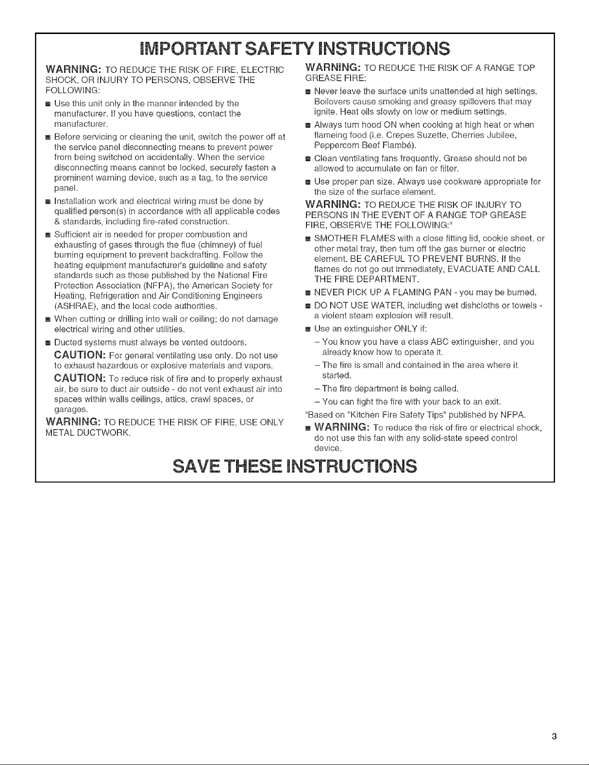
RANGEHOODSAFETY
Your safety and the safety of others are very important.
We have provided many important safety messages in this manual and on your appliance. Always read and obey all safety
messages.
This is the safety alert symbol.
This symbol alerts you to potential hazards that can kill or hurt you and others.
All safety messages will follow the safety alert symbol and either the word "DANGER" or "WARNING."
These words mean:
You can be killed or seriously injured if you don't immediately'
follow instructions.
You can be killed or seriously injured if you don't follow
instructions.
All safety messages will tell you what the potential hazard is, tell you how to reduce the chance of injury, and tell you what can
happen if the instructions are not followed.
iMPORTANT SAFETY iNSTRUCTiONS
WARNmNG: TO REDUCE THE RiSK OF FIRE, ELECTRIC
SHOCK, OR iNJURY TO PERSONS, OBSERVE THE
FOLLOWING:
m Use this unit only in the manner intended by the
manufacturer, if you have questions, contact the
manufacturer.
m Before servicing or cIeaning the unit, switch the power off at
the service panel disconnecting means to prevent power
from being switched on accidentaiIy. When the service
disconnecting means cannot be locked, securely fasten a
prominent warning device, such as a tag, to the service
panel.
m installation work and electrical wiring must be done by
qualified person(s) in accordance with alI applicable codes
& standards, including fire-rated construction.
m Sufficient air is needed for proper combustion and
exhausting of gases through the flue (cMmney) of fuel
burning equipment to prevent backdrafting. Follow the
heating equipment manufacturer's guideline and safety
standards such as those published by the National Fire
Protection Association (NFPA), the American Society for
Heating, Refrigeration and Air Conditioning Engineers
(ASHRAE), and the local code authorities.
m When cutting or drilling into walI or ceiling; do not damage
electrical wiring and other utilities.
m Ducted systems must always be vented outdoors.
CAUTION: For general ventilating use only. Do not use
to exhaust hazardous or explosive materials and vapors.
CAUTmON: To reduce risk of fire and to properly exhaust
air, be sure to duct air outside - do not vent exhaust air into
spaces within walls ceilings, attics, crawl spaces, or
garages.
WARNING: TO REDUCE THE RiSK OF FIRE, USE ONLY
METAL DUCTWORK.
WARNING: TO REDUCE THE RiSK OF A RANGE TOP
GREASE FIRE:
m Never Ieave the surface units unattended at high settings.
Boilovers cause smoking and greasy spiIIovers that may
ignite. Heat oils siowiy on low or medium settings.
m Always turn hood ON when cooking at high heat or when
flameing food (i.e. Crepes Suzette, Cherries Jubilee,
Peppercorn Beef Flamb@.
m Clean ventilating fans frequently. Grease shouId not be
allowed to accumulate on fan or fiIter.
m Use proper pan size. Always use cookware appropriate for
the size of the surface element.
WARNING: TO REDUCE THE RISK OF iNJURY TO
PERSONS iN THE EVENT OF A RANGE TOP GREASE
FIRE, OBSERVE THE FOLLOWING: _
m SMOTHER FLAMES with a close fitting Iid, cookie sheet, or
other metal tray, then turn off the gas burner or electric
element. BE CAREFUL TO PREVENT BURNS. if the
flames do not go out immediately, EVACUATE AND CALL
THE FiRE DEPARTMENT.
m NEVER PiCK UP A FLAMING PAN _you may be burned.
m DO NOT USE WATER, including wet dishcloths or towels -
a vioIent steam explosion will result.
m Use an extinguisher ONLY if:
- You know you have a class ABC extinguisher, and you
already know how to operate it.
- The fire is small and contained in the area where it
started.
- The fire department is being called.
- You can fight the fire with your back to an exit.
aBased on "Kitchen Fire Safety Tips" published by NFPA.
® WARNING: To reduce the risk of fire or electrical shock,
do not use this fan with any solid-state speed control
device.
SAVE THESE iNSTRUCTiONS
INSTALLATIONREQUIREMENTS
Gather the required tools and parts before starting installation.
Read and follow the safety instructions provided with any tools
listed here.
Tools needed:
level
drill with 11/4"and %2" drill bits
pencil
wire stripper or utility knife
measuring tape or ruler
pliers
caulking gun and weatherproof caulking compound
duct tape
jig saw or keyhole saw
flat blade screwdriver
metal snips
Phillips screwdriver
Parts needed:
3/4"(19.0 mm) UL- or CSA-listed strain relief
power supply cable
metal vent system
IMPORTANT: Observe all governing codes and ordinances.
Hood location should be away from strong draft areas, such as
windows, doors and strong heating vents.
Installation clearance dimensions that are shown must be used.
Given dimensions provide minimum clearance.
NOTE: Hood liner must be surrounded by a custom built
enclosure.
Cooktop to hood clearance wilI depend on the material the
builder uses to enclose the liner.
Grounded electrical outlet is required. See "Electrical
requirements" section.
It is recommended that the hood be fastened to solid wood.
The hood is factory set for venting through the roof or wall.
All openings in ceiling and wall where the hood will be installed
must be sealed.
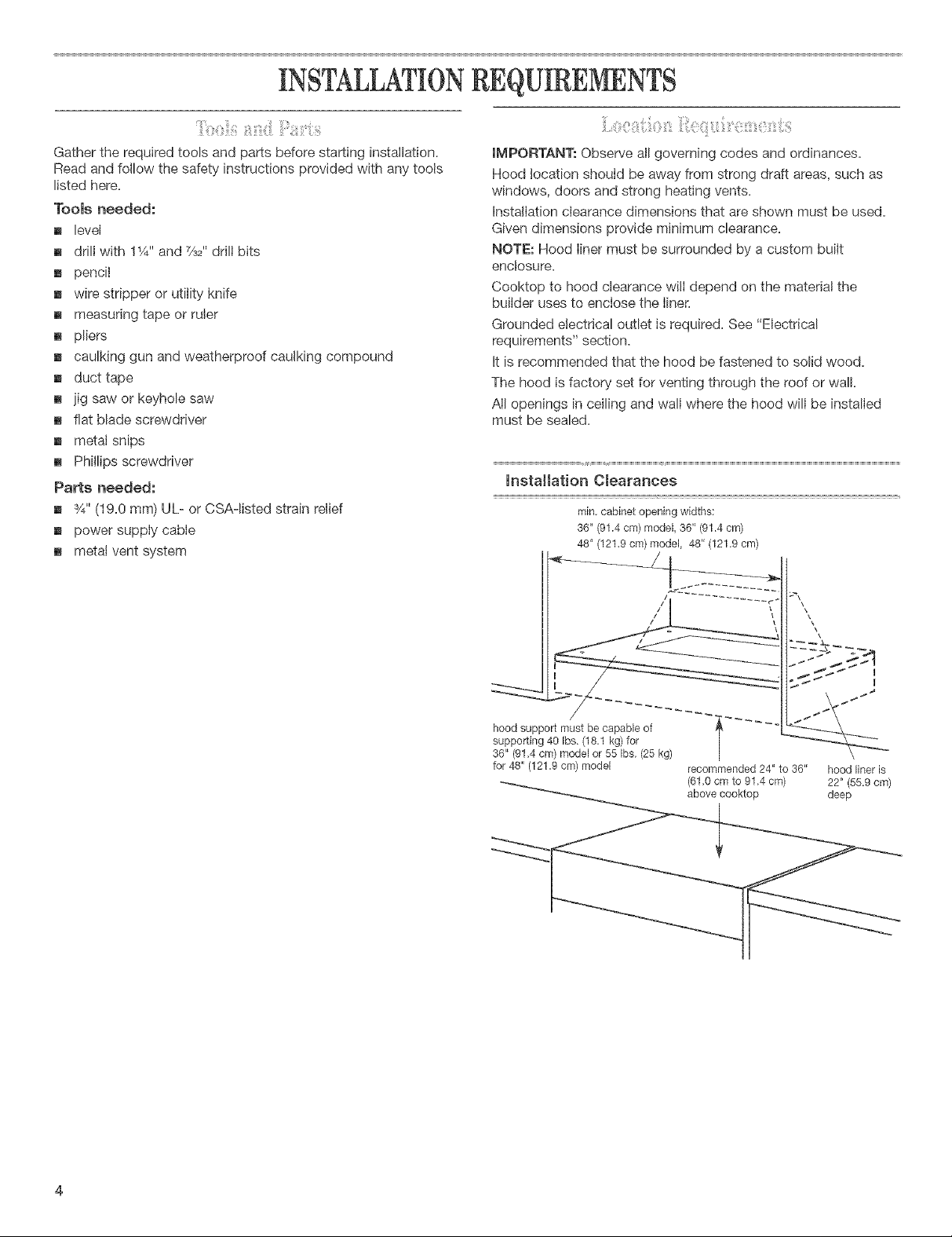
Installation Clearances
min, cabinet opening widths:
36" (91.4 cm) model, 36" (91.4 cm)
48" (121.9 cm) model, 48" (121,9 cm)
hood support must be capable of
supporting 40 Ibs. (18,1 kg) for |
36" (91,4 cm)modelor55Ibs,(25 kg) |
for48"(121,9 cm) model recommended24"to 36"
(61,0 cmto91.4cm)
above cooktop
hood liner is
22' (55.9 cm)
deep
.s
, /
\
[] 36" (91.4 cm) model requires a 6" (15.2 cm) round vent
system. 48" (121.9 cm) model requires two 6" round vent
systems or a 10" (25.4 cm) round system using vent transition
kit number 4396915.
[] Vent system must terminate to the outside.
[] Do not terminate the vent system in an attic or other enclosed
area.
[] Do not use 4" (10.2 cm) laundry-type wall caps.
[] Use metal vent only. Rigid metal vent is recommended. Do
not use plastic or metal foii vent.
For the most efficient and quiet operation:
[] Use a straight run or as few elbows as possible.
[] Use no more than three 90° elbows.
[] Make sure there is a minimum of 24" (61 cm) of straight vent
between the elbows if more than one elbow is used.
[] Do not install two elbows together.
[] Use duct tape to seal all ioints in the vent system.
[] Use caulking to seal exterior wall or roof opening around
the cap.
Cold weather instammations
An additional backdraft damper should be installed to minimize
backward cold air flow and a nonmetallic thermal break to
minimize conduction of outside temperatures as part of the vent
system. The damper should be on the cold air side of the thermal
break.
The break should be as close as possible to where the vent
system enters the heated portion of the house.
Make up air
Local building codes may require the use of make-up air systems
when using ventilation systems greater than specified CFM of air
movement. The specified CFM varies from locale to locale.
Consult your HVAC professional for specific requirements in
your area.
Venting Methods
This canopy hood is factor},, set for venting through the roof
or wail.
The 36" (91.4 cm) model requires a 6" (15.2 cm) round vent
system for installation (not included). The 48" (121.9 cm) model
requires two 6" (15.2 cm) round vent systems or a 10" (25.4 cm)
round vent system for installation. The hood exhaust opening is
6" (15.2 cm) round.
NOTE: Flexible vent is not recommended. Flexible vent creates
back pressure and air turbulence that greatly reduces
performance.
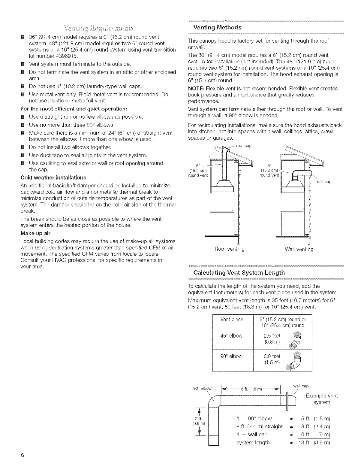
Vent system can terminate either through the roof or wall. To vent
through a wall, a 90° elbow is needed.
For recirculating installations, make sure the hood exhausts back
into kitchen, not into spaces within wall, ceilings, attics, crawl
spaces or garages.
.fJ roof cap
(15,2crn)
round vent
wall cap
Roof venting Wall venting
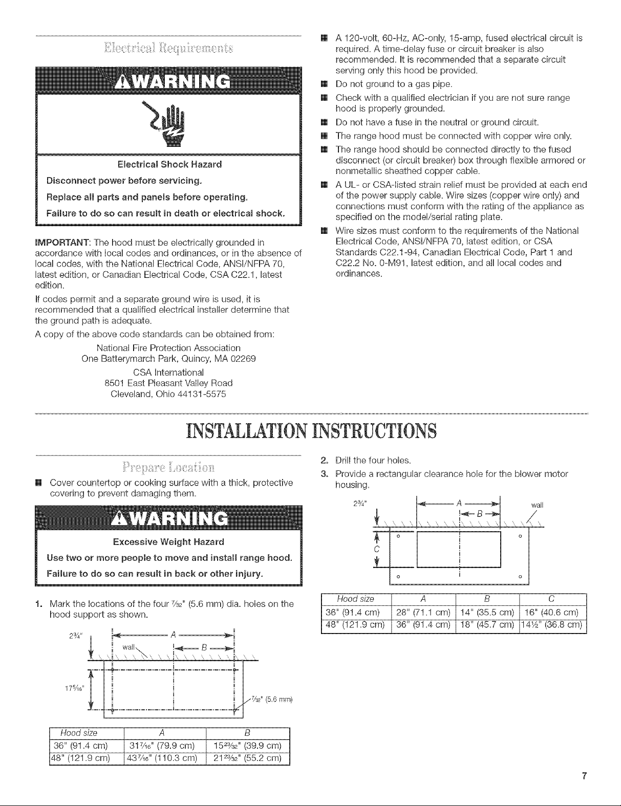
CaJcutating Vent System Length
To calculate the length of the system you need, add the
equivalent feet (meters) for each vent piece used in the system.
Maximum equivalent vent length is 35 feet (10.7 meters) for 6"
(15.2 cm) vent, 60 feet (18.3 m) for 10" (25.4 cm) vent.
Vent piece
6" (152 cm) round or
10" (25.4cm) round
450elbow
2.5 feet
(0.8 m) ............
900elbow 5.0 feet
(1.5 m)
90° elbow _6 ft. (1,8 m)----------_l wall cap
_X'_ _' _ Example vent
2ft, I I 1 -- 90 elbow = 5 ft. (1.5 m)
(06 m)
I I 8 ft. (2.4 m) straight = 8 ft. (2.4 m)
1 -- wail cap = 0 ft. (0 m)
h=J system length = 13 ft. (3.9 m)
ElectricalShockHazard
Disconnectpower before servicing,
Replace all parts and panels before operating,
Failure to do so can result in death or electrical shock.
IMPORTANT: The hood must be electrically grounded in
accordance with Iocal codes and ordinances, or in the absence of
local codes, with the National Electrical Code, ANSI/NFPA 70,
latest edition, or Canadian Electrical Code, CSA C22.1, latest
edition.
If codes permit and a separate ground wire is used, it is
recommended that a qualified electrical installer determine that
the ground path is adequate.
A copy of the above code standards can be obtained from:
National Fire Protection Association
One Batterymarch Park, Quincy, MA 02269
CSA International
8501 East Pleasant Valley Road
Cleveland, Ohio 44131-5575
[] A 120-volt, 60-Hz, AC-only, 15-amp, fused electrical circuit is
required. A time-delay fuse or circuit breaker is also
recommended. It is recommended that a separate circuit
serving only this hood be provided.
[] Do not ground to a gas pipe.
[] Check with a qualified electrician if you are not sure range
hood is properly grounded.
[] Do not have a fuse in the neutral or ground circuit.
[] The range hood must be connected with copper wire only.
[] The range hood should be connected directly to the fused
disconnect (or circuit breaker) box through flexible armored or
nonmetallic sheathed copper cable.
[] A UL- or CSA-Iisted strain relief must be provided at each end
of the power supply cable. Wire sizes (copper wire only) and
connections must conform with the rating of the appliance as
specified on the model/serial rating plate.
[] Wire sizes must conform to the requirements of the National
Electrical Code, ANSI/NFPA 70, latest edition, or CSA
Standards C22.1-94, Canadian Electrical Code, Part 1 and
C22.2 No. 0-M91, latest edition, and all local codes and
ordinances.
INSTALLATIONiNSTRUCTiONS
[]
Cover countertop or cooking surface with a thick, protective
covering to prevent damaging them.
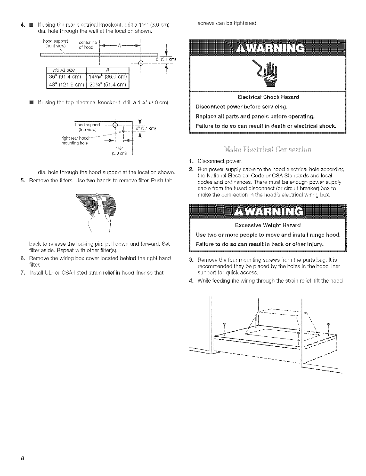
Mark the locations of the four %2" (5.6 mm) dia. holes on the
hood support as shown.
2sA,,
17qe"
I I
2. Drill the four holes.
3. Provide a rectangular clearance hole for the blower motor
housing.
23/4 _
Hood size A B C
36" (91.4 cm) 28" (71.1 cm) 14" (35.5 cm) 16" (40.6 cm)
48" (121.9 cm) 36" (91.4 cm) 18" (45.7 cm) 14_A'' (36.8 cm)
wall
Hood size A B
36" (91.4 cm) 317/_6"(79.9 cm) 152%2'' (39.9 cm)
48" (121.9 cm) 437/_6'' (110.3 cm) 212%#, (55.2 cm)
4,
if using the rear electrical knockout, drill a 11/4"(3.0 cm)
dia. hole through the wall at the location shown.
hood support centerline I
I
ofhood
I
I
I
Hood size A
,
36" (91.4 cm) 14s/!6'' (36.0 cm)
48" (121.9 cm) 201/4'' (51.4 cm)
If using the top electrical knockout, drill a 11/4" (3.0 cm)
hood support-_-======_ !-.
(top view) T -_--_ h 2='=(5"1ore)
rightrear hood.............................i_l
mountinghole _ _-_
1W' I
(3_8cm) I
dia. hole through the hood support at the location shown.
5,
Remove the filters. Use two hands to remove filter. Push tab
2'*(5,1 cm)
screws can be tightened.
Electdcam Shock Hazard
Disconnect power before servicing.
Replace aH parts and panems before operating,
Failure to do so can result in death or electricam shock,
f,
Disconnect power.
2,
Run power supply cable to the hood electrical hole according
the National Electrical Code or CSA Standards and local
codes and ordinances. There must be enough power supply
cable from the fused disconnect (or circuit breaker) box to
make the connection in the hood's electrical wiring box.
back to release the locking pin, pull down and forward. Set
filter aside. Repeat with other filter(s).
6, Remove the wiring box cover located behind the right hand
filter.
7, Install UL- or CSA-listed strain relief in hood liner so that
3, Remove the four mounting screws from the parts bag. It is
recommended they be placed by the holes in the hood liner
support for quick access.
4, While feeding the wiring through the strain relief, lift the hood
\\\
liner into place.
5, insert the screws through the support and thread into the
Electricam Shock Hazard
EmectricaHy ground the Mower,
Connect ground wire to green ground screw in
wiring box,
Failure to do so can result in death or electrica{ shock,
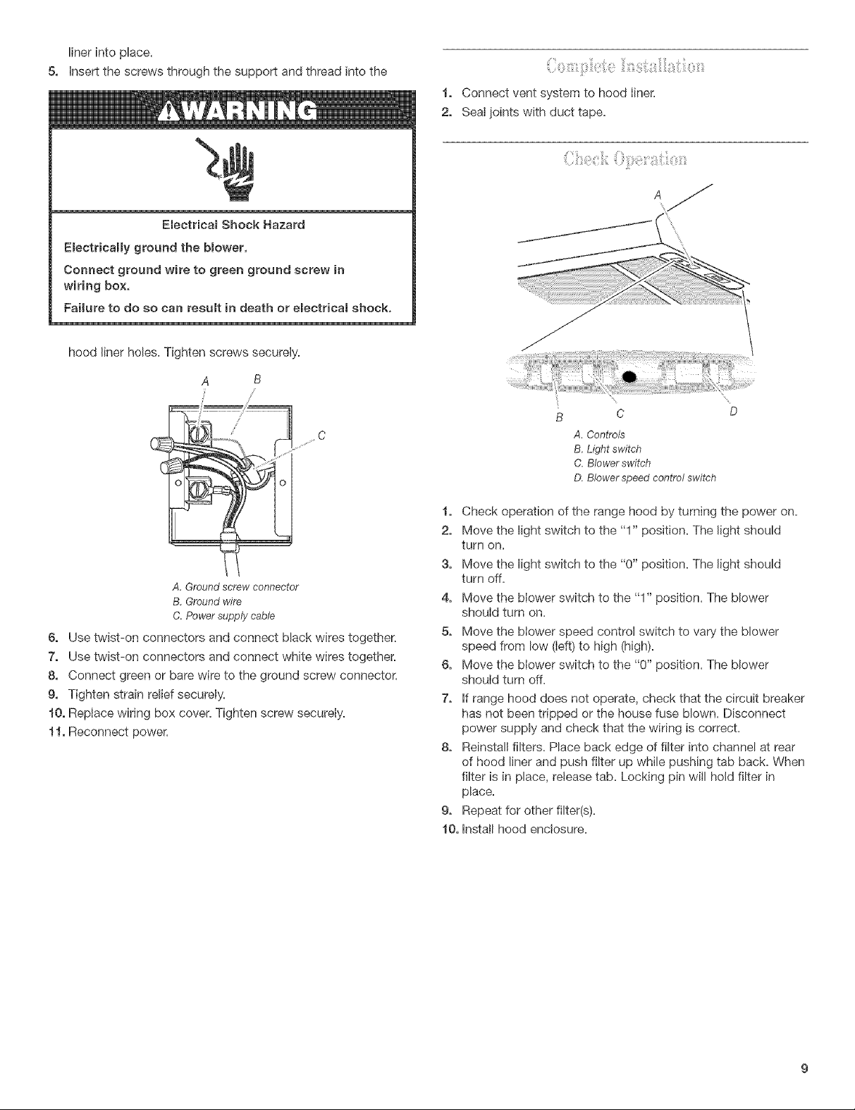
hood liner holes. Tighten screws securely.
A B
Connect vent system to hood liner.
2,
Seal joints with duct tape.
A. Controls
B, Light switch
C. Blower switch
D. BIower speed control switch
C
A,Groundscrewconnector
B,Groundwire
C.Powersupplycable
6, Use twist-on connectors and connect black wires together.
7, Use twist-on connectors and connect white wires together.
8, Connect green or bare wire to the ground screw connector.
9, Tighten strain relief securely.
10, Replace wiring box cover. Tighten screw securely.
11, Reconnect power.
1, Check operation of the range hood by turning the power on.
2, Move the light switch to the "1" position. The light should
turn on.
3, Move the light switch to the "0" position. The light should
turn off.
4, Move the blower switch to the "1" position. The blower
should turn on.
5, Move the blower speed control switch to vary the blower
speed from low (left) to high (high).
6, Move the blower switch to the "0" position. The blower
should turn off.
7, If range hood does not operate, check that the circuit breaker
has not been tripped or the house fuse blown. Disconnect
power supply and check that the wiring is correct.
8, Reinstall filters. Place back edge of filter into channel at rear
of hood liner and push filter up while pushing tab back. When
filter is in place, release tab. Locking pin will hold filter in
place.
9, Repeat for other filter(s).
10, Install hood enclosure.