

KitchenAid KGRT607HWH8, KGRT607HWH9, KGRT607HBT8, KGRT607HBT9, KGRT607HBS9 Installation Guide
...Page 1
®
HOME APPLIANCES 9758571
11 " I "
I C111) e
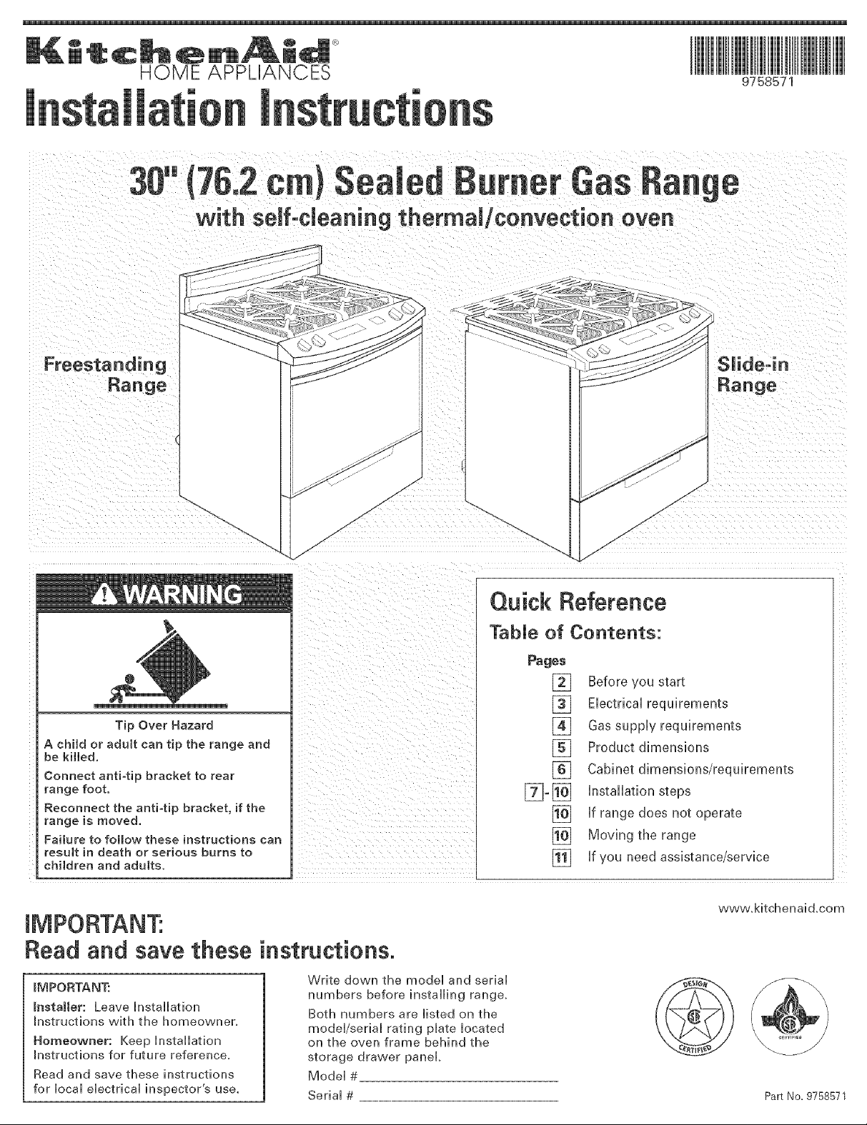
with setf-cJeaning thermal/convection oven
Freestanding Slide=in
Range Range
Quick Reference
TabJe of Contents:
Tip Over Hazard
A child or adult can tip the range and
be killed,
Connect anti=tip bracket to rear
range foot.
Reconnect the anti=tip bracket, if the
range is moved,
Faimure to follow these instructions can
result in death or serious burns to
children and adults. []
Read and save these instructions.
_MPORTANT:
_nstaHer: Leave Installation
Instructions with the homeowner.
Homeowner: Keep Installation
Instructions for future reference,
Read and save these instructions
for local electrical inspector's use.
Write down the model and serial
numbers before installing range,
Both numbers are listed on the
model/serial rating plate located
on the oven frame behind the
storage drawer panel
Model #
Serial # Part No. 9758571
Pages
%-[]
Before ¢ou start
[]
Electrical requirements
[]
[]
Gas supply requirements
Product dimensions
[]
Cabinet dimensions requirements
[]
installation steps
if range does not operate
[]
Moving the range
[]
if you need assistance tservice
www.kitchenaid.com
Page 2
Before you start...
Your safety and the safety of
others are very important.
We have provided many important safety
messages in this manual and on your
appliance. Always read and obey all
safety messages.
This is the safety alert symbol.
This symbol alerts you to
potential hazards that can kill
or hurt you and others.
All safety messages will follow the safety
alert symbol and either the word
'DANGER" or 'WARNING." These
words mean:
You can be killed or seriously injured
if you don't immediately follow
instructions.
You can be kitled or seriously injured
if you don't follow instructions.
All safety messages will tell you what the
potential hazard is, tell you how to
reduce the chance of injury, and tell you
what can happen if the instructions are
not followed.
WARNING: ff the
information in this manua_
is not fommowed exactRy,
a fire or expmosion may
result causing property
damage, persona_ injury
or death.
m Do not store or use
gasoline or other
flammable vapors and
liquids in the vicinity of
this or any other
appliance.
m WHAT TO DO _FYOU
SMELL GAS
o Do not try to right any
appliance.
o Do not touch any
electrical switch.
o Do not use any phone in
your building.
o _mmediatemy caromyour
gas supplier from a
neighbor's phone.
Fo[mow the gas
supp_ier's instructions.
off you cannot reach your
gas supplier, call the fire
department.
_nstam_ation and service
must be performed by a
quamified installer, service
agency or the gas supplier.
IMPORTANT: Observe all governing
codes and ordinances.
Do not obstruct flow of combustion and
ventilation air.
This installation must conform with
all local codes and ordinances. In the
absence of local codes, installation
must conform with American National
Standard, National Fuel Gas Code ANSI
Z223.1 --latest edition x- installation
codes.
It is the customer's responsibility:
• To contact a qualified electrical installer.
• To assure that the electrical installation
is adequate and in conformance with
National Electrical Code, ANSI/NFPA 70
-- latest edition ×-_, and all local codes
and ordinances.
Proper installation is your responsibility.
A qualified technician must install this
range. Make sure you have everything
necessary for correct installation. [t is the
installer's responsibility to comply with
installation clearances specified on the
gas information labekThe gas
information label and model/serial rating
plate are located on the frame behind the
storage drawer.
Check location where range will be
installed.The range should be located for
convenient use in kitchen. Recessed
installations must provide complete
enclosure of the sides and rear of range.
All openings in the wall or floor where
range is to be installed must be sealed.
To eliminate the risk of burns or fire by
reaching over heated surface units,
cabinet storage space located above the
surface units should be avoided. If
cabinet storage is to be provided, the risk
can be reduced by installing a range
hood that proiects horizontally a
minimum of 5 inches beyond the bottom
of the cabinets.
Cabinet opening dimensions that are
shown must be used. Given dimensions
are minimum clearances.
Mobile home installation
The installation of this range must
conform to the Manufactured Home
Construction and Safety Standards, Title
24 CFR, Part 3280 (formerly the Federal
Standard for Mobile Home construction
and Safety, Title 24, HUD, Part 280); or
when such standard is not applicable, the
Standard for Manufactured Homes
Installations (Manufactured Home Sites,
Communities and Setups), ANSI
A225.1/NFPA 501A __, or with local codes.
In Canada, the installation of this range
must conform with the current standards
CAN/CSA-Z240 -- latest edition _, or with
local codes.
When this range is installed in a mobile
home, it must be secured to the floor
during transit. Any method of securing
the range is adequate as long as it
conforms to the standards listed above.
Copies of the standards listed may be obtained
from:
'_CSA International
850! Fast Pleasant Valle',/Rd.
Cleveland, Ohio 44131-5578
_ National Fire Protection Association
One Batterymarch Park
Quincy', Massachusetts, 02269
Page 3

Parts supplied:
Not shown:
• literature pack
• orifice spuds
anti-tip bracket
2 plastic
2 screws
(#10 x 1-I/2")
Bracket must be securely mounted to sub-floor.
Thickness of flooring may require longer screws to
anchor bracket to sub-floor. Longer screws are
available from your local hardware store.
• burner grates and caps
vent cap
• LP conversion orifice spud kit:
1- 0.95 mm cooktop (blue)
2- 0,67 mm cooktop (black)
1- 1.05 mm cooktop (green)
1- #65 broil burner
anchors
Tools needed:
Assemble the required tools and parts
before starting installation. Read and
follow the instructions provided with any
tools listed here.
level
flat-blade screwdriver
Phillips screwdriver
putty knife
pipe wrench
3/8" drive ratchet
3/8" and 5/16" combination wrenches
hand or electric drill
channel lock pliers
measuring tape or ruler
wood floors: 1/8" drill bit
concrete/ceramic floors:
3/16" carbide4ipped masonry drill bit
(Hammer may be needed for anchors.)
Materials needed:
° gas line shutoff valve
• 1/2" male pipe thread nipple for connection
to pressure regulator
• LR gas-resistant pipe-joint compound
• AGA or CSA design-certified flexible metal
appliance connector (4-5 feet) (1.2-1.5 m} or
rigid gas supply line as needed
• Insulated pad or !/4" (6 mm) plywood if
range is installed over carpeting
Electrical requirements
Emectrical Shock Hazard
Plug into a grounded 3 prong outlet.
Do not remove ground prong.
Do not use an adapter.
Do not use an extension cord.
Failure to follow these instructions can
result in death, fire, or electrical shock.
If codes permit and a separate ground
wire is used, it is recommended that a
qualified electrician determine that the
ground path is adequate and that the
outlet is correctly polarized.
Do not ground to a gas pipe.
Check with a qualified electrician if you
are not sure range is properly grounded.
A 120-volt, 60-Hz, AC-only, lO-ampere,
fused electrical supply is required. A
time-delay fuse or circuit breaker is
recommended. It is recommended that a
separate circuit serving only this
appliance be provided.
Electronic ignition systems operate
within wide voltage limits, but proper
grounding and polarity are necessary.
In addition to checking that the outlet is
correctly grounded, the outlet must be
checked by a qualified electrician to see if
it is wired with correct polarity.
IMPORTANT:This range is equipped with
an electronic ignition system that will not
operate if plugged into an outlet that is
not properly polarized.
A wiring diagram is included on the back
of the range.
See "Cabinet dimensions/requirements"
for recommended location of electrical
outlet.
Recommended ground
For personal safety, this range is
equipped with a power supply cord
having a 3 prong ground plug.To
minimize possible shock hazard, the cord
must be plugged into a mating 3 prong,
ground-type outlet, grounded in
accordance with the National Electrical
Code, ANSI/NFPA 70 -- latest edition _, or
CSA Standard C22.1 Canadian Electrical
Code, Part 1 -- latest edition x×-, and aii
local codes and ordinances.
If a mating outlet is not available, it is the
personal responsibility and obligation of
the customer to have a properly
polarized and grounded, 3 prong outlet
installed by a qualified electrician.
3 prong properly polarized
ground-type outlet
3 prong
ground plug
\
power supply
cord
Copies of the standards listed may be obtained
from:
National Fire Protection Association
One Batterymarch Park
Quincy, Massachusetts, 02269
_ CSA International
8501 East Pbasant Valley Rd.
Cleveland, Ohio 44131-5575
Page 4
Gas supply requirements
Explosion Hazard
Use a new AGA or CSA approved gas
supply mine.
mnstall a shutoff vaJve.
Securely tighten all gas connections.
ff connected to LP, have a qualified
person make sure gas pressure does
not exceed 14" (35.6 cm) water column.
Examples of a qualified person
include:
licensed heating personnel,
authorized gas company
personne[_ and
authorized service personnel.
Failure to do so can resumt in death,
explosion, or fire.
In the State of Massachusetts, the
following installation instructions
appiy:
installationsand repairs must be
performed by a qualified or licensed
contractor, plumber, or gasfitter
qualified or licensed by the State
of Massachusetts.
• If using a ball valve, it shall be a
T-handle type,
• A flexible gas connector, when used,
must not exceed 3 feet,
Observe aii governing codes and
ordinances.
This installation must conform with local
codes and ordinances, in the absence of
local codes, installations must conform
with American National Standard,
National Fuel Gas Code ANSi Z223.1 --
latest edition _.
input ratings shown on the model/serial
rating plate are for elevations up to 2,000
feet (610 m). For assistance when
installing the range at higher elevations,
contact your local service compan%
Type of gas: This range is design-
certified by CSA International for use
with Natural gas or, after proper
conversion, for use with LR gas. This
range is factory set for use with Natural
gas. Gas conversion instructions are
provided in "Gas conversions" section.
The model/serial rating plate located on
the frame behind the storage drawer or
broiler door has information on the type
of gas that can be used, If the type of
gas listed does not agree with the type of
gas available, check with the local gas
supplier. Conversion must be done bya
qualified service technician.
Gas supply line: Provide a gas supply
line of 3/4" rigid pipe to the range
location. With LR gas, piping or tubing
size can be 1/2" minimum. A smaller size
pipe on longer runs may result in
insufficient gas supply. Usually, LR gas
suppliers determine the size and
materials used in the system.
Pipe-joint compounds made for use with
LR gas must be used on pipe threads
onl%
Flexible metal appliance connector: If
local codes permit, a new AGA or CSA
design-certified, 1/2" or 3/4" I.D., flexible
metal appliance connector is
recommended for connecting range to
the gas supply line. A 1/2" male pipe
thread nipple is needed for connection to
pressure regulator female pipe threads_
Do not kink or damage the flexible metal
tubing when moving the range.
connection:
Requires a
Rigidpipe
combination of
pipe fittings to
obtain an in-line connection to the range.
All strains must be removed from the
supply and fuel lines so range will be
level and in line.
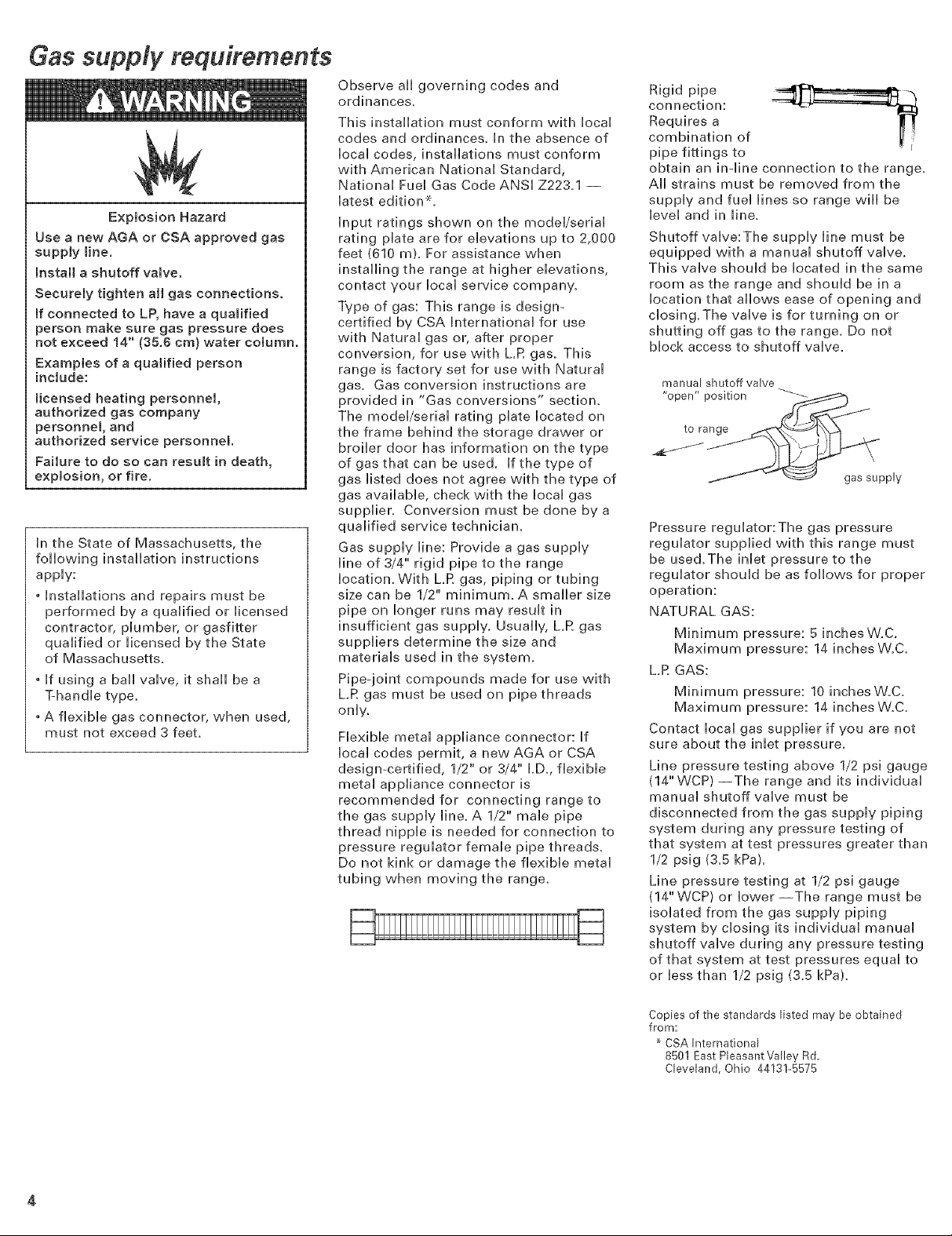
Shutoff valve:The supply line must be
equipped with a manual shutoff valve.
This valve should be located in the same
room as the range and should be in a
location that allows ease of opening and
closing.The valve is for turning on or
shutting off gas to the range. Do not
block access to shutoff valve.
manual shutoff valve
"open" position "-_--
to range
gas supply
Pressure regulator:The gas pressure
regulator supplied with this range must
be used.The inlet pressure to the
regulator should be as follows for proper
operation:
NATURAL GAS:
Minimum pressure: 5 inchesW.C.
Maximum pressure: 14 inches W.C.
LR GAS:
Minimum pressure: 10 inches W.C.
Maximum pressure: 14 inches W.C.
Contact local gas supplier if you are not
sure about the inlet pressure.
Line pressure testing above 1/2 psi gauge
(14" WCP} --The range and its individual
manual shutoff valve must be
disconnected from the gas supply piping
system during any pressure testing of
that system at test pressures greater than
1/2 psig (3.5 kPa).
Line pressure testing at 1/2 psi gauge
(14" WCP} or lower--The range must be
isolated from the gas supply piping
system by closing its individual manual
shutoff valve during any pressure testing
of that system at test pressures equal to
or less than 1/2 psig (3.5 kPa).
Copies of the standards listed may be obtained
from:
CSA International
8501 East Pleasant Valley Rd.
Cbveland, Ohio 44131-5575
Page 5

Product dimensions
Grounded eHectricaH outlet is required. See "EHectricaH requirements['
Proper gas suppH¥ connection must be avaHaMe. See "Gas suppH¥ requirements."
30" (702 cm)jj//_P-
range width
Freestanding Range
8-1/4" (2! cm)
30-1/8"
(91.8 cm)
cooktop
height
44-3/8" (112.7 cm)
SUide4n Range
27-3/4" (70.5 cm)
depth with handle
_MPORTANT: Rear vent must
not be obstructed for proper
ventilation on aH sHideqn
modeHs. See step 6, page 7.
1-1/2" (3.8 cm)
36-1/8" (91.8 cm)
cooktop height
spacer
27-3/4" (70.5 cm)
depth with handle
30" (70.2 cm) width
Page 6

Cabinet dimensions/requirements
Cabk_et opening dimensions shown are for:
25"' (63.5 cm) countertop depth, 24" (61 cm) base
cabinet depth, 36"' (91.4 cm) countertop height
Freestanding or SUide-in Range
4" (10.2 cm) rain. clearance from
both sides of range to side wall
or other combustible material.
Gas line opening
should be located
within this shaded area
Floor gas line
opening if directly
below regulator
3'*17.6
13" (33 cm) max.
upper cabinet depth
e_1_. opening width
30" (76.2 cm)
...... opening width
m
30" (76.2 cm) cabinet
18"
(45.7 cm)
_.I_" For minimum
clearance to
cooktop, see
NOTE*,
(25.4 cm)
18" (45.7 cm)
upper side cabinet
to countertop
Outlet should be
located witNn the
18" x 10"
45.7 x 25.4 cm)
shaded area
IMPORTANT: Some cabinet and building
materials are not designed to withstand
the heat produced by the oven for baking
and self-cleaning. Check with your builder
or cabinet supplier to make sure that the
materials used will not discolor,
delaminate or sustain other damage.
• Do not pinch the power supply cord
between the range and the wall,
• Do not seal the range to the side cabinets.
• Contact a qualified floor covering installer to
check that the floor covering can withstand
at least 200°F (93°C).
• Use an insulated pad or 1/4" (6 mm)
plywood under range if installing range over
carpeting.
IMPORTANT: Rear vent must not be
obstructed for proper ventilation on all
slide-in models. See step 6, page 7.
Anti-tip bracket
The floor-mounted anti-tip bracket
must be installed.To install the
anti-tip bracket supplied, see page 3
and the anti-tip bracket template/
instruction sheet.
NOTE: 24" (61 cm) m[n. when bottom of wood or
metal cabinet is protected by not less than
1/4" (6.4 ram) flame retardant millboard covered
with not less than No. 28 MSG sheet steel, 0.015"
(0.4 ram) stainless steel, 0.024" (0.6 ram)
aluminum or 0.020" (0.5 ram) copper.
30" (76.2 cm) min. clearance between the top of
the cooking platform and the bottom of an
unprotected wood or metal cabinet.
Page 7

Slide@ ranges:
countertop
preparations
The cooktop sides of the slideqn range fit
over the cutout edge of your countertop.
[f you have a square finish (flatt
countertop and the opening width is 30""
(76.2 cm), no countertop preparation is
required.
Formed front-edged countertops:
Must have molded edge shaved fiat
1/2"" (1.3 cm) from each front corner
of opening.
cm)
30-7/8" (78.4 cm)
J
,_ Formed or tiled
countertop trimmed
1/2" (1.3 cm) back at
front corners of
countertop opening.
22-5/8"
(57,5 cm>
Cooktop sides of "f I_
range fit over edges of [
countertop opening. [
New start...
Excessive Weight Hazard
Use two or more people to move and
instal[ range.
Failure to do so can result in back or
other injury.
1[] Remove shipping materials, tape
and protective film from range. Keep
cardboard bottom and shipping base
under range. Remove oven racks and
parts package from inside oven.
NOTE: [f you are installing a slide-in
range, remove back vent package from
range top. See step 6 for vent installation.
m Take four
ca rd boa rd ---__
corners from the
carton. Stack one
cardboard corner
on top of another. Repeat with other two
corners. Place them lengthwise on the
floor behind the range--to support the
range when it is laid on its back, Firmly
grasp the range and gently lay it on its
back on the cardboard corners.
z Puii cardboard shipping base
firmly to remove.
M Use an adjustable wrench to
loosen the leveling legs 1-1/2 turns.
7_ Check that the type of gas supply is
correct for this range. (See model/serial
rating plate.) If connecting to LR gas,
follow directions in Conversion Kit
included in your literature package.
If connecting to Natural gas, continue
with anti4ip bracket installation.
Anti-tip bracket installation
Tip Over Hazard
A child or adult can tip the range and
be killed.
Connect anti-tip bracket to rear
range foot.
Reconnect the anti-tip bracket, if the
range is moved.
Failure to follow these instructions can
result in death or serious burns to
chi[dren and adults.
Contact a qualified floor covering
installer for the best procedure for
drilling mounting holes through your
type floor covering.
Tile countertops may need trim cut back
1/2"" (1.3 cm) from each front corner
and/or rounded edge flattened.
[f countertop opening width is greater
than 30"" (76.2 cm), adjust the 1/2""
(1.3 cm) dimension.
Countertop must be level. Place level on
countertop, first side to side; then front
to back. if countertop is not level, range
will not be level. Oven must be level for
satisfactory baking conditions.
M Piace cardboard or hardboard in
front of range. Stand range back up onto
cardboard or hardboar&
Rear vent installation (slideqn
ranges only): Remove the outside screws
from rear trim on range. Use screws to
attach rear vent to range.
Rear vent must
be installed,
be necessary to anchor the bracket to the
sub-floor. Longer screws are available
from your local hardware store.
Page 8

Operating position
E Move range chose to cabinet
opening.
[] Remove cardboard or
hardboard from under range, Carefully
move range into final position.
[] Pull drawer open to first stop
position. Lift front of drawer to clear
white wheels in drawer guides, Remove
drawer and set it aside on a protected
surface.
[] Make sure the antFtip bracket
is installed:
Look for the anti-tip bracket securely
attached to fioor.
Slide range back so rear range foot
is under anti-tip bracket,
anti-tip
bracket
range foot
[] if installing the range in a
mobile home, you must secure the range
to the floor. Any method of securing the
range is adequate as long as it conforms
to the standards in the "Mobile home
installation" instructions.
[] Place rack in oven. Place level
on rack, first side to side; then front to
back,
If range is not level, pull range forward
until rear leveling leg is removed from
the anti-tip bracket. Use 3/8" drive ratchet
and channel lock pliers to adjust leveling
legs up or down until range is level, Push
range back into position, Check that rear
leveling leg is engaged in antFtip
bracket.
NOTE: Oven must be level for
satisfactory baking conditions,
Gas and electrical connections
-a_ pressure regulator
)i j and valve assembly
"oj _ flexible manual
d"connector
f j connector shutoff valve
g0° elbow \\
1/Z' flare union adapters
[] Assemble the flexible
connector from the gas supply pipe to
the pressure regulator, located in the
lower left side of the storage drawer
area, in this order: shutoff valve, 1/2"
flare union adapter, flexible connector,
1/2" flare union adapter. Seal aii
openings in floor or wail wherever range
is installed.
1
appropriate for use with L,R gas to seal
all gas connections, If flexible connectors
are used, be certain connectors are not
kinked,
gas supply line, Wait a few minutes for
the gas to move through the gas line.
shall be conducted according to the
following instructions:
Test aii connections by brushing on an
approved non-corrosive leak-detection
solution. Bubbles will show a leak,
Correct any leak found.
[] Use pipe-joint compounds
[] Open the shutoff valve in the
[] Test for gas leaks. Leak testing
[] Plug into a grounded 3 prong
outlet. "8888" should appear in clock
display.
Remove vent cap, cooktop
burner caps and grates from parts
package. Align notches in burner caps
with pins in burner base. Burner caps
should be level when properly
positioned. Place burner grates over
burners and caps. Place vent cap over
vent dome.
_ser grate
vent cap
j_J vent dome
Page 9

Check operation
EJeetronie ignition system
Cooktop and oven burners use electronic
ignitors in place of standing pilots. When
a cooktop control knob is turned to the
"LITE" position, the system creates a
spark to light the burner.This sparking
continues until the control knob is turned
to the desired setting.
When the oven control is turned to the
desired setting, a glow bar heats up
bright orange and ignites the gas. No
sparking occurs and the glow bar
remains on while the burners operate.
Cheek operation of eooktop
burners
[] Push in and OFF
turn each control knob "
The flame should light
to the "LITE" position. _ t__,_
within 4 seconds.The
first time a burner is
lighted it maytake _ °*_. j
longer than 4seconds _° '',*'_o
to light because of air _b MeO
in gas line. Lo
[] If burners do not light
properly, turn cooktop control knob to
the "OFF" position. Check that the power
supply cord is plugged in and the circuit
breaker or fuse has not blown. Check that
the gas shutoff valves are set to the
"open" position, Repeat Step 21. ff a
burner does not light at this point,
contact your KitchenAid dealer or
authorized service company for
assistance.
[] Adjust the height of top burner
flames (some models}. Push in and turn
each cooktop control knob from "LJTE"
to "LO" setting quickly.
The cooktop "LO" burner
flame should be a steady blue
flame approximately 1/4"
(0.64 cm} high. It can be
adjusted using the
adjustment screw in the
center of the valve stem.The
valve stern is located directly
underneath the control knob.
if the "LO" flame needs to be adjusted:
a. Remove the control knob.
__J
adiustment screw _ ,__//
b. Hold the knob stem with a pair of
pliers. Use a small flat-blade
screwdriver to turn the screw
located in the center of the control
knob stem until the flame is the
proper size.
c. Replace the control knob.
d.Test the flame by turning the
control from "LO" to "Hi '/checking
the flame at each setting.
low flame
high flame
Top burner flame appearance
Cheek operation of oven
burner
Open oven door.
Remove the oven rack Remove the oven
bottom and place it on a protected
surface.
[] Push the "BAKE" pad and
"350°F '' will appear in the temperature
displa% Press the "START" pad. "LO" will
appear in the display; then "170°E" The
oven burner should light in 50 to 60
seconds.This delay is normaLThe oven
safety valve requires a certain time
before it will open and allow gas to flow.
Electric ignitors are used to light the
oven and broil burners.
Do not insert any object into the opening
of the protective shield that surrounds
the igniton
Do not dean the area_
@
oven rear
oven burner \ ignitor
Check the oven
burner for proper flame.This
flame should have a 1/2"
(1.3 cm) long inner cone of
bluish-green, with an outer
mantle of dark blue, and
should be clean and soft in
character, No yellow tips, blowing or
lifting of flame should occun
[] If the oven flame needsto be
adjusted, locate the air shutter near the
center rear of range. Loosen the locking
screw and rotate the air shutter until the
proper flame appears.Tighten locking
screw.
oven burner air shutter-
air shutter rotate to
location adiust for
locking "" brass orifice
screw hood (nut)
Push "CANCEL/OFF" pad.
Insert oven bottom tabs into slots in oven
burner area. Check that tabs are correctly
placed in slots. If the oven bottom is not
positioned properly, poor baking
performance could occur. Replace oven
racks.
ser flame
oven burner
Page 10

Check operation ef even broil
burner
R Close the oven door. Press the
"BROIL' pad. "500°F '' wiii appear in the
temperature display. Press the "START"
pad.The oven broil burner should light in
50 to 60 seconds, This delay is normal.
The oven safety valve requires a certain
time before it will open and allow gas to
flow.The first time broil burner is lighted,
it may take longer to light because of air
in gas line.The first few times burner is
used sparks may appear.This is normal.
NOTE: Oven door must be shut for broil
burner to operate.
Look through oven window to
check broil burner for proper flame.The
flame should have a uniform, light blue
appearance around the burner surface.
No yellow tips, blowing or lifting of the
flame shouH occur,
NOTE: The first few times the broil
burner is used, yellow sparks may
appear in the flame.This is normal and
will stop after burner has been used a
few times.
[] Press the "CANCEL/OFF" pad, If
the broil burner flame needs adjustment,
contact your KitchenAid dealer or
authorized service company for
assistance.
[] insert storage drawer into slide
rails on sides of drawer opening. Lift
front of drawer slightly and push firmly
to close drawer,
L.R gas conversion
No attempt shall be made to convert the
range from the gas specified on the
model/serial rating plate for use with a
different gas without consulting the
servicing gas supplier. An LR Gas
Conversion Kit is included in your
literature package.
YOu have just finished instaJiing
your new range.To get the
most efficient use from your
range, read your Use & Care
Guide. Keep JnstaJJation
instructions and Guide dose to
range for easy reference. The
instructions wiJJ make instaJJing
the range in another home as
easy as the first instatJation.
Ifrange does not
operate:
[_ Check that the circuit breaker is not
tripped or the house fuse Nown,
[_ Check that the power supply cord is
plugged into the outlet.
[_ Check that gas line is turned on,
[_ See Use and Care Guide for
troubleshooting list,
10
Moving the range
Tip Over Hazard
A child or adult can tip the range and
be killed.
Connect anti-tip bracket to rear
range foot.
Reconnect the anti-tip bracket, if the
range is moved.
Failure to follow these instructions can
result in death or serious burns to
children and adults.
When moving range, slide range onto
cardboard or hardboard to prevent
damaging the floor covering.
If removing the range is necessary for
cleaning or maintenance:
1. Remove the storage drawer.
2_ Shut off gas supply to the range.
3_ Disconnect gas,
4_ Unplug range or disconnect power.
5_ Slide range forward to complete
cleaning or maintenance.
6_ Make sure the anti-tip bracket is
installed:
• Look for the anti-tip bracket securely
attached to floor.
• Slide range back so rear range foot
is under anti-tip bracket.
anti-tip
J'J bracket
range foot
7. Check that range is level.
8_ Reconnect gas line to range and
check for leaks.
9. Plug in range or reconnect power.
10. Reinstall storage drawer.
Page 11

Requesting assistance or service
To avoid unnecessary service caiis, piease check the "Check Operation" section, it may
save you the cost of a service call. if you still need help, follow the instructions below.
Jf Vou need assistance
or service in U.S.A.
Caff the KitchenAid Customer
_nteraation Center toll-free at
1-800-235-0665.
Our consuitants are avaiiabie to assist
you. When caiiing, piease know the
purchase date, and the compiete
modei and seriai number of your
appliance.This information will help
us better respond to your request.
Our consuitants provide assistance
with:
• Features and specifications on
our full line of appiiances
• Instaiiation information
• Use and maintenance procedures
• Accessory and repair parts saies
• Specialized customer assistance
(Spanish speaking, hearing
impaired, iimited vision, etc.)
•Referrais to iocai deaiers, service
companies, and repair parts
distributors
KitchenAid designated service
technicians are trained to fuifiii the
product warranty and provide after-
warranty service, anywhere in the
United States.
To Hecate the designated KitchenAid
service company in your area, you can
aiso Hook in your telephone directory
Yellow Pages.
For further assistance
if you need further assistance, you can
write to KitchenAid with any questions
or concerns at:
KitchenAid Brand Home
Appiiances
Customer interaction Center
c/o Correspondence Dept.
2000 North M-63
Benton Harbor, MI 49022-2692
Piease inciude a daytime phone
number in your correspondence.
Jf Vou need assistance
or service in Canada
When asking for assistance or service,
piease provide a detaiied description of
the probiem, your appiiance's compiete
modei and seriai numbers, and the
purchase date.This information wiii
heip us respond properiy to your
request,
tf the probJem is not due to one of the
items Jisted in "Check Operation":
Contact the deaier from whom you
purchased your appiiance, or caii the
KitchenAid Canada Customer
interaction Center toii-free, 8:30 a.m. -
6:00 p.m. (EST) at 1-800-235-0665.
tf you need service:
Contact your nearest KitchenAid Canada
Appiiance Service branch or authorized
servicing outiet to service your
appiiance. (See list bellow.)
Make sure the service company you
contact is authorized to service your
appiiance during the warranty period.
For further assistance
if you need further assistance, you can
write to KitchenAid Canada with any
questions or concerns at:
Consumer Reiations Department
KitchenAid Canada
1901 Minnesota Court
Mississauga, Ontario L5N 3A7
Piease inciude a daytime phone number
in your correspondence.
KitchenAid Canada AppUiance Service - Consumer Services
Direct service branches:
BRITISH COLUMBIA 1-800-665-6788
ALBERTA 1-800-661-6291
ONTARIO Ottawa area 1-800-267-3456
(except 807 area code) Outside the Ottawa area 1-800-807-6777
MANITOBA, SASKATCHEWAN
and 807 area code in ONTARIO 1-800-665-1683
QUEBEC Montreal (except South Shore) 1-800-361-3032
South Shore Montreal 1-800-361-0950
Quebec City 1-800-463-1523
Sherbrooke 1-800-567-6966
ATLANTIC PROVINCES 1-800-565-1598
11
Page 12

Part No. 9758571
© 2004 KitchenAid
® RegisteredTrademar!< of IqtchenAid.
i :che
HOME APPLIANCES
Prepared by KitchenAid, Benton Harbor, Michigan 49022
Printed in U.S.A.
02/2004
 Loading...