

Page 1
INSTALLATION INSTRUCTIONS
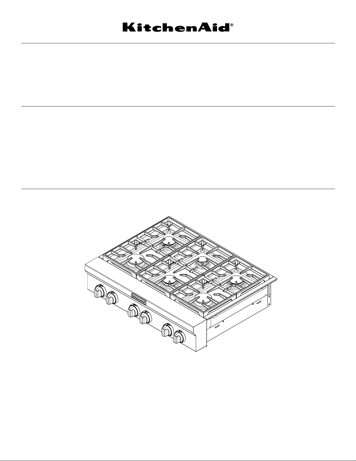
30" (76.2 CM), 36" (91.4 CM) AND 48" (121.9 CM)
COMMERCIAL STYLE GAS COOKTOP S
for residential use only
INSTRUCTIONS D’INSTALLATION -
TABLE DE CUISSON À GAZ DE 30" (76,2 CM),
36" (91,4 CM) ET 48" (121,9 CM) -
MODÈLE COMMERCIAL
pour utilisation résidentielle uniquement
Table of Contents/Table des matières.............................................................................2
IMPORTANT:
Installer: Leave installation instructions with the homeowner.
Homeowner: Keep installation instructions for future reference.
IMPORTANT :
Installateur : Remettre les instructions d'installation au propriétaire.
Propriétaire : Conserver les instructions d'installation pour référence ultérieure.
W10191877A
Page 2

TABLE OF CONTENTS
TABLE DES MATIÈRES
COOKTOP SAFETY........................................................................3
INSTALLATION REQUIREMENTS................................................4
Tools and Parts ............................................................................4
Location Requirements................................................................4
Electrical Requirements ...............................................................7
Gas Supply Requirements...........................................................7
INSTALLATION INSTRUCTIONS..................................................9
Install Cooktop .............................................................................9
Install Optional Backguard...........................................................9
Make Gas Connection .................................................................9
Install Grill Grease Trays ............................................................11
Install Griddle .............................................................................12
Complete Installation .................................................................12
GAS CONVERSIONS....................................................................14
LP Gas Conversion ....................................................................14
Natural Gas Conversion.............................................................16
WIRING DIAGRAMS.....................................................................18
SÉCURITÉ DE LA TABLE DE CUISSON ....................................19
EXIGENCES D’INSTALLATION...................................................20
Outillage et pièces......................................................................20
Exigences d'emplacement.........................................................21
Spécifications électriques ..........................................................24
Spécifications de l'alimentation en gaz .....................................24
INSTRUCTIONS D’INSTALLATION.............................................26
Installation de la table de cuisson..............................................26
Installation du dosseret facultatif...............................................26
Raccordement au gaz................................................................26
Installation des plateaux à graisse du gril..................................28
Installation de la plaque à frire ...................................................29
Achever l'installation ..................................................................29
CONVERSIONS POUR CHANGEMENT DE GAZ.......................31
Conversion pour l'alimentation au propane...............................31
Conversion pour l'alimentation au gaz naturel ..........................33
SCHÉMAS DE CÂBLAGE ............................................................36
2
Page 3
COOKTOP SAFETY
Your safety and the safety of others are very important.
We have provided many important safety messages in this manual and on your appliance. Always read and obey all safety
messages.
This is the safety alert symbol.
This symbol alerts you to potential hazards that can kill or hurt you and others.
All safety messages will follow the safety alert symbol and either the word “DANGER” or “WARNING.”
These words mean:
You can be killed or seriously injured if you don't immediately
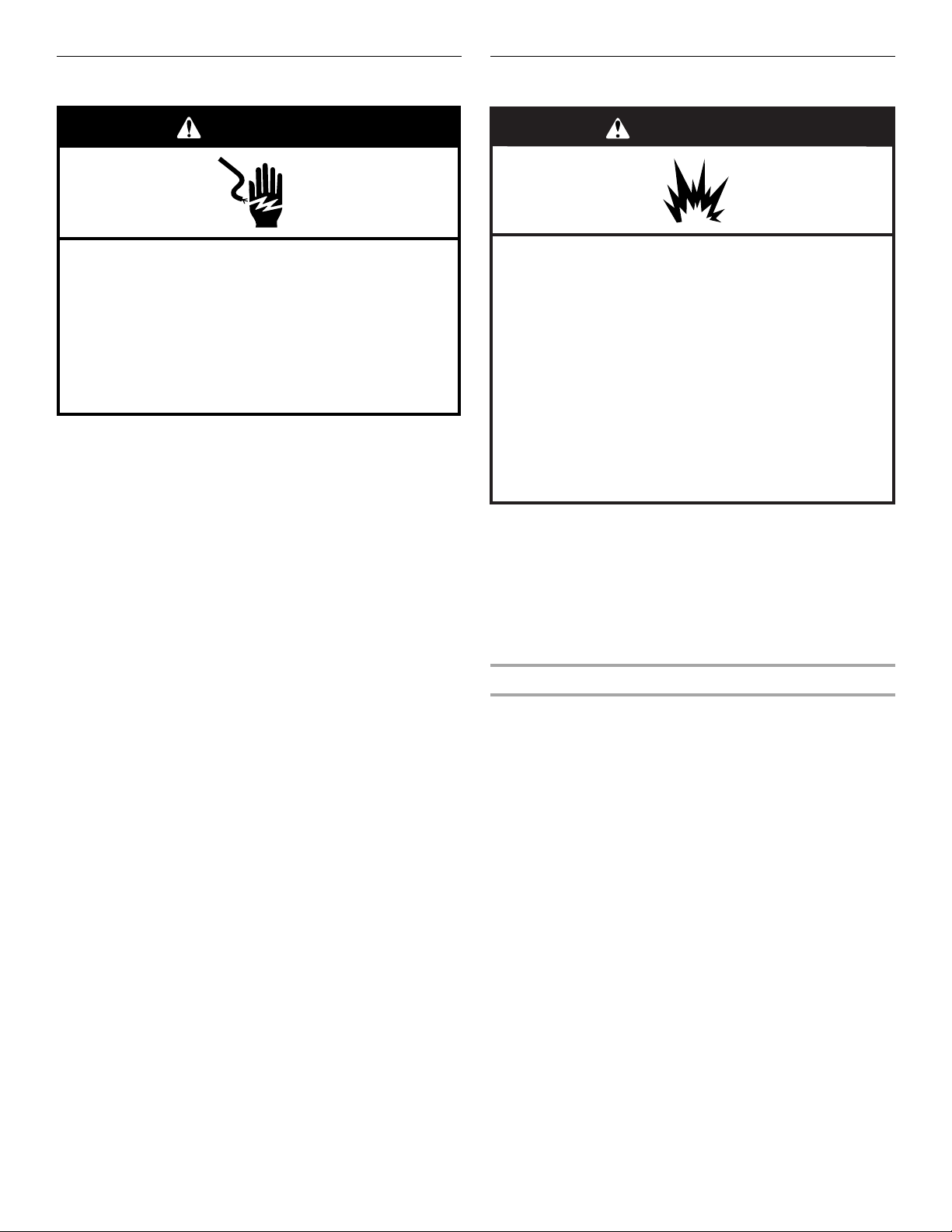
DANGER
WARNING
All safety messages will tell you what the potential hazard is, tell you how to reduce the chance of injury, and tell you what can
happen if the instructions are not followed.
WARNING: If the information in this manual is not followed exactly, a fire or explosion
may result causing property damage, personal injury or death.
follow instructions.
can be killed or seriously injured if you don't
You
instructions.
follow
– Do not store or use gasoline or other flammable vapors and liquids in the vicinity of this
or any other appliance.
– WHAT TO DO IF YOU SMELL GAS:
Do not try to light any appliance.
•
Do not touch any electrical switch.
•
Do not use any phone in your building.
•
Immediately call your gas supplier from a neighbor's phone. Follow the gas supplier's
•
instructions.
If you cannot reach your gas supplier, call the fire department.
•
– Installation and service must be performed by a qualified installer, service agency or
the gas supplier.
WARNING: Gas leaks cannot always be detected by smell.
Gas suppliers recommend that you use a gas detector approved by UL or CSA.
For more information, contact your gas supplier.
If a gas leak is detected, follow the “What to do if you smell gas” instructions.
In the State of Massachusetts, the following installation instructions apply:
■ Installations and repairs must be performed by a qualified or licensed contractor, plumber, or gasfitter qualified or licensed by
the State of Massachusetts.
■ If using a ball valve, it shall be a T-handle type.
■ A flexible gas connector, when used, must not exceed 3 feet.
3
Page 4

INSTALLATION REQUIREMENTS
Tools and Parts
Gather the required tools and parts before starting installation.
Read and follow the instructions provided with any tools listed
here.
Tools Needed
■ Adjustable wrench
■ Tape measure
■ Marker or pencil
■ Pipe wrench
■ Flat-blade screwdriver
■ ¹⁵⁄₁₆" combination wrench
■ Wrench or pliers
■ Pipe-joint compound
resistant to LP gas
■ Noncorrosive leak-
detection solution
Parts Supplied
Check that all parts are included.
■ Gas pressure regulator
■ Burner grates
■ Burner caps
■ Grill grate (on grill models)
■ Wave tray (on grill models)
■ Flame spreader (on grill models)
■ Burner assembly (on grill models)
■ Grease trays (2) (on grill models)
■ Griddle drip tray (on griddle models)
■ Grill drip tray (on grill models)
■ Foam tape
■ LP orifice package (W10221288)
■ Conversion label (8302139)
NOTE: The cooktop is manufactured for use with Natural gas. To
convert to LP gas, see the “Gas Conversions” section.
Parts Needed
36" (91.4 cm) and 48" (121.9 cm) models may require a
backguard. See “Cabinet Dimensions” in the “Location
Requirements” section.
■ 36" (91.4 cm) Retractable Backguard
Order Part Number 8284756
■ 48" (121.9 cm) Retractable Backguard
Order Part Number 8284755
■ 9" (22.9 cm) Backguard for 36" (91.4 cm) Cooktops
Order Part Number W10115776
■ 9" (22.9 cm) Backguard for 48" (121.9 cm) Cooktops
Order Part Number W10115777
■ 22" (55.9 cm) Backguard with Shelf for 36" (91.4 cm)
Cooktops - Order Part Number W10225949
■ 22" (55.9 cm) Backguard with Shelf for 48" (121.9 cm)
Cooktops - Order Part Number W10225948
†®TORX is a registered trademark of Acument Intellectual Properties, LLC.
For LP/Natural Gas
Conversions
■ T15 Torx
■ Adjustable wrench
■ ³⁄₈" drive ratchet
■ ⁷⁄₈" socket
■ ½" deep-well socket
■ 7 mm nut driver
■ Masking tape
®†
screwdriver
To order, see the “Assistance or Service” section of the Use and
Care Guide.
Check local codes and consult gas supplier. Check existing gas
supply and electrical supply. See “Electrical Requirements” and
“Gas Supply Requirements” sections.
High Altitude Conversion
To convert the cooktop for elevations above 6,560 ft (1999.5 m),
order a High Altitude Conversion Kit.
■ Part Number W10237848 - LP high altitude
■ Part Number W10160841 - Natural gas high altitude
To order, see the “Assistance or Service” section of the Use and
Care Guide.
Location Requirements
IMPORTANT: Observe all governing codes and ordinances. Do
not obstruct flow of combustion and ventilation air.
■ It is the installer’s responsibility to comply with installation
clearances specified on the model/serial rating plate. The
model/serial rating plate is located on the underside of the
cooktop burner base.
■ It is recommended that a 600 CFM or larger vent hood be
installed above the cooktop.
■ It is not recommended that a microwave hood combination
be mounted above the cooktop.
■ The cooktop should be installed in a location away from
strong draft areas, such as windows, doors and strong
heating vents or fans.
■ All openings in the wall or floor where cooktop is to be
installed must be sealed.
■ Cabinet opening dimensions that are shown must be used.
Given dimensions are minimum clearances.
■ Grounded electrical supply is required. See “Electrical
Requirements” section.
■ Proper gas supply connection must be available. See “Gas
Supply Requirements” section.
■ The cooktop is designed to hang from the countertop by its
side or rear flanges.
■ The gas and electric supply should be located as shown in
“Gas and Electric Connection Locations” section so that they
are accessible without requiring removal of the cooktop.
■ Provide cutout in left rear corner of cutout enclosure as
shown to provide clearance for gas inlet, power supply cord,
and to allow the rating label to be visible.
IMPORTANT: To avoid damage to your cabinets, check with your
builder or cabinet supplier to make sure that the materials used
will not discolor, delaminate or sustain other damage.
Mobile Home - Additional Installation Requirements
The installation of this cooktop must conform to the
Manufactured Home Construction and Safety Standard, Title 24
CFR, Part 3280 (formerly the Federal Standard for Mobile Home
Construction and Safety, Title 24, HUD Part 280). When such
standard is not applicable, use the Standard for Manufactured
Home Installations, ANSI A225.1/NFPA 501A or local codes.
In Canada, the installation of this cooktop must conform with the
current standards CAN/CSA-A240-latest edition, or with local
codes.
4
Page 5
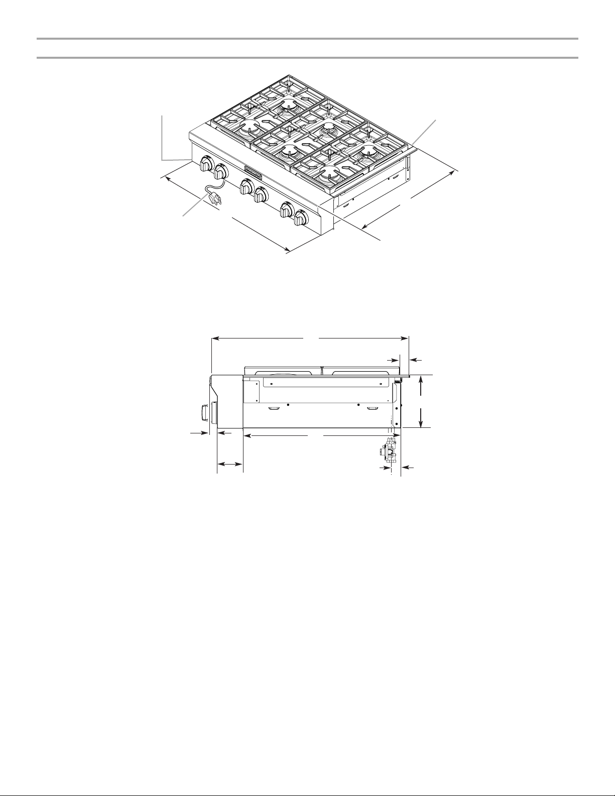
Product Dimensions
Side View of Cooktop
C
B
A. 30" (76.2 cm) cooktop: 29
36" (90.4 cm) cooktop: 35
48" (121.9 cm) cooktop: 47
B. 36" (91.4 cm) long 3 prong grounding-type
power supply cord
A
⁵⁄₈
" (75.1 cm)
⁵⁄₈
" (90.4 cm)
⁵⁄₈
" (120.8 cm)
D
E
C. Model/serial rating plate (located on the
underside of the cooktop burner base)
D. Island trim or optional backguard
E. 27¾" (70.5 cm)
A
B
G
E
F
A. 27¾" (70.5 cm)
B. 1¼" (3.2 cm)
C. 7
⁷⁄₁₆
" (18.8 cm)
D. Gas inlet is located 1
the cooktop burner base and 4
from left-hand side of the cooktop burner base.
⁷⁄₈
" (4.8 cm) from the back of
⁷⁄₈
" (12.4 cm) in
C
D
E. 22" (55.9 cm)
⁵⁄₈
" (9.2 cm)
F. 3
G. 1" (2.6 cm)
5
Page 6
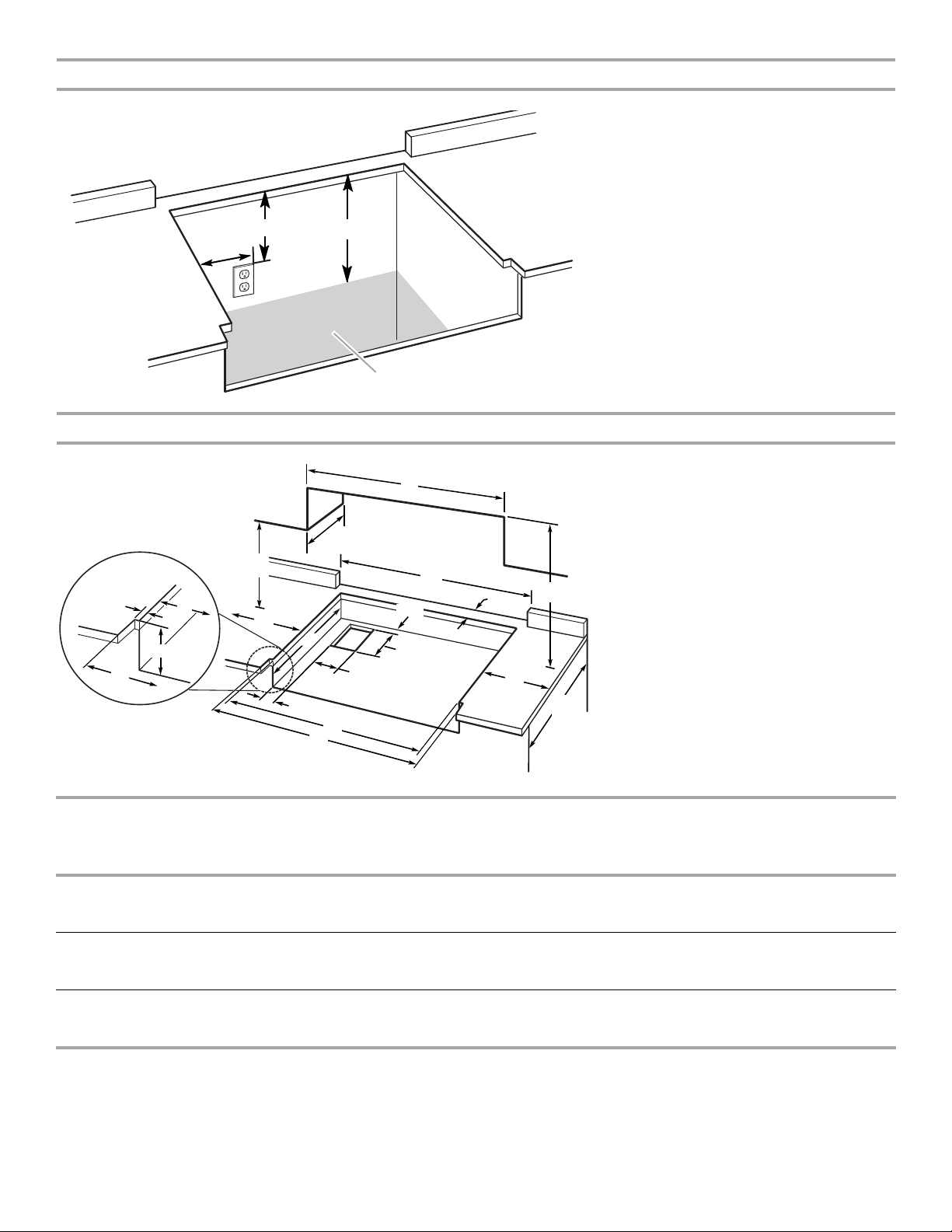
Gas and Electric Connection Locations
B
A
Cabinet Requirements
P
F
O
E
D
L
N
J
K
E
A. Grounded 3-prong outlet should be located on
left-hand side of the cutout 16" (40.6 cm) max.
from enclosure sidewall
B. 10" (25.4 cm) min. clearance from countertop to
top of the outlet
C. 14" (35.6 cm) countertop to the gas supply line
D. Gas supply line should be located in this area on
rear or side walls, or the supply line can come up
C
through the floor.
NOTE: Solid side and bottom of cutout enclosure
not shown.
D
A. See chart.
C
C
G
A**
B min.*
H
I
L
M
D
B. See chart.
C. See chart.
D. See chart.
E. See chart.
F. 18" (45.7 cm) min. clearance upper
cabinet to countertop
³⁄₄
" (1.9 cm) back of cabinet cutout to gas
G.
opening cutout
6⁷⁄₈
" (16.1 cm) gas opening cutout depth
H.
³⁄₄
" (12.1 cm) gas opening cutout width
I. 4
¹⁄₄
" (56.5 cm) cabinet cutout depth
J. 22
K. 2" (5.1 cm) cabinet side to gas cutout
L. 6" (15.2 cm) min. distance on both sides of the
cooktop to the side wall or other combustible
material above cooking surface
M. 24" (61.0 cm) cabinet depth
¹⁄₄
" (18.4 cm) cabinet depth to countertop
N. 7
O. Notch to be equal on both sides
P. 13" (33.0 cm) upper cabinet depth
Size Model A**
Cooktop Cutout
to Back Wall
B*
Cooktop to
Cabinet
C
Optional
Backguard
D
Cabinet and
Countertop
E
Countertop Only
Opening
30" (76.2 cm) KGCU407 1½" (3.8 cm)** 30" (76.2 cm) 30" (76.2 cm) 29¼" (74.3 cm) 30" (76.2 cm) or
29⁷⁄₈" (75.9 cm) for
zero clearance
36" (91.4 cm) KGCU462
KGCU463
KGCU467
48" (121.9 cm) KGCU482
KGCU483
KGCU484
1½" (3.8 cm)**
1¾" (4.4 cm)
1¾" (4.4 cm)
1½" (3.8 cm)**
1¾" (4.4 cm)**
1½" (3.8 cm)**
42" (106.7 cm) 36" (91.4 cm) 35¼"
(89.5 cm)
36" (91.4 cm) or
35⁷⁄₈" (91.1 cm) for
zero clearance
42" (106.7 cm) 48" (121.9 cm) 47¼" (120.0 cm) 48" (121.9 cm) or
47⁷⁄₈" (121.6 cm) for
zero clearance
* NOTES: Dimension “B” can be reduced by 6" (15.2 cm) when bottom of wood or metal cabinet is covered by not less than
0.25" (6.4 mm) flame retardant millboard covered with not less than No. 28 MSG sheet metal, 0.015" (0.4 mm) stainless steel,
0.024" (0.6 mm) aluminum or 0.020" (0.5 mm) copper.
If installing a range hood above the cooktop, follow the range hood instructions for dimensional clearances above the cooktop
surface.
** NOTE: If backwall is constructed of a combustible material and a backguard is not installed, a 3" (7.6 cm) minimum clearance is
required for 48" (121.9 cm) cooktops and cooktops with a grill.
6
Page 7
Electrical Requirements
Gas Supply Requirements
WARNING
Electrical Shock Hazard
Plug into a grounded 3 prong outlet.
Do not remove ground prong.
Do not use an adapter.
Do not use an extension cord.
Failure to follow these instructions can result in death,
fire, or electrical shock.
IMPORTANT: The cooktop must be electrically grounded in
accordance with local codes and ordinances, or in the absence
of local codes, with the National Electrical Code, ANSI/NFPA 70
or Canadian Electrical Code, CSA C22.1.
This cooktop is equipped with an electronic ignition system that
will not operate if plugged into an outlet that is not properly
polarized.
If codes permit and a separate ground wire is used, it is
recommended that a qualified electrical installer determine that
the ground path is adequate.
A copy of the above code standards can be obtained from:
National Fire Protection Association
One Batterymarch Park
Quincy, MA 02269
CSA International
8501 East Pleasant Valley Road
Cleveland, Ohio 44131-5575
■ A 120 volt, 60 Hz, AC only, 15-amp, fused electrical circuit is
required. A time-delay fuse or circuit breaker is also
recommended. It is recommended that a separate circuit
serving only this cooktop be provided.
■ Electronic ignition systems operate within wide voltage limits,
but proper grounding and polarity are necessary. Check that
the outlet provides 120-volt power and is correctly grounded.
■ The wiring diagrams are provided with this cooktop. See
“Wiring Diagrams” section.
WARNING
Explosion Hazard
Use a new CSA International approved gas supply line.
Install a shut-off valve.
Securely tighten all gas connections.
If connected to LP, have a qualified person make sure
gas pressure does not exceed 14" (36 cm) water
column.
Examples of a qualified person include:
licensed heating personnel,
authorized gas company personnel, and
authorized service personnel.
Failure to do so can result in death, explosion, or fire.
Observe all governing codes and ordinances.
IMPORTANT: This installation must conform with all local codes
and ordinances. In the absence of local codes, installation must
conform with American National Standard, National Fuel Gas
Code ANSI Z223.1 - latest edition or CAN/CGA B149 - latest
edition.
IMPORTANT: Leak testing of the cooktop must be conducted
according to the manufacturer’s instructions.
Type of Gas
Natural Gas:
This cooktop is design-certified by CSA International for use with
Natural gas or, after proper conversion, for use with LP gas.
■ This cooktop is factory-set for use with Natural gas. To
convert to LP gas, see the Gas Conversion instructions
provided in the package containing literature. The model/
serial rating plate located on the left underside of the cooktop
burner base has information on the types of gas that can be
used. If the types of gas listed do not include the type of gas
available, check with the local gas supplier.
LP Gas conversion:
Conversion must be done by a qualified service technician.
No attempt shall be made to convert the cooktop from the gas
specified on the model/serial rating plate for use with a different
gas without consulting the serving gas supplier. To convert to LP
gas, use the LP gas conversion kit provided with the cooktop and
see the “Gas Conversions” section.
7
Page 8
Gas Supply Line
Gas Pressure Regulator
■ Provide a gas supply line of ¾" (1.9 cm) rigid pipe to the
cooktop location. A smaller size pipe on longer runs may
result in insufficient gas supply. With LP gas, piping or tubing
size can be ½" (1.3 cm) minimum. Usually, LP gas suppliers
determine the size and materials used in the system.
■ NOTE: Pipe-joint compounds that resist the action of LP gas
must be used. Do not use TEFLON®† tape.
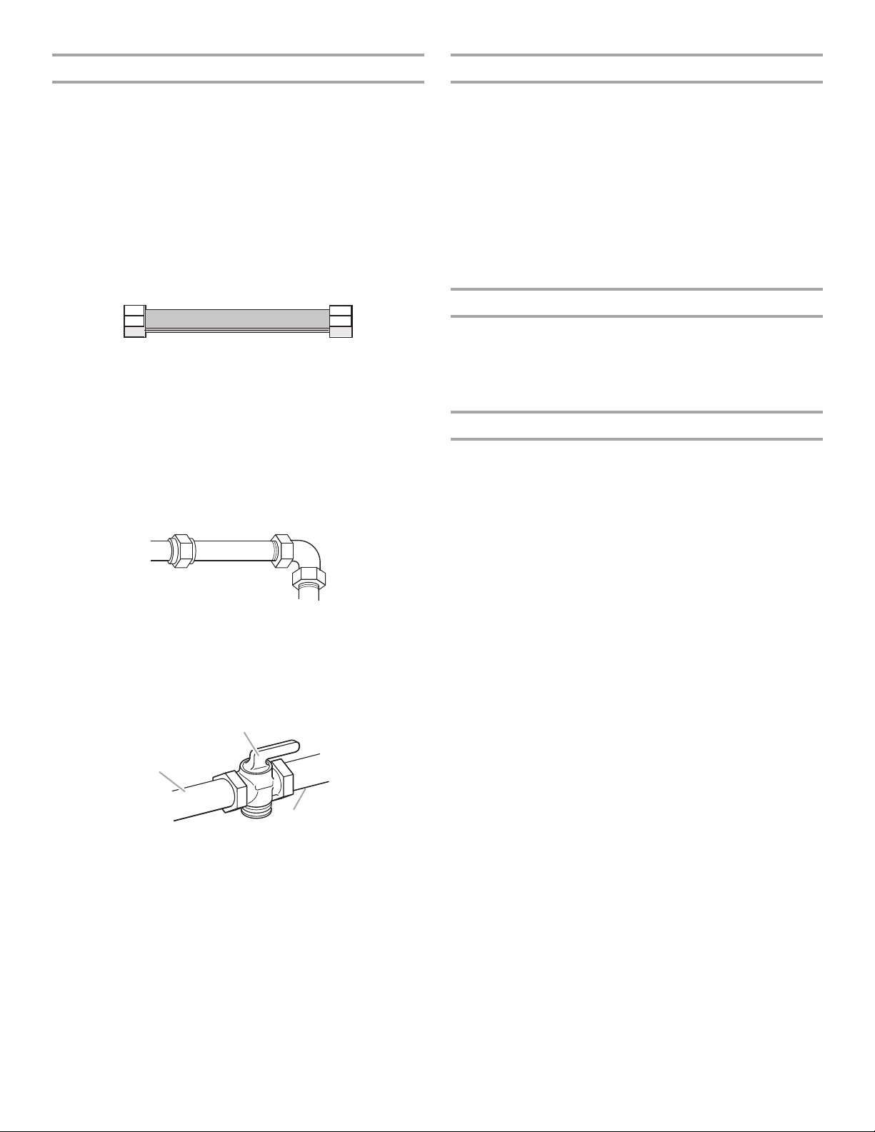
Flexible metal appliance connector:
■ If local codes permit, a new CSA design-certified,
4 - 5 ft (122 - 152.4 cm) long, ⁵⁄₈" (1.6 cm) or
¾" (1.9 cm) I.D., flexible metal appliance connector may
be used for connecting the cooktop to the gas supply
line.
■ A ½" (1.3 cm) male pipe thread is needed for connection
to the female pipe threads of the inlet to the appliance
pressure regulator.
■ Do not kink or damage the flexible metal tubing when
moving the cooktop.
Rigid pipe connection:
The rigid pipe connection requires a combination of pipe
fittings to obtain an in-line connection to the cooktop. The
rigid pipe must be level with the cooktop connection. All
strains must be removed from the supply and fuel lines so
cooktop will be level and in line.
■ Must include a shutoff valve:
The supply line must be equipped with a manual shutoff
valve. This valve should be located in the same room but
external to the cooktop enclosure or cabinet. It should be in a
location that allows ease of opening and closing. Do not
block access to shutoff valve. The valve is for turning on or
shutting off gas to the cooktop.
B
The gas pressure regulator supplied with this cooktop must be
used. The inlet pressure to the regulator should be as follows for
proper operation:
Natural Gas:
Minimum pressure: 6" (15.2 cm) WCP
Maximum pressure: 7" to 14" (17.8 cm to 35.5 cm) WCP
LP Gas:
Minimum pressure: 11" (27.9 cm) WCP
Maximum pressure: 14" (35.5 cm) WCP
Contact local gas supplier if you are not sure about the inlet
pressure.
Burner Input Rating - Altitude
Input ratings shown on the model/serial rating plate are for
elevations up to 2,000 ft (609.6 m).
For elevations above 2,000 ft (609.6 m), ratings need to be
reduced at a rate of 4% for each 1,000 ft (304.8 m) above sea
level (not applicable for Canada).
Gas Supply Pressure Testing
Gas supply pressure for testing regulator must be at least
1" water column pressure above the manifold pressure shown
on the model/serial rating plate.
Line pressure testing above ½ psi gauge (14" WCP)
The cooktop and its individual shutoff valve must be
disconnected from the gas supply piping system during any
pressure testing of that system at test pressures in excess of
½ psi (3.5 kPa).
Line pressure testing at ½ psi gauge (14" WCP) or lower
The cooktop must be isolated from the gas supply piping system
by closing its individual manual shutoff valve during any pressure
testing of the gas supply piping system at test pressures equal to
or less than ½ psi (3.5 kPa).
A
C
A. Gas supply line
B. Shutoff valve “open” position
C. To cooktop
†®TEFLON is a registered trademark of E.I. Du Pont De Nemours and Company.
8
Page 9
INSTALLATION INSTRUCTIONS
C
Install Cooktop
WARNING
Excessive Weight Hazard
Use two or more people to move and install cooktop.
Failure to do so can result in back or other injury.
Write down the model and serial numbers before installing the
cooktop. Both numbers are located on the left front underside of
the cooktop base.
Unpack the parts supplied with your cooktop. The parts shipped
with the cooktop depend on your model ordered. See “Tools and
Parts” section for a complete list parts supplied with your
cooktop.
The pressure regulator and flexible stainless steel gas supply line
connector can be assembled to the cooktop now or after the
cooktop is installed in the cutout. See “Make Gas Connection”
section.
1. Decide on the final location for the cooktop.
2. Using two or more people, place the cooktop upside down
on a covered surface.
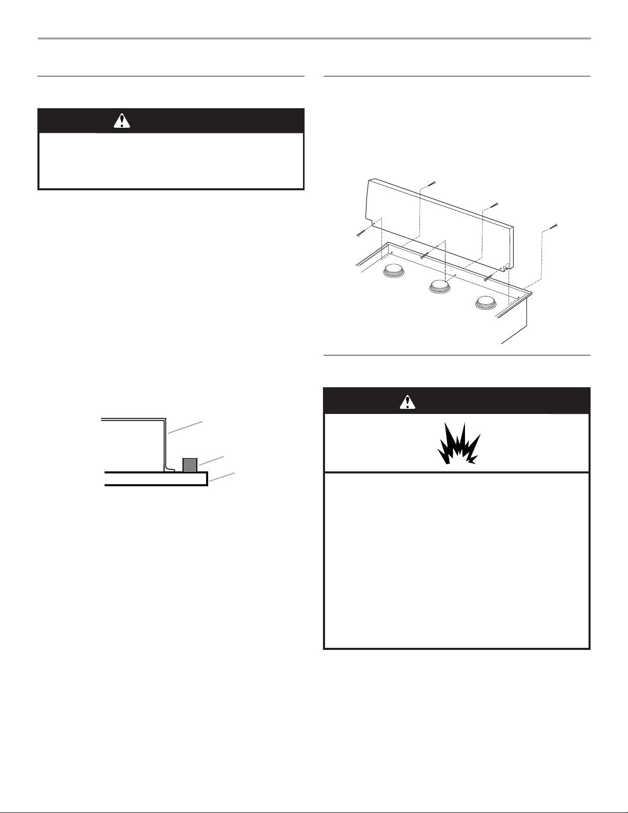
3. Remove foam strip from literature packing. Remove backing
from foam strip. Apply foam strip adhesive-side down around
the side trim.
NOTE: The foam strip helps the cooktop sit flat on uneven
counters and avoids damage to the countertop surface.
A
Install Optional Backguard
36" (91.4 cm) and 48" (121.9 cm) models may require a
backguard. See “Cabinet Dimensions” in the “Location
Requirements” section.
Remove island trim and attach backguard using 6 screws, insert
3 from the front and 3 from the back (9" [22.9 cm] backguard
shown).
Make Gas Connection
WARNING
A. Cooktop base
B. Foam strip
C. Cooktop
4. Turn cooktop right side up.
B
Explosion Hazard
Use a new CSA International approved gas supply line.
Install a shut-off valve.
Securely tighten all gas connections.
If connected to LP, have a qualified person make sure
gas pressure does not exceed 14" (36 cm) water
column.
Examples of a qualified person include:
licensed heating personnel,
authorized gas company personnel, and
authorized service personnel.
Failure to do so can result in death, explosion, or fire.
To Assemble Pressure Regulator:
1. Using 2 or more people, stand the cooktop on its side or
back.
9
Page 10
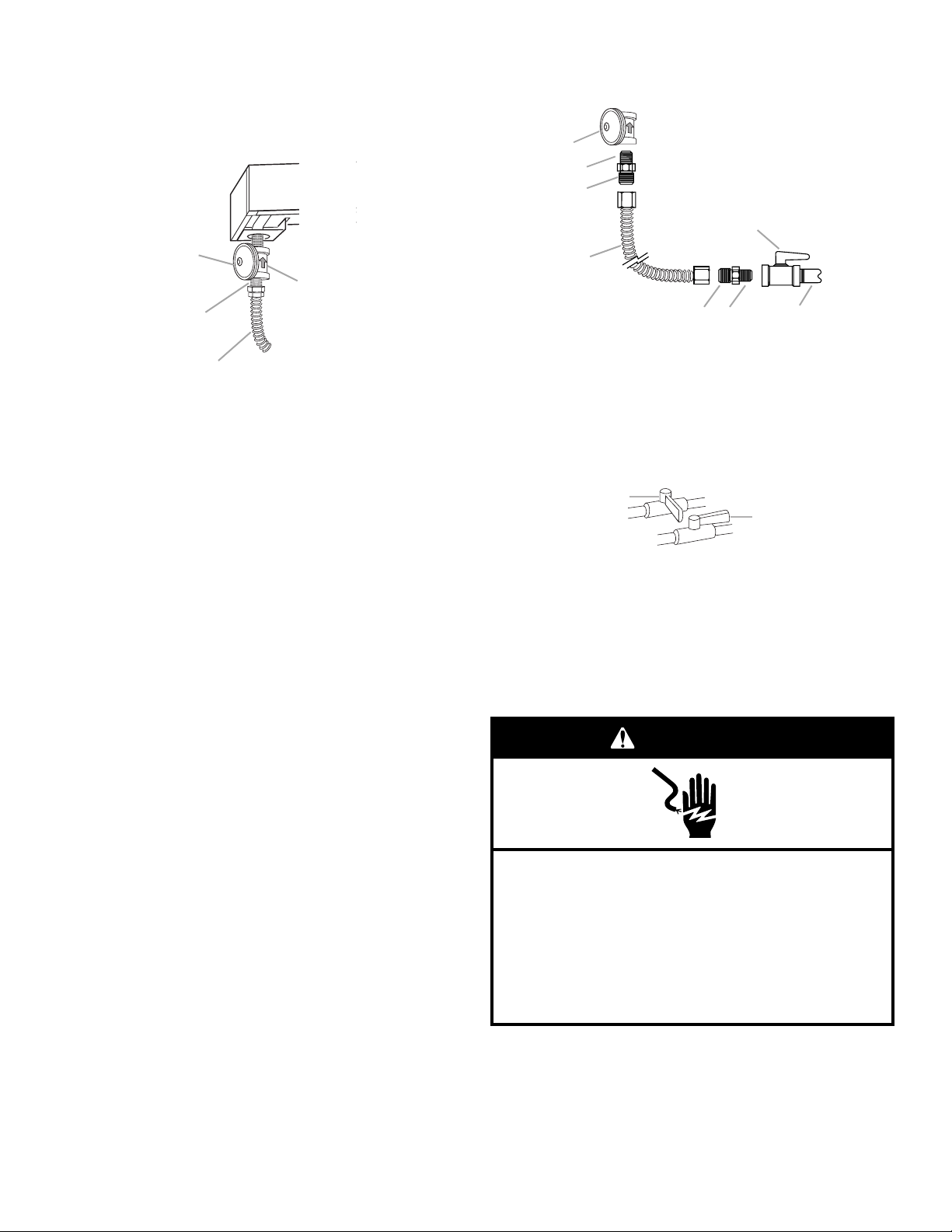
2. Connect the flexible stainless steel connector to the pressure
regulator using a ¹⁄₂" male pipe thread adapter.
A combination of pipe fittings must be used to connect the
cooktop to the existing gas line. Shown following is a typical
connection. Your connection may be different, according to
the supply line type, size and location.
3. Use a ¹⁵⁄₁₆" combination wrench and channel lock pliers to
attach the flexible connector to the adapters. Check that
connector is not kinked.
A
B
C
H
A
B
C
D
A. Gas pressure regulator
B. Regulator - Must be installed with arrow
pointing up to cooktop bottom
C. Adapter - Must have
D. CSA approved flexible stainless steel gas
supply line
¹⁄₂
" male pipe thread
3. Install the pressure regulator with the arrow pointing up
toward the bottom of the cooktop burner base and in a
position where you can reach the regulator cap.
IMPORTANT: All connections must be wrench-tightened. Do
not make connections to the gas regulator too tight. Making
the connections too tight may crack the regulator and cause
a gas leak. Do not allow the regulator to turn on the pipe
when tightening fittings.
Use only pipe-joint compound made for use with Natural and
LP gas. Do not use TEFLON
®
tape.
You will need to determine the fittings required depending on
your installation.
4. Place cooktop into the countertop cutout.
NOTE: Check that the front edge of the cooktop is parallel to
the front edge of the countertop. If repositioning is needed,
lift entire cooktop up from cutout to avoid scratching the
countertop.
D
A. Gas pressure regulator
B. Use pipe-joint compound.
C. Adapter - Must have ½"
male pipe thread
D. Flexible connector
E
F
E. Adapter
F. Use pipe-joint compound.
G. ½" or ¾" gas pipe
H. Manual gas shutoff valve
G
Complete Connection
1. Open the manual shutoff valve in the gas supply line. The
valve is open when the handle is parallel to the gas pipe.
A
B
A. Closed valve
B. Open valve
2. Test all connections by brushing on an approved
noncorrosive leak-detection solution. If bubbles appear, a
leak is indicated. Correct any leak found.
3. Remove surface burner caps and grates from parts package.
Place burner caps on burner bases. Place burner grates over
burners and caps.
WARNING
Typical flexible connection
1. Apply pipe-joint compound made for use with LP gas to the
smaller thread ends of the flexible connector adapters (see B
and F in the following illustration).
2. Attach one adapter to the gas pressure regulator and the
other adapter to the gas shutoff valve. Tighten both adapters.
10
Electrical Shock Hazard
Plug into a grounded 3 prong outlet.
Do not remove ground prong.
Do not use an adapter.
Do not use an extension cord.
Failure to follow these instructions can result in death,
fire, or electrical shock.
4. Plug into a grounded 3 prong outlet.
5. Check the operation of the surface burners. See “Check
Operation of Cooktop Burners” section in the “Complete
Installation” section.
6. If your model has a grill or griddle, see “Install Grill Grease
Trays” or “Install Griddle” section.
Page 11
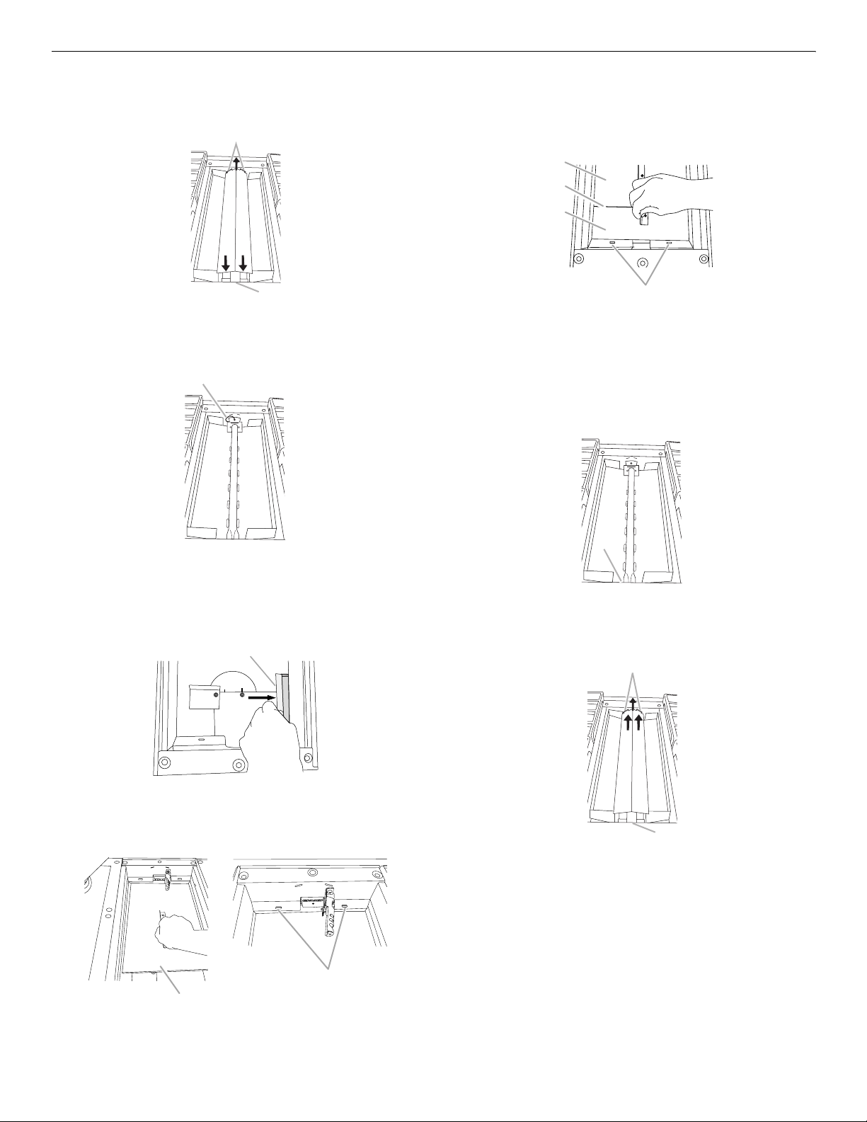
Install Grill Grease Trays (on grill models)
1. Remove flame spreader. Pull forward slightly on the flame
spreader to release the tabs from the rear slots and lift out.
B
6. Insert the small grease tray all the way under the front of the
grill basin and hook it into the slots.
When the 2 grease trays are installed properly, the small
grease tray will hook over the large grease tray.
A
B
C
A
A. Grill front
B. Rear tabs and slots
2. Cut and remove tie strap from rear of burner assembly.
A
A. Tie strap
3. Lift burner assembly up and out to remove.
4. Slide drip tray into opening on the right front side of the grill
basin. There are guides to assure correct placement of the
drip tray.
A
D
A. Large grease tray
B. Grease tray connection
C. Small grease tray
D. Slots
7. Insert the orifice tube on the front of the burner assembly into
the opening at the front of the grill basin and set burner
assembly into place.
A
A. Front opening
8. Insert rear tabs of flame spreader into slots at the rear of the
grill basin, then the front tabs into the front slots.
B
A. Drip tray
5. Insert the large grease tray all the way under the back edge of
the grill basin and hook it into the slots.
B
A
A. Large grease tray
B. Slots
A
A. Front tabs and slots
B. Rear tabs and slots
9. Check the surface burner and grill flames. Refer to
“Electronic Ignition System” in the “Complete Installation”
section.
10. Place the wave tray on top of the flame spreader.
11. Place the grill grate into position.
11
Page 12

Install Griddle
(on griddle models)
The griddle is factory installed.
1. Place drip tray in the well at the front of the griddle. Slide tray
toward the back until it stops.
A
B
Flame Height
The cooktop flame should be a steady blue flame approximately
¼" (0.64 cm) high.
Dual Flame Burner
A
B
A. Upper flame
B. Lower (simmer) flame
Single Flame Burner
A. Griddle drip tray
B. Griddle
2. Clean griddle before using. Refer to the Use and Care Guide.
Complete Installation
Electronic Ignition System
Initial lighting and gas flame adjustments
Cooktop burners use electronic igniters in place of standing
pilots. When the cooktop control knob is turned to any position,
the system creates a spark to light the burner. This sparking
continues, until the flame is lit or the knob is turned to Off.
Check Operation of Cooktop Burners
Push in and turn each control knob to the “LITE” position.
The surface burners and grill flames should light within
4 seconds. The first time a burner is lit it may take longer than
4 seconds to light because of air in the gas line.
After verifying the proper burner operation, turn the control knobs
to OFF.
If burners do not light properly:
■ Turn cooktop control knob to the “OFF” position.
■ Check that the cooktop is plugged in and the circuit breaker
has not tripped or the fuse has not blown.
■ Check that the gas shutoff valves are set to the “open”
position.
■ Check that burner caps are properly positioned on burner
bases.
Repeat start-up. If a burner does not light at this point, contact
your dealer or authorized service company for assistance.
If you need Assistance or Service:
Please reference the “Assistance or Service” section of the Use
and Care Guide or contact the dealer from whom you purchased
your cooktop.
To Adjust Flame Height:
1. Unplug cooktop or disconnect power.
2. Remove burner grates.
3. Remove the control knobs.
4. Pull cooktop forward to expose the control console screws
on the side of the cooktop burner base.
5. Remove the 2 screws on each side of the cooktop burner
base that hold the control console in place.
A
A. Console attachment screws
6. Disconnect wiring from the control console.
On Grill Models:
Support the control console in the middle with one arm and
disconnect the grill indicator light with the other hand.
A
A. Grill indicator light connector
12
Page 13

On Griddle Models:
Support the control console in the middle with one arm and
disconnect the griddle switch connectors and the grill
indicator light with the other hand.
B
A
B. Griddle switch connectors
A. Grill indicator light connector
7. Remove console and set aside.
8. Remove the round gasket from the valve stem.
9. Put a control knob onto the valve stem of the burner you want
to adjust.
13. When finished adjusting the flame height, put a control knob
back onto the valve stem and turn off the burner.
14. Remove the control knob.
15. Replace the round gasket.
16. Repeat steps 8 through 15 for any other burners that need
adjustment.
17. Reinstall the control console. Support the control console in
the middle with one arm and reconnect the griddle switch
connectors and/or grill indicator light connector.
18. Set the control console back into place on the cooktop. For a
proper fit, the flange of the control console must hook over
the lip on the front of the cooktop.
A
B
A. Control console flange
B. Front lip of cooktop
19. Check that the control console is flush with the top edge of
the cooktop.
10. Using a butane extension lighter, turn the control knob to LO
and light the burner.
11. Remove the control knob.
12. Use a ¹⁄₈" x 4¼" flat-blade screwdriver to adjust the flame
height. Tighten screw to reduce flame height. Loosen screw
to increase flame height.
A
A. Single flame burner adjustment screw (on right side of valve)
B. Dual flame burner adjustment screw (on left side of valve)
B
A
A. Flush with top of cooktop
20. Replace the 2 screws on each side of the control console.
21. Push the cooktop back into place in the cutout.
22. Replace the control knobs.
23. Replace burner grates.
24. Plug in cooktop or reconnect power.
25. Test the flame by turning the control from LO to HI, checking
the flame at each setting.
13
Page 14

GAS CONVERSIONS
C
A
C
D
B
IMPORTANT: Gas conversions from Natural gas to LP gas must
be done by a qualified installer.
WARNING
Explosion Hazard
Use a new CSA International approved gas supply line.
Install a shut-off valve.
Securely tighten all gas connections.
If connected to LP, have a qualified person make sure
gas pressure does not exceed 14" (36 cm) water
column.
Examples of a qualified person include:
licensed heating personnel,
authorized gas company personnel, and
authorized service personnel.
Failure to do so can result in death, explosion, or fire.
LP Gas Conversion
1. Turn the manual shutoff valve to the closed position.
2. Unplug cooktop or disconnect power.
B
A
A. To cooktop
B. Shutoff valve (closed position)
C. Gas supply line
.
A
B
CDE
A. Access cap
B. Gasket
C. Gas pressure regulator
3. Test the gas pressure regulator and gas supply line.
The regulator must be checked at a minimum 1" (2.5 cm)
water column above the set pressure. The inlet pressure to
the regulator should be as follows for operation and checking
the regulator setting:
LP Gas:
Minimum pressure 10" (25.4 cm) W.C.
Supply pressure 14" (35.5 cm) W.C.
Gas Supply Pressure Testing
Gas supply pressure for testing regulator must be at least
1" water column pressure above the manifold pressure
shown on the model/serial rating plate.
Line pressure testing above ½ psi gauge (14" WCP)
The cooktop and its individual shutoff valve must be
disconnected from the gas supply piping system during any
pressure testing of that system at test pressures in excess of
½ psi (3.5 kPa).
Line pressure testing at ½ psi gauge (14" WCP) or lower
The cooktop must be isolated from the gas supply piping
system by closing its individual manual shutoff valve during
any pressure testing of the gas supply piping system at test
pressures equal to or less than ½ psi (3.5 kPa).
D. LP position
E. NAT position
To Convert Gas Pressure Regulator
1. Remove the access cap by using a wrench, turning the
access cap counterclockwise.
2. Remove spring retainer from the cap by pushing against the
flat side of the spring retainer. Look at the spring retainer to
locate the “NAT” or “LP” position. Turn over the spring
retainer so the “LP” is showing on the bottom. Snap the
spring retainer back into the cap. Reinstall the cap onto the
regulator
14
To Convert Surface Burners
1. If installed, remove the burner grates.
2. Remove burner cap.
3. Remove the burner head.
NOTE: A ⁷⁄₈" socket must be used to remove the burner head
of the large dual burners.
®
4. Using a T15 Torx
screwdriver, remove the burner base.
Large Dual Burner
A. Burner cap
B. Burner head
C. Gas opening
D. Burner base
Page 15

Medium Burner
A
C
D
B
A
C
A. Burner cap
B. Burner head
C. Gas opening
D. Burner base
Small Burner
A. Burner cap
B
B. Burner head
C. Gas opening
D. Burner base
D
5. Apply masking tape to the end of a 7 mm nut driver to help
hold the gas orifice spud in the nut driver while changing it.
Insert nut driver into gas opening and press down onto the
gas orifice spud and remove by turning the gas orifice spud
counterclockwise and lifting out. Set gas orifice spud aside.
6. Replace with correct LP gas orifice spud. See the “LP Gas
Orifice Spud/Hood Chart.”
Use the following chart to find the exact orifice spud
placement.
LP Gas Orifice Spud/Hood Chart
Burner
Color Size Burner Style
Rating
3,000 BTU NA 0.65 mm Small burners
Replace Igniter - Small Surface Burners Only
1. Unplug igniter wire from electrode.
IMPORTANT: Do not let the igniter wire fall down under the
cooktop surface.
2. Using needle-nose pliers, remove the retaining clip and
spring from the igniter.
B
A
C
A. Retaining clip
B. Spring
C. Natural gas igniter
3. Remove Natural gas igniter from burner base.
4. Place spacer ring onto the LP gas igniter and insert into the
burner base.
A
12,500 BTU Blue 1.04 mm Medium burners
15,500 BTU Yellow
Green
0.93 mm
0.55 mm
Large burner - main
Large burner - simmer
14,500 BTU Black 1.18 mm Grill burner
Burner orifice spud Grill orifice hood
A
A
A. Size stamp or color
A. Size stamp
7. Place Natural gas orifice spuds in plastic parts bag for future
use and keep with package containing literature.
8. For medium and large burners, replace the burner base using
both screws. Replace burner head and cap.
For small burners, replace igniter using the following
instructions.
A. Spacer
5. Insert new spring from LP conversion kit onto the underside
of the igniter and lock into place with the new retaining clip.
B
A
C
A. Retaining clip
B. Spring
C. LP gas igniter
6. Place Natural gas igniter, spring, and clip in plastic parts bag
for future use and keep with package containing literature.
7. Plug in igniter wire.
8. Replace the burner base using both screws.
9. Replace burner head and cap.
To Convert Grill Burner (on some models)
1. Remove grill grate, wave plate, flame spreader and burner
assembly. See “Install Grill Grease Trays” section for removal
instructions. Set parts aside.
15
Page 16

2. Use a ½" deep-well socket to remove the Natural gas orifice
C
A
C
D
B
A
C
D
B
A
C
hood. Replace with correct grill LP gas orifice hood. See “LP
Gas Orifice Spud/Hood Chart.”
A
A. Grill orifice hood location
A
B
3. Turn LP gas orifice hood down tightly onto orifice base.
4. Place Natural gas orifice hoods in plastic parts bag for future
use and keep with package containing literature.
5. Open shutoff valve in the gas supply line. The valve is open
when the handle is parallel to the gas pipe.
REMEMBER: Once you have completed converting the grill,
test the cooktop for leaks by brushing on an approved
noncorrosive leak-detection solution. Bubbles will show,
indicating a leak. Correct any leaks found.
6. Plug in cooktop or reconnect power.
Complete Installation
1. Refer to the “Make Gas Connection” section for properly
connecting the cooktop to the gas supply.
2. Refer to the “Electronic Ignition System” section for proper
burner ignition, operation, and burner flame adjustments.
IMPORTANT: You may have to adjust the “LO” setting for
each cooktop burner.
Checking for proper cooktop burner flame is very important.
The small inner cone should have a very distinct blue flame
¼" (0.64 cm) to ½" (1.3 cm) long. The outer cone is not as
distinct as the inner cone. LP gas flames have a slightly
yellow tip.
3. Refer to “Complete Installation” in the “Installation
Instructions” section of this manual to complete this
procedure.
Natural Gas Conversion
1. Turn manual shutoff valve to the closed position.
2. Unplug cooktop or disconnect power.
B
CDE
A. Access cap
B. Gasket
C. Gas pressure regulator
D. NAT position
E. LP position
To Convert Surface Burners
1. If installed, remove the burner grates.
2. Remove burner cap.
3. Remove the burner head.
NOTE: A ⁷⁄₈" socket must be used to remove the burner head
of the large dual burners.
®
4. Using a T15 Torx
screwdriver, remove the burner base.
Large Dual Burner
A. Burner cap
B. Burner head
C. Gas opening
D. Burner base
Medium Burner
A. Burner cap
B. Burner head
C. Gas opening
D. Burner base
Small Burner
A. Burner cap
B
B. Burner head
C. Gas opening
D. Burner base
D
A
A. To cooktop
B. Shutoff valve (closed position)
C. Gas supply line
To Convert Gas Pressure Regulator
1. Remove the access cap by using a wrench, turning the
access cap counterclockwise.
2. Remove spring retainer from the cap by pushing against the
flat side of the spring retainer. Look at the spring retainer to
locate the “LP” or “NAT” position. Turn over the spring
retainer so the “NAT” is showing on the bottom. Snap the
spring retainer back into the cap. Reinstall the cap onto the
regulator.
16
5. Apply masking tape to the end of a 7 mm nut driver to help
hold the gas orifice spud in the nut driver while changing it.
Insert nut driver into gas opening and press down onto the
gas orifice spud and remove by turning the gas orifice spud
counterclockwise and lifting out. Set gas orifice spud aside.
6. Replace with correct Natural gas orifice spud. See the
“Natural Gas Orifice Spud/Hood Chart.”
Use the following chart to find the exact orifice spud
placement.
Natural Gas Orifice Spud/Hood Chart
Burner Rating Size Burner Style
5,000 BTU 1.01 mm Small burners
Page 17

15,000 BTU 1.75 mm Medium burners
20,000 BTU 1.89 mm
0.69 mm
Large burner - main
Large burner - simmer
18,000 BTU 1.93 mm Grill burner
Burner orifice spud Grill orifice hood
A
A
5. Place LP gas igniter, spacer, spring, and clip in plastic parts
bag for future use and keep with package containing
literature.
6. Plug in igniter wire.
7. Replace the burner base using both screws.
8. Replace burner head and cap.
To Convert Grill Burner (on some models)
1. Remove grill grate, wave plate, flame spreader and burner
assembly. See “Install Grill Grease Trays” section for removal
instructions. Set parts aside.
2. Use a ½" deep-well socket and remove the LP gas orifice
hood. Replace with correct grill Natural gas orifice hood. See
“Natural Gas Orifice Spud/Hood Chart.”
A
A. Size stamp
A. Size stamp
7. Place LP gas orifice spuds in plastic parts bag for future use
and keep with package containing literature.
8. For medium and large burners, replace the burner base using
both screws. Replace burner head and cap.
For small burners, replace igniter using the following
instructions.
Replace Igniter - Small Surface Burners Only
1. Unplug igniter wire from electrode.
IMPORTANT: Do not let the igniter wire fall down under the
cooktop surface.
2. Using needle-nose pliers, remove the retaining clip and
spring from the igniter.
B
A
C
A. Retaining clip
B. Spring
C. LP gas igniter
3. Remove LP gas igniter and spacer from the burner base.
4. Insert Natural gas igniter into burner base. Slide spring onto
the underside of the igniter and lock into place with the
retaining clip.
A. Grill orifice hood location
3. Turn Natural gas orifice hood down tightly onto orifice base.
4. Place LP gas orifice hoods in plastic parts bag for future use
and keep with package containing literature.
5. Open shutoff valve in the gas supply line. The valve is open
when the handle is parallel to the gas pipe.
REMEMBER: Once you have completed converting the grill,
test the cooktop for leaks by brushing on an approved
noncorrosive leak-detection solution. Bubbles will show,
indicating a leak. Correct any leaks found.
6. Plug in cooktop or reconnect power.
Complete Installation
1. Refer to the “Make Gas Connection” section for properly
connecting the cooktop to the gas supply.
2. Refer to the “Electronic Ignition System” section in the
“Complete Installation” section for proper burner ignition,
operation, and burner flame adjustments.
IMPORTANT: You may have to adjust the “LO” setting for
each cooktop burner.
Checking for proper cooktop burner flame is very important.
The small inner cone should have a very distinct blue flame
¼" (0.64 cm) to ½" (1.3 cm) long. The outer cone is not as
distinct as the inner cone. LP gas flames have a slightly
yellow tip.
3. Refer to “Complete Installation” in the “Installation
Instructions” section of this manual to complete this
procedure.
B
A
A. Retaining clip
B. Spring
C. Natural gas igniter
C
17
Page 18

On 30" (76.2 cm) models
WIRING DIAGRAMS
R
R
R
BU
R
BR
R
Y
SW1
Control Input
SW2
SW3
SW4
R
BU
2
1
R
Griddle Spare
Grill Spare
Powe r
Cord
LN
GND
G
Power Cord Only To
Cooktop Stand Alone
Version
W
BK
BK
W
R
W
BK
W
Main - Harness
Power Spare
On 36" (91.4 cm) and 48" (121.9 cm) models
R
R
R
R
R
R
R
R
Griddle Spare
Grill Spare
Powe r
Cord
L
W
BK
BK
W
R
W
N
WR
BK
R
GND
R
R
BU
BR
Y
G
BK
GND
L
N
SW1
SW2
Control Input
SW3
SW4
SW5
SW6
L
N
BR
Electrodes Output
Y
Cooktop
Front View
R
Electrodes Output
BU
BR
Y
G
BK
3
4
21
43
5
6
Cooktop
Front View
18
GND
G
Power Cord Only To
Cooktop Stand Alone
Version
Main - Harness
Power Spare
Page 19

SÉCURITÉ DE LA TABLE DE CUISSON
Votre sécurité et celle des autres est très importante.
Nous donnons de nombreux messages de sécurité importants dans ce manuel et sur votre appareil ménager. Assurez-vous de
toujours lire tous les messages de sécurité et de vous y conformer.
Voici le symbole d’alerte de sécurité.
Ce symbole d’alerte de sécurité vous signale les dangers potentiels de décès et de blessures graves à vous
et à d’autres.
Tous les messages de sécurité suivront le symbole d’alerte de sécurité et le mot “DANGER” ou
“AVERTISSEMENT”. Ces mots signifient :
Risque possible de décès ou de blessure grave si vous ne
DANGER
AVERTISSEMENT
Tous les messages de sécurité vous diront quel est le danger potentiel et vous disent comment réduire le risque de blessure et
ce qui peut se produire en cas de non-respect des instructions.
AVERTISSEMENT : Si les renseignements dans ce manuel ne sont pas exactement
observés, un incendie ou une explosion peut survenir, causant des dommages au
produit, des blessures ou un décès.
suivez pas immédiatement les instructions.
Risque possible de décès ou de blessure grave si vous
ne suivez pas les instructions.
– Ne pas entreposer ni utiliser de l’essence ou d’autres vapeurs ou liquides inflammables
à proximité de cet appareil ou de tout autre appareil électroménager.
– QUE FAIRE DANS LE CAS D’UNE ODEUR DE GAZ :
Ne pas tenter d’allumer un appareil.
•
Ne pas toucher à un commutateur électrique.
•
Ne pas utiliser le téléphone se trouvant sur les lieux.
•
Appeler immédiatement le fournisseur de gaz à partir du téléphone d'un voisin. Suivre
•
ses instructions.
À défaut de joindre votre fournisseur de gaz, appeler les pompiers.
•
– L’installation et l’entretien doivent être effectués par un installateur qualifié, une agence
de service ou le fournisseur de gaz.
AVERTISSEMENT : L’odorat ne permet pas toujours la détection d’une fuite de gaz.
Les distributeurs de gaz recommandent l’emploi d’un détecteur de gaz (homologation UL ou CSA).
Pour d’autre information, contacter le fournisseur de gaz local.
En cas de détection d’une fuite de gaz, exécuter les instructions “Que faire dans le cas d’une odeur de gaz”.
19
Page 20

Dans l’État du Massachusetts, les instructions d’installation suivantes sont applicables :
■ Les travaux d’installation et réparation doivent être exécutés par un plombier ou tuyauteur qualifié ou licencié, ou par le
personnel qualifié d’une entreprise licenciée par l’État du Massachusetts.
■ Si une vanne à boisseau sphérique est utilisée, elle doit comporter une manette “T”.
■ Si un conduit de raccordement flexible est utilisé, sa longueur ne doit pas dépasser 3 pi.
EXIGENCES D’INSTALLATION
Outillage et pièces
Rassembler les outils et composants nécessaires avant
d’entreprendre l’installation. Lire et observer les instructions
fournies avec chacun des outils de la liste ci-dessous.
Outillage nécessaire
■ Clé à molette
■ Mètre-ruban
■ Marqueur ou crayon
■ Clé à tuyauterie
■ Tournevis à lame plate
■ Clé mixte de 15/16"
■ Clé ou pince
■ Composé d’étanchéité
des raccords filetés –
résistant au gaz propane
■ Solution non-corrosive de
détection des fuites
Pour conversions pour
gaz propane/naturel
■ Tournevis Torx
■ Clé à molette
■ Clé à cliquet de ³⁄₈"
■ Douille de ⁷⁄₈"
■ Douille longue de ½"
■ Tourne-écrou de 7 mm
■ Ruban adhésif de
masquage
®†
T15
Pièces fournies
Vérifier que toutes les pièces sont présentes.
■ Détendeur
■ Grilles de brûleur
■ Chapeaux de brûleur
■ Grille du gril (sur modèles avec gril)
■ Plateau ondulé (sur modèles avec gril)
■ Répartiteur de flammes (sur modèles avec gril)
■ Ensemble de brûleur (sur modèles avec gril)
■ Plateaux à graisse (2) (sur modèles avec gril)
■ Plateau d'égouttement de la plaque à frire (sur modèles avec
plaque à frire)
■ Plateau d'égouttement du gril (sur modèles avec gril)
■ Ruban de mousse
■ Ensemble de gicleurs pour gaz propane (W10221288)
■ Étiquette de conversion (8302139)
REMARQUE : La table de cuisson est conçue pour une
utilisation au gaz naturel. Pour effectuer une conversion au gaz
propane, voir la section “Conversions de gaz”.
Pièces nécessaires
Il est possible que les modèles de 36" (91,4 cm) et
48" (121,9 cm) doivent être installés avec un dosseret.
Voir “Dimensions du placard” dans la section “Exigences
d’emplacement”.
■ Dosseret rétractable de 36" (91,4 cm)
Commander la pièce numéro 8284756
■ Dosseret rétractable de 48" (121,9 cm)
Commander la pièce numéro 8284755
■ Dosseret de 9" (22,9 cm) pour tables de cuisson de
36" (91,4 cm)
Commander la pièce numéro W10115776
■ Dosseret de 9" (22,9 cm) pour tables de cuisson de
48" (121,9 cm)
Commander la pièce numéro W10115777
■ Dosseret de 22" (55,9 cm) avec tablette pour tables de
cuisson de 36" (91,4 cm)
Commander la pièce numéro W10225949
■ Dosseret de 22" (55,9 cm) avec tablette pour tables de
cuisson de 48" (121,9 cm)
Commander la pièce numéro W10225948
Pour commander, voir la section “Assistance ou service” du
Guide d’utilisation et d’entretien.
Vérifier les codes locaux et consulter le fournisseur de gaz.
Vérifier l'alimentation en gaz et l'alimentation électrique
existantes. Voir les sections “Spécifications électriques” et
“Spécifications de l'alimentation en gaz”.
Conversion pour utilisation en haute altitude
Pour convertir la table de cuisson pour des altitudes supérieures
à 6 560 pi (1999,5 m), commander un ensemble pour conversion
en haute altitude.
■ Pièce numéro W10237848 - gaz propane pour haute altitude
■ Pièce numéro W10160841 - gaz naturel pour haute altitude
Pour commander, voir la section “Assistance ou service” du
Guide d’utilisation et d’entretien.
20
†®TORX est une marque déposée de Acument Intellectual Properties, LLC
Page 21

Exigences d'emplacement
IMPORTANT : Observer les dispositions de tous les codes et
règlements en vigueur. Ne pas obstruer le flux de combustion et
de ventilation.
■ C'est à l'installateur qu'incombe la responsabilité de
respecter les distances de séparation exigées pour
l'installation, spécifiées sur la plaque signalétique de
l'appareil. La plaque signalétique des numéros de modèle et
de série est située sur la face inférieure de la base de brûleur
de la table de cuisson.
■ Il est recommandé qu'une hotte de cuisinière de 600 CFM ou
plus soit installée au-dessus de la table de cuisson.
■ Il n'est pas recommandé de monter un ensemble four à
hotte/micro-ondes au-dessus de la table de cuisson.
■ La table de cuisson doit être installée dans un emplacement à
l’écart des zones de forts courants d’air, telles que fenêtres,
portes et évents ou ventilateurs de chauffage.
■ Toutes les ouvertures dans le mur ou le plancher de
l'emplacement d'installation de la table de cuisson doivent
être scellées.
■ Respecter les dimensions indiquées pour les ouvertures à
découper dans les placards. Ces dimensions constituent les
valeurs minimales des dégagements de séparation.
■ Une source d'électricité avec liaison à la terre est nécessaire.
Voir la section “Spécifications électriques”.
■ Une source de gaz adéquate doit être disponible. Voir la
section “Spécifications de l'alimentation en gaz”.
■ De par sa conception, la table de cuisson est suspendue sur
le plan de travail, par les rebords des côtés ou de l'arrière.
■ Les sources de gaz et d'électricité doivent être situées tel
qu'indiqué à la section “Emplacements des raccordements
au gaz et à l'électricité”, pour qu'elles soient accessibles et
qu'il ne soit pas nécessaire d'enlever la table de cuisson.
■ Prévoir une ouverture dans l'angle arrière gauche de
l'enceinte – voir l'illustration – pour le passage de la
canalisation de gaz et du câble d'alimentation électrique et
pour que l'étiquette signalétique soit visible.
IMPORTANT : Afin d'éviter d’endommager les placards,
consulter le constructeur de la maison ou le fabricant des
placards pour déterminer si les matériaux utilisés peuvent subir
un changement de couleur, une déstratification ou d'autres
dommages.
Résidence mobile – Spécifications additionnelles à
respecter lors de l'installation
L'installation de cette table de cuisson doit être conforme aux
dispositions de la norme Manufactured Home Construction and
Safety Standard, Title 24 CFR, Part 3280 (anciennement Federal
Standard for Mobile Home Construction and Safety, Title 24,
HUD Part 280). Lorsque cette norme n'est pas applicable, utiliser
la norme Standard for Manufactured Home Installations, ANSI
A225.1/NFPA 501A ou respecter les dispositions des codes
locaux.
Au Canada, l'installation de cette table de cuisson doit satisfaire
aux stipulations de la version la plus récente de la norme CAN/
CSA-A240 ou des codes locaux en vigueur.
Dimensions du produit
A. Table de cuisson de 30" (76,2 cm) : 29
Table de cuisson de 36" (90,4 cm) : 35
Table de cuisson de 48" (121,9 cm) : 47
B. Cordon d'alimentation à 3 broches pour liaison à la
terre de 36" (91,4 cm) de long
C
D
E
B
A
⁵⁄₈
" (75,1 cm)
⁵⁄₈
" (90,4 cm)
⁵⁄₈
" (120,8 cm)
C. La plaque signalétique des numéros de modèle
et de série est située sur la face inférieure de la
base de brûleur de la table de cuisson.
D. Garniture d'îlot ou dosseret facultatif
E. 27¾" (70,5 cm)
21
Page 22

Vue latérale de la table de cuisson
A
B
C
G
F
A. 27¾" (70,5 cm)
B. 1¼" (3,2 cm)
⁷⁄₁₆
" (18,8 cm)
C. 7
D. L'entrée de gaz se trouve à 1
de la base du brûleur de la table de cuisson et à 4
(12,4 cm) du côté intérieur gauche de la base du
brûleur de la table de cuisson.
⁷⁄₈
" (4,8 cm) de l'arrière
Emplacements des raccordements au gaz et à l'électricité
B
A
C
E
D
E. 22" (55,9 cm)
F. 3
⁵⁄₈
" (9,2 cm)
G. 1" (2,6 cm)
⁷⁄₈
"
A. La prise de courant à 3 alvéoles reliée à la terre
doit se trouver du côté gauche de l'ouverture
découpée, à 16" (40,6 cm) max. de la paroi
latérale de l'encastrement
B. Dégagement minimal de 10" (25,4 cm) à partir du
plan de travail jusqu'au sommet de la sortie
C. 14" (35,6 cm) entre le plan de travail et la
canalisation d'alimentation en gaz
D. La canalisation d'alimentation en gaz doit se
trouver dans cette zone sur les murs arrière ou
latéraux; la canalisation d’alimentation en gaz
peut aussi ressortir à travers le plancher.
REMARQUE : Le côté plein et le fond de l'ouverture
ne sont pas illustrés.
D
22
Page 23

Spécifications du placard
O
E
D
N
C
P
F
C
G
L
J
H
I
K M
D
E
A**
L
B min.*
A. Voir le tableau.
B. Voir le tableau.
C. Voir le tableau.
D. Voir le tableau.
E. Voir le tableau.
F. 18" (45,7 cm) min. de dégagement entre
le placard supérieur et le plan de travail
³⁄₄
" (1,9 cm) entre l'arrière de l'ouverture
G.
découpée dans le placard et l'ouverture
découpée pour la canalisation de gaz.
6⁷⁄₈
" (16,1 cm) de profondeur pour l'ouverture
H.
découpée pour la canalisation de gaz
I. 4
³⁄₄
" (12,1 cm) de largeur pour l'ouverture
découpée pour la canalisation de gaz
J. 22
¹⁄₄
" (56,5 cm) de profondeur de l'ouverture
découpée dans le placard
K. 2" (5,1 cm) entre le côté du placard et
l'ouverture découpée pour la canalisation de
gaz
L. Dégagement de 6" (15,2 cm) min. entre les deux côtés
de la table de cuisson et les parois latérales ou
d'autres matériaux combustibles
de la surface de cuisson.
M. Profondeur de placard 24" (61,0 cm)
¹⁄₄
" (18,4 cm) de profondeur entre placard et
N. 7
plan de travail
O. L'encoche doit être la même des deux côtés
P. Profondeur des placards supérieurs : 13" (33,0 cm)
situés au-dessus
Taille Modèle A**
Ouverture
découpée pour la
table de cuisson
B*
Entre la table
de cuisson et
le placard
C
Ouverture pour
dosseret
facultatif
D
Placard et plan
de travail
E
Plan de travail
uniquement
jusqu'au mur
arrière
30" (76,2 cm) KGCU407 1½" (3,8 cm)** 30" (76,2 cm) 30" (76,2 cm) 29¼" (74,3 cm) 30" (76,2 cm) ou
29⁷⁄₈" (75,9 cm) pour
un dégagement nul
36" (91,4 cm) KGCU462
KGCU463
KGCU467
48" (121,9 cm) KGCU482
KGCU483
KGCU484
1½" (3,8 cm)**
1¾" (4,4 cm)
1¾" (4,4 cm)
1½" (3,8 cm)**
1¾" (4,4 cm)**
1½" (3,8 cm)**
42" (106,7 cm) 36" (91,4 cm) 35¼"
(89,5 cm)
36" (91,4 cm) ou
35⁷⁄₈" (91,1 cm) pour
un dégagement nul
42" (106,7 cm) 48" (121,9 cm) 47¼" (120 cm) 48" (121,9 cm) ou
47⁷⁄₈" (121,6 cm) pour
un dégagement nul
* REMARQUES : La dimension “B” peut être réduite de 6" (15,2 cm) lorsque le fond d'un placard de bois ou de métal est couverte par
une planche ignifugée d'au moins 0,25" (6,4 mm) recouverte d'une feuille métallique d'épaisseur égale ou supérieure à : acier calibre
28 MSG, acier inoxydable 0,015" (0,4 mm), aluminium 0,024" (0,6 mm), ou cuivre 0,020" (0,5 mm).
En cas d'installation d'une hotte au-dessus de la table de cuisson, suivre les instructions fournies avec la hotte concernant les
dimensions de dégagement à respecter au-dessus de la surface de la table de cuisson.
** REMARQUE : Si le dosseret est fabriqué à partir d'un matériau combustible et qu'aucun dosseret n'est installé, un dégagement
minimal de 3" (7,6 cm) est nécessaire pour des tables de cuisson de 48" (121,9 cm) et tables de cuisson équipées d'un gril.
23
Page 24

Spécifications électriques
Spécifications de l'alimentation en gaz
AVERTISSEMENT
Risque de choc électrique
Brancher sur une prise à 3 alvéoles reliée à la terre.
Ne pas enlever la broche de liaison à la terre.
Ne pas utiliser un adaptateur.
Ne pas utiliser un câble de rallonge.
Le non-respect de ces instructions peut causer
un décès, un incendie ou un choc électrique.
IMPORTANT : La table de cuisson doit être correctement reliée à
la terre en conformité avec les codes et règlements locaux en
vigueur, ou en l'absence de tels codes, avec le National Electrical
Code, ANSI/NFPA 70 ou le Code canadien des installations
électriques, CSA C22.1.
Cette table de cuisson est dotée d'un système d'allumage
électronique qui ne fonctionnera pas en cas de branchement
dans une prise qui n'est pas correctement polarisée.
Si les codes le permettent et si on utilise un conducteur distinct
de liaison à la terre, il est recommandé qu'un électricien qualifié
vérifie la qualité de la liaison à la terre.
Pour obtenir un exemplaire de la norme des codes ci-dessus,
contacter :
National Fire Protection Association
One Batterymarch Park
Quincy, MA 02269
CSA International
8501 East Pleasant Valley Road
Cleveland, OH 44131-5575
■ L'appareil doit être alimenté par un circuit de 120 V, CA
seulement, 60 Hz, 15 ampères, protégé par fusible. On
recommande également d'utiliser un fusible ou un disjoncteur
temporisé. Il est recommandé de raccorder la table de
cuisson sur un circuit distinct exclusif à cet appareil.
■ Les systèmes d'allumage électronique fonctionnent avec des
limites de tension étendues, mais une liaison à la terre
correcte et une polarité appropriée sont nécessaires. Vérifier
que la prise fournit une alimentation de 120 V et qu'elle est
correctement reliée à la terre.
■ Les schémas de câblage sont fournis avec cette table de
cuisson. Voir la section “Schémas de câblage”.
AVERTISSEMENT
Risque d'explosion
Utiliser une canalisation neuve d'arrivée de gaz
approuvée par la CSA International.
Installer un robinet d'arrêt.
Bien serrer chaque organe de connexion de la
canalisation de gaz.
En cas de connexion au gaz propane, demander à une
personne qualifiée de s'assurer que la pression de gaz
ne dépasse pas 36 cm (14 po) de la colonne d'eau.
Par personne qualifiée, on comprend :
le personnel autorisé de chauffage,
le personnel autorisé d'une compagnie de gaz, et
le personnel d'entretien autorisé.
Le non-respect de ces instructions peut causer
un décès, une explosion ou un incendie.
Observer les dispositions de tous les codes et règlements en
vigueur.
IMPORTANT : L'installation doit satisfaire aux critères de tous les
codes et règlements locaux. En l'absence de code local,
l'installation doit satisfaire aux prescriptions de la plus récente
édition du code national en vigueur : American National
Standard, National Fuel Gas Code ANSI Z223.1 ou CAN/CGA
B149.
IMPORTANT : Les tests de fuite de la table de cuisson doivent
être effectués selon les instructions du fabricant.
Type de gaz
Gaz naturel :
La conception de cette table de cuisson a été homologuée par
CSA International pour l'alimentation au gaz naturel, ou pour
l'alimentation au propane après conversion adéquate.
■ Cette table de cuisson a été configurée à l'usine pour
l'alimentation au gaz naturel. Pour effectuer la conversion
pour une alimentation au propane, voir les instructions de
conversion de gaz fournies dans le sachet de documentation.
La plaque signalétique des numéros de modèle et de série
située sur la face inférieure (à gauche) de la boîte de brûleur
indique les types de gaz utilisables. Si le type de gaz
disponible n'est pas mentionné sur la plaque signalétique,
consulter le fournisseur local.
24
Page 25

Conversion pour l'alimentation au propane :
L'opération de conversion doit être exécutée par un technicien
de réparation qualifié.
Ne pas entreprendre de convertir la table de cuisson pour
l'utilisation d'un gaz différent de celui indiqué sur la plaque
signalétique sans d'abord consulter le fournisseur de gaz. Pour la
conversion au propane, utiliser le kit de conversion au gaz
propane fourni avec la table de cuisson et consulter la section
“Conversions pour changement de gaz”.
Canalisation de gaz
■ Installer une canalisation de gaz rigide de ¾" (1,9 cm) jusqu'à
l'emplacement d'installation de la table de cuisson. L'emploi
d'une canalisation de plus petit diamètre ou plus longue peut
causer une déficience du débit d'alimentation. Pour
l'alimentation au propane, le diamètre des canalisations doit
être de ½" ou plus. En général, le fournisseur de gaz propane
détermine les matériaux à utiliser et le diamètre approprié.
■ REMARQUE : On doit utiliser un composé d'étanchéité des
tuyauteries résistant à l'action du gaz propane. Ne pas utiliser
de ruban TEFLON
Raccord métallique flexible :
■ Si les codes locaux le permettent, utiliser un connecteur à
gaz flexible en acier inoxydable de ⁵⁄₈", conçu par CSA
pour raccorder la table de cuisson à la canalisation rigide
d'alimentation en gaz.
■ Un raccord avec filetage mâle de ½" (1,3 cm) est
nécessaire pour la connexion sur le raccord à filetage
femelle à l'entrée du détendeur de la table de cuisson.
■ Ne pas déformer/écraser/endommager le tube métallique
flexible lors d'un déplacement de la table de cuisson.
Raccordement par un ensemble rigide :
On doit utiliser une combinaison de raccords pour réaliser un
raccordement rigide entre la table de cuisson et la
canalisation de gaz. Le tuyau rigide doit se trouver au même
niveau que le raccord de connexion de la table de cuisson.
On doit veiller à ne soumettre les sections de canalisation
d'alimentation à aucun effort de traction ou flexion pour que
la table de cuisson soit d'aplomb et correctement alignée.
†
®
.
■ Robinet d'arrêt nécessaire :
La canalisation d'alimentation doit comporter un robinet
d'arrêt manuel. Le robinet d'arrêt manuel doit être séparé de
la table de cuisson, mais doit se trouver dans la même pièce.
La canalisation doit se trouver en un endroit facilement
accessible pour les manœuvres d'ouverture/fermeture. Ne
pas entraver l'accès au robinet d'arrêt manuel. Le robinet
d'arrêt manuel est prévu pour ouvrir ou fermer l'alimentation
en gaz de la table de cuisson.
B
A
C
A. Canalisation de gaz
B. Robinet d'arrêt manuel - position d'ouverture
C. Vers table de cuisson
Détendeur
Le détendeur fourni avec cette table de cuisson doit être utilisé.
La pression d'alimentation du détendeur doit être comme suit
pour un fonctionnement correct :
Gaz naturel :
Pression minimum : 6" (15,2 cm) (colonne d'eau)
Pression maximum : 7" à 14" (17,8 cm à 35,5 cm) (colonne d'eau)
Gaz propane :
Pression minimum : 11" (27,9 cm) (colonne d'eau)
Pression maximum : 14" (35,5 cm) (colonne d'eau)
En cas d'incertitude quant à la pression d'alimentation à établir,
contacter le fournisseur de gaz local.
Caractéristiques d'alimentation du brûleur
Les débits thermiques indiqués sur la plaque signalétique
correspondent à une altitude d'utilisation inférieure à 2000 pi
(609,6 m).
Lorsque l'appareil est utilisé à une altitude supérieure à 2000 pi
(609,6 m), on doit réduire le débit thermique indiqué de 4 % pour
chaque tranche de 1000 pi (304,8 m) au-dessus du niveau de la
mer (non applicable au Canada).
†®TEFLON est une marque déposée de E.I. Du Pont De Nemours and Company.
Test de pressurisation de la canalisation de gaz
On doit tester le détendeur sous une pression supérieure d’au
moins 1" (colonne d'eau) à la pression de la tubulure de
distribution indiquée sur la plaque signalétique.
Pressurisation à une pression supérieure à ½ lb/po²
(14" - colonne d'eau)
Lors de tout test de pressurisation de ce système à une pression
supérieure à ½ lb/po² (3,5 kPa), on doit déconnecter la table de
cuisson et son robinet d'arrêt individuel de la canalisation de gaz.
Pressurisation à une pression relative de ½ lb/po²
(14" - colonne d'eau) ou moins
Lors de tout test de pressurisation de la canalisation de gaz à une
pression égale ou inférieure à ½ lb/po² (3,5 kPa), on doit isoler la
table de cuisson de la canalisation de gaz par fermeture de son
robinet d'arrêt manuel individuel.
25
Page 26

INSTRUCTIONS D’INSTALLATION
C
Installation de la table de cuisson
AVERTISSEMENT
Risque du poids excessif
Utiliser deux ou plus de personnes pour déplacer et
installer la table de cuisson.
Le non-respect de cette instruction peut causer
une blessure au dos ou d'autre blessure.
Prendre note des numéros de modèle et de série avant d'installer
la table de cuisson. Les deux numéros sont situés sur la partie
inférieure avant gauche de la base du brûleur.
Déballer les pièces fournies avec la table de cuisson. Les pièces
expédiées avec la table de cuisson dépendent du modèle
commandé. Voir la section “Outillage et pièces” pour une liste
complète des pièces fournies avec la table de cuisson.
Le détendeur et le connecteur de la canalisation de gaz flexible
en acier inoxydable peuvent être raccordés à la table de cuisson
maintenant ou après l'installation de la table de cuisson dans
l'ouverture. Voir la section “Raccordement au gaz”.
1. Déterminer l’emplacement final de la table de cuisson.
2. À l'aide de deux personnes ou plus, placer la table de
cuisson à l'envers sur une surface couverte.
3.
Enlever la bande de mousse du sachet de documentation.
Retirer l'endos de la bande de mousse. Appliquer le côté
adhésif de la bande de mousse le long de la garniture latérale.
REMARQUE : La bande de mousse aide la table de cuisson
à rester à plat sur des comptoirs irréguliers et permet d'éviter
d'endommager la surface de la surface du plan de travail.
A
Installation du dosseret facultatif
Il est possible que les modèles de 36" (91,4 cm) et de
48" (121,9 cm) nécessitent un dosseret. Voir “Dimensions du
placard” dans la section “Exigences d’emplacement”. Voir la
section “Outillage et pièces” pour des renseignements sur la
commande.
Ôter la garniture périphérique et fixer le dosseret à l'aide de 6 vis;
insérer 3 vis à l'avant et 3 en partant de l'arrière (dosseret illustré
de 9" [22,9 cm]).
Raccordement au gaz
AVERTISSEMENT
B
A. Base de la table de cuisson
B. Bande de mousse
4. Tourner le côté droit de la table de cuisson vers le haut.
C. Table de cuisson
Risque d'explosion
Utiliser une canalisation neuve d'arrivée de gaz
approuvée par la CSA International.
Installer un robinet d'arrêt.
Bien serrer chaque organe de connexion de la
canalisation de gaz.
En cas de connexion au gaz propane, demander à une
personne qualifiée de s'assurer que la pression de gaz
ne dépasse pas 36 cm (14 po) de la colonne d'eau.
Par personne qualifiée, on comprend :
le personnel autorisé de chauffage,
le personnel autorisé d'une compagnie de gaz, et
le personnel d'entretien autorisé.
Le non-respect de ces instructions peut causer
un décès, une explosion ou un incendie.
Assemblage du détendeur :
1. Placer la table de cuisson en appui sur le côté ou la face
arrière; avec l’aide de deux personnes ou plus.
2. Connecter le raccord flexible d'acier inoxydable au détendeur
- utiliser un raccord d'adaptation comportant un filetage mâle
de ½" (NPT).
26
Page 27

On doit utiliser une combinaison de raccords de tuyauterie
pour raccorder la table de cuisson à l'alimentation en gaz
existante. On voit ci-dessous une illustration d'un
raccordement typique. Le raccordement peut varier, selon le
type d'alimentation, la dimension et l'emplacement.
3. Utiliser une clé mixte de ¹⁵⁄₁₆" et une pince multiprise pour
fixer le raccord flexible sur les raccords d'adaptation. Veiller à
ne pas déformer/écraser le raccord flexible.
A
B
C
A
B
C
D
A. Détendeur
B. Détendeur - Doit être installé avec la flèche pointant
vers le haut (vers le fond de la table de cuisson).
C. Raccord d'adaptation - avec filetage mâle NPT ½"
D. Canalisation flexible d'alimentation en gaz (acier
inoxydable) approuvée par la CSA
3. Orienter la flèche du détendeur vers le haut, vers le fond de la
boîte des brûleurs et de telle manière que le chapeau du
détendeur soit accessible.
IMPORTANT : Tous les raccords doivent être bien serrés à
l'aide d'une clé. Ne pas serrer excessivement la connexion
sur le détendeur. Un serrage excessif pourrait provoquer une
fissuration du détendeur et une fuite de gaz. Lors du serrage
d'un raccord, empêcher le détendeur de tourner sur le tuyau.
Utiliser uniquement un composé d'étanchéité des tuyauteries
conçu pour l'utilisation avec le gaz naturel ou le propane. Ne
pas utiliser de ruban TEFLON
®
.
Il sera nécessaire de choisir les raccords à utiliser en fonction
de la configuration d'installation.
4. Placer la table de cuisson dans l'ouverture prévue à cet effet.
REMARQUE : Vérifier que le bord avant de la table de
cuisson est parallèle au bord avant du plan de travail. S'il est
nécessaire de repositionner la table de cuisson, la soulever
entièrement pour la retirer de l'ouverture découpée afin
d'aviter les égratignures.
Raccordement typique par raccord flexible
1. Appliquer un composé d'étanchéité des filetages résistant au
propane sur l'extrémité filetée la plus petite des adaptateurs
de raccord flexible (voir C et F ci-dessous).
2. Fixer un raccord d'adaptation sur le régulateur de pression du
gaz et l'autre raccord d'adaptation sur le robinet d'arrêt de la
canalisation de gaz. Serrer les deux raccords d'adaptation.
H
D
A. Détendeur
B. Appliquer un composé
d'étanchéité.
C. Raccord d'adaptation - avec
filetage mâle NPT de ½"
D. Raccord flexible
E
F
E. Appliquer un composé
d'étanchéité.
F. Raccord d'adaptation
G. Tuyau de gaz de ½" ou ¾"
H. Robinet d'arrêt manuel
G
Compléter le raccordement
1. Ouvrir le robinet d'arrêt manuel sur la canalisation de gaz. Le
robinet est ouvert lorsque la manette est parallèle à la
canalisation.
A
B
A. Robinet fermé
B. Robinet ouvert
2. Vérifier tous les raccordements en les badigeonnant d'une
solution de détection des fuites non corrosive approuvée.
L'apparition de bulles indique une fuite. Réparer toute fuite
éventuelle.
3. Ôter les chapeaux de brûleur de surface et les grilles du
sachet de pièces. Aligner les encoches des chapeaux de
brûleur avec les broches dans la base de chaque brûleur.
Placer les grilles de brûleur sur les brûleurs et chapeaux.
AVERTISSEMENT
Risque de choc électrique
Brancher sur une prise à 3 alvéoles reliée à la terre.
Ne pas enlever la broche de liaison à la terre.
Ne pas utiliser un adaptateur.
Ne pas utiliser un câble de rallonge.
Le non-respect de ces instructions peut causer
un décès, un incendie ou un choc électrique.
4. Brancher sur une prise à 3 alvéoles reliée à la terre.
27
Page 28

5. Vérifier le fonctionnement des brûleurs de surface. Consulter
la section “Vérification du fonctionnement des brûleurs de
surface”, dans la section “Achever l’installation”.
6. Si votre modèle a été expédié avec un gril ou une plaque à
frire, consulter la section “Installation du gril” ou “Installation
de la plaque à frire”.
Installation des plateaux à graisse du gril
(sur les modèles de gril)
1. Ôter le répartiteur de flammes. Tirer le répartiteur de flammes
légèrement vers l'avant pour libérer les onglets des encoches
arrière et le soulever.
B
A
A. Avant du gril
B. Onglets et encoches arrière
5. Insérer complètement le grand plateau à graisse sous le
rebord arrière du bac du gril et l'engager dans les encoches.
B
A
A. Grand plateau à graisse
B. Encoches
6. Insérer complètement le petit plateau à graisse sous le rebord
avant du bac du gril et l'engager dans les encoches.
Lorsque les 2 plateaux à graisse sont correctement installés,
le petit plateau à graisse s’emboîte sur le grand plateau à
graisse.
A
B
C
2. Couper et retirer l'attache de fixation de l'arrière de
l'ensemble de brûleur.
A
A. Attache de fixation
3. Soulever l'ensemble de brûleur et le tirer vers l'extérieur pour
l'extraire.
4. Faire glisser le plateau d'égouttement dans l'ouverture du
côté droit du bac du gril. Il y a des guides pour s'assurer de la
position correcte du plateau d'égouttement.
A
D
A. Grand plateau à graisse
B. Connexion du plateau à
graisse
C. Petit plateau à graisse
D. Encoches
7. Insérer le tube de l'orifice à l'avant de l'ensemble de brûleur,
dans l'ouverture située à l'avant du bac du gril et mettre
l'ensemble de brûleur en place.
A
A. Ouverture avant
28
A. Plateau d'égouttement
Page 29

8. Insérer les onglets arrière du répartiteur de flammes dans les
encoches à l'arrière du bac du gril et les onglets avant dans
les encoches avant.
Contrôle du fonctionnement des brûleurs de la table de
cuisson
B
A
A. Onglets et encoches avant
B. Onglets et encoches arrière
9. Contrôler les flammes sur les brûleurs du gril et de la table de
cuisson. Consulter la section “Système d'allumage
électronique” dans la section “Achever l’installation”.
10. Placer le plateau ondulé par-dessus le répartiteur de
flammes.
11. Mettre la grille de gril en position.
Installation de la plaque à frire
(sur modèles de plaque à frire)
La plaque à frire est installée à l’usine.
1. Placer le plateau d’égouttement dans la cavité à l’avant de la
plaque à frire. Faire glisser le plateau vers l’arrière jusqu'à la
position de butée.
Enfoncer et tourner chaque bouton de commande à la position
“LITE”.
Les brûleurs de surface et les flammes du gril doivent s'allumer
en 4 secondes. La première fois que l'on allume un brûleur, il peut
prendre plus de 4 secondes pour s'allumer à cause de l'air se
trouvant dans la canalisation de gaz.
Après avoir vérifié le bon fonctionnement du brûleur, tourner les
boutons de commande à “OFF” (arrêt).
Si les brûleurs ne s'allument pas correctement :
■ Tourner le bouton de commande de la table de cuisson à la
position “OFF” (arrêt).
■ Vérifier que la table de cuisson est branchée, que le
disjoncteur ne s'est pas déclenché et qu'aucun fusible n'est
grillé.
■ Vérifier que chaque robinet d'arrêt est à la position “open”
(ouverture).
■ Vérifier que les chapeaux de brûleurs sont correctement
placés sur la base des brûleurs.
Répéter le processus de mise en marche. Si à ce stade un
brûleur ne s'allume pas, contacter le revendeur ou un dépanneur
agréé.
Si vous avez besoin d’assistance ou de service :
Consulter la section “Assistance ou service” du Guide
d'utilisation et d'entretien ou contacter le marchand chez qui
vous avez acheté votre table de cuisson.
Hauteur de flamme
A
B
A. Plateau d'égouttement de la plaque à frire
B. Plaque à frire
2. Nettoyer la plaque à frire avant de l'utiliser. Consulter le Guide
d’utilisation et d’entretien.
Achever l'installation
Système d'allumage électronique
Allumage initial et réglages des flammes de gaz
À la place de flammes de veille, les brûleurs de la table de
cuisson sont dotés d'allumeurs électroniques. Lorsqu'on place le
bouton de commande de la table de cuisson à n'importe quelle
position, le système génère une étincelle pour allumer le brûleur.
Les étincelles continuent d'être générées jusqu'à ce que la
flamme soit allumée ou que l'on tourne le bouton à Off.
La flamme de la table de cuisson doit correspondre à une flamme
bleue stable d'environ ¼" (0,64 cm) de hauteur.
Brûleur à double flamme
A
B
A. Débit thermique maximum
B. Débit thermique minimum (flamme de mijotage)
Brûleur à flamme simple
Réglage de la taille des flammes :
1. Débrancher la table de cuisson ou déconnecter la source de
courant électrique.
2. Ôter les grilles de brûleur.
3. Ôter les boutons de commande.
4. Tirer la table de cuisson vers l'avant pour découvrir les vis de
la console de commande situées sur le côté de la base du
brûleur de la table de cuisson.
29
Page 30

5. Ôter les 2 vis situées de chaque côté de la base du brûleur de
la table de cuisson qui maintiennent la console de commande
en place.
A
A. Vis de fixation de la console
6. Déconnecter le câblage de la console de commande.
Sur les modèles de gril :
Soutenir la console de commande par le milieu avec un bras
et déconnecter le témoin lumineux du gril avec l'autre main.
10. À l'aide d'un allumeur à butane avec extension, tourner le
bouton de commande à LO (basse) et allumer le brûleur.
11. Ôter le bouton de commande.
12. Régler la hauteur de flamme à l'aide d'un tournevis à lame
plate de ¹⁄₈" x 4¼". Serrer la vis pour réduire la hauteur de la
flamme. Desserrer la vis pour augmenter la hauteur de
flamme.
A
A. Connecteur du témoin lumineux du gril
Sur les modèles avec plaque à frire :
Soutenir la console de commande par le milieu avec un bras
et déconnecter les connecteurs du commutateur de la plaque
à frire et le témoin lumineux du gril avec l'autre main.
B
A
B. Connecteurs du commutateur de la
plaque à frire
A. Connecteur du témoin lumineux du gril
A
A. Vis de réglage du brûleur à flamme simple (du côté
droit du robinet)
B. Vis de réglage du brûleur à double flamme (du côté
gauche du robinet)
B
13. Lorsque l'on a terminé de régler la hauteur de flamme,
replacer le bouton de commande sur la tige de réglage du
robinet et éteindre le brûleur.
14. Ôter le bouton de commande.
15. Remettre en place le joint circulaire.
16. Répéter les étapes 8 à 15 pour tout autre brûleur nécessitant
un réglage.
17. Réinstaller la console de commande. Soutenir la console de
commande par le milieu avec un bras et reconnecter les
connecteurs du commutateur de la plaque à frire et/ou le
connecteur du témoin lumineux du gril.
18. Remettre la console de commande en place sur la table
cuisson. Pour que les deux soient bien emboîtées, le rebord
de la console de commande doit se rabattre par-dessus la
bordure avant de la table de cuisson.
7. Retirer la console et la mettre de côté.
8. Ôter le joint circulaire de la tige de réglage du robinet.
9. Placer un bouton de commande sur la tige de réglage du
brûleur que l'on souhaite régler.
30
A
B
A. Rebord de la console de commande
B. Bordure avant de table de cuisson de
cuisinière
Page 31

19. Vérifier que la console de commande est en affleurement
C
avec le bord supérieur de la table de cuisson.
A
A. En affleurement avec le dessus de
la table de cuisson
CONVERSIONS POUR CHANGEMENT DE GAZ
IMPORTANT : L'opération de conversion de l'appareil (pour
l'alimentation au gaz propane au lieu du gaz naturel) doit être
exécutée par un installateur qualifié.
AVERTISSEMENT
20. Remettre en place les 2 vis de chaque côté de la console de
commande.
21. Repousser la table de cuisson vers l'arrière pour la remettre
en place dans l'ouverture découpée.
22. Réinstaller les boutons de commande.
23. Réinstaller les grilles des brûleurs.
24. Brancher la table de cuisson ou reconnecter la source de
courant électrique.
25. Tester la flamme en tournant le bouton de commande pour le
faire passer de la position “LO” (basse) à la position “HI”
(élevée) et observer les flammes pour chaque réglage.
Conversion du détendeur
1. Utiliser une clé pour enlever le chapeau de l'ouverture
d'accès; faire tourner le chapeau dans le sens antihoraire.
2. Ôter le ressort de retenue qui se trouve sous le chapeau -
pousser contre le côté plat du ressort de retenue. Examiner le
ressort de retenue pour identifier la position “NAT” ou “LP”.
Orienter correctement le ressort de retenue pour que la
mention “LP” soit au fond. Réinstaller le ressort de retenue
dans le chapeau. Réinstaller le chapeau sur le détendeur.
Risque d'explosion
Utiliser une canalisation neuve d'arrivée de gaz
approuvée par la CSA International.
Installer un robinet d'arrêt.
Bien serrer chaque organe de connexion de la
canalisation de gaz.
En cas de connexion au gaz propane, demander à une
personne qualifiée de s'assurer que la pression de gaz
ne dépasse pas 36 cm (14 po) de la colonne d'eau.
Par personne qualifiée, on comprend :
le personnel autorisé de chauffage,
le personnel autorisé d'une compagnie de gaz, et
le personnel d'entretien autorisé.
Le non-respect de ces instructions peut causer
un décès, une explosion ou un incendie.
Conversion pour l'alimentation au propane
1. Tourner le robinet d'arrêt manuel pour le placer à la position
de fermeture.
2. Débrancher la table de cuisson ou déconnecter la source de
courant électrique.
B
A
B
CDE
A. Chapeau de
l'ouverture d'accès
B. Joint d'étanchéité
C. Détendeur
3. Tester le détendeur et la canalisation de gaz.
On doit tester le détendeur sous une pression supérieure d’au
moins 1" (2,5 cm) (colonne d'eau) à la pression de réglage.
Pour le fonctionnement et le contrôle du réglage du
détendeur, il faut que la pression d'admission au détendeur
corresponde aux indications ci-dessous :
Gaz propane :
Pression minimale de 10" (25,4 cm) (colonne d'eau)
Pression de service de 14" (35,5 cm) (colonne d'eau)
D. Position LP
E. Position NAT
A
A. Vers la table de cuisson
B. Robinet d'arrêt (position de
fermeture)
C. Canalisation d'alimentation en gaz
31
Page 32

Test de pressurisation de la canalisation de gaz
A
C
A
C
D
B
A
C
On doit tester le détendeur sous une pression supérieure
d’au moins 1" (colonne d'eau) à la pression de la tubulure de
distribution indiquée sur la plaque signalétique.
Pressurisation à une pression supérieure à ½ lb/po² (14" –
colonne d'eau)
Pour tout test de pressurisation du système à une pression
supérieure à ½ lb/po² (3,5 kPa), on doit déconnecter la table
de cuisson et son robinet d'arrêt des canalisations
d'alimentation en gaz à pressuriser.
Pressurisation à une pression de ½ lb/po² (14" – colonne
d'eau) ou moins
La table de cuisson devra être isolée des canalisations
d'alimentation en gaz par la fermeture du robinet d'arrêt
manuel individuel durant tout test de pressurisation des
canalisations d'alimentation en gaz à une pression égale ou
inférieure à ½ lb/po² (3,5 kPa).
Conversion des brûleurs de surface
Tableau de sélection des gicleurs/injecteurs femelles pour gaz
propane
Puissance
thermique
Couleur
Taille Style de brûleur
3 000 BTU S/O 0,65 mm Petits brûleurs
12 500 BTU Bleu 1,04 mm Brûleurs moyens
15 500 BTU Jaune
Vert
0,93 mm
0,55 mm
Gros brûleur - principal
Gros brûleur - mijotage
1. Enlever les grilles de brûleur si elles sont installées.
2. Ôter le chapeau de brûleur.
3. Ôter la tête de brûleur.
REMARQUE : On doit utiliser une douille de ⁷⁄₈" pour retirer la
tête de brûleur des gros brûleurs à double flamme.
®
4. Utiliser un tournevis Torx
T15 pour enlever la base du
brûleur.
Gros brûleur à double flamme
A. Chapeau de brûleur
B
D
B
B. Tête de brûleur
C. Ouverture de gaz
D. Base du brûleur
Brûleur moyen
A. Chapeau de brûleur
B. Tête de brûleur
C. Ouverture de gaz
D. Base du brûleur
Petit brûleur
A. Chapeau de brûleur
B. Tête de brûleur
C. Ouverture de gaz
D. Base du brûleur
D
5. Appliquer du ruban adhésif de masquage à l'extrémité d’un
tourne-écrou de 7 mm pour retenir le gicleur du brûleur dans
le tourne-écrou durant l’extraction. Insérer le tourne-écrou
dans l'ouverture de gaz, appuyer sur le gicleur et le retirer en
le faisant tourner dans le sens antihoraire et en le soulevant.
Conserver à part le gicleur du brûleur.
6. Remplacer le gicleur par un gicleur pour gaz propane de taille
correcte. Voir le “Tableau de sélection des gicleurs/injecteurs
femelles pour gaz propane”.
Suivre les indications du tableau ci-dessous pour pouvoir
déterminer l'emplacement exact de chaque gicleur de
brûleur.
14 500 BTU Noir 1,18 mm Brûleur du gril
Gicleur de brûleur Injecteur femelle du gril
A
A
A. Marquage ou couleur pour
identification de la taille
A. Marquage pour identification
de la taille
7. Placer les gicleurs pour gaz naturel dans le sachet de pièces
en plastique et les conserver avec le sachet de
documentation, pour pouvoir les réutiliser ultérieurement.
8. Pour les brûleurs moyens et gros, réinstaller la base du
brûleur à l'aide des deux vis. Réinstaller la tête et le chapeau
de brûleur.
Pour les petits brûleurs, remplacer l'allumeur à l'aide des
instructions suivantes.
Remplacement de l'allumeur - Petits brûleurs de surface
uniquement
1. Débrancher le conducteur de l'allumeur de l'électrode.
IMPORTANT: Ne pas laisser le conducteur de l'allumeur
tomber sous la surface de la table de cuisson.
2. À l'aide de pinces à pointe biseautée, retirer l'attache de
retenue et le ressort de l'allumeur.
B
A
C
A. Attache de retenue
B. Ressort
C. Allumeur pour gaz naturel
32
Page 33

3. Retirer l'allumeur pour gaz naturel de la base du brûleur.
C
4. Placer la rondelle d'espacement sur l'allumeur pour gaz
propane et l'insérer dans la base du brûleur.
A
A. Rondelle d’espacement
5. Insérer le nouveau ressort dans l'ensemble de conversion
pour gaz propane sur le dessous de l'allumeur et le fixer à
l'aide de la nouvelle attache de retenue.
B
A
C
A. Attache de retenue
B. Ressort
C. Allumeur pour gaz propane
6. Placer l'allumeur pour gaz naturel, le ressort et l'attache dans
le sachet de pièces en plastique et les conserver avec le
sachet de documentation, pour pouvoir les réutiliser
ultérieurement.
7. Brancher le conducteur de l'allumeur.
8. Réinstaller la base du brûleur à l'aide des deux vis.
9. Réinstaller la tête et le chapeau de brûleur.
Conversion du brûleur du gril (sur certains modèles)
1. Ôter la grille du gril, le plateau ondulé, le répartiteur de
flamme et l'ensemble de brûleur. Voir la section “Installation
des plateaux à graisse du gril” pour des instructions sur la
dépose. Conserver les pièces à part.
2. Retirer l'injecteur femelle pour gaz naturel à l'aide d'une
douille longue de ½". Remplacer le gicleur par un injecteur
femelle de gaz propane pour gril de taille correcte. Voir le
“Tableau de sélection des gicleurs/injecteurs femelles pour
gaz propane”.
4. Placer les injecteurs femelles pour gaz naturel dans le sachet
de pièces en plastique et les conserver avec le sachet de
documentation, pour pouvoir les réutiliser ultérieurement.
5. Ouvrir le robinet d'arrêt de la canalisation de gaz. Le robinet
est ouvert lorsque la manette est parallèle à la canalisation de
gaz.
NE PAS OUBLIER : Après avoir exécuté la conversion du gril,
effectuer un test de recherche des fuites au niveau de la table
de cuisson : appliquer une solution de détection des fuites
homologuée non corrosive. La formation de bulles identifie
une fuite. Veiller à éliminer toute fuite détectée.
6. Brancher la table de cuisson ou reconnecter la source de
courant électrique.
Achever l'installation
1. Consulter la section “Raccordement au gaz” pour le
raccordement correct de la table de cuisson à la canalisation
d'alimentation en gaz.
2. Pour l'allumage et l'utilisation corrects du brûleur ainsi que le
réglage des flammes sur le brûleur, voir la section “Système
d'allumage électronique” de la section “Achever
l’installation”.
IMPORTANT : Il peut être nécessaire de modifier le réglage
des flammes à la position du débit thermique minimum (“LO”)
pour chaque brûleur de la table de cuisson.
Il est très important de vérifier l’établissement de flammes
correctes sur les brûleurs de la table de cuisson. Le petit
cône interne doit comporter une flamme bleue très distincte
de ¼" (0,64 cm) à ½" (1,3 cm) de longueur. Le cône externe
n'est pas aussi disctinct que le cône interne. Les flammes
d'un brûleur alimenté au propane comportent une pointe
légèrement jaune.
3. Voir le paragraphe “Achever l'installation” de la section
“Instructions d'installation” du présent manuel pour achever
ce processus.
Conversion pour l'alimentation au gaz naturel
1. Fermer le robinet d'arrêt manuel.
2. Débrancher la table de cuisson ou déconnecter la source de
courant électrique.
B
A
A
A. Emplacement de l’injecteur femelle du gril
3. Tourner l’injecteur femelle pour gaz propane vers le bas
jusqu'à ce qu'il soit bien serré contre la base de l’injecteur.
A. Vers la table de cuisson
B. Robinet d'arrêt (position de fermeture)
C. Canalisation d'alimentation en gaz
33
Page 34

Conversion du détendeur
A
C
A
C
D
B
A
C
1. Utiliser une clé pour enlever le chapeau de l'ouverture
d'accès; faire tourner le chapeau dans le sens antihoraire.
2. Ôter le ressort de retenue qui se trouve sous le chapeau -
pousser contre le côté plat du ressort de retenue. Examiner le
ressort de retenue pour identifier la position “LP” ou “NAT”.
Orienter correctement le ressort de retenue pour que la
mention “NAT” soit au fond. Réinstaller le ressort de retenue
dans le chapeau. Réinstaller le chapeau sur le détendeur.
.
A
B
CDE
A. Chapeau de
l'ouverture d'accès
B. Joint d'étanchéité
C. Détendeur
D. Position NAT
E. Position LP
5. Appliquer du ruban adhésif de masquage à l'extrémité d’un
tourne-écrou de 7 mm pour retenir le gicleur du brûleur dans
le tourne-écrou durant l’extraction. Insérer le tourne-écrou
dans l'ouverture de gaz, appuyer sur le gicleur et le retirer en
le faisant tourner dans le sens antihoraire et en le soulevant.
Conserver à part le gicleur du brûleur.
6. Remplacer le gicleur par un gicleur pour gaz naturel de taille
correcte. Voir le “Tableau de sélection des gicleurs/injecteurs
femelles pour gaz naturel”.
Suivre les indications du tableau ci-dessous pour pouvoir
déterminer l'emplacement exact de chaque gicleur de
brûleur.
Tableau de sélection des gicleurs/injecteurs femelles pour gaz
propane
Puissance
Taille Style de brûleur
thermique
5 000 BTU 1,01 mm Petits brûleurs
15 000 BTU 1,75 mm Brûleurs moyens
20 000 BTU 1,89 mm
0,69 mm
Gros brûleur - principal
Gros brûleur - mijotage
Conversion des brûleurs de surface
1. Enlever les grilles de brûleur si elles sont installées.
2. Ôter le chapeau de brûleur.
3. Ôter la tête de brûleur.
REMARQUE : On doit utiliser une douille de ⁷⁄₈" pour retirer la
tête de brûleur des gros brûleurs à double flamme.
4. Utiliser un tournevis Torx® T15 pour enlever la base du
brûleur.
Gros brûleur à double flamme
A. Chapeau de brûleur
B
D
B
B. Tête de brûleur
C. Ouverture de gaz
D. Base du brûleur
Brûleur moyen
A. Chapeau de brûleur
B. Tête de brûleur
C. Ouverture de gaz
D. Base du brûleur
Petit brûleur
A. Chapeau de brûleur
B. Tête de brûleur
C. Ouverture de gaz
D. Base du brûleur
18 000 BTU 1,93 mm Brûleur du gril
Gicleur de brûleur Injecteur femelle du gril
A
A
A. Marquage pour identification
de la taille
A. Marquage pour identification
de la taille
7. Placer les gicleurs pour propane dans le sachet de pièces en
plastique et avec les documents fournis avec l'appareil, pour
pouvoir les réutiliser ultérieurement.
8. Pour les brûleurs moyens et gros, réinstaller la base du
brûleur à l'aide des deux vis. Réinstaller la tête et le chapeau
de brûleur.
Pour les petits brûleurs, remplacer l'allumeur à l'aide des
instructions suivantes.
34
D
Page 35

Remplacement de l'allumeur - Petits brûleurs de surface
uniquement
1. Débrancher le conducteur de l'allumeur de l'électrode.
IMPORTANT : Ne pas laisser le conducteur de l'allumeur
tomber sous la surface de la table de cuisson.
2. À l'aide de pinces à pointe biseautée, retirer l'attache de
retenue et le ressort de l'allumeur.
B
A
Conversion du brûleur du gril (sur certains modèles)
1. Ôter la grille du gril, le plateau ondulé, le répartiteur de
flamme et l'ensemble de brûleur. Voir la section “Installation
des plateaux à graisse du gril” pour des instructions sur la
dépose. Conserver les pièces à part.
2. Retirer l’injecteur femelle pour gaz propane à l'aide d'une
douille longue de ½". Remplacer le gicleur par un injecteur
femelle pour gaz naturel pour gril de taille correcte. Voir le
“Tableau de sélection des gicleurs/injecteurs femelles pour
gaz propane”.
C
A. Attache de retenue
B. Ressort
C. Allumeur pour gaz propane
3. Retirer l'allumeur pour gaz propane et la rondelle
d'espacement de la base du brûleur.
4. Retirer l'allumeur pour gaz naturel de la base du brûleur. Faire
glisser le ressort sur le dessous de l'allumeur et le fixer à
l'aide de l'attache de retenue.
B
A
C
A. Attache de retenue
B. Ressort
C. Allumeur pour gaz naturel
5. Placer l'allumeur pour gaz propane, la rondelle
d'espacement, le ressort et l'attache dans le sachet de
pièces en plastique et les conserver avec le sachet de
documentation, pour pouvoir les réutiliser ultérieurement.
6. Brancher le conducteur de l'allumeur.
7. Réinstaller la base du brûleur à l'aide des deux vis.
8. Réinstaller la tête et le chapeau de brûleur.
A
A. Emplacement de l'injecteur femelle du gril
3. Tourner l’injecteur femelle pour gaz naturel vers le bas jusqu'à
ce qu'il soit bien serré contre la base de l’injecteur.
4. Placer les injecteurs femelles pour gaz propane dans le
sachet de pièces en plastique et les conserver avec le sachet
de documentation, pour pouvoir les réutiliser ultérieurement.
5. Ouvrir le robinet d'arrêt de la canalisation de gaz. Le robinet
est ouvert lorsque la manette est parallèle à la canalisation de
gaz.
NE PAS OUBLIER : Après avoir exécuté la conversion du gril,
effectuer un test de recherche des fuites au niveau de la table
de cuisson : appliquer une solution de détection des fuites
homologuée non corrosive. La formation de bulles identifie
une fuite. Veiller à éliminer toute fuite détectée.
6. Brancher la table de cuisson ou reconnecter la source de
courant électrique.
Achever l'installation
1. Consulter la section “Raccordement au gaz” pour le
raccordement correct de la table de cuisson à la canalisation
d'alimentation en gaz.
2. Pour l'allumage et l'utilisation corrects du brûleur ainsi que le
réglage des flammes sur le brûleur, voir la section “Système
d'allumage électronique”, dans la section “Achever
l’installation”.
IMPORTANT : Il peut être nécessaire de modifier le réglage
des flammes à la position du débit thermique minimum (“LO”)
pour chaque brûleur de la table de cuisson.
Il est très important de vérifier l’établissement de flammes
correctes sur les brûleurs de la table de cuisson. Le petit
cône interne doit comporter une flamme bleue très distincte
de ¼" (0,64 cm) à ½" (1,3 cm) de longueur. Le cône externe
n'est pas aussi disctinct que le cône interne. Les flammes
d'un brûleur alimenté au propane comportent une pointe
légèrement jaune.
3. Voir le paragraphe “Achever l'installation” de la section
“Instructions d'installation” du présent manuel pour achever
ce processus.
35
Page 36

Sur les modèles de 30" (76,2 cm)
©
SCHÉMAS DE CÂBLAGE
R
R
R
BU
R
MAR
R
JA
SW1
Entrée de commande
SW2
SW3
SW4
R
BU
2
1
R
Source secondaire
pour la plaque
chauffante
Source secondaire
pour le gril
Cordon
d'alimentation
LN
Terre
G
Cordon d'alimentation
uniquement à la version
de la table de cuisson autonome
R
BL
N
N
BL
R
BL
N
BL
Faisceau principal
Alimentation secondaire
Terre
R
Sur les modèles de 36" (91,4 cm) et 48" (121,9 cm)
R
R
R
R
R
R
R
Source secondaire
pour la plaque à frire
Source secondaire
pour le gril
Cordon
d'alimentation
L
R
BL
N
N
BL
R
BL
N
BL R
N
Terre
R
BU
MAR
JA
VE
N
L
N
MAR
Sortie des électrodes
JA
Vue de face
de la table
de cuisson
R
SW1
SW2
Sortie des électrodes
Entrée de commande
SW3
SW4
SW5
SW6
L
N
BU
MAR
JA
VE
N
Vue de face
de la table
de cuisson
3
4
21
43
5
6
Faisceau principal
Alimentation secondaire
Printed in U.S.A.
Imprimé aux É.-U.
1/09
W10191877A
2009. All rights reserved.
Tous droits réservés.
Terre
G
Cordon d'alimentation
uniquement à la version
de la table de cuisson autonome
® Marque déposée/TM Marque de commerce de KitchenAid, U.S.A., Emploi sous licence par KitchenAid Canada au Canada
® Registered Trademark/TM Trademark of KitchenAid, U.S.A., KitchenAid Canada licensee in Canada
 Loading...