

KitchenAid KGCT305BWH0 Installation Instructions Manual
,..
LE.’
Instructions d’installation
Surfaces de cuisson
vitrifiees &
a2
de 76,2 cm
7
30 po) et
91,4 cm (36 PO),
avec brfileurs scell&
IMPORTANT:
Lire et conserver
ces instructions.
IMPORTANT:
lnstallateur : Remettre les instructions d’installation au
propri6taire.
Propriktaire : Conserver les instructions d’installation
pour reference ultbrieure.
Conserver les instructions d’installation pour utilisation
par I’inspecteur local des installations Blectriques.
Pike no 3188087 Rev. B
,..
<E.;
Installation Instructions
30” (76.2cm) and
36” (91.4cm) Gas
Sealed Burner
Glass Cooktops
IMPORTANT:
Read and save these
instructions.
IMPORTANT:
Installer: Leave Installation Instructions with the
homeowner.
Homeowner: Keep Installation Instructions for future
reference.
Save Installation Instructions for local electrical
inspector’s use.
Part No. 3188087 Rev. B
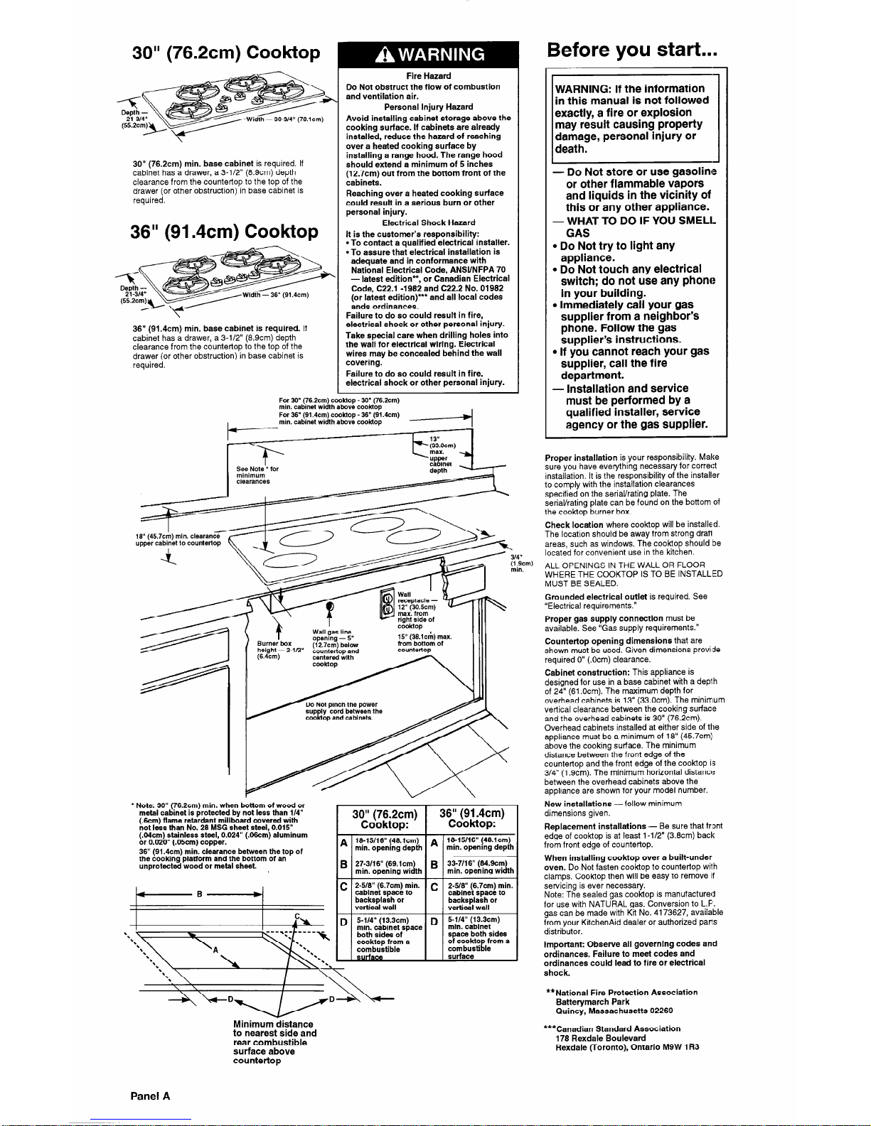
30” (76.2cm) Cooktop
Width - 30-3/4”
(76.lcm)
30” (76.2cm) min. base cabinet is required. If
cabinet has a drawer, a 3-112” (8.9cm) depth
clearance from the countertop to the top of the
drawer (or other obstruction) in base cabinet is
required.
36” (91.4cm) Cook-top
Width - 36” (91.4cm)
36” (91.4cm) min. base cabinet is required. If
cabinet has a drawer, a 3-l/2” (8.9cm) depth
clearance from the countertop to the top of the
drawer
(or other obstruction) in base cabinet is
required.
Fire Hazard
Do Not obstruct the flow of combustion
and ventilation air.
Personal Injury Hazard
Avoid installing cabinet storage above the
cooking surface. If cabinets are already
installed, reduce the hazard of reaching
over a heated cooking surface by
installing a range hood. The range hood
should extend a minimum of 5 inches
(12.7cm) out from the bottom front of the
cabinets.
Reaching over a heated cooking surface
could result in a serious burn or other
personal injury.
Electrical Shock Hazard
It is the customer’s responsibility:
l
To contact a qualified electrical installer.
l
To assure that electrical installation is
adequate and in conformance with
National Electrical Code, ANSVNFPA 70
- latest edition”,
or Canadian Electrical
Code, C22.1 -1982 and C22.2 No. 01982
(or latest edition) ** and all local codes
ands ordinances.
Failure to do so could result in fire,
electrical shock or other personal injury.
Take special care when drilling holes into
the wall for electrical wiring. Electrical
wires may be concealed behind the wall
covering.
Failure to do so could result in fire,
electrical shock or other personal injury.
I
For 30” (76.2cm) cooktop - 30’ (76.2cm)
min. cabinet width above cooktop
For 36” (91.4cm) cooktop - 36” (91.4cm)
min. cabinet width above cooktop
Y
::3.0cm)
max. a
up.pr
I
See Note” for
minimum
clearances
(12.7cm) below
countertop and
15” (36.lcr;l) max.
from bottom of
countertop
I”rr., --.- “.,...“_.. . ..-
cooktop and cabinets.
l
Note: 30” (76.2cm)
min. when bottom of wood or
metal cabinet is protected by not less than
l/4”
(km)
flame retardant millboard covered with
not less than No. 28 MSG sheet steel, 0.015”
(.04cm) stainless steel, 0.024” (.06cm) aluminum
or 0.020” (.05cm) copper.
36” (91.4cm) min. clearance between the top of
the cooking platform and the bottom of an
unprotected wood or metal sheet.
\‘:-----’
mm.
18-X/16” (48.lcm)
min. openmg depth
27-3/l 6” (69.1 cm)
min. opening width
2-5/S” (6.7cm) min.
cabinet space to
backsplash or
vertical wall
5-114” (13.3cm)
min. cabinet space
both sides of
cooktop from a
combustible
surface
l&15/16” (48.lcm)
min. openmg depth
33-7/16” (84.9cm)
min. opening width
2-5/8” (6.7cm) min.
cabinet space to
backsplash or
vertical wall
5-l/4” (13.3cm)
min. cabinet
space both sides
of cooktop from a
combustible
surface
Before you start...
WARNING: If the information
in this manual is not followed
exactly, a fire or explosion
may result causing property
damage, personal injury or
death.
1
- Do Not store or use gasoline
or other flammable vapors
and liquids in the vicinity of
this or any other appliance.
- WHAT TO DO IF YOU SMELL
GAS
l
Do Not try to light any
appliance.
l
Do Not touch any electrical
switch; do not use any phone
in your building.
l
Immediately call your gas
supplier from a neighbor’s
phone. Follow the gas
supplier’s instructions.
l
If you cannot reach your gas
supplier, call the fire
department.
- Installation and service
must be performed by a
qualified installer, service
agency or the gas supplier.
-
Proper installation is your responsibility. Make
sure you have everything necessary for correct
installation. It is the responsibility of the installer
to comply with the installation clearances
specified on the serial/rating plate. The
serial/rating plate can be found on the bottom of
the cooktop burner box.
Check location where cooktop will be installed.
The location should be away from strong drafi
areas, such as windows. The cooktop should be
located for convenient use in the kitchen.
ALL OPENINGS IN THE WALL OR FLOOR
WHERE THE COOKTOP IS TO BE INSTALLED
MUST BE SEALED.
Grounded electrical outlet is required. See
“Electrical requirements.”
Proper gas supply connection must be
available. See “Gas supply requirements.”
Countertop opening dimensions that are
shown must be used. Given dimensions provisde
required 0” (.Ocm) clearance.
Cabinet construction: This appliance is
designed for use in a base cabinet with a depi h
of 24” (61 .Ocm). The maximum depth for
overhead cabinets is 13” (33.0cm). The minirnum
vertical clearance between the cooking surface
and the overhead cabinets is 30” (76.2cm).
Overhead cabinets installed at either side of the
appliance must be a minimum of 18” (457cm)
above the cooking surface. The minimum
distance between the front edge of the
countertop and the front edge of the cooktop is
3/4” (1.9cm). The minimum horizontal distance
between the overhead cabinets above the
appliance are shown for your model number.
New installations -follow minimum
dimensions given.
Replacement installations - Be sure that fr’ont
edge of cooktop is at least 1 -l/2” (3.8cm) back
from front edge of countertop.
When installing cooktop over a built-under
oven. Do Not fasten cook-top to countertop with
clamps. Cooktop then will be easy to remove if
servicing is ever necessary.
Note: The sealed gas cooktop is manufactured
for use with NATURAL gas. Conversion to L.F’.
gas can be made with Kit No. 4173627, available
from your KitchenAid dealer or authorized pan:s
distributor.
Important: Observe all governing codes and
ordinances. Failure to meet codes and
ordinances could lead to fire or electrical
shock.
**National Fire Protection Association
Batterymarch Park
Quincy, Massachusetts 02269
***Canadian Standard Association
178 Rexdale Boulevard
Rexdale (Toronto), Ontario M9W 1 R3
Minimum distance
to nearest side and
rear combustible
surface above
countertop
Panel A

Tools needed for
installation:
-
Gas supply
requirements
Observe all governing codes and
ordinances.
Fire Hazard
l
Cooktop must be connected to a
regulated gas supply.
l
Do Not use an open flame to test for
leaks from gas connections.
l
New, CGAIA.G.A. design-approved,
flexible gas line should be used when
codes permit.
Failure to follow these instructions could
result in a fire, explosion or personal
injury.
A
n
This installation instruction must
conform with local codes and ordinances. In the
absence of local codes, installations must
conform with CANI - B149.1 or 2.
B
n
Input ratings shown on the serial/ratina
plate are to; elevations up to 2,000 feet (610m).For elevations above 2,000 feet (61 Om), ratings
are reduced at a rate of 4% for each 1,000 feet
(305m) above sea level. (For the USA only.)
C
n
This cooktop is equipped for use with
NATURAL gas. The serial/rating plate, located
on the bottom of the cooktop, has information on
the type of gas that can be used. If this
information does not agree with the type of gas
available, see your KitchenAid dealer or
authorized parts distributor.
D
n
Provide a gas supply line of 314”
(1.9cm) rigid pipe to the &&top location. A
smaller size pipe on long runs may result in
insufficient gas supply. Pipe-joint compounds,
made for use with NATURAL and L.P. gas, must
be used.
E
n
If local codes and ordinances permit,
CGA/A.G.A. design-certified, flexible metal
tubing is recommended for connecting this
cooktop to the gas supply line. Do Not kink or
damage the flexible tubing when moving the
cooktop. A 3/8” (.95cm) male pipe thread is
needed for connection to pressure regular
female pipe threads.
shutoff valve
F
n
The supply line shall be equipped with an
approved shutoff valve. This valve should be
located in the same room as the cooktop and
should be in a location that allows ease of
opening and closing. Do Not block access to
shutoff valve. The valve is for turning on or
shutting off gas to the appliance.
G
n
If rigid pipe is used as a gas
supply line, a combination of pipe fittings must
be used to obtain an in-line connection to the
cooktop. All strains must be removed from the
supply and fuel lines so cooktop will be level and
in line.
H
n
The regulator must be checked at a
minimum 1 -inch (2.5 cm) water column above
the set pressure. The inlet pressure to the
regular should be as follows for operation:
NATURAL GAS:
Set pressure 4 inches (10.2 cm)
Supply pressure 7 to 14 inches (17.8 cm to
35.5 cm) maximum
I
n
Line Pressure Testing:
Testing above 112 psi (3.5kPa) (gauge)
The cooktop and its individual shutoff valve must
be disconnected from the gas supply piping
system during any pressure testing of that
system at test pressures greater than l/2 psi (3.5
kPa).
Testing at l/2 psi (3.5kPa) (gauge) or lower
The cook-top must be isolated from the gas
supply piping system by closing its individual
manual shutoff valve during any pressure testing
of the gas supply piping system at test pressures
equal to or less than l/2 isi (3.5 kPa).
Electrical
requirements
Electrical Shock Hazard
l
Electrical ground is required on this
product.
l
Check with a qualified electrician if you
are in doubt as to whether the appliance
is properly grounded. Do Not modify the
plug on the power supply cord. tf it will
not fit the outlet, have a proper outlet
installed by a qualified electrician.
Improper connection of the equipmentgrounding conductor can result in a fire,
electrical shock or other personal injury.
l
Do Not use an extension cord with this
appliance.
Such use may result in a fire, electrical
shock or other personal injury.
A 120~volt, 60-Hz, AC-only, 15-or 20-ampere,
fused electrical supply is required. A time-delay
fuse or circuit breaker is recommended. It is
recommended that a separate circuit serving
only this appliance be provided.
Electronic ignition systems operate within wide
voltage limits, but proper grounding and
polarity is necessary for proper operation. In
addition to checking that the outlet provides 120volt power and is correctly grounded, the outlet
must be checked by a qualified electrician to see
if it is wired with correct polarity. A wiring
diagram is provided on the back cover.
This appliance, when installed, must be
electrically grounded in accordance with local
codes or, in the absence of local codes, with the
current CSA standard C22.1. Canadian Electrical
Code Part 1.
Recommended grounding method
For your personal safety, this appliance must
be grounded. This appliance is equipped with
a 3-prong grounding plug. To minimize possible
shock hazard, the cord must be plugged into a
mating 3-prong grounding-type wall receptacle,
grounded in accordance with the Canadian
Electrical Code (CSA) - latest edition and local
codes and ordinances. See Figure 1.
If a mating wall receptacle is not available, it is
the personal responsibility and obligation of the
customer to have a properly grounded, 3-prong
wall receptacle installed by a qualified
electrician.
3-prong
supply cord
Figure 1
Now start...
With cooktop in kitchen.
Property Damage
Lift entire cooktop up from cutout when
repositioning cooktop in countertop
opening.
Failure to do so could scratch countertop.
11.1
Remove shipping materials and tape
from cooktop. Remove pressure
regulator and hardware package from
side of carton.
Remove cooktop, burner grates and
caps package from shipping box.
cl
3
Remove the paper backing from a
small section of the foam sealing strip.
n
Place the strip l/8” (0.3cm) from
cooktop edge on the underside of the
glass. Continue until foam strip completely
outlines the edge of the cooktop. Do Not use
additional sealant around outer edge of cooktop.
Panel B
 Loading...