

LP GAS AND HIGH ALTITUDE CONVERSION
INSTRUCTIONS
For KFGU and KFGS Model Series
INSTRUCTIONS DE CONVERSION - GAZ PROPANE
ET ALTITUDE ÉLEVÉE
Pour séries de modèles KFGU et KFGS
Table of Contents/Table des matières
COOKTOP SAFETY........................................................................1
Tools and Parts ............................................................................2
Convert from Natural Gas to LP Gas...........................................3
Convert from LP Gas to Natural Gas...........................................5
Lighting the Electronic Igniters ....................................................7
Flame Height Adjustment.............................................................7
Complete Burner Adjustment ......................................................8
COOKTOP SAFETY
SÉCURITÉ DE LA TABLE DE CUISSON ......................................9
OUTILLAGE ET PIÈCES...............................................................10
Conversion de Gaz naturel à Propane.......................................11
Conversion de Propane à Gaz naturel.......................................13
Allumeurs électroniques - allumage...........................................15
Réglage de la taille des flammes ...............................................15
Achever le réglage des brûleurs.................................................16
Your safety and the safety of others are very important.
We have provided many important safety messages in this manual and on your appliance. Always read and obey all safety
messages.
This is the safety alert symbol.
This symbol alerts you to potential hazards that can kill or hurt you and others.
All safety messages will follow the safety alert symbol and either the word “DANGER” or “WARNING.”
These words mean:
You can be killed or seriously injured if you don't immediately
DANGER
WARNING
All safety messages will tell you what the potential hazard is, tell you how to reduce the chance of injury, and tell you what can
happen if the instructions are not followed.
IMPORTANT:
Installer: Leave installation instructions with the homeowner.
Homeowner: Keep installation instructions for future reference.
IMPORTANT :
Installateur : Remettre les instructions d'installation au propriétaire.
Propriétaire : Conserver les instructions d'installation pour référence ultérieure.
follow instructions.
can be killed or seriously injured if you don't
You
instructions.
follow
W10411931A
WARNING: If the information in this manual is not followed exactly, a fire or explosion
may result causing property damage, personal injury or death.
– Do not store or use gasoline or other flammable vapors and liquids in the vicinity of this
or any other appliance.
– WHAT TO DO IF YOU SMELL GAS:
Do not try to light any appliance.
•
Do not touch any electrical switch.
•
Do not use any phone in your building.
•
Immediately call your gas supplier from a neighbor's phone. Follow the gas supplier's
•
instructions.
If you cannot reach your gas supplier, call the fire department.
•
– Installation and service must be performed by a qualified installer, service agency or
the gas supplier.
WARNING: Gas leaks cannot always be detected by smell.
Gas suppliers recommend that you use a gas detector approved by UL or CSA.
For more information, contact your gas supplier.
If a gas leak is detected, follow the “What to do if you smell gas” instructions.
In the State of Massachusetts, the following installation instructions apply:
■ Installations and repairs must be performed by a qualified or licensed contractor, plumber, or gasfitter qualified or licensed by
the State of Massachusetts.
■ If using a ball valve, it shall be a T-handle type.
■ A flexible gas connector, when used, must not exceed 3 feet.
Tools and Parts
Gather the required tools and parts necessary for correct LP gas
conversion.
Too ls nee de d
■ Flat-blade screwdriver
■ ³⁄₃₂" (#0 [2.0 mm]) flat-blade screwdriver (screwdriver shaft
must be a minimum of 2" [5.1 cm] long)
■ Adjustable wrench
■ 7.0 mm nut driver
■ 7.0 mm wrench
Parts supplied
■ LP orifice package (W10418070)
■ Conversion instructions (W10411931A)
■ Conversion label (W10418075)
High Altitude Conversion
To convert the cooktop for elevations above 6,560 ft (1999.5 m),
order a High Altitude Conversion Kit.
■ Part Number W10418078 - LP high altitude
■ Part Number W10418080 - Natural gas high altitude
To order, see the “Assistance or Service” section of the Use and
Care Guide.
2
IMPORTANT: Gas conversions from Natural gas to LP gas must
C
B
be done by a qualified installer. Before proceeding with
conversion, shut off the gas supply to the cooktop prior to
disconnecting the electrical power.
Convert from Natural Gas to LP Gas
1. Turn manual shutoff valve to the closed position.
2. Unplug cooktop or disconnect power.
WARNING
This conversion kit shall be installed by a
qualified service agency in accordance
with the manufacturer's instructions and
all applicable codes and requirements of
the authority having jurisdiction. If the
information in these instructions is not
followed exactly, a fire, explosion or
production of carbon monoxide may
result causing property damage, personal
injury or loss of life. The qualified service
agency is responsible for the proper
installation of this kit. The installation is
not proper and complete until the
operation of the converted appliance is
checked as specified in the
manufacturer's instructions supplied with
this kit.
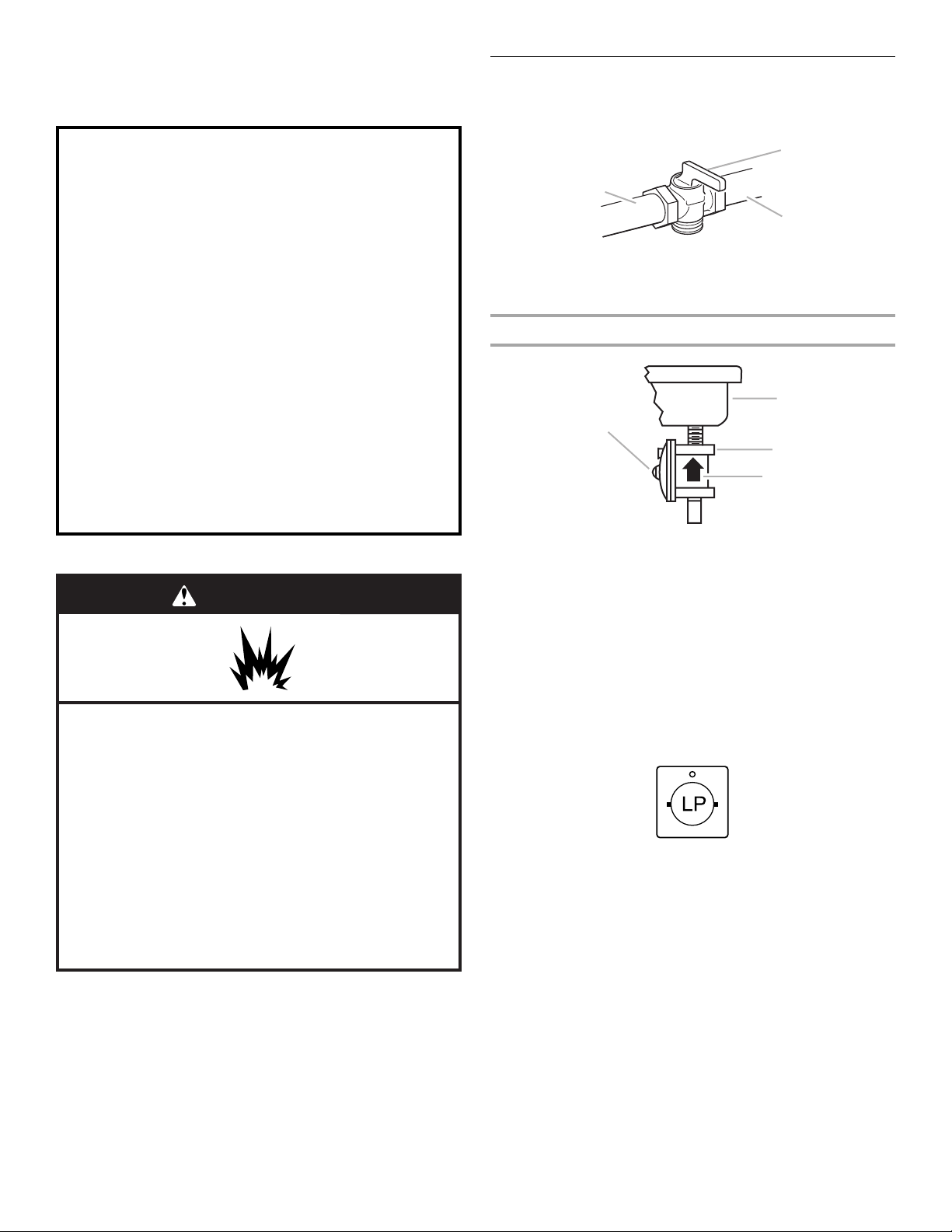
WARNING
Explosion Hazard
Use a new CSA International approved gas supply line.
Install a shut-off valve.
Securely tighten all gas connections.
If connected to LP, have a qualified person make sure
gas pressure does not exceed 14" (36 cm) water
column.
Examples of a qualified person include:
licensed heating personnel,
authorized gas company personnel, and
authorized service personnel.
Failure to do so can result in death, explosion, or fire.
B
A
A. To cooktop
B. Shutoff valve (closed position)
C. Gas supply line
To Convert Gas Pressure Regulator
A
C
D
A. Access cap
B. Rear of cooktop
C. Gas pressure regulator
D. Gas flow
3. Determine the type of regulator you have:
Style 1: The cap has a slot and “NAT” printed on it.
Remove access cap by using a flat-blade screwdriver or coin,
turning the access cap counterclockwise.
The gas pressure regulator has 2 settings that are stamped
on either side of the cap. Turn the cap and reinstall into
regulator with the stamp “LP” visible from the outside of the
regulator.
Style 2: The cap does not have a slot and requires a wrench
to be removed.
Remove the access cap by using a wrench, turning the
access cap counterclockwise.
Remove spring retainer from the cap by pushing against the
flat side of the spring retainer. Look at the spring retainer to
locate the “NAT” or “LP” position. Turn over the spring
retainer so the “LP” is showing on the bottom. Snap the
spring retainer back into the cap. Reinstall the cap onto the
regulator.
3
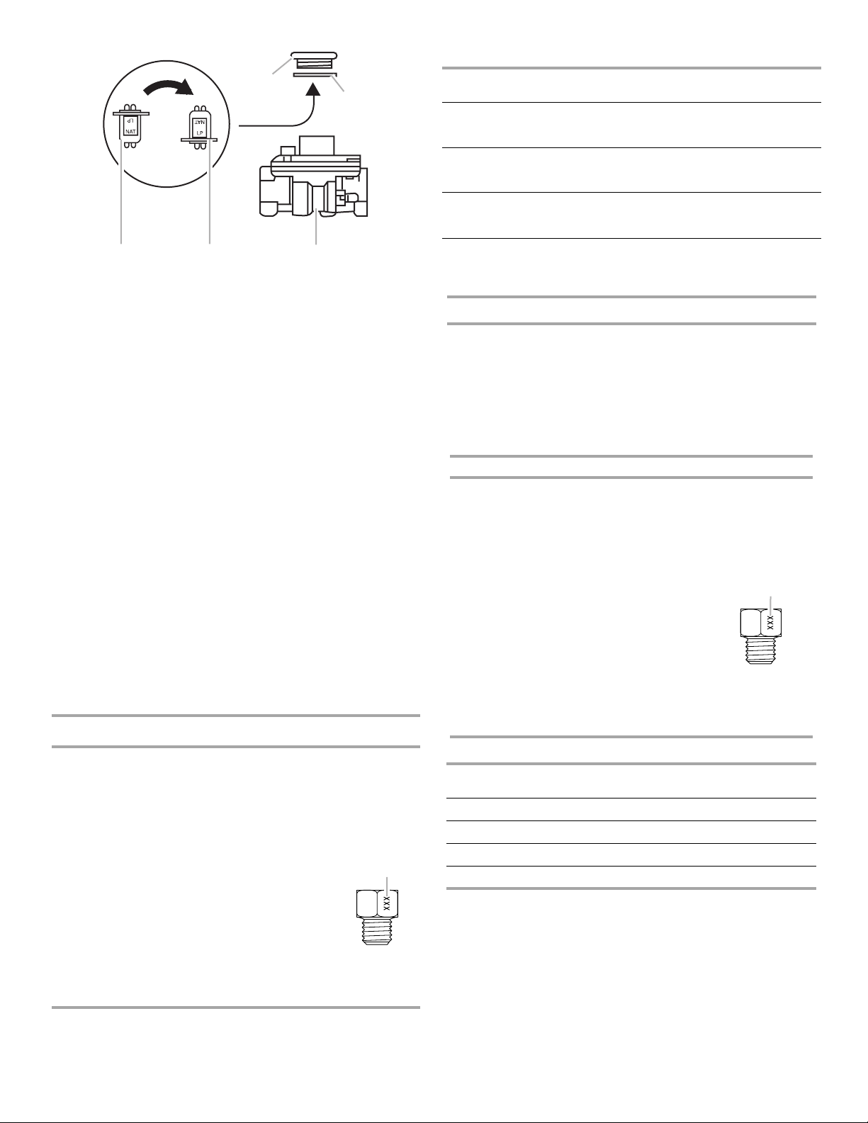
A
B
CDE
A. Access cap
B. Gasket
C. Gas pressure regulator
D. LP position
E. NAT position
4. Test the gas pressure regulator and gas supply line.
The regulator must be checked at a minimum 1" (2.5 cm)
water column above the set pressure. The inlet pressure to
the regulator should be as follows for operation and checking
the regulator setting:
LP Gas:
Minimum pressure 10" (25.4 cm) W.C.P.
Supply pressure 14" (35.5 cm) W.C.P.
Gas Supply Pressure Testing
Line pressure testing above ½ psi gauge (14" WCP)
The cooktop and its individual shutoff valve must be
disconnected from the gas supply piping system during any
pressure testing of that system at test pressures in excess of
½ psi (3.5 kPa).
Line pressure testing at ½ psi gauge (14" WCP) or lower
The cooktop must be isolated from the gas supply piping
system by closing its individual manual shutoff valve during
any pressure testing of the gas supply piping system at test
pressures equal to or less than ½ psi (3.5 kPa).
5. If installed, remove the burner grates.
Use the following charts to match the correct gas orifice spud
with the burner location and model being converted.
LP Gas Orifice Spud Chart
Burner
Rating
5,000 BTU White
6,000 BTU Green 074 0.74 mm
8,000 BTU Yellow 083 0.83 mm
9,100 BTU Black 089 0.89 mm
11,000 BTU Orange 097 0.97 mm
12,000 BTU
Outer
Inner
14,000 BTU
Outer
Inner
16,000 BTU
Outer
Inner
Color Stamp
(no color)
No color
No color
No color
No color
No color
No color
(A)
066 0.66 mm
094
45
101
45
110
45
Size
0.94 mm
0.45 mm
1.01 mm
0.45 mm
1.10 mm
0.45 mm
A
A. Size stamp
Burner Models
Model
No.
KFGS306 089
KFGS366 089
KFGU706 097
KFGU766 089
Right
front
Black
Black
Orange
Black
Right
rear
074
Green
074
Green
074
Green
074
Green
Center
(outer)
094
No color45No color
101
No color45No color
094
No color45No color
110
No color45No color
Center
(inner)
Left
front
083
Yellow
089
Black
083
Yellow
097
Orange
Left rear
066
White
(no color)
066
White
(no color)
066
White
(no color)
066
White
(no color)
High Altitude Conversions
IMPORTANT: You must convert LP gas with LP gas high altitude
kit Part Number W10418078 or Natural gas with Natural gas high
altitude kit Part Number W10418080. If you need to convert LP
gas to Natural gas high altitude or Natural gas to LP gas high
altitude, you must convert the pressure regulator. For this you
must follow steps 1, 2 and 3 of the respective conversion that
you need.
LP Gas Orifice Spud Chart for High Altitude Conversion
Burner Rating Stamp (A) Size
5,000 BTU 062 0.62 mm
6,000 BTU 070 0.70 mm
8,000 BTU 079 0.79 mm
9,100 BTU 085 0.85 mm
11,000 BTU 092 0.92 mm
12,000 BTU
Outer
Inner
14,000 BTU
Outer
Inner
16,000 BTU
Outer
Inner
089
45
097
45
101
45
0.89 mm
0.45 mm
0.97 mm
0.45 mm
1.01 mm
0.45 mm
A. Size stamp
Burner Models
Model
No.
KFGS306 085 070 089 45 079 062
KFGS366 085 070 097 45 085 062
KFGU706 092 070 089 45 079 062
KFGU766 085 070 101 45 092 062
Right
front
Right
rear
Center
(outer)
Center
(inner)
Left
front
A
Left
rear
4
Burner locations
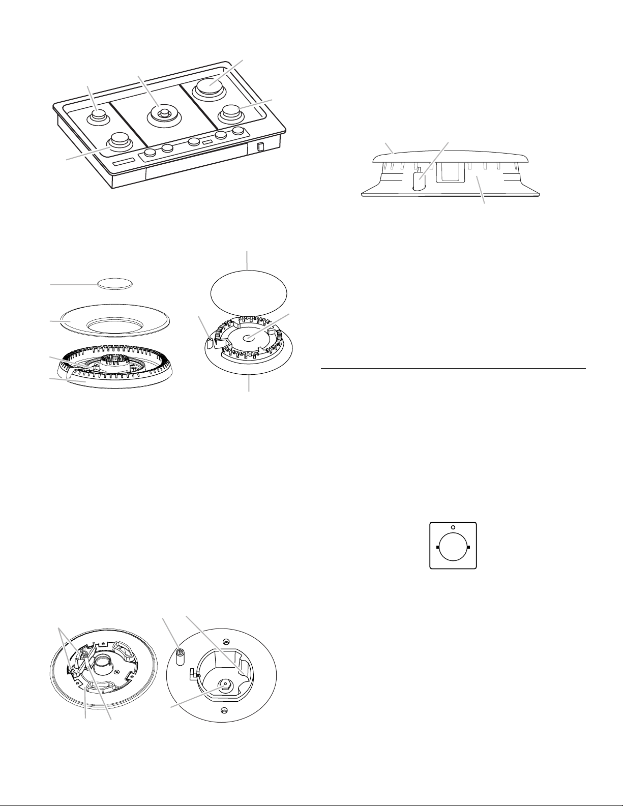
D
B
9. Place Natural gas orifice spuds in plastic parts bag for future
D
C
use and keep with package containing literature.
10. Replace sheet of insulation.
11. Replace burner bases and burner caps.
IMPORTANT: The igniter electrode is ceramic and could
E
break during conversion. Be sure that the electrode comes
through the hole in the burner smoothly while replacing the
burner base.
A
A. Left front
B. Left rear
C. Center
D. Right rear
E. Right front
6. Remove all burner caps and burner bases.
A
A
B
B
C
D
C
Center Burner
A. Inner burner cap
B. Outer burner cap
C. Gas tube opening
D. Burner base
Standard Burner
A. Burner cap
B. Igniter electrode
C. Burner base
D. Gas tube opening
7. To Convert Right or Left Burners:
■ Insert 7.0 mm nut driver down onto the gas orifice spud
(C) and remove by turning it counterclockwise and lifting
out.
■ Set gas orifice spud aside.
■ Replace with correct LP gas orifice spud. See the LP Gas
Orifice Spud Charts.
8. To Convert Center Burners:
■ Use 7.0 mm wrench to loosen and remove the orifice
spud (C).
■ Replace with correct LP gas orifice spud. See the LP Gas
Orifice Spud Charts.
B
A
C
A
B
C
A. Burner cap
B. Electrode
C. Burner base
12. Open shutoff valve in the gas supply line. The valve is open
when the handle is parallel to the gas pipe.
13. Plug in cooktop or reconnect power.
REMEMBER: Once you have completed converting all of the
cooktop burners, test the cooktop for leaks by brushing on
an approved noncorrosive leak-detection solution. If bubbles
appear, a leak is indicated. Correct any leaks found.
14. Adjust single and dual valve according to “Flame Height
Adjustment” section.
Convert from LP Gas to Natural Gas
1. Turn manual shutoff valve to the closed position.
2. Unplug cooktop or disconnect power.
3. Determine the type of regulator you have:
Style 1: The cap has a slot and “LP” printed on it.
Remove access cap by using a flat-blade screwdriver or coin,
turning the access cap counterclockwise.
The gas pressure regulator has 2 settings which are stamped
on either side of the cap. Turn the cap and reinstall into
regulator with the stamp “NAT” visible from the outside of the
regulator.
NAT
Style 2: The cap does not have a slot and requires a wrench
to be removed.
Remove the access cap by using a wrench, turning the
access cap counterclockwise.
Remove spring retainer from the cap by pushing against the
flat side of the spring retainer. Look at the spring retainer to
locate the “LP” or “NAT” position. Turn over the spring
retainer so the “NAT” is showing on the bottom. Snap the
spring retainer back into the cap. Reinstall the cap onto the
regulator.
C
A
B
A. Igniter electrode
B. Orifice holder
C. Orifice spud
5
 Loading...