

KitchenAid KFGR274, KFGR364, KBGN292 Installation Instructions
Part No.8285350 Rev. A
Installation Instructions and
Use and Care Guide
IMPORTANT:
Installer: Leave Installation Instructions with the consumer.
Consumer: Keep Installation Instructions for future reference.
Save Installation Instructions for local electrical inspector’s use.
Write the model and serial numbers in space provided below before
installing or using outdoor grill.The numbers are stamped on the
identification label located on the underside of grill drip tray. It is also
located on the model/serial number plate, located on heat shield
behind control panel close to the smoker box.
Model # __________________________
Serial #___________________________
IMPORTANT:
Read and save these instructions.
For the way it’s made
®
®
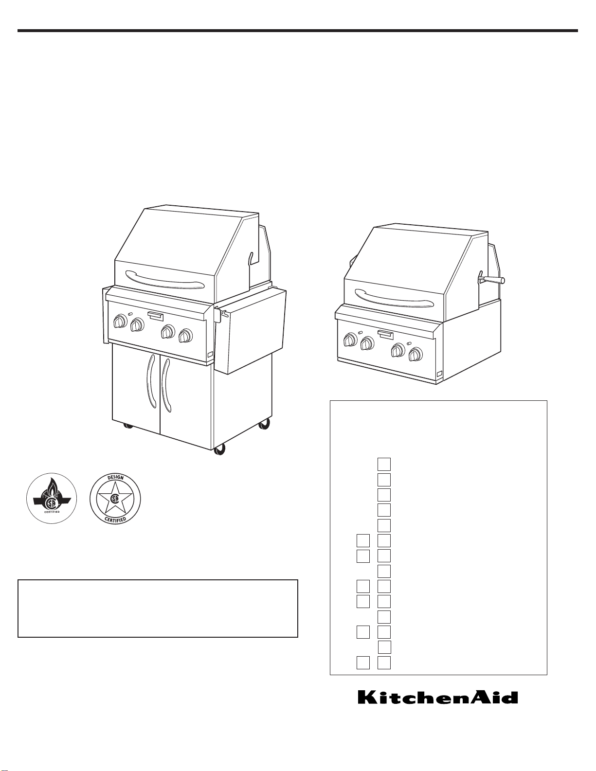
27" (68.6 cm), 36" (91.4 cm), 39" (99.1 cm) and
48" (121.9 cm) Outdoor Grills
(Portable and Built-in — non-combustible construction)
Quick Reference
Table of Contents:
Pages
Before you start
Product dimensions
Built-In installation dimensions
Gas supply requirements
Rotisserie electrical requirements
Installation steps – Portable models
Installation steps – Built-In models
Checking/adjusting burners
Use and Care Information
Grilling tips & chart
Rotisserie tips & chart
Cleaning
Warranty
Requesting Assistance or Service
2
4
4
5
6
7- 8
9 - 10
11
12 - 14
14 - 16
17
18 - 19
20
21 - 22
27" (68.6 cm)
Portable without
rotisserie shown
Models
KFGR270
KFGR274
KFGR292
KFGR364
KFGR382
Models
KBGN274
KBGN364
KBGN292
27" (68.6 cm)
Built-In with
rotisserie shown
1. Do not install por table or built-in grills
in or on a recreational vehicle,
portable trailer, boat or in any other
moving installation.
2. Always maintain minimum clearances
from combustible construction, see
“Location requirements” section.
3.The outdoor cooking gas appliance
shall not be located under overhead
combustible construction.
4.This outdoor cooking gas appliance
shall be used only outdoors and shall
not be used in a building, garage, or
any other enclosed area.
5. Keep any electrical supply cord and
fuel supply hose away from any
heated surfaces.
6. Keep outdoor cooking and appliance
area clear and free from combustible
materials, gasoline and other
flammable vapors and liquids.
7. Do not obstruct the flow of combustion
and ventilation air. Keep the ventilation
openings of the cylinder enclosure free
and clear from debris.
8. Inspect the gas cylinder supply hose
before each use of the grill. If the
hose shows excessive abrasion or
wear, or is cut, it MUST be replaced
before using the grill. Contact your
dealer and use only replacement
hoses specified for use with the grill.
9.Visually check the burner flames.
They should be blue.Slight yellow
tipping is normal for L.P. gas.
10. Check and clean burner/venturi tube
for insects and insect nest.A clogged
tube can lead to fire under the grill.
11.The L.P. gas supply cylinder to be
used must be:
• constructed and marked in
accordance with the Specification
for L.P. Gas Cylinders of the U.S.
Department of Transportation (DOT)
or the National Standard of Canada,
CAN/CSA-B339, Cylinders, Spheres,
and Tubes for Transportation of
Dangerous Goods; and Commission.
• provided with a listed overfilling
prevention device.
• provided with a cylinder connection
device compatible with the connection for outdoor grill appliances.
12. Always check connections for leaks
each time you connect and
disconnect the L.P. gas supply
cylinder.See “Installation
Instructions” section.
13.When the outdoor cooking gas
appliance is not in use, the gas must
be turned off at the supply cylinder.
14. Storage of an outdoor gas grill
appliance indoors is permissible only
if the cylinder is disconnected and
removed from the outdoor gas grill.
15. Cylinders must be stored outdoors
and out of the reach of children and
must not be stored in a building,
garage, or any other enclosed area.
16.The pressure regulator and hose
assembly supplied with the outdoor
gas grill must be used. Replacement
pressure regulator and hose
assembly part number listed in
the “Installation Instructions” section.
17.The cylinder supply system must be
arranged for proper vapor
withdrawal.
18. Gas cylinder must include a collar to
protect the cylinder valve.
Before you start...
You can be killed or seriously
injured if you don’t follow
instructions.
DANGER
Your safety and the safety of
others are very important.
We have provided many important
safety messages in this manual and
on your appliance.Always read and
obey all safety messages.
All safety messages will tell you what
the potential hazard is, tell you how to
reduce the chance of injury, and tell
you what can happen if the
instructions are not followed.
You can be killed or seriously
injured if you don’t immediatel
y
follow instructions.
WARNING
For grills that are to be used at
elevations above 2000 feet, orifice
conversion is required. See “Gas
supply requirements” section.
It is the responsibility of the installer to
comply with the minimum installation
clearances specified on the model/serial
rating plate.The model/ser ial rating plate
can be found on the heat shield behind
control panel, close to smoker box.
WARNING: If the information
in this manual is not followed
exactly, a fire causing death
or serious injury may occur.
2
Copies of the standards listed may be obtained
from:
National Fire Protection Association
One Batterymarch Park
Quincy, Massachusetts 02269
CSA International
8501 East Pleasant Valley Rd.
Cleveland, Ohio 44131-5575
This is the safety alert symbol.
This symbol alerts you to
potential hazards that can kill
or hurt you and others.
All safety messages will follow the
safety alert symbol and either the word
“DANGER” or “WARNING”.These
words mean:
FOR YOUR SAFETY
If you smell gas:
1. Shut off gas to the
appliance.
2. Extinguish any open flame.
3. Open lid.
4. If odor continues,
immediately call your gas
supplier or your fire
department.
FOR YOUR SAFETY
1. Do not store or use
gasoline or other
flammable vapors and
liquids in the vicinity of
this or any other appliance.
2. An L.P. cylinder not
connected for use shall not
be stored in the vicinity of
this or any other appliance.
IMPORTANT:
This grill is manufactured for
outdoor use only.
IMPORTANT SAFETY INSTRUCTIONS
If the following information is not
followed exactly, a fire causing death or
serious injury may occur.
• Do not store a spare LP-gas cylinder
under or near this grill.
• Never fill the cylinder beyond 80
percent full.
3
Tools and parts
needed for Built-in
(non-combustible
construction)
installations
Location requirements
Parts supplied
• convertible regulator is set for 4" W.C.
natural gas.
Parts needed
The portable grills are manufactured
for use with L.P./Propane gas.
To convert to Natural gas, Gas
Conversion Kit no. 4396312
must
be
used. Instructions included with kit.
• To connect to a fixed L.P./propane gas
supply, you must purchase Convertible
Regulator Kit No.4396424 from your
dealer.
Parts needed
The built-in grills are manufactured for
use with natural gas.
To convert to L.P./propane gas, Gas
Conversion Kit no. 4396311 must be
used. Follow Instructions included with kit.
• level
• small flat-blade screwdriver
• flat-blade screwdriver
• Phillips screwdriver
• tape measure or ruler
• slip-joint pliers
• pipe wrench
• scissors or cutting pliers to remove
tiedowns
Materials required:
• gas line shutoff valve
• 1/2" male pipe thread nipple for connection
to pressure regulator
• L.P. gas-resistant pipe-joint compound
• AGA or CSA design-certified outdoor
flexible stainless steel appliance connector
[4-5 ft. (1.2-1.5 m)] or rigid gas supply line
as needed
• non-corrosive leak detection solution
Tools and parts needed for Portable installations
Parts supplied
• hose and regulator assembly set for 11"
W.C. L.P. gas (attached to manifold)
• 20 lb.L.P. tank (empty) – requires purging
and L.P. gas fill by certified L.P. gas fill
station
• level
• small flat-blade screwdriver
• flat-blade screwdriver
• Phillips screwdriver
• tape measure or ruler
• slip-joint pliers
• adjustable wrench
• scissors or cutting pliers to remove
tiedowns
Materials required:
• non-corrosive leak detection solution
Select a location
that provides minimum
exposure to wind and traffic paths.The
location should be away from strong draft
areas.
Do not obstruct flow of combustion and
ventilation air.
If you plan to use a
combustible enclosure,
return this unit and replace it with the
model which is manufactured for use in a
combustible enclosure.
Clearance to combustible construction
for built-in (non-combustible
construction) and portable grills:
A minimum of 12" (30.5 cm) must be
maintained between the grill hood, sides
and back and any combustible construction.
A 12" (30.5 cm) minimum clearance must
also be maintained below the cooking
surface and any combustible construction.
Rotisserie
If your model is equipped with a
rotisserie, 6" (15.2 cm) minimum
clearance on each end is needed for the
motor and skewer.
A grounded, 3-prong outlet located to the
left of the grill is required. (See “Electrical
requirements” section.)
WARNING
Fire Hazard
Do not use grill near combustible
materials.
Do not store combustible materials
near grill.
Doing so can result in death or fire.
WARNING
Explosion Hazard
Do not store fuel tank in a garage or
indoors.
Do not store grill with fuel tank in a
garage or indoors.
Failure to follow these instructions
can result in death, explosion, or fire.
The California Safe Drinking Water and
Toxic Enforcement Act requires the
Governor of California to publish a list of
substances known to the State of
California to cause cancer, birth defects,
or other reproductive harm, and requires
businesses to warn of potential exposure
to such substances.
WARNING:This product contains a
chemical known to the State of California
to cause cancer, birth defects, or other
reproductive harm.
This appliance can cause low-level
exposure to some of the substances
listed, including benzene, crystalline silica,
carbon monoxide, toluene, and soot.
WARNING
Fire Hazard
Do not install this grill on or near
combustible materials.
Doing so can result in death or fire.
In the State of Massachusetts, the
following installation instructions apply:
• Installations and repairs must be
performed by a qualified or licensed
contractor, plumber, or gasfitter
qualified or licensed by the State of
Massachusetts.
• If using a ball valve, it shall be a
T-handle type.
• A flexible gas connector, when used,
must not exceed 3 feet.
4
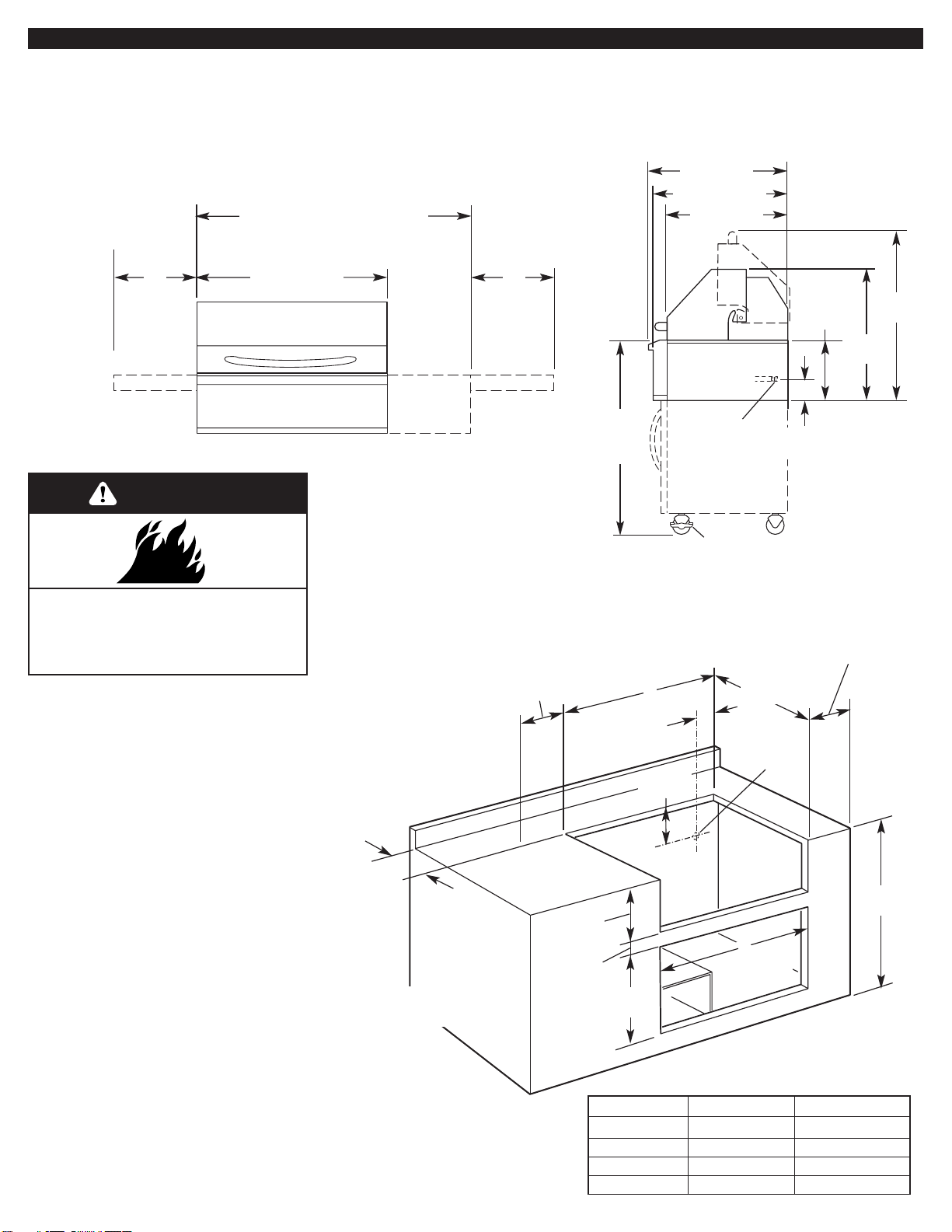
Product Dimensions
Built-in Installation
Dimensions
(non-combustible
enclosure)
36"
(91.4 cm)
portable
models
24-5/8"
(62.5 cm)
34"
(86.4 cm)
11-1/8"
(28.3 cm)
3-5/8"
(9.2 cm)
1/2"
male NPT
locking front
casters
side tray*
side burner*
side tray*
*Not all models have side burner or side trays.
23" (58.4 cm)
25-1/2" (64.8 cm)
26" (66.0 cm)
27" (68.6 cm), or
36" (91.4 cm)
39" (99.1 cm)
[27" (68.6 cm) grill with
12" (30.5 cm) side burner]
48" (121.9 cm)
[36" (91.4 cm) grill
with 12" (30.5 cm) side burner]
Portable and
Built-in models
IMPORTANT: If grill is to be installed in a
combustible enclosure, return this unit and replace it
with the model which is manufactured for use in a
combustible enclosure.
Enclosure and clearance dimensions
that are
shown must be used. Given dimensions provide
required clearances.
The installation of this grill must conform with the
current standards CSA-Z21.58a-1998*, or with
local codes.
For installations in a
non-combustible enclosure
,
the grill drops into the opening and is supported
by its side flanges. Do not use a bottom suppor t.
Copies of the standards listed may
be obtained from:
*CSA International
8501 East Pleasant Valley Rd.
Cleveland, Ohio 44131-5575
A
22"
(57.2 cm)
2-1/4"
(5.7 cm)
7-3/8"
(18.7 cm)
gas line
location at
rear of grill
6" (15.2 cm)
min. clearance
for rotisserie
12" (30.5 cm)
minimum to
any accessory
2" (5.1 cm)
minimum to
open hood
counter or support surfaces
must be level
10-7/8"
(27.0 cm)
19"
(48.3 cm)
35-1/2"
(90.2 cm)
1-1/8"
(2.9 cm)
Grill size A B
27" (68.6 cm) 26" (66.7 cm) 25-1/4" (64.1 cm)
36" (91.4 cm) 35" (89.5 cm) 34-1/4" (87.0 cm)
39" (99.1 cm) 38" (97.2 cm) 37-1/4" (94.6 cm)
48" (121.9 cm) 47" (119.4 cm) 46-1/4" (117.5 cm)
Non-combustible enclosure installations
12"
(30.5 cm)
12"
(30.5 cm)
Clearance to combustible construction for built-in (non-combustible construction) and portable grills:
A minimum of 12" (30.5 cm) must be maintained between the grill hood, sides and back and any combustible construction.
A 12" (30.5 cm) minimum clearance must also be maintained below the cooking surface and any combustible construction.
optional custom
access doors
B
WARNING
Fire Hazard
Do not install this grill on or near
combustible materials.
Doing so can result in death or fire.
5
Line pressure testing:
Testing above 1/2 psi (3.5 kPa) or
14 inches (35.5 cm) W.C. (gauge)
The grill and its individual shutoff valve
must be disconnected from the gas
supply piping system during any pressure
testing of that system at test pressures
greater than 1/2 psig (3.5 kPa).
Testing below 1/2 psi (3.5 kPa) or
14 inches (35.5 cm) W.C. (gauge) or
lower
The grill must be isolated from the gas
supply piping system by closing its
individual manual shutoff valve during any
pressure testing of the gas supply piping
system at test pressures equal to or less
than 1/2 psig (3.5 kPa).
Gas supply requirements
Observe all governing codes and
ordinances.
IMPORTANT: Grill must be connected
to a regulated gas supply.
• Input ratings shown on the model/serial
rating plate are for elevations up to 2,000
feet (610 m). For elevations above 2,000
feet (610 m), ratings are reduced at a
rate of 4% for each 1,000 feet (305 m)
above sea level. Or ifice conversion is
required. Contact KitchenAid Assistance
Center.
• Refer to the model/serial rating plate for
information on the type of gas that can
be used. If this information does not
agree with the type of gas available,
check with your local gas supplier.
No attempt shall be made to convert
the grill from the gas specified on the
model/serial rating plate for use with a
different gas type without consulting the
serving gas supplier.The conversion
kits specified must be used.
Portable Grills
L.P. Gas:
This grill is equipped for use with a L.P.
gas fuel tank. It is design-cer tified by CSA
International for local L.P. gas supply or
for Natural gas with appropriate
conversion.
L.P. gas from a local L.P. gas supply:
IMPORTANT:
The gas installation must
conform with local codes, or in the
absence of local codes, with the National
Fuel Gas Code, ANSI Z223.1/NFPA 54.
The qualified L.P. gas technician shall
provide the L.P. gas supply to the
selected grill location in accordance with
the National Fuel Gas Code, NFPA 54
and local codes.
Natural gas conversion:
Conversion must be made by a qualified
gas technician.
The qualified natural gas
technician shall provide the natural gas
supply to the selected grill location in
accordance with the National Fuel Gas
Code NFPA 54 and local codes. For
conversion to Natural gas, the Natural
gas conversion kit must be used.
IMPORTANT:
The gas installation must
conform with local codes, or in the
absence of local codes, with the National
Fuel Gas Code, ANSI Z223.1/NFPA 54.
To convert to Natural gas, the Natural
Gas Conversion Kit No. 4396312 must be
used, Instructions are included with the
kit.
L.P. GAS:
Operating pressure:
11 inches (27.9 cm) W.C.
Supply pressure: 11 to 14 inches
(27.9 to 35.5 cm) W.C.
NATURAL GAS:
Set pressure 4 inches (10.2 cm) W.C.
Supply pressure 7-14 inches
17.8 cm to 35.5 cm) W.C. maximum.
L.P. gas conversion from a local L.P. gas
supply:
Conversion must be made by a qualified
gas technician.
The qualified natural gas
technician shall provide the L.P. gas
supply to the selected grill location in
accordance with the National Fuel Gas
Code NFPA 54 and local codes.To
convert to L.P. gas, the L.P. Gas
Conversion Kit No. 4396311 must be
used. Follow Instructions included with kit.
L.P. gas conversion using a L.P. fuel tank:
To convert to L.P. gas, the L.P. Gas
Conversion Kit No. 4396311 must be
used. Follow Instructions included with kit.
A L.P. gas cylinder, not larger than 20
pounds, must be purchased separately.
NATURAL GAS:
Set pressure 4 inches (10.2 cm) W.C.
Supply pressure 7-14 inches
17.8 cm to 35.5 cm) W.C. maximum.
L.P. GAS:
Operating pressure:
11 inches (27.9 cm) W.C.
Supply pressure: 11 to 14 inches
(27.9 to 35.5 cm) W.C.
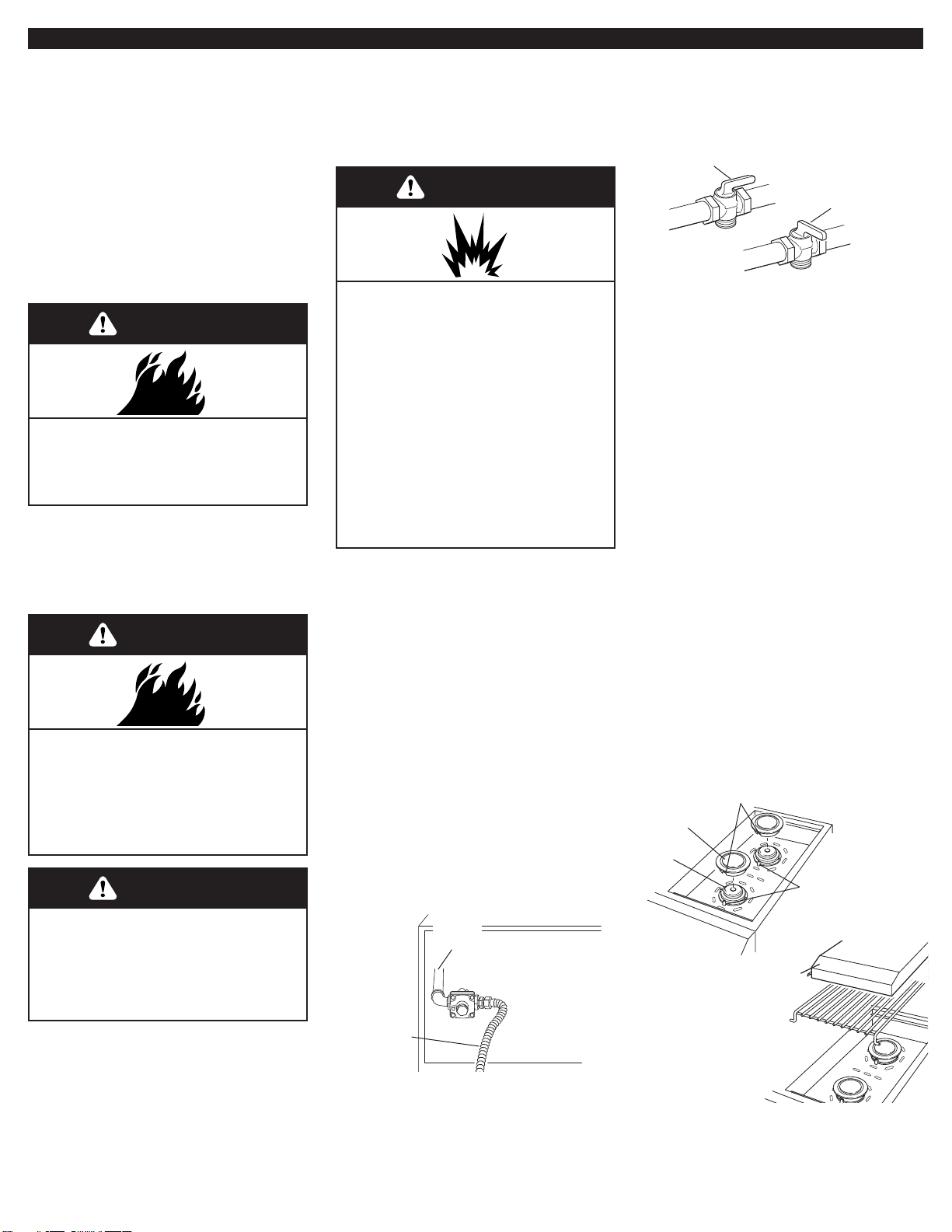
gas supply
line
shutoff valve
“open” position
to grill
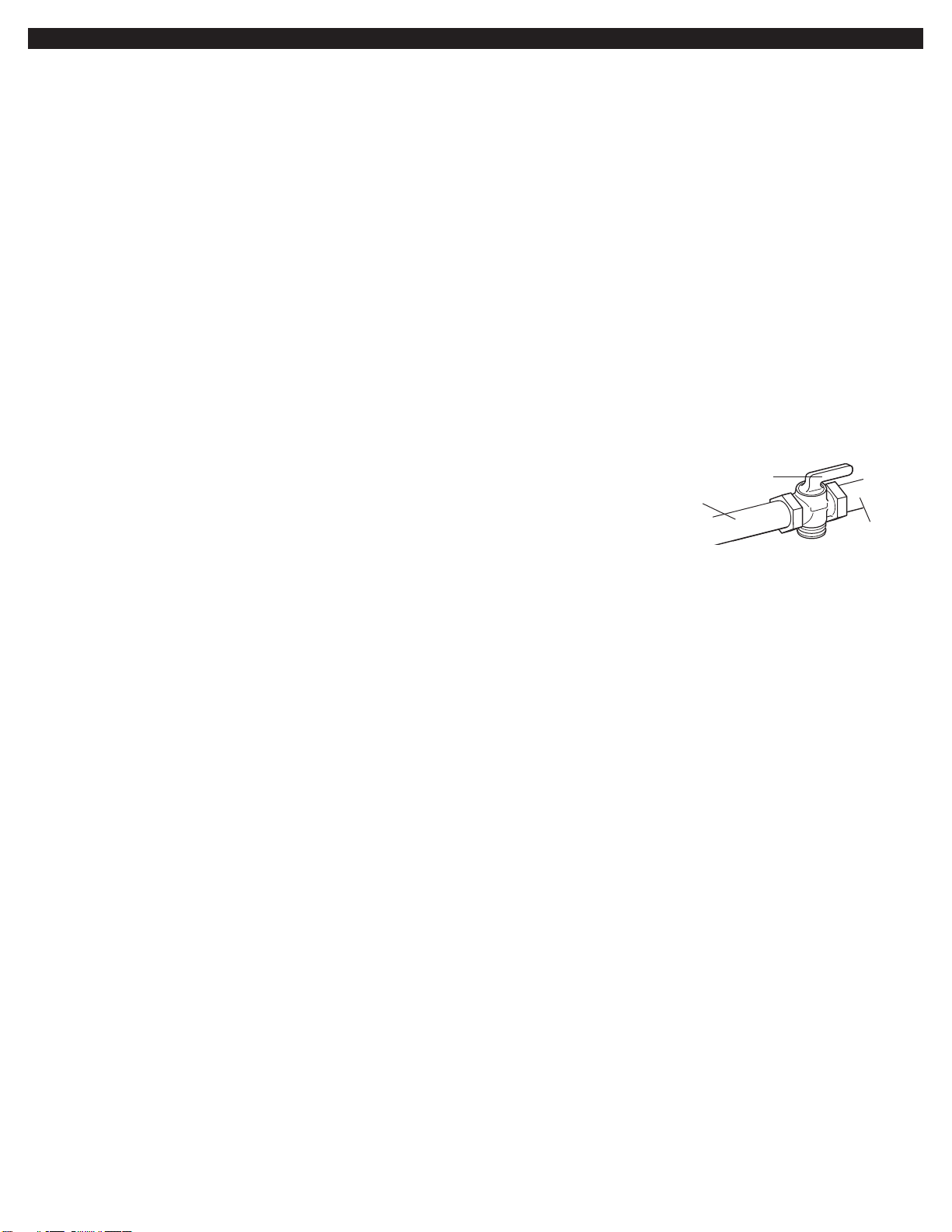
The supply line shall be equipped with an
approved shutoff valve.This valve should
be located in the same area as the grill
and should be in a location that allows
ease of opening and closing. Do not block
access to the shutoff valve.The valve is
for turning on or shutting off gas to the
appliance.
Built-in Grills –
non-combustible construction
Natural Gas:
Built-in grill models are equipped for use
with Natural gas.They are design-cer tified
by CSA International for L.P. (propane or
butane) gases with appropriate
conversion.
Built-in models are set for natural gas use
and have a pressure regulator with 1/2"
female pipe threads.
6
Rotisserie electrical requirements
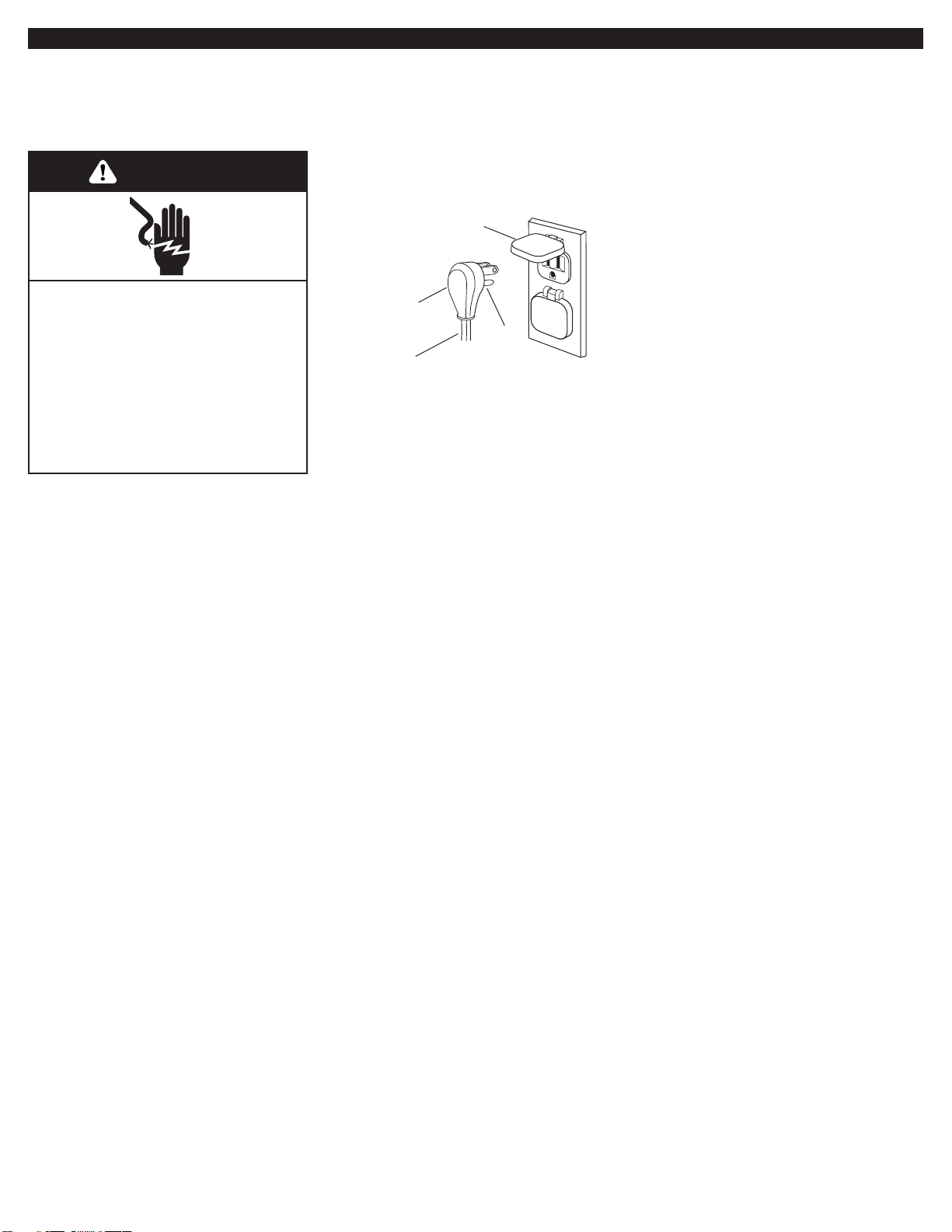
Electrical Shock Hazard
Plug into a grounded 3-prong outlet.
Do not remove ground prong.
Do not use an adapter.
Do not use an extension cord.
Failure to follow these instructions
can result in death, fire, or
electrical shock.
WARNING
If codes permit and a separate ground
wire is used, it is recommended that a
qualified electrician determine that the
ground path is adequate.
Check with a qualified electrician if you
are not sure whether the grill is properly
grounded.
Do not ground to a gas pipe.
A 120-volt, 60-Hz, AC-only, 15-ampere,
electrical supply is required.
Recommended ground method
A grounded 3-prong outdoor outlet
grounded in accordance with the National
Electrical Code ANSI/NFPA 70** or
Canadian Electrical Code (C22.1*) — and
local codes and ordinances.
Copies of the standards listed above may be
obtained from:
*CSA International
8501 East Pleasant Valley Rd.
Cleveland, Ohio 44131-5575
** National Fire Protection Association
One Batterymarch Park
Quincy, Massachusetts 02269
3-prong polarized
ground-type outdoor
outlet
power
supply cord
3-prong
ground plug
ground
prong
pins
7
Installation
Instructions —
Portable Outdoor
Grill
Excessive Weight Hazard
Use two or more people to move
and install grill.
Failure to do so can result in back
or other injury.
WARNING
sear plate
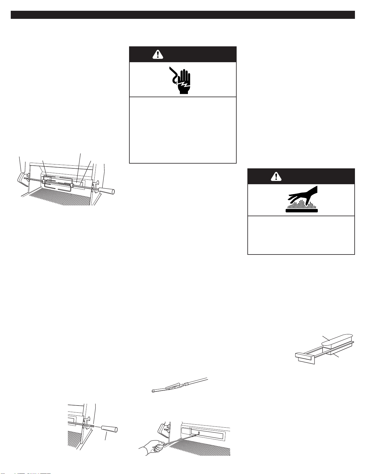
6.Remove sear plates and set aside.
burner
remove
tiedowns
7.Remove tiedowns from burners
and warming shelf.
8.Reinstall sear plates. Make sure
sear plates are resting on pins.
9.Open cabinet doors and remove
L.P./propane gas tank.
11.Turn on the gas supply.Wait a
few minutes for gas to move through the
gas line.
12.Test all connections by brushing
on an approved non-corrosive leakdetection solution. Bubbles will show a
leak. Correct any leak found.
13.Go to “Checking and adjusting
the burners” section.
warming
shelf
remove
tiedowns
cover
extension
burner
grate
5.Carefully lift off grill grates and set
aside.
WARNING
Explosion Hazard
Securely tighten all gas connections.
If connected to LP, have a qualified
person make sure gas pressure does
not exceed 11” (28 cm) water column.
Examples of a qualified person
include:
licensed heating personnel,
authorized gas company personnel,
and
authorized service personnel.
Failure to do so can result in death,
explosion, or fire .
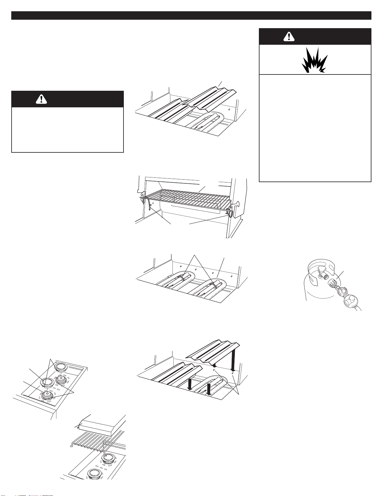
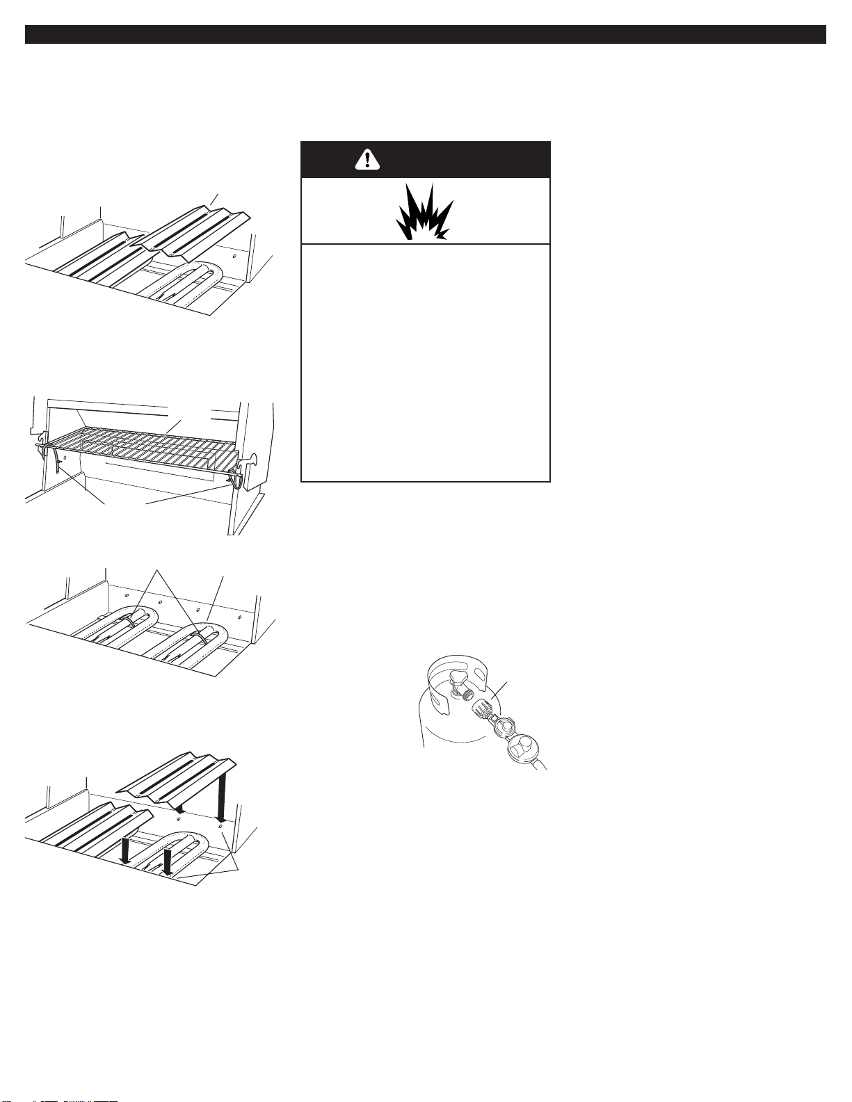
10.Make gas connections.
L.P./propane
(supplied):The 20 lb. L.P.
tank is located in the compartment below
grill. Remove tank and take to an
authorized dealer to be filled. Reinstall
tank and screw the hose/ regulator
assembly to tank as shown.
The pressure
regulator and
hose assembly
supplied with
the grill must
be used.
Replacement
pressure
regulator and hose assembly specific to
your model, is available from your outdoor
grill dealer.
If converting to natural gas, see
conversion kit requirements and “Gas
supply requirements” section. Follow
instructions included with kit.
hose/regulator
assembly
burner
cap
burner
notch
alignment
tab
1.Move grill into desired outdoor
location.
2.Open the hood.
3.For models equipped with
rotisserie, remove the rotisserie’s skewer
from the grill.
4.
For models with side burners.
Remove side burner cover from the top of
the carton that is located on the grill
grate. Remove bubble wrap from side
burner cover and set aside.
Open carton located on the grill grate.
Remove side burner grate, unwrap and
set aside.
Remove burners and burner caps from
carton and unwrap. Install each set of
burners and caps inside the side burner
cavity as shown.
Install side
burner grate
and cover
(with extension
toward grill)
as shown.
Properly dispose
of all packing
material.
8
This installation must conform with local
codes and ordinances**. In the absence of
local codes, installations must conform with
either the National Fuel Gas Code ANSI
Z223.1, or CAN/CGA-B149.1* Natural Gas
and Propane installation code.
Natural Gas Use
If converted to Natural Gas
Copies of the standards listed may
be obtained from:
* CSA International
8501 East Pleasant Valley Rd.
Cleveland, Ohio 44131-5575
** for local codes, contact your local
building inspector
WARNING
Explosion Hazard
Use a new AGA or CSA approved
“outdoor” gas supply line.
Securely tighten all gas connections.
Failure to do so can result in death,
explosion, or fire .
1.Make gas connections.
A combination of pipe fittings must be
used to connect the grill to the existing
gas line.
rear of
grill
1/2" grill
gas pipe
flexible gas
connector
• If local codes per mit, use an outdoor
flexible stainless steel tubing gas
connector, design-certified by AGA or
CSA International, to connect the grill to
the rigid gas supply line. 5/8" diameter
line is recommended. Using a wrench to
tighten, connect the gas supply to the
grill. Use pipe joint compound on all nonflared male threads. Do not kink or
damage the flexible connector when
moving the grill.
• Pipe-joint compounds suitable for use
with L.P. gas must be used. Do not use
Teflon
®
tape.
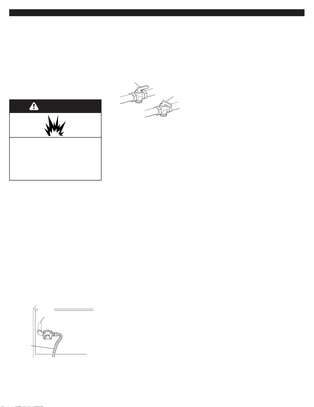
valve open
2.Open shutoff valve in the gas
supply line.The valve is open when the
handle is parallel to the gas pipe.
Test all connections by brushing on an
approved non-corrosive leak-detection
solution. Bubbles will show a leak. Correct
any leak found.
valve closed
®Teflon is a registered trademark of E.I. Du Pont
de Nemours and Company.
9
Installation
Instructions —
Built-In Outdoor
Grill
(non-combustible
construction)
2.Make gas connections.
A combination of pipe fittings must be
used to connect the grill to the existing
gas line.
This installation must conform with local
codes and ordinances**. In the absence of
local codes, installations must conform
with either the National Fuel Gas Code
ANSI Z223.1, or CAN/CGA-B149.1*
Natural Gas and Propane installation code.
Excessive Weight Hazard
Use two or more people to move
and install grill.
Failure to do so can result in back
or other injury.
WARNING
Natural Gas Use
5.Open the hood.
valve open
IMPORTANT: If grill is to be installed in a
combustible enclosure, return this unit
and replace it with the model which is
manufactured for use in a combustible
enclosure.
rear of
grill
1/2" grill
gas pipe
flexible gas
connector
3.Open shutoff valve in the gas
supply line.The valve is open when the
handle is parallel to the gas pipe.
4. Test all connections by brushing
on an approved non-corrosive leakdetection solution. Bubbles will show a
leak. Correct any leak found.
• If local codes per mit, use an outdoor
flexible stainless steel tubing gas
connector, design-certified by AGA or
CSA International, to connect the grill to
the rigid gas supply line. 5/8" diameter
line is recommended. Using a wrench to
tighten, connect the gas supply to the
grill. Use pipe joint compound on all nonflared male threads. Do not kink or
damage the flexible connector when
moving the grill.
• Pipe-joint compounds suitable for use
with L.P. gas must be used. Do not use
Teflon
®
tape.
valve closed
®Teflon is a registered trademark of E.I. Du Pont
de Nemours and Company.
WARNING
Fire Hazard
Do not use grill near combustible
materials.
Do not store combustible materials
near grill.
Doing so can result in death or fire.
WARNING
Fire Hazard
Do not install this grill on or near
combustible materials.
Doing so can result in death or fire.
Copies of the standards listed may
be obtained from:
* CSA International
8501 East Pleasant Valley Rd.
Cleveland, Ohio 44131-5575
** for local codes, contact your local
building inspector
WARNING
Explosion Hazard
Securely tighten all gas connections.
If connected to LP, have a qualified
person make sure gas pressure does
not exceed 11” (28 cm) water column.
Examples of a qualified person
include:
licensed heating personnel,
authorized gas company personnel,
and,
authorized service personnel.
Failure to do so can result in death,
explosion, or fire .
1.Place grill into outdoor enclosure,
but leave enough room in back to connect
to gas supply.
burner
cap
burner
notch
alignment
tab
6.For models equipped with
rotisserie, remove the rotisserie’s skewer
from the grill.
7.
For models with side burners.
Remove side burner cover from the top of
the carton that is located on the grill
grate. Remove bubble wrap from side
burner cover and set aside.
Open carton located on the grill grate.
Remove side burner grate, unwrap and
set aside.
Remove burners and burner caps from
carton and unwrap. Install each set of
burners and caps inside the side burner
cavity as shown.
Install side
burner grate
and cover
(with extension
toward grill)
as shown.
Properly dispose
of all packing
material.
cover
extension
burner
grate
10
burner
remove
tiedowns
sear plate
9.Remove sear plates and set aside.
10.Remove tiedowns from burners
and warming shelf.
12.Carefully slide grill completely
into outdoor enclosure.
13.Now go to the "Checking and
Adjusting Burners Section."
warming
shelf
remove
tiedowns
pins
8.Carefully lift grill grates off of grill
area and set aside.
If converted to
L.P. Gas
2.Turn on the gas supply.Wait a few
minutes for gas to move through the gas
line.
3.Test all connections by brushing on
an approved non-corrosive leak-detection
solution. Bubbles will show a leak. Correct
any leak found.
4.Go to “Checking and adjusting the
burners” section.
WARNING
Explosion Hazard
Securely tighten all gas connections.
If connected to LP, have a qualified
person make sure gas pressure does
not exceed 11” (28 cm) water column.
Examples of a qualified person
include:
licensed heating personnel,
authorized gas company personnel,
and,
authorized service personnel.
Failure to do so can result in death,
explosion, or fire .
1.Make gas connections.
L.P./propane
(supplied):The 20 lb. L.P.
tank is located in the compartment below
grill. Remove tank and take to an
authorized dealer to be filled. Reinstall
tank and screw the hose/ regulator
assembly to tank as shown.
The pressure
regulator and
hose assembly
supplied with the
grill must be used.
Replacement
pressure regulator
and hose
assembly specific to your model, is
available from your outdoor grill dealer.
If converting to natural gas, see
conversion kit requirements and “Gas
supply requirements” section. Follow
instructions included with kit.
hose/regulator
assembly
11.Reinstall sear plates. Make
sure sear plates are resting on pins.
11
6.
Tighten air shutter adjustment screw.
7.
Replace burner sear plates and grates.
8.
Ignite burner to check flames. See
“Sear burner flame characteristics.”
Repeat Steps 1 through 8 above if needed.
Only adjust the burners that need
adjustment.
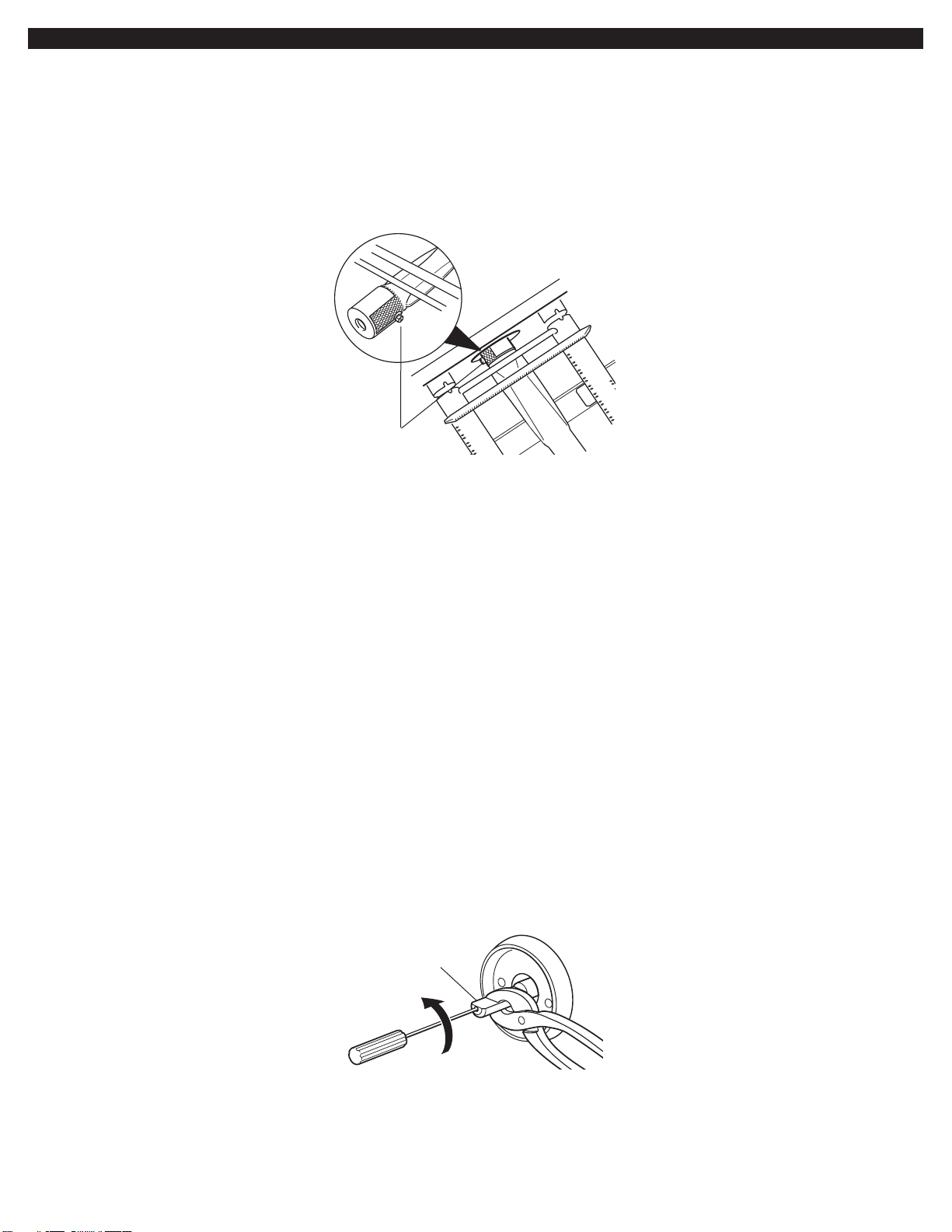
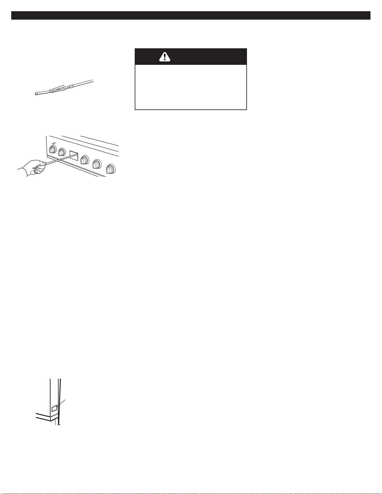
Low flame adjustment:
If flame goes out on the “LO” setting, the
low flame setting must be adjusted.
1.
Turn off the valve and wait until grill
and burners are cool.
2.
Remove grill grates, sear plates.
3.
Light grill using information in the
“Lighting the grill” section.
4.
Turn burner to its lowest setting and
remove knob.
5.
Hold valve stem with pliers and insert a
thin flat-blade screwdriver into the shaft.
6.
Watch the flame and slowly turn the
screwdriver counter-clockwise.
7.
Adjust flame to minimum stable flame.
8.
Replace the control knob and turn off
the burner.
9.
Repeat Steps 3 through 8 for each
burner if needed.
10.
Replace the sear plates and grates
after the burners have cooled.
5.
Remove burner and loosen air shutter
adjustment screw.
a.
If flame is yellow (not enough air),
turn air shutter counter-clockwise.
b.
If flame is noisy or lifts away from
burner (too much air), tur n air
shutter clockwise.
Adjustment should be from 1/8" to 1/4".
Adjusting the air shutters:
1.
Light grill using information in the
“Lighting the grill” section.
2.
Observe flame to determine which
burners need adjustment and how the
flame is acting. See “Sear burner
flame characteristics” above.
3.
Turn off the valve and wait until grill
and burners are cool.
4.
Remove grill grates, sear plates.
air shutter
adjustment screw
Checking and adjusting the burners
The burners are tested and factory-set for
most efficient operation. However,
variations in gas supply and other
conditions may make minor adjustments
to air shutter or low flame setting
necessary. Adjustments must be done by
a qualified service technician.
valve stem
NOTE: No adjustment can be made to
the infrared rotisserie burner (not used on
all models) or smoker tray burner(s).
Checking and adjusting the grill burner
flames requires removing the grate and
sear plates.
Sear burner flame characteristics:
The flames of the grill burners and
surface burners (not used on all models)
should be blue and stable with no
excessive noise or lifting (L.P./propane
gas flames will have a slightly yellow tip).
A yellow flame indicates not enough air.
If flame is noisy or lifts away from the
burner, there is too much air. Some
yellow tips on flames when the burner is
set to HI setting are acceptable as long
as no carbon or soot deposits appear.
Check that burners are not blocked by
dirt, debris, insect nests, etc. and clean
as necessary.If they are clean, adjust air
shutters as needed.
IMPORTANT:
Before adjusting air
shutters, let burners cool down.
12
Remove side burner cover. Do not light
burners with the cover on.
Lighting the side burner
IMPORTANT:
Light only one burner at a
time.
1. Do not lean over burners. Push in and
turn to "LITE" the control knob for the
burner you wish to use.
2. Push in the burner ignitor button.You
will hear the “snapping” sound of the
spark. Keep the burner ignitor button
pushed in until burner lights. Make sure
burner is lit. Repeat for the other
burner as needed.
IMPORTANT:
If burner does not light immediately, turn the
burner knob to “OFF” and wait 5 minutes
before relighting.
Using the side burner
IMPORTANT:
Light only one burner at a
time.
1. Do not lean over burners. Push in and
turn to "LITE" the control knob for the
burner you wish to use.
2. Push in the burner ignitor button.You
will hear the “snapping” sound of the
spark. Keep the burner ignitor button
pushed in until burner lights. Make sure
burner is lit. Repeat for each of the
other burners as needed.
IMPORTANT:
If burner does not light immediately, turn the
burner knob to “OFF” and wait 5 minutes
before relighting.
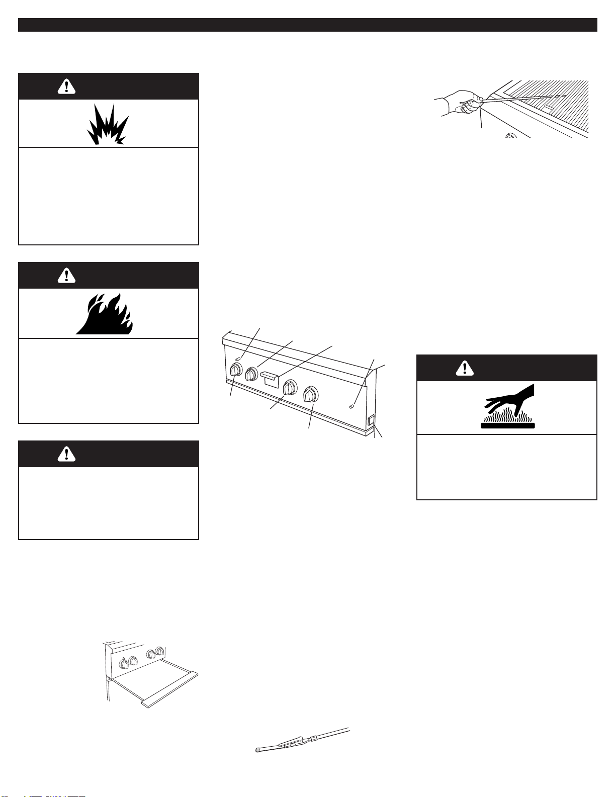
infrared
burner
control
knob
smoker
tray
smoker tray
burner
control knob
grill burner
control knob
grill burner
control knob
ignitor battery
compartment
red button
burner
ignitor
button
Grill Use
Using your grill
Prepare the gas supply
1. Open the hood completely.Do not light
burners with the hood closed.
2. Make sure
control knobs are
turned to OFF.
The drip pan
must be in place
and pushed all
the way to the
back.
WARNING
Fire Hazard
Do not use grill near combustible
materials.
Do not store combustible materials
near grill.
Doing so can result in death or fire.
WARNING
Explosion Hazard
Do not store fuel tank in a garage
or indoors.
Do not store grill with fuel tank in a
garage or indoors.
Failure to follow these instructions
can result in death, explosion, or fire.
Food Poisoning Hazard
Do not let food sit for more than
one hour before or after cooking.
Doing so can result in food
poisoning or sickness.
WARNING
Turn the gas supply on:
1. For portable grills using an L.P./
propane gas cylinder:
Slowly open the cylinder valve;do not
“snap” open.
NOTE:
If flow limiting device does
activate, your grill may not light. If your
grill does light, the flames will be low
and will not heat properly. Turn cylinder
valve and all control knobs off and wait
30 seconds. After shutting off the
cylinder, very slowly open cylinder
valve and wait 5 seconds before
lighting.
2. For grills using gas supply source other
than L.P. gas cylinder:
Turn the shut off valve to open position
from the front of gas supply line.
4. Carefully guide the lit match between
the grill grate and one of the slots in
the sear plate.
5. Push in and turn the burner knob to
“LITE” for the burner closest to the lit
match.The burner will light immediately.
6. Repeat steps 2 through 5 for each
main burner.
7. Replace manual lighting extension
inside the drip tray.
IMPORTANT:
If burner does not light immediately, turn the
burner knob to “OFF” and wait 5 minutes
before relighting.
If any burners do not light after attempting
to manually light them, contact the
KitchenAid Assistance Center.
Lighting the grill
drip pan
Manually lighting main grill burners
1. Remove the manual lighting extension
from inside the drip tray.
2. Attach a match to the clip.
3. Strike the match to light it.
WARNING
Burn Hazard
Do not let the burner flame extend
beyond the edge of the pan.
Doing so can result in burns.
13
Using the rotisserie
For best cooking results, do not use main
grill burners when using the rotisserie.
The rotisserie system is designed to cook
food from the rear using intense, searing
infrared heat.
1. Remove warming shelf.
2. Mount rotisserie motor on the gr ill's
mounting bracket.Position it securely
into support bracket slots.
3.To load the spit rod, slide one of the
rotisserie forks onto the spit rod with
prongs facing away from handle.
4. Push spit rod through the center of the
food, then slide second rotisserie fork
into position.
5. Center the food and rotisserie forks on
spit rod and tighten wing nuts on the
rotisserie forks. If necessary, secure
loose food portions with butcher's
string only. Never use nylon or plastic
string which will melt and ruin the food.
6. Once the food is positioned on spit rod,
place pointed end of rod into rotisserie
motor and lower spit rod onto supports
at either side of the grill.
IMPORTANT: On Models KFGR292LSS,
KFGR382LSS and
KBGN292LSS, remove
the handle from the spit
rod when using the side
burner.The handle will
get “HOT” and failure to
remove it will cause the
handle to crack and
melt.
rotisserie
fork
motor
spit rod
back infrared burner
7. Plug single-prong plug into rotisserie
motor.
8. Plug 3-prong plug into a grounded
3-prong outlet.
To avoid product damage when not using
the rotisserie, remove motor and store
indoors. Remove spit rod and forks. Store
out of reach of children.
Lighting the infrared
(rotisserie) burner
1. Push in and tur n rotisserie burner knob
to “LITE”.
2. At the same time, push in both red
button (left hand side) and burner
ignitor button (right hand side).You will
hear a “snapping” sound.
3.When infrared burner lights, release
the burner ignitor button but continue
pressing the red button for another 5 to
10 seconds.
IMPORTANT:
If the rotisserie burner does not light
immediately, turn the burner knob to “OFF”,
wait 5 minutes before relighting.
Electrical Shock Hazard
Plug into a grounded 3-prong outlet.
Do not remove ground prong.
Do not use an adapter.
Do not use an extension cord.
Failure to follow these instructions
can result in death, fire, or
electrical shock.
WARNING
Manually lighting infrared burner
1. Remove the manual lighting extension
from inside the drip tray.
2. Attach a match to the clip.
3. Strike the match to light it.
4. Carefully hold the lit match close to the
infrared burner.
Using the smoker box(es)
Your grill may have one or two slide-out
smoker boxes that can be used with the
main grill burners or the rotisserie.
The smoker trays are designed for easy
use. After deciding which wood chips to
use, follow the instructions on wood chip
packaging. Small size chips or pellets are
recommended.
1. Slide box and chip cover out of smoker
compartment.
2. Remove cover
from box.Turn
cover over and
fill with
prepared
chips.
3.Turn smoker box over and place over
chip cover. Hold cover and box together
and turn right side up.
4. Slide box and cover back into smoker
compartment.
Light the smoker burner(s) 5 minutes
ahead of time to start them smoking. The
specially-designed smoker will smoke the
food while the grill burners or rotisserie
cooks it. Keeping the hood closed as
much as possible will maximize the
smoking effect.
WARNING
Burn Hazard
Do not remove the smoker box
when grill is hot.
Doing so can result in burns.
5. Push in and turn the infrared burner
control knob to “LITE”.
6. Push in the red button above the
infrared burner control knob, the burner
will light immediately. Hold this button
in for 5 to 10 seconds.
7. Repeat steps 3 through 6 for each
infrared burner.(Number of infrared
burners varies by model.)
8. Replace manual lighting extension
inside the drip tray.
IMPORTANT:
If the infrared burner does not light
immediately, turn the infrared burner
control knob to “OFF” and wait 5 minutes
before relighting.
chip cover
smoker box
Manually lighting the burners
1. Use a paper match to light the burners.
2. Push in and turn the burner knob to
“LITE” for the burner closest to the lit
match.The burner will light immediately.
IMPORTANT:
If burner does not light immediately, turn the
burner knob to “OFF” and wait 5 minutes
before relighting.
If any burners do not light after attempting
to manually light them, contact the
KitchenAid Assistance Center.
remove
handle
14
Grilling Tips
Before Grilling
• Thaw food items before grilling.
• Preheat grill on high (use all grill
burners) 7-10 minutes. The hood must
be closed during preheating. Do not use
back infrared burner for preheating.
Preheating provides the high heat
needed to brown and seal the juices.
• Shorten the preheat time when grilling
high-fat cuts of meat or poultry, such as
chicken thighs.This will help reduce
flare-ups.
• Lightly oil the grill or the food when
cooking low-fat cuts of meat, fish or
poultry, such as lean hamburger patties,
shrimp or skinless chicken breasts.
• Too much oil can cause gray ash to
deposit on food.
• Trim excess fat from meats prior to
cooking to prevent flare-ups.
• Make vertical cuts at 2" intervals around
the fat edge of meat to help prevent the
meat from curling while cooking.
• Add seasoning or salt only after the
cooking is finished.
During Grilling
• Turn foods only once. Juices are lost
when meat is turned several times.
• Turn meat just when juices begin to
appear on the surface.
• Avoid puncturing or cutting the meats to
test doneness.This allows juices to
escape.
• It may be necessary to lower the heat
setting for foods that cook a long time or
are marinated or basted in a sugary
sauce.
• If using a high flame, add barbecue
sauce only during the last 10 minutes of
cooking to avoid burning the sauce.
• The degree of doneness is influenced
by the type of meat, cut of meat (i.e.
size, shape and thickness), heat setting
selected, and length of time on the grill.
• With the grill cover open the cooking
time will be longer.
Smoker Box
The smoker box is a tray that holds wood
chips or pellets that provide a smoky
flavor when foods are cooked on the grill
or rotisserie. For best results the hood
should be down for most of the cooking
time.
• The amount and size of chips and
length of cooking time determine the
degree of smoke flavor.
• When using wood chips or wood pellets
always follow the package directions.
For increased smoking, soak chips in
water prior to placing in the smoker box.
Guide to Wood Chips or Pellets:
Alder: A medium, tar t smoke taste.
Superb on salmon and other fish, chicken
or game.
Maple: Sweet, hear ty smoke flavor. Best
with fish, jerky or bacon.
Apple: A light, sweet flavor. Superb with
poultry, ham or sausage.
Hickory: Heavy smoke flavor. Best with
beef, pork or game.
Mesquite: A light smoke flavor. Best with
fish, poultry or beef.
Oak: Heavy smoke flavor. Best with beef,
lamb or pork.
Pecan: A rich, sweet, versatile flavor.
Can be used with anything.
Grapevine: A strong smoke flavor. Best
with beef or poultry.
Cooking Methods
Direct Heat
Cooking by Direct Heat means the food is
placed on grill grates directly above
lighted burners. Hood position affects total
cooking time.
Direct Heat sears the food. Searing is a
process that seals natural juices in food
by cooking with intense heat for a shor t
period of time.While juices stay inside,
the outside is browned with a flavorful
grilled coating.
Indirect Heat
For best results, do not select the Indirect
Heat cooking method when it is windy.
Cooking by Indirect Heat means the food
is placed on the grill grate above an
unheated burner, allowing heat from
lighted burner(s) on either side to cook
the food.
If possible, turn on two burners. Cook
with the hood down.This will shorten the
cooking time.
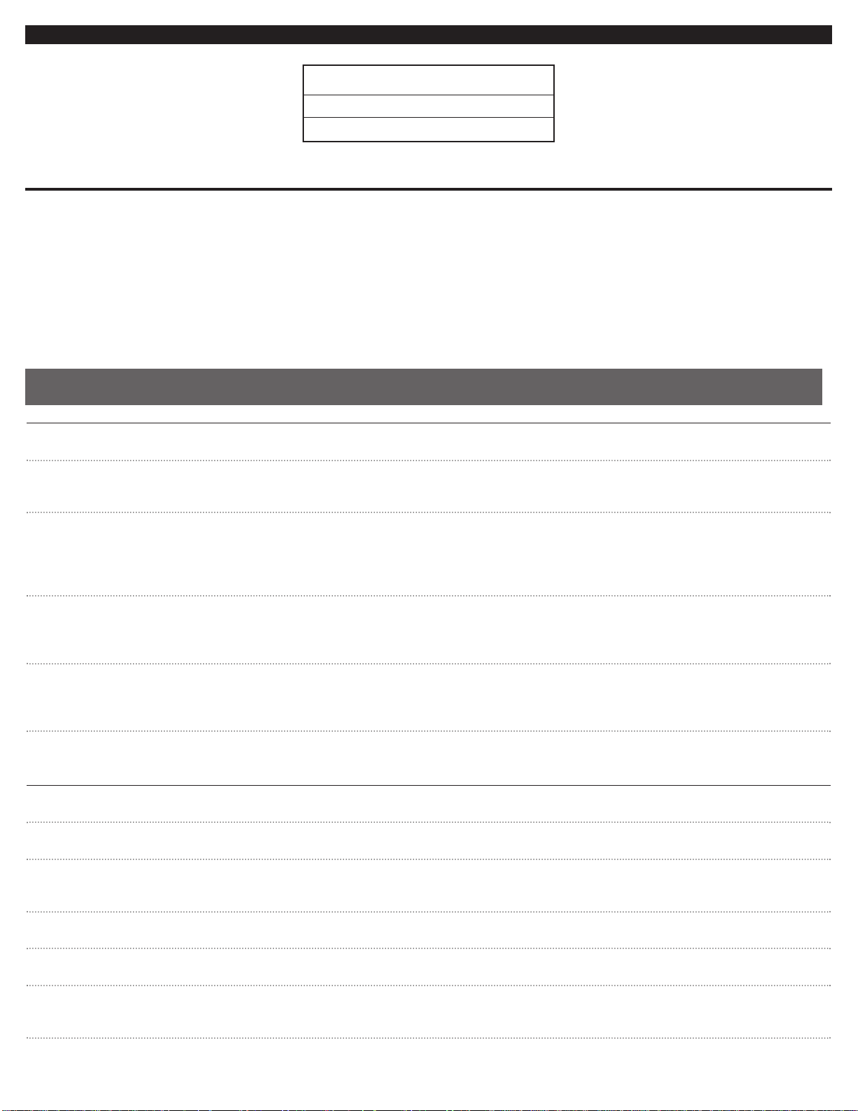
1. Lift up at bottom of batter y tray and
slide battery tray out.
2. Remove battery (or batteries) and
replace with alkaline 9-volt battery (or
batteries).
3. Slide batter y tray back into
compartment.
Your model may have one or two ignitor
batteries. If ignitors stop sparking, the
battery (or batteries) should be replaced.
Replacing the ignitor battery
lift up and
slide out tray
Grill Care
Food Poisoning Hazard
Do not let food sit for more than
one hour before or after cooking.
Doing so can result in food
poisoning or sickness.
WARNING
Manually lighting smoker burner
1. Remove smoker tray.
2. Remove the manual lighting extension
from inside the drip tray.
3. Attach a match to the clip.
4. Strike the match to light it.
5. Carefully guide the lit match into the
smoker chamber area where the tray
was removed.
6. Push in and tur n the knob for the
smoker burner to “LITE”, the burner will
light immediately.
7. Replace smoker tray.
8. Repeat steps 1 through 6 for each
smoker burner.(Number of smoker
burners varies by model.)
9. Replace manual lighting extension
inside the drip tray.
IMPORTANT:
If the smoker burner does not light
immediately, turn the burner knob to “OFF”,
wait 5 minutes before relighting.
Always allow box to cool before removal
or cleaning.
15
Grilling Chart
Food
Cooking Method/
Time Special Instructions
Burner Setting
Beef
Hamburgers DIRECT Medium (160°F) Grill, turning once.
1/2 to 3/4 inch thick Medium 10-15 minutes total
Roasts
Rib Eye, Sirloin INDIRECT Med-Rare (145°F) to Medium (160°F) Tent with foil first 45-60 minutes
Medium/OFF/Medium 32-40 minutes per lb. of cooking time.
Steaks
Porterhouse, Rib DIRECT Med-Rare (145°F) to Medium (160°F) Rotate steaks 1/4 turn to create
T bone, Top Loin Medium 11-16 minutes total criss-cross grill marks.
Sirloin
1 inch
Porterhouse, Rib DIRECT Med-Rare (145°F) to Medium (160°F)
T bone, Top Loin Medium 18-25 minutes total
Sirloin
1-1/2 inch
Top Round or DIRECT Med-Rare (145°F) to Medium (160°F)
Shoulder/Chuck Medium 22-29 minutes total
(London Broil)
1-1/2 inch thick
Flank DIRECT Med-Rare (145°F)
1/2 inch thick Medium 11-16 minutes total
Pork
Chops, 1 inch thick DIRECT Medium (160°F)
Medium to Med-Low 12-20 minutes total
1-1/2 inch thick DIRECT Medium (160°F)
Medium to Med-Low 30-40 minutes total
Ribs INDIRECT Medium (160°F) Grill, turning occasionally. During last few
2-1/2 to 4 lbs. Med/OFF/Med 40-60 minutes total minutes brush with barbecue sauce if
desired.When done, wrap in foil 1 hour.
Roast. Boneless DIRECT Medium (160°F) Turn during cooking to brown on all sides.
Tenderloin 1 lb Medium 18-22 minutes total
Ham, Half INDIRECT Reheat (140°F) Wrap entire ham in foil and put on grill
8 to 10 lbs. Med/OFF/Med 2 – 2-1/2 hours total without pan or drip pan.
Ham Steak DIRECT Reheat (140°F)
Precooked Preheat Medium 7-10 minutes total
1/2 inch thick Grill Medium
Hot Dogs DIRECT Reheat (145°F) Slit skin if desired.
Medium 5-10 minutes total
Indirect Cooking
Place food only on the grill grate over the
OFF burners.
Burner
1234
27" grill ON OFF — —
36" grill ON OFF ON —
• Knobs have High, Medium and Low setting for flame adjustment.
• Heat settings indicated are approximate.
• Grilling time based on heating two adjacent burners with food
placed on grate between burners (Direct).
• Timings are affected by weather conditions.
• Remove excess fat from edge of chops and steaks. Score
remaining fat at 2-inch intervals to prevent curling.
• When 2 temperatures are provided, example: Medium to
Medium-Low, star t with the first and adjust to how it is cooking.
• Cooking times may vary from chart times depending on the type
of fuel, natural gas or L.P..
 Loading...