

KitchenAid KFGD500ESS03, KFGD500EWH03, KFGD500EBL03 Installation Guide

INSTALLATION INSTRUCTIONS
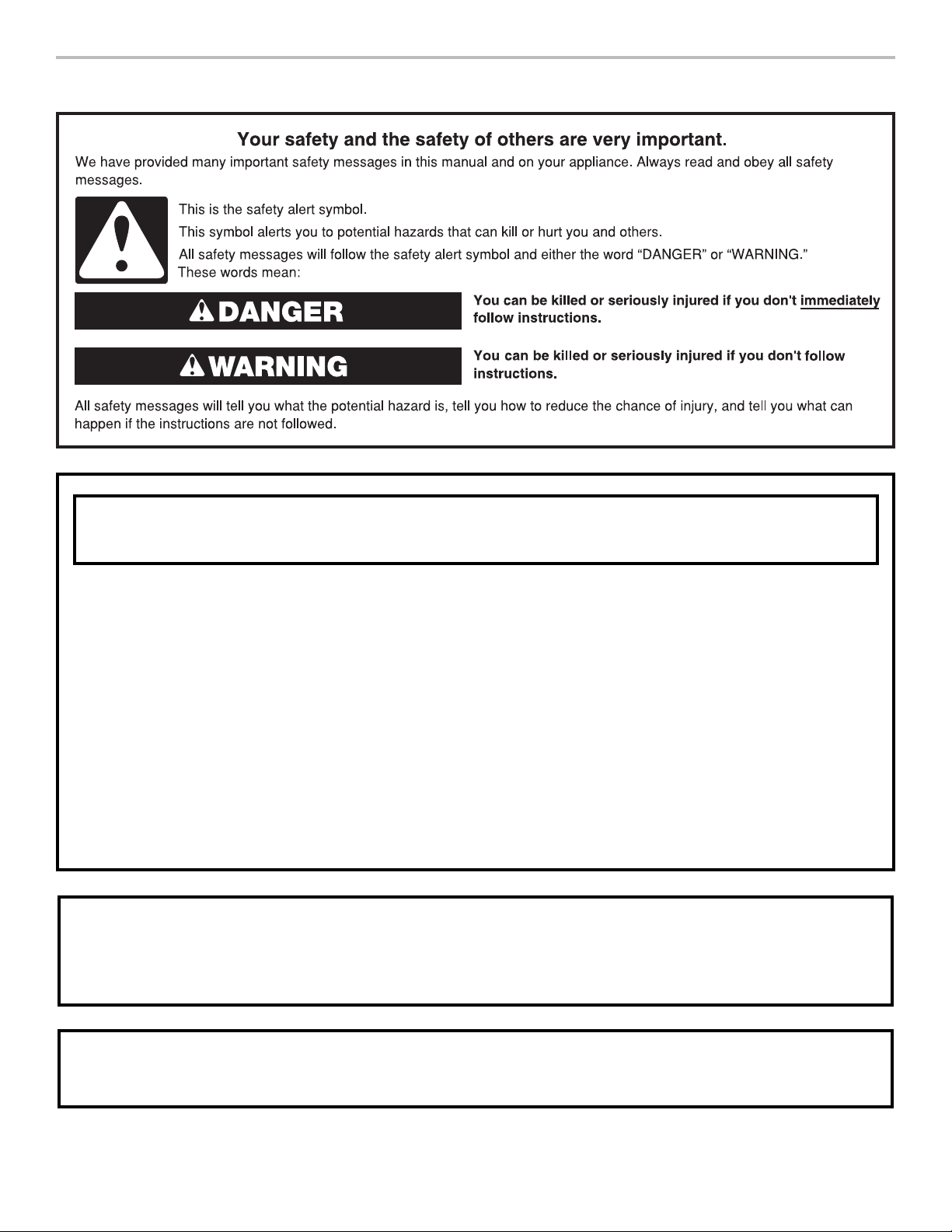
IMPORTANT:
Sa
Installer:
Homeowner: Keep installation instructions for future reference.
30” (76.2 CM) DOUBLE OVEN GAS RANGES
INSTRUCTIONS D’INSTALLATION DES
CUISINIÈRES À GAZ À DOUBLE FOUR DE 30”
(76,2 CM)
Table of Contents Table des matières
RANGE SAFETY .............................................................................2
INSTALLATION REQUIREMENTS .................................................3
Tools and Parts .............................................................................3
Location Requirements ................................................................3
Electrical Requirements ...............................................................5
Gas Supply Requirements ...........................................................6
INSTALLATION INSTRUCTIONS ...................................................7
Unpack Range..............................................................................7
Adjust Leveling Legs ....................................................................7
Install Anti-Tip Bracket .................................................................7
Make Gas Connection .................................................................8
Verify Anti-Tip Bracket Is Installed and Engaged ........................9
Level Range ................................................................................10
Electronic Ignition System .........................................................10
Complete Installation .................................................................11
GAS CONVERSIONS ....................................................................12
Propane Gas Conversion ...........................................................12
Natural Gas Conversion .............................................................15
SÉCURITÉ DE LA CUISINIÈRE ...................................................19
EXIGENCES D’INSTALLATION ...................................................20
Outillage et pièces ......................................................................20
Exigences d’emplacement .........................................................20
Spécifications électriques ..........................................................22
Spécifications de l’alimentation en gaz .....................................23
INSTRUCTIONS D’INSTALLATION .............................................24
Déballage de la cuisinière ..........................................................24
Réglage des pieds de nivellement .............................................24
Installation de la bride antibasculement ....................................24
Raccordement au gaz ................................................................25
Vérifier que la bride anti-basculement est bien installée et engagée . 26
Réglage de l’aplomb de la cuisinière .........................................27
Système d’allumage électronique ..........................................27
Terminer l’installation ..................................................................28
CONVERSIONS DE GAZ ..............................................................29
Conversion pour l’alimentation au propane ..............................29
Conversion pour l’alimentation au gaz naturel ..........................32
ve for local electrical inspector's use.
Leave installation instructions with the homeowner.
IMPORTANT :
Conserver ces instructions à l’usage de l’inspecteur des
installations électriques local.
Installateur : Remettre les instructions d’installation au propriétaire.
Propriétaire : Conserver les instructions d’installation pour
référence ultérieure.
W11116976A
RANGE SAFETY
WARNING: If the information in these instructions is not followed exactly, a fire or
explosion may result causing property damage, personal injury or death.
– Do not store or use gasoline or other flammable vapors and liquids in the vicinity of this
or any other appliance.
– WHAT TO DO IF YOU SMELL GAS:
Do not try to light any appliance.
•
Do not touch any electrical switch.
•
Do not use any phone in your building.
•
Immediately call your gas supplier from a neighbor's phone. Follow the gas supplier's
•
instructions.
If you cannot reach your gas supplier, call the fire department.
•
– Installation and service must be performed by a qualified installer, service agency or
the gas supplier.
WARNING: Gas leaks cannot always be detected by smell.
Gas suppliers recommend that you use a gas detector approved by UL or CSA.
For more information, contact your gas supplier.
If a gas leak is detected, follow the “What to do if you smell gas” instructions.
IMPORTANT: Do not install a ventilation system that blows air downward toward this gas cooking appliance. This type of
ventilation system may cause ignition and combustion problems with this gas cooking appliance resulting in personal injury or
unintended operation.
2

4
In the State of Massachusetts, the following installation instructions apply:
Installations and repairs must be performed by a qualified or licensed contractor, plumber, or gasfitter qualified or licensed by
the State of Massachusetts.
Acceptable Shut-off Devices: Gas Cocks and Ball Valves installed for use shall be listed.
A flexible gas connector, when used,must not exceed 4 feet (121.9 cm).
WARNING
Tip Over Hazard
A child or adult can tip the range and be killed.
Install anti-tip bracket to floor or wall per installation instructions.
Slide range back so rear range foot is engaged in the slot of the anti-tip bracket.
Re-engage anti-tip bracket if range is moved.
Do not operate range without anti-tip bracket installed and engaged.
Failure to follow these instructions can result in death or serious burns to children and adults.
To verify the anti-tip bracket is installed and engaged:
Anti-Tip
Bracket
Range Foot
• Slide range forward.
• Look for the anti-tip bracket securely attached to floor or wall.
• Slide range back so rear range foot is under anti-tip bracket.
• See installation instructions for details.
INSTALLATION REQUIREMENTS
Tools and Parts
Gather the required tools and parts before starting installation.
Read and follow the instructions provided with any tools listed
here.
Tools needed
■ Tape measure
■ Phillips screwdriver
®†
■ Torx
■ Flat-blade screwdriver
■ ¹⁄
T20®† screwdriver
8
” (3.2 mm) flat-blade
screwdriver
■ Level
■ Hand or electric drill
■ Wrench or pliers
■ Pipe wrench
5
■ ¹
⁄16” (23.8 mm)
combination wrench
Parts supplied
Check that all parts are included.
■ Propane/Natural Gas Conversion Kit (located on back of
range near lower side)
■ Burner grates
■ Burner caps
■ Oven racks
■ 2 - #12 x 1
†®TORX and T20 are registered trademarks of Acument Intellectual Properties, LLC.
5
⁄8” screws (for mounting anti-tip bracket)
8
■ ¹⁄
” (3.2 mm) drill bit
■ Marker or pencil
■ Pipe-joint compound
resistant to Propane gas
■ Noncorrosive leak-
detection solution
For Propane/Natural Gas
Conversions
■ ½” (12.7 mm) combination
wrench
9
■
⁄32” (7.0 mm) nut driver
■ Masking tape
■ Anti-tip bracket (taped inside upper oven with package
containing literature)
Anti-tip bracket must be securely mounted to the back wall
or floor. Thickness of flooring may require longer screws to
anchor bracket to subfloor. Longer screws are available from
your local hardware store.
Parts needed
Check local codes and consult gas supplier. Check existing gas
supply and electrical supply. See the “Electrical Requirements”
and the “Gas Supply Requirements” sections.
Location Requirements
IMPORTANT: Observe all governing codes and ordinances. Do
not obstruct flow of combustion and ventilation air.
■ It is the installer’s responsibility to comply with installation
clearances specified on the rating number plate. The rating
number plate is located behind the control panel.
■ The range should be located for convenient use in the
kitchen.
■ Recessed installations must provide complete enclosure of
the sides and rear of the range.
■ To eliminate the risk of burns or fire by reaching over heated
surface units, cabinet storage space located above the
surface units should be avoided. If cabinet storage is to be
provided, the risk can be reduced by installing a range hood
or microwave hood combination that projects horizontally a
minimum of 5” (12.7 cm) beyond the bottom of the cabinets.
■ All openings in the wall or floor where range is to be installed
must be sealed.
3
■ Cabinet opening dimensions that are shown must be used.
Given dimensions are minimum clearances.
■ The floor anti-tip bracket must be installed. To install the
antitip bracket shipped with the range, see “Install Anti-Tip
Bracket” section.
■ Grounded electrical supply is required. See “Electrical
Requirements” section.
■ Proper gas supply connection must be available. See “Gas
Supply Requirements” section.
■ Contact a qualified floor covering installer to check that the
floor covering can withstand at least 200°F (93°C).
■ Use an insulated pad or ¼” (0.64 cm) plywood under range if
installing range over carpeting.
IMPORTANT: To avoid damage to your cabinets, check with
your builder or cabinet supplier to make sure that the materials
used will not discolor, delaminate or sustain other damage. This
oven has been designed in accordance with the requirements
of UL and CSA International and complies with the maximum
allowable wood cabinet temperatures of 194°F (90°C).
Mobile Home - Additional Installation Requirements
The installation of this range must conform to the Manufactured
Home Construction and Safety Standard, Title 24 CFR,
Part 3280 (formerly the Federal Standard for Mobile Home
Construction and Safety, Title 24, HUD Part 280). When such
standard is not applicable, use the Standard for Manufactured
Home Installations, ANSI A225.1/NFPA 501A or with local codes.
In Canada, the installation of this range must conform with the
current standards CAN/CSA-A240-latest edition, or with local
codes.
Mobile home installations require:
■ When this range is installed in a mobile home, it must be
secured to the floor during transit. Any method of securing
the range is adequate as long as it conforms to the
standards listed above.
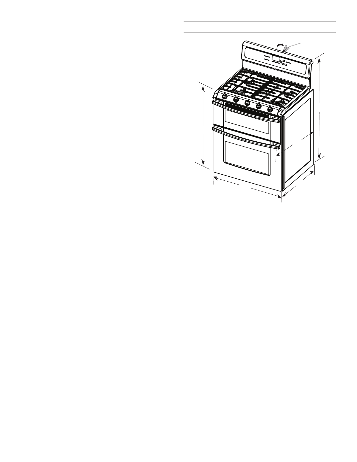
Product Dimensions
A
A. 35³⁄4” ± ¹⁄8” (90.8 ± 0.3 cm)
cooktop height (minimum) with
leveling legs screwed all the way
in
B. Model/serial/rating plates
(located behind the control
panel)*
F
C. 47 3⁄8” ± ¹⁄8” (120.3 ± 0.3 cm)
overall height (minimum) with
leveling legs screwed all the way
in**
2
D. 28¹⁄
” ± ¹⁄4” (72.4 ± 0.6 cm) depth
with handle
8
E 26¹⁄
” to 27¼” ± ¹⁄8” (66.4 to
69.2 cm ± 0.3 cm)***
5
F 29¹
⁄16” ± ¹⁄16” (76.0 ± 0.2 cm)
width
B*
C**
D
E***
*Model/serial/rating plates may be rotated up from behind the
control panel for viewing from the front of the range.
**Range can be raised approximately 1” (2.5 cm) by adjusting
the leveling legs.
***Excludes handle. Dimension given is from wall to front of
oven door and will vary based on electrical outlet receptacle
installation.
4
Cabinet Dimensions
Cabinet opening dimensions shown are for 25” (64.0 cm)
countertop depth, 24” (61.0 cm) base cabinet depth and 36”
(91.4 cm) countertop height.
IMPORTANT: If installing a range hood or microwave hood
combination above the range, follow the range hood or
microwave hood combination installation instructions for
dimensional clearances above the cooktop surface.
Range may be installed with zero clearance to combustible
construction at the rear and on the sides below the cooktop.
30” (76.2 cm) minimum clearance between the top of the
cooking platform and the bottom of an uncovered wood or metal
cabinet.
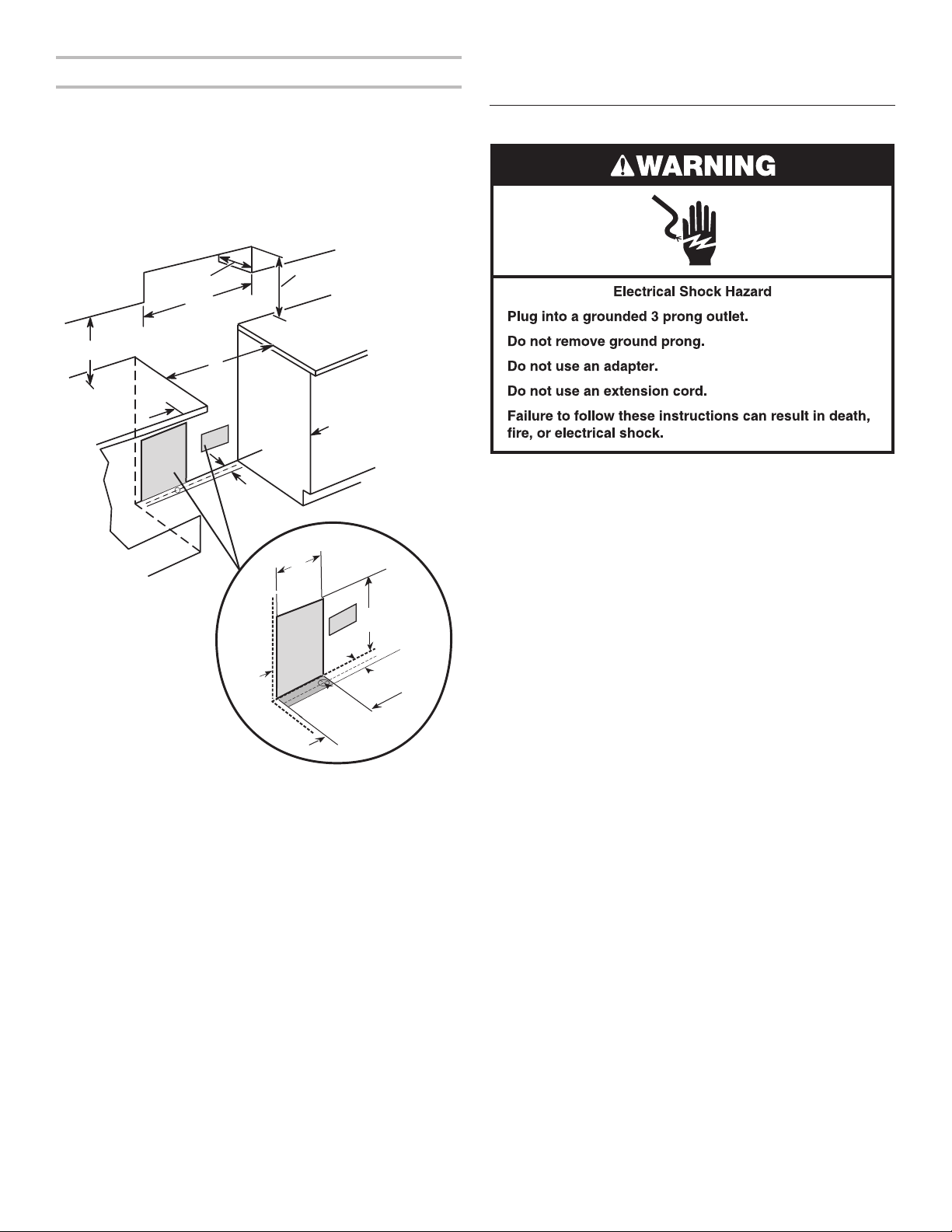
Electrical Requirements
B
D
C
A
E
F
J
I
K
L
G
H
8½"
(21.6 cm)
14"
(35.6 cm)
***
1½"
(3.8 cm)
A. 18” (45.7 cm) upper cabinet to countertop
B. 13” (33.0 cm) upper cabinet depth
C. 30” (76.2 cm) min. opening width
D. For minimum clearance to the top of the cooktop, see NOTE.
E. in U.S.A.: 30” (76.2 cm) min. opening width
in Canada: 31” (78.7 cm) min. opening width
F. 3” (7.6 cm) min. clearance from both sides of the range to the
side wall or other combustible material.
G. Cabinet door or hinges should not extend into the cutout.
H. 3” (7.6 cm) distance from wall
2
I. 1¹⁄
” (3.8 cm) min. from right side cabinet
J. 8” (20.3 cm) width
K. 7” (17.8 cm) min. from floor
L. 2” (5.1 cm) min. from floor
1¼"*
(3.1 cm)
8½" (21.6 cm)**
gas line location
2¼" (5.7 cm)
IMPORTANT: The range must be electrically grounded in
accordance with local codes and ordinances, or in the absence
of local codes, with the National Electrical Code, ANSI/NFPA 70
or Canadian Electrical Code, CSA C22.1.
If codes permit and a separate ground wire is used, it is
recommended that a qualified electrical installer determine that
the ground path is adequate.
A copy of the above code standards can be obtained from:
National Fire Protection Association
1 Batterymarch Park
Quincy, MA 02169-7471
CSA International
8501 East Pleasant Valley Road
Cleveland, OH 44131-5575
■ A 120 volt, 60 Hz., AC-only, 15-amp, fused electrical circuit
is required. A time-delay fuse or circuit breaker is also
recommended. It is recommended that a separate circuit
serving only this cooktop be provided.
■ Electronic ignition systems operate within wide voltage limits,
but proper grounding and polarity are necessary. Check that
the outlet provides 120-volt power and is correctly grounded.
■ The wiring diagram is located on the back of the range in a
clear plastic bag.
*Drill on centerline 1¼” (3.2 cm) from rear wall for gas supply
line.
**Gas lines must be installed within the shaded area to ensure
proper alignment of this oven with cabinets.
***Electrical plugs must be installed within the shaded area to
ensure proper alignment of this oven with cabinets.
NOTE: 24” (61.0 cm) minimum when bottom of wood or metal
cabinet is covered by not less than 1⁄4” (0.64 cm) flame retardant
millboard covered with not less than No. 28 MSG sheet steel,
0.015” (0.4 mm) stainless steel, 0.024” (0.6 mm) aluminum or
0.020” (0.5 mm) copper.
5
A
C
Gas Supply Requirements
WARNING
Explosion Hazard
Use a new CSA International approved gas supply line.
Install a shut-off valve.
Securely tighten all gas connections.
If connected to propane, have a qualified person make
sure gas pressure does not exceed 14" (36 cm) water
column.
Examples of a qualified person include:
licensed heating personnel,
authorized gas company personnel, and
authorized service personnel.
Failure to do so can result in death, explosion, or fire.
Observe all governing codes and ordinances.
IMPORTANT: This installation must conform with all local codes
and ordinances. In the absence of local codes, installation must
conform with American National Standard, National Fuel Gas
Code ANSI Z223.1 - latest edition - or CAN/CGA B149 - latest
edition.
IMPORTANT: Leak testing of the cooktop must be conducted
according to the manufacturer’s instructions.
Gas Supply Line
■ Provide a gas supply line of ¾” (1.9 cm) rigid pipe to the
range location. A smaller size pipe on longer runs may
result in insufficient gas supply. With Propane gas, piping or
tubing size can be ½” (1.3 cm) minimum. Usually,
suppliers determine the size and materials used in the
gas
system.
NOTE:
Pipe-joint compounds that resist the action of
Propane
gas must be used. Do not use TEFLON®† tape.
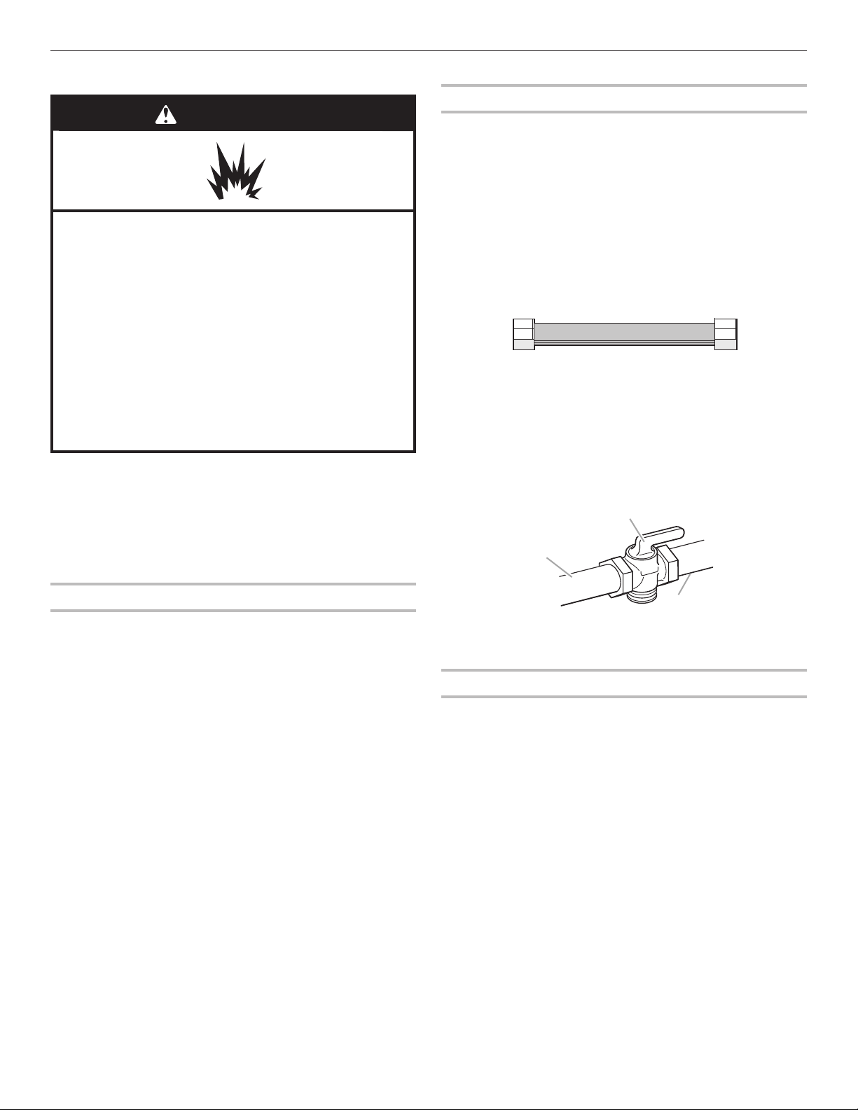
Flexible metal appliance connector:
■ If local codes permit, a new CSA design-certified, 4 to 5
ft (122 to 152.4 cm) long, ½” (1.3 cm) or ¾” (1.9 cm) I.D.,
flexible metal appliance connector may be used for
connecting range to the gas supply line.
1
■ A
/2" (13 mm) male pipe thread is needed for connection
to the female pipe threads of the inlet to the cooktop
pressure regulator.
■ Do not kink or damage the flexible metal tubing when
moving the range.
■ Must include a shut-off valve:
Install a manual gas line shut-off valve in an easily accessible
location. Do not block access to shut-off valve. The valve is
for turning on or shutting off gas to the cooktop.
B
Propane
Type of Gas
Natural gas:
■ This range is factory set for use with Natural gas. See “Gas
Conversions” section. The model/serial rating plate located
behind the control panel has information on the types of gas
that can be used. If the types of gas listed do not include the
type of gas available, check with the local gas supplier.
Propane
Conversion must be done by a qualified service technician.
No attempt shall be made to convert the appliance from the gas
specified on the model/serial rating plate for use with a different
gas without consulting the serving gas supplier. See “Gas
Conversions” section.
gas conversion:
A. Gas supply line
B. Shut-off valve “open” position
C. To range
Gas Pressure Regulator
The gas pressure regulator supplied with this range must be
used. The inlet pressure to the regulator should be as follows for
proper operation:
Natural gas:
Minimum pressure: 5” (12.7 cm) WCP
Maximum pressure: 14”
Propane gas:
Minimum pressure: 11”
Maximum pressure: 14”
Contact local gas supplier if you are not sure about the inlet
pressure.
(35.6 cm) WCP
(27.9 cm) WCP
(35.6 cm) WCP
†®TEFLON is a registered trademark of Chemours.
6
 Loading...