

KitchenAid KESC300H, KESH307H, KESC307H User Manual
KAC-34
TECHNICAL EDUCATION
SELF-CLEANING
SLIDE-IN ELECTRIC
RANGE
Models KESC300H, KESC307H, KESH307H
JOB AID 4317335

FORWARD
This KitchenAid Job Aid, “Self-Cleaning Slide-In Electric Range,” (Part No. 4317335), provides the
technician with information on the installation, operation, and service of the Self-Cleaning SlideIn Electric Range. It is to be used as a training Job Aid and Service Manual. For specific information
on the model being serviced, refer to the “Use and Care Guide,” or “Wiring Diagram” provided with
the electric range.
The Wiring Diagram and Strip Circuits used in this Job Aid are typical and should be used for
training purposes only. Always use the Wiring Diagram supplied with the product when servicing
the unit.
GOALS AND OBJECTIVES
The goal of this Job Aid is to provide detailed information that will enable the service technician to
properly diagnose malfunctions and repair the KitchenAid Self-Cleaning Slide-In Electric Range.
The objectives of this Job Aid are to:
• Understand and follow proper safety precautions.
• Successfully troubleshoot and diagnose malfunctions.
• Successfully perform necessary repairs.
• Successfully return the range to its proper operational status.
WHIRLPOOL CORPORATION assumes no responsibility for any repairs made
on our products by anyone other than Authorized Service Technicians.
Copyright © 2002, Whirlpool Corporation, Benton Harbor, MI 49022
- ii -

TABLE OF CONTENTS
Page
GENERAL............................................................................................................................... 1-1
Safety First......................................................................................................................... 1-1
KitchenAid Model & Serial Number Designations.............................................................. 1-3
Model & Serial Number Label Location ............................................................................. 1-4
Specifications..................................................................................................................... 1-5
KitchenAid Electric Range Warranty.................................................................................. 1-7
INSTALLATION INFORMATION ........................................................................................... 2-1
Electrical Supply Requirements ......................................................................................... 2-1
Moving The Range ............................................................................................................ 2-8
THEORY OF OPERATION ..................................................................................................... 3-1
Air Flow—Rear Panel ........................................................................................................ 3-1
Cooling Fan Air Flow ......................................................................................................... 3-2
The Bimetal Switches ........................................................................................................ 3-3
The Surface Element Limiter ............................................................................................. 3-4
The Door Lock Solenoid & Door Latch Switch................................................................... 3-5
How The Self-Clean Cycle Works ..................................................................................... 3-6
COMPONENT ACCESS ......................................................................................................... 4-1
Component Locations ........................................................................................................ 4-1
Removing The Control Panel, An Infinite Switch & Bimetal Switch ................................... 4-2
Removing The Electronic Oven Control And An Indicator Light ........................................ 4-4
Removing An Element & Limiter And The Hot Surface Indicator Assembly ...................... 4-5
Removing The Cooktop Glass ........................................................................................... 4-7
Removing The Door Latch Assembly & The Door Switch ............................................... 4-10
Removing The Dual Broil Element And The Hidden Bake Element ................................ 4-12
Removing The Convection Bake Element & Fan Motor .................................................. 4-14
Removing An Oven Light Socket Assembly .................................................................... 4-16
Removing The Meat Probe Jack ..................................................................................... 4-17
Removing The Oven Temperature Sensor ...................................................................... 4-18
Removing A Side Panel ................................................................................................... 4-19
Removing The Double Line Break (DLB) Relay And The Cooling Fan Motor ................ 4-20
Removing The Oven Door ............................................................................................... 4-22
Removing The Decorative Glass, The Oven Door Handle, The Hinges,
And The Oven Door Glass........................................................................................... 4-23
Removing The Oven Door Gasket................................................................................... 4-25
- iii -

Page
COMPONENT TESTING ........................................................................................................ 5-1
Bimetal Switch ................................................................................................................... 5-1
Single Element Infinite Switches........................................................................................ 5-2
Dual Element Infinite Switch (Optional) ............................................................................. 5-3
Surface Elements & Limiters ............................................................................................. 5-4
Door Switch ....................................................................................................................... 5-6
Door Latch Assembly......................................................................................................... 5-6
Hidden Bake Element ........................................................................................................ 5-7
Dual Broil Element ............................................................................................................. 5-7
Convection Bake Element ................................................................................................. 5-8
Convection Fan Motor ....................................................................................................... 5-8
Oven Temperature Sensor ................................................................................................ 5-9
Cooling Fan Motor ............................................................................................................. 5-9
Double Line Break (DLB) Relay....................................................................................... 5-10
DIAGNOSIS & TROUBLESHOOTING ................................................................................... 6-1
Diagnosis ........................................................................................................................... 6-1
Failure / Error Display Codes—Tech Sheet #9753028, Rev. B ..................................... 6-1
Fault Error Code Charts................................................................................................ 6-2
Troubleshooting Charts ..................................................................................................... 6-3
Oven Temperature Calibration .......................................................................................... 6-6
WIRING DIAGRAM & STRIP CIRCUITS ............................................................................... 7-1
Wiring Diagram— #9753028, Rev. B................................................................................. 7-1
Strip Circuits ...................................................................................................................... 7-3
- iv -
GENERAL
SAFETY FIRST
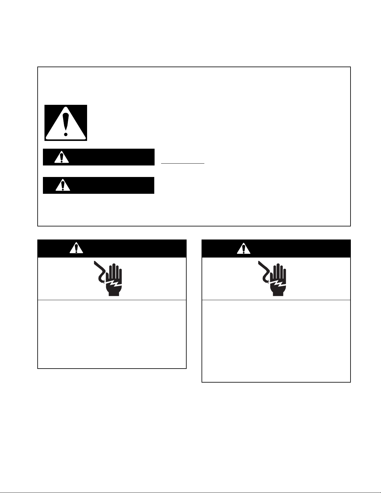
Your safety and the safety of others is very important.
We have provided many important safety messages in this Job Aid and on the appliance. Always
read and obey all safety messages.
This is the safety alert symbol.
This symbol alerts you to hazards that can kill or hurt you and others.
All safety messages will follow the safety alert symbol and either the word
“DANGER” or “WARNING.” These words mean:
You can be killed or seriously injured if you don’t
DANGER
WARNING
All safety messages will tell you what the potential hazard is, tell you how to reduce the chance
of injury, and tell you what can happen if the instructions are not followed.
immediately follow instructions.
You can be killed or seriously injured if you don’t
follow instructions.
WARNING
Electrical Shock Hazard
Disconnect power before servicing.
Replace all parts and panels before
operating.
Failure to do so can result in death or
electrical shock.
WARNING
Electrical Shock Hazard
Plug into a grounded 3-prong outlet.
Do not remove ground prong.
Do not use an adapter.
Do not use an extension cord.
Failure to follow these instructions can
result in death, fire, or electrical shock.
1-1
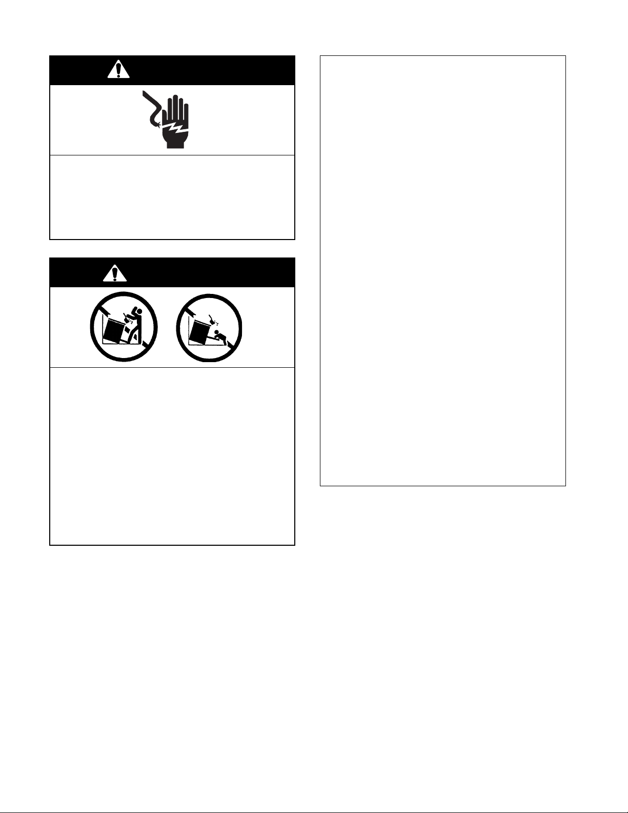
WARNING
Electrical Shock Hazard
Electrically ground range.
Failure to do so can result in death, fire, or
electrical shock.
IMPORTANT
Electrostatic Discharge (ESD)
Sensitive Electronics
ESD problems are present everywhere.
ESD may damage or weaken the electronic control assembly. The new control
assembly may appear to work well after
repair is finished, but failure may occur at
a later date due to ESD stress.
• Use an antistatic wrist strap. Connect the
wrist strap to the green ground connection point, or to an unpainted metal surface in the appliance.
WARNING
Tip-Over Hazard
A child or adult can tip the range
and be killed.
Connect anti-tip bracket to rear
range foot.
Reconnect the anti-tip bracket, if the
range is moved.
Failure to follow these instructions
can result in death or serious burns
to children and adults.
- OR -
• Touch your finger repeatedly to a green
ground connection point, or to an unpainted metal surface in the appliance.
• Before removing the part from its package, touch the antistatic bag to a green
ground connection point, or to an unpainted metal surface in the appliance.
• Avoid touching electronic parts, or terminal contacts. Handle the electronic control assembly by the edges only.
• When repackaging the failed electronic
control assembly in an antistatic bag,
observe the previous instructions.
1-2

KITCHENAID MODEL & SERIAL NUMBER DESIGNATIONS
MODEL NUMBER
MODEL NUMBER K ES C 30 0 H BL 4
INTERNATIONAL SALES IND.
OR MARKETING CHANNEL
IF PRESENT
PRODUCT GROUP
K = KITCHENAID
PRODUCT IDENTIFICATION
DD = DUAL FUEL DROP-IN / SLIDE-IN
DR = DUAL FUEL RANGE
ED = ELECTRIC DROP-IN RANGE
EE = ELECTRIC EYE-LEVEL RANGE
ER = ELECTRIC STANDARD RANGE
ES = ELECTRIC SLIDE-IN RANGE
GD = GAS DROP-IN RANGE
GE = GAS EYE-LEVEL RANGE
GR = GAS STANDARD RANGE
GS = GAS SLIDE-IN RANGE
MERCHANDISING SCHEME
C = CERAMIC GLASS TOP
H = CERAMIC W/HALOGEN
I = IMPERIAL
P = PROFESSIONAL / COMMERCIAL
S = STANDARD
T = TEMPERED GLASS TOP
CAPACITY / SIZE / SERIES / CONFIGURATION
1ST POSITION 2ND POSITION
1 = DROP-IN 0 = 30″ WIDE
2 = DROP-IN / SLIDE-IN COMBO 6 = 36″ WIDE
3 = SLIDE-IN
4 = COMMERCIAL
5 = STANDARD
7 = EYE-LEVEL
8 = 48″
9 = 60″
FEATURES
0 = STANDARD FEATURES
2 = PLUS FEATURES OR SEALED BURNERS
W / GRILL / CONVECTION OVEN
3 = SEALED BURNERS W / GRIDDLE / CONVECTION OVEN
4 = SEALED BURNERS W / GRILL & GRIDDLE / CONVECTION OVEN
5 = DELUXE FEATURES
7 = DELUXE FEATURES / CONVECTION OR
SEALED BURNERS / CONVECTION OVEN
YEAR OF INTRODUCTION
H = 1999, J = 2000, K= 2001, L - 2002
COLOR CODE
BL = BLACK, WH = WHITE, BT = BISCUIT
BS = BLACK ON STAINLESS
ENGINEERING CHANGE (NUMERIC)
SERIAL NUMBER
SERIAL NUMBER IM K 3 1 73981
MANUFACTURING SITE
IM = MONTMAGNY
YEAR OF PRODUCTION
K = 2000, L = 2001, M = 2002
WEEK OF PRODUCTION
31 = 31ST WEEK
PRODUCT SEQUENCE NUMBER
1-3
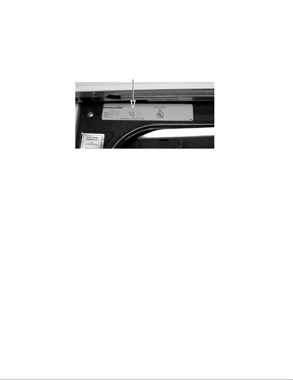
MODEL & SERIAL NUMBER LABEL LOCATION
The Model/Serial Number label location is shown below.
Model & Serial Number Location
(Located Behind Storage Drawer)
1-4
SPECIFICATIONS
Model
Model Description
Dimensions/Specifications
Exterior Dimensions
Height To Maintop (in)
Overall Depth Inc Hrdwr/Hndl (in)
Depth Without Handle (in)
Door Swing (in)
Shipping Weight (lbs)
Exterior
Cabinet Finish
Front Frame
Leveling Legs
Oven Window Size and Type
Removable Door and Hinges
Door Liner Finish
Door Type
Control Panel Location
Control Panel Color
Control Panel Construction
Control Knob Type, #, Fcn
Simmer Specialty Switch
Keep Warm Switch
Cooktop Features
Cooktop Material
Hot Surface Indicator
Burner Box Finish
Cooktop Support Rods
Electric Cooktop Element
Electric Element Configuration
Electric Element Type
Electric Right Front Size
Electric RF Output (w@240/208v)
Electric Left Front Size
Electric LF Output (w@240/208v)
Electric Right Rear Size
Electric RR Output (w@240/208v)
Electric Left Rear Size
Electric LR Output (w@240/208v)
Oven Controls
Oven Control Type
Oven Control Location
Control Lock Out
Delayed Cooking Option
Timer
KESC300H WH/BL/BT KESC307H WH/BT/BS KESH307H WH/BL/BS
Slide-In Slide-In Slide-In Radiant/Halogen
36" 36" 36"
26.75" 26.75" 26.75"
24.5" 24.5" 24.5"
21.75" 21.75" 21.75"
160 160 160
Painted Painted Painted
Porcelain Porcelain Porcelain
Yes Yes Yes
Large/Glass Large/Glass Large/Glass
Yes Yes Yes
Porcelain Porcelain Porcelain
Glass Glass Glass
Front Front Front
White White White
Glass Glass Glass
Infinite Switch Single Blade Infinite Switch Single Blade Infinite Switch Single Blade
Yes Yes Yes
Yes Yes Yes
Ceran Top Ceran Top Ceran Top
4 Neon Cluster 4 Neon Cluster 4 Neon Cluster
Galvanized Galvanized Galvanized
No No No
Yes Yes Yes
6", 7", 8", 9.5" 6", 7", 8", 9.5" 6", 7", 8", 9.5"
Radiant Radiant Radiant
7" 7" 7"
1800W 1800W 1800W/Halogen
9.5" 9.5" 9.5"
2500W/1500W 2500W/1500W 2500W/1500W
8" 8" 8"
2200W 2200W 2200W
6" 6" 6"
1500" 1500" 1500"
EOC EOC EOC
Glass Capacitive Glass Capacitive Glass Capacitive
Front Front Front
Yes Yes Yes
Yes Yes Yes
in EOC in EOC in EOC
1-5
Model
Interior
Main Oven
Cooking System
Cleaning System
Auto Self Clean Latch
Oven Liner Finish
Oven Volume (cu ft)
Oven Height (in)
Oven Width (in)
Oven Depth (in)
Rack Guides #
Oven Racks #
Oven Rack Type & # Each
Oven Rack
Broiler Pan
Broiler Pan Finish
Broiler Pan Grid Finish
Oven Light Number
Main Electric Oven
Hidden Bake Element
Bake (W@240/208v)
Broil Inner Elem (W@240/208v)
Broil Outer Elem (W@240/208v)
Oven Lower Panel/ Door
Drawer/Panel Front
Storage Drawer Liner
Drawer/Panel Height (in)
Drawer/Panel Width (in)
Drawer/Panel Depth (in)
Glides
Lower Drawer Handle Type/Material
Lower Drawer Handle Color
Product Literature
Cookbook
Installation Instructions
Tech Sheet
Use & Care Guide
Other
Agency Approvals
Anti-tip Device With Unit
KESC300H WH/BL/BT KESC307H WH/BT/BS KESH307H WH/BL/BS
Conventional Fan Convection Fan Convection
Self Cleaning Self Cleaning Self Cleaning
Yes Yes Yes
Porcelain Porcelain Porcelain
3.62 cu ft 3.28 3.28
15.75" 15.75" 15.75"
23 1/16" 23 1/16" 23 1/16"
18.25" 16 5/16" 16 5/16"
55 5
23 3
2 Flat
Yes Yes Yes
Yes Yes Yes
Porcelain Porcelain Porcelain
Porcelain Porcelain Porcelain
1 Incandescent 2 Incandescent 2 Incandescent
Yes Yes Yes
No Yes Yes
2500W
1665W 1665W 1665W
1000W 1000W 1000W
Yes Yes Yes
Painted Painted Painted
Yes Yes Yes
5.1" 5.1" 5.1"
23.3" 23.3" 23.3"
20" 20" 20"
Nylon Rollers Nylon Rollers Nylon Rollers
Formed at Top Formed at Top Formed at Top
White White White
No Yes Yes
9752043 B 9752043 B 9752043 B
9753027 9753027 9753027
Yes Yes Yes
Ceran Polish Incl Ceran Polish Incl Ceran Polish Incl
UL,CSA UL,CSA UL,CSA
Floor Floor Floor
1-6
KITCHENAID ELECTRIC RANGE WARRANTY
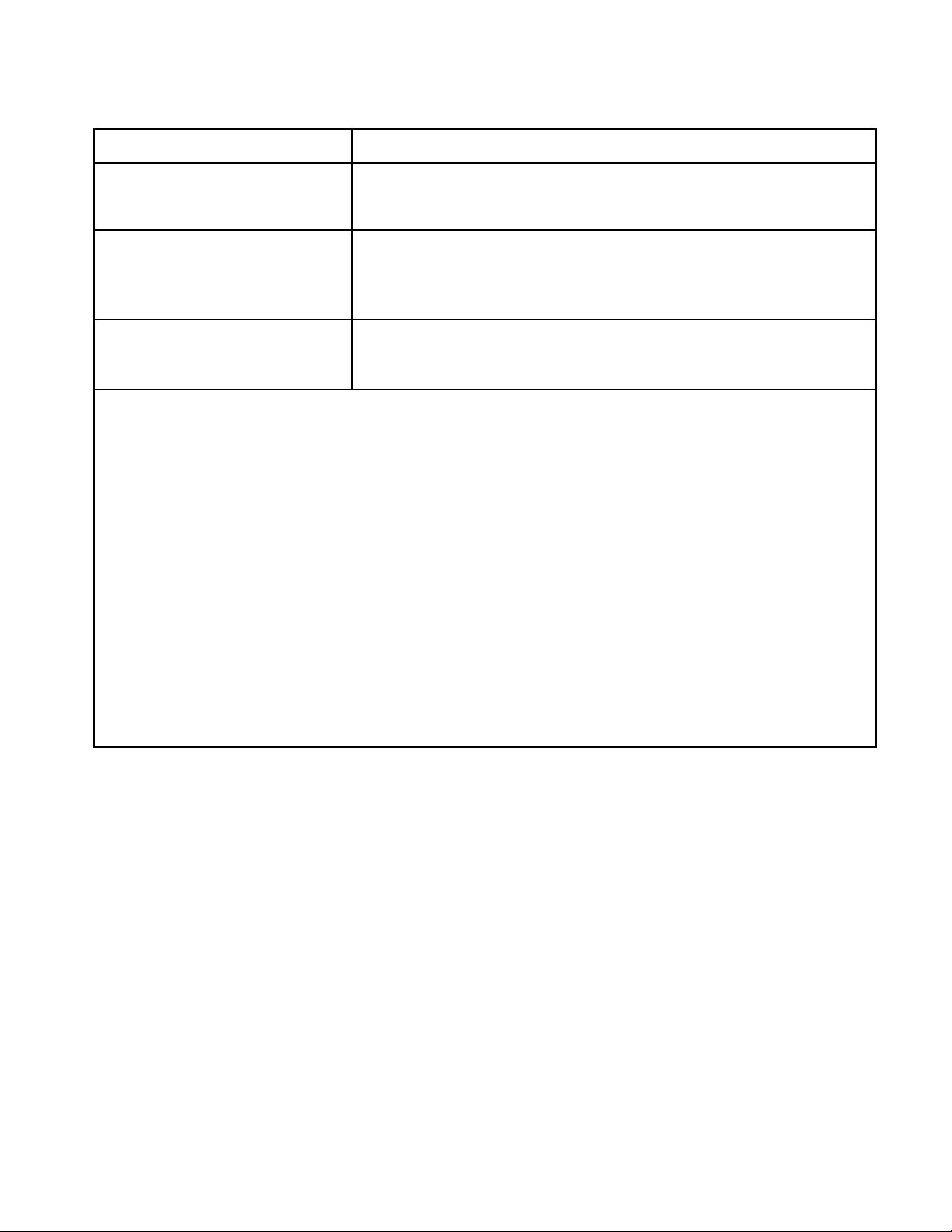
LENGTH OF WARRANTY
FULL ONE YEAR WARRANTY
From Date of Purchase.
SECOND THROUGH FIFTH YEAR
LIMITED WARRANTY
From Date of Purchase.
SECOND THROUGH TENTH
YEAR LIMITED WARRANTY
From Date of Purchase.
KITCHENAID WILL NOT PAY FOR:
A. Service calls to:
1. Correct the installation of the range.
2. Instruct you how to use the range.
3. Replace house fuses or correct house wiring.
B. Repairs when range is used in other than normal, single family household use.
C. Damage resulting from accident, alteration, misuse, abuse, fire, flood, acts of God, improper installation, or
installation not in accordance with local electrical codes.
D. Any labor costs during the limited warranties.
E. Replacement parts or repair labor costs for units operated outside the United States and Canada.
F. Pickup and delivery. Your range is designed to be repaired in the home.
G. Repairs to ceramic glass cooktop if it has not been cared for as recommended in the Use and Care Guide.
H. Repairs to parts or systems resulting from unauthorized modifications made to the appliance.
I. In Canada, travel or transportation expenses to customers who reside in remote areas.
KITCHENAID WILL PAY FOR:
Replacement parts and repair labor costs to correct defects in materials
or workmanship. Service must be provided by a KitchenAid designated
servicing outlet.
Replacement parts for any electric element to correct defects in materials or workmanship. Replacement ceramic glass if breakage is due to
defects in materials or workmanship. Replacement parts for solid state
touch control system to correct defects in materials or workmanship.
Replacement parts for the porcelain oven cavity / inner door if the part
rusts through due to defects in materials or workmanship.
KITCHENAID OR KITCHENAID CANADA DO NOT ASSUME ANY RESPONSIBILITY FOR INCIDENTAL OR
CONSEQUENTIAL DAMAGES. Some states or provinces do not allow the exclusion or limitation of incidental or
consequential damages, so this exclusion or limitation may not apply to you. This warranty gives you special legal
rights, and you may also have other rights which vary from state-to-state or province-to-province.
Outside the United States and Canada, a different warranty may apply. For details, please contact your
authorized KitchenAid dealer.
If you need service first see the “Troubleshooting” section of the Use and Care Guide. After checking ”Troubleshooting,” additional help can be found by checking the “Requesting Assistance or Service” section, or by calling
our Customer Interaction Center telephone numbers, listed below, from anywhere in the U.S.A. or Canada.
KitchenAid: 1-800-422-1230
Canadian Residents call: 1-800-807-6777
1-7

— NOTES —
1-8
INSTALLATION INFORMATION
ELECTRICAL SUPPLY REQUIREMENTS
2. Wire sizes and connections must conform
WARNING
to the requirements of the National Electrical Code, ANSI/NFPA 70—latest edition*,
or CSA Standard C22.1, Canadian Electrical Code, Part 1—latest edition**, and
all local codes and ordinances for the
kilowatt rating of the range.
Electrical Shock Hazard
Electrically ground range.
Failure to do so can result in death, fire, or
electrical shock.
GENERAL
If codes permit, and a separate grounding wire
is used, it is recommended that a qualified
electrician determine that the grounding path is
adequate.
Do not ground to a gas pipe.
Check with a qualified electrician if you are not
sure that the range is grounded.
Do not have a fuse in the neutral or ground
circuit.
1. When a 4-wire or 3-wire, single-phase,
120/240-volt, 60-Hz, AC-only electrical
supply is available, a 50-ampere maximum circuit protection is required, (or, if
specified on the model/serial plate, when
a 4-wire, or 3-wire, single-phase, 120/
208-volt, 60 Hz, AC-only electrical supply
is available, a 40-ampere maximum circuit
protection is required), fused on both sides
of the line. A time-delay fuse, or circuit
breaker is recommended. The model/serial rating plate is located behind the storage drawer (see page 1-4).
Copies of the standards listed may be obtained
from:
* National Fire Protection Association
Batterymarch Park
Quincy, Massachusetts 02269
** CSA International
8501 East Pleasant Valley Road
Cleveland, Ohio 44131-5575
3. This range can be connected directly to
the fused disconnect, or circuit breaker
box, through flexible, armored, or nonmetallic sheathed, copper cable (with ground
wire). Locate the junction box to allow two
to three feet of slack in the line so that the
range can be moved, if servicing is ever
necessary. Do not cut the conduit.
A U.L.-listed conduit connector must be
provided at each end of the power supply
cable, at the range, and at the junction
box. Wire sizes, (copper wire only), and
connections, must conform with the rating
of the range.
2-1
ELECTRICAL CONNECTIONS
(Not used for Canadian
Installations)
This range can be connected directly to the
fused disconnect, or circuit breaker box, through
flexible, armored, or nonmetallic sheathed,
copper cable with a grounding wire. Allow two
to three feet of slack in the line so that it can be
moved if servicing is ever necessary.
A U.L.-listed conduit connector must be provided at each end of the power supply cable at
the range, and at the junction box.
brass
terminal
nuts
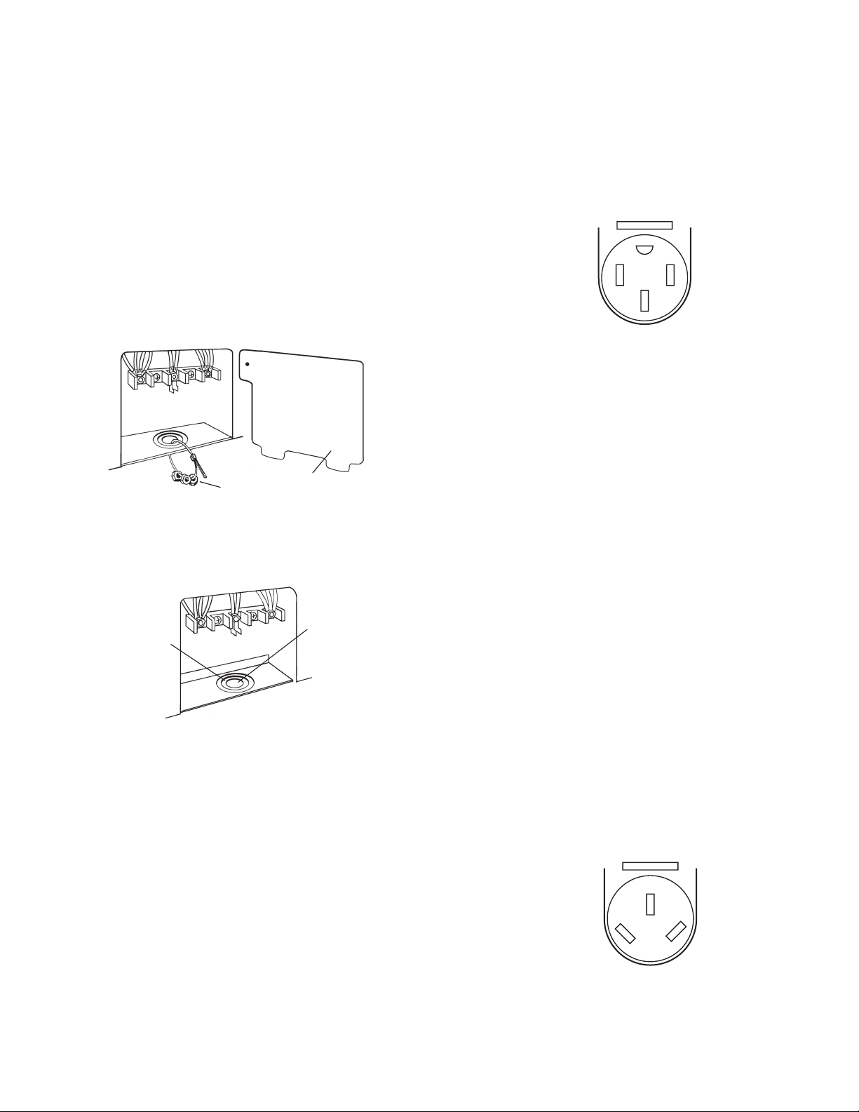
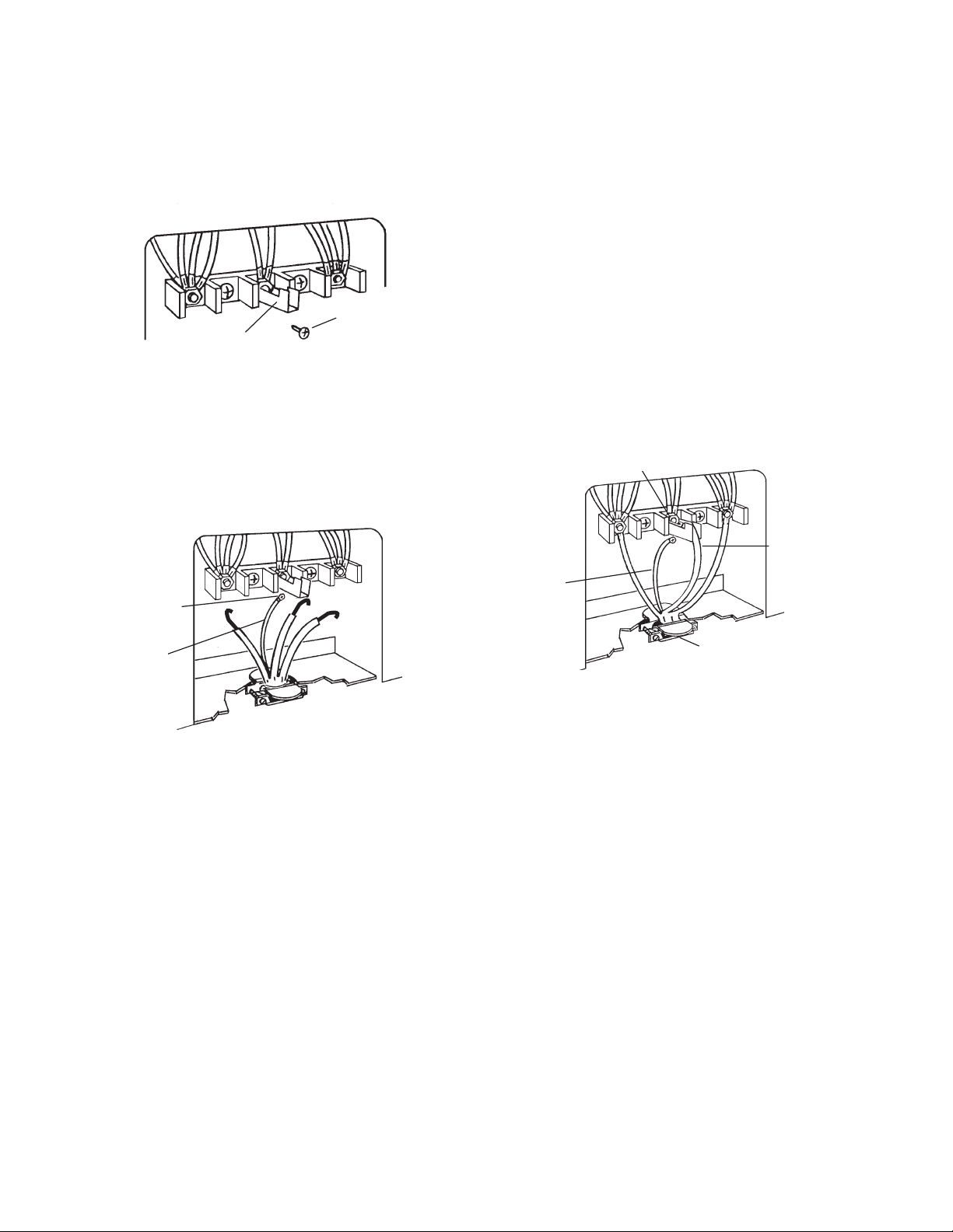
Remove the terminal block cover located on
the back of the range.
terminal
block cover
4-Wire Electrical System
This range is manufactured with the ground
connected to the cabinet. The ground must be
revised so that the green grounding wire of the
4-wire power supply cord is connected to the
cabinet (refer to the “4-wire Electrical Connection” section).
4-Wire
Receptacle
14-50R
When a 4-wire receptacle of NEMA type 1450R is used, a matching U.L.-listed, 4-wire,
250-volt, 40-ampere range power supply cord
(pigtail) must be used.
This cord contains four copper conductors with
ring terminals at the appliance end, terminated
in a NEMA type 14-50P plug on the supply end.
The fourth (grounding) conductor must be identified by a green or green/yellow cover, and the
neutral conductor by a white cover. The cord
should be type SRD, or SRDT, with a U.L.listed strain relief, and be at least four
feet long.
G
XY
W
knockout
opening for
40-ampere
power supply
cord
knockout
opening for
power
supply cable
Depending on the electrical supply, make the
4-wire or the 3-wire connection to the range,
following the instructions under the “Power
Supply Cord Connection,” (page 2-3), or the
“Direct Wire Connection” (page 2-5).
The minimum conductor sizes for the copper
4-wire power cord are:
(2) #8 conductors
(1) #10 white neutral
(1) #8 green grounding
3-Wire Electrical System
Local codes may permit the use of a U.L.listed, 250-volt, 40-ampere range power supply cord (pigtail). This cord contains three # 10
copper wires, and matches a three-wire receptacle of NEMA Type 10-50R.
3-Wire
Receptacle
10-50R
Connectors on the appliance end must be
provided at the point the power supply cord
enters the appliance.
W
XY
2-2
POWER SUPPLY CORD
CONNECTION
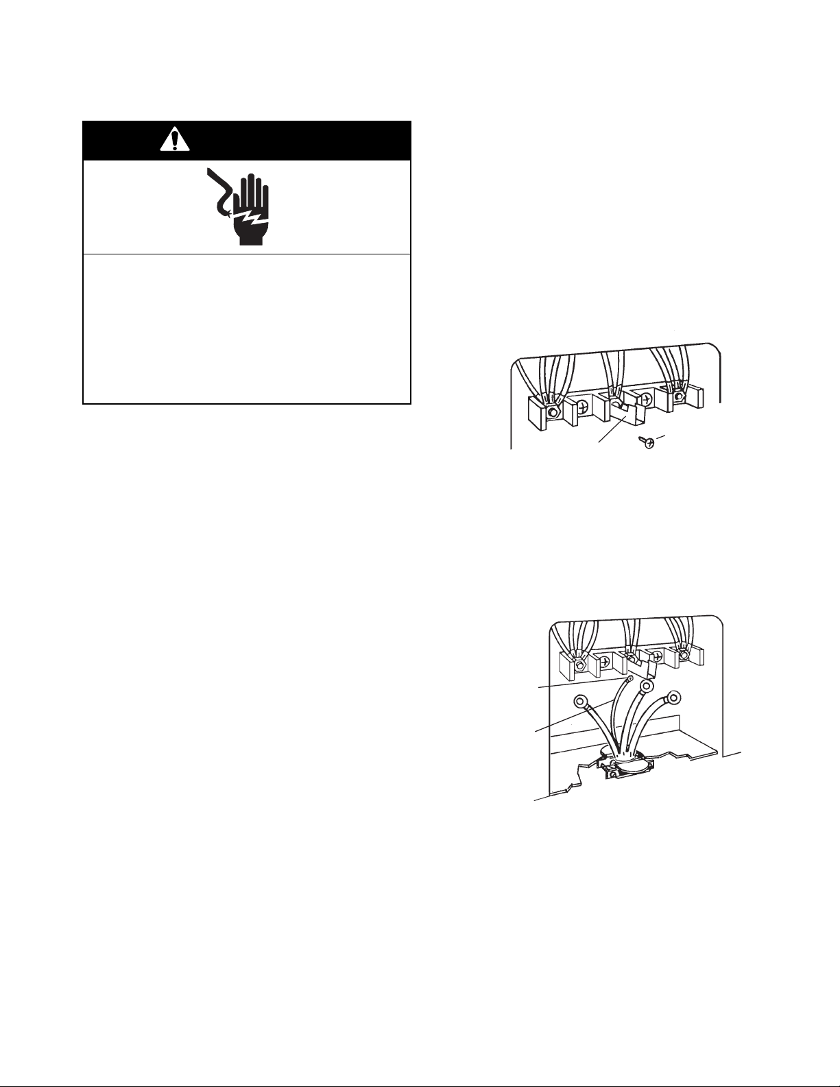
WARNING
Electrical Shock Hazard
7. Depending on the type of electrical system, proceed to “4-Wire Electrical Connection,” or “3-Wire Electrical Connection,” (on page 2-4), and complete the
wiring.
4-Wire Electrical Connection
Use this method for mobile homes, and whenever 4-wire installation is required.
1. Remove the ground-link screw from the
range frame and set the screw aside.
Turn power supply off before connecting
wires.
Electrically ground range.
Failure to do so can result in death, fire, or
electrical shock.
Warning: Improper connection of the equipment-grounding conductor can result in a
risk of electric shock.
Check with a qualified electrician, or serviceman, if you are in doubt as to whether
the appliance is properly grounded.
Do not modify the power supply cord plug.
If it will not fit the outlet, have a proper outlet installed by a qualified electrician.
1. Disconnect the power supply.
2. Remove the screws from the terminal block
cover.
3. Remove the 3/8″ brass nuts that are at-
tached to the knockout opening and set
them aside. Use these brass nuts to secure the ring-type terminals on the power
supply cord to the terminal block screws.
2. Bend the ground link up so that it does not
contact the range.
ground link
3. Connect the green ground wire on the
power supply cord to the ground link screw
hole in the range with the ground-link
screw you removed earlier. Make sure
that the bare ground wire does not contact
the adjacent terminal block connections.
ground-link
screw
green
ground
wire
ground-link
screw
NOTE: Use only ring-type terminals to connect
the power supply cord.
4. Remove the knockout for the 40-ampere
power supply cord.
5. Mount a U.L.-listed strain relief in the knockout opening.
6. Insert the power supply cord through
the strain relief, and allow enough
slack so you can easily attach the wiring to
the terminal block.
2-3
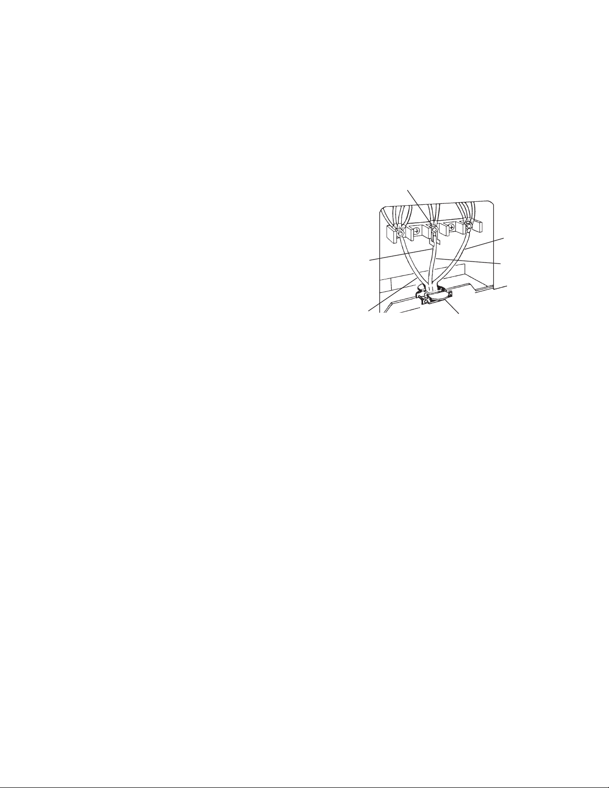
NOTE: Do not loosen the factory-installed
nuts on the terminal block when you perform
the following steps.
4. Connect the neutral (white) wire of the
power supply cord to the center, silvercolored terminal screw on the terminal
block, and secure it with one of the 3/8″
brass nuts that you set aside earlier.
5. Connect the remaining two power supply
cord wires to the outer terminals of the
terminal block, and secure them with 3/8″
brass nuts.
6. Tighten the strain relief screws to secure
the power supply cord.
7. Install the terminal block cover.
silver-colored terminal
block screw
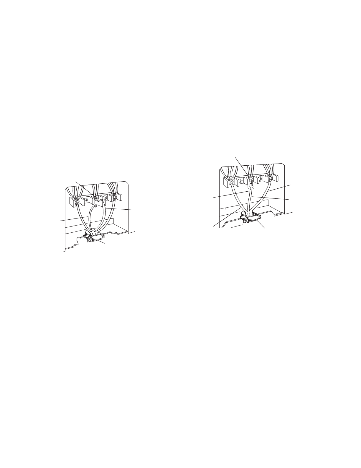
1. Connect the neutral (white) wire of the
power supply cord to the center, silvercolored terminal screw on the terminal
block, and secure it with one of the 3/8″
brass nuts that you set aside earlier.
2. Connect the remaining two power supply
cord wires to the outer terminals of the
terminal block, and secure them with 3/8″
brass nuts.
3. Tighten the strain relief screws to secure
the power supply cord.
4. Install the terminal block cover.
silver-colored terminal
block screw
line 2
neutral wire
(center wire)
green
ground
wire
U.L. listed strain relief
and 40-ampere range
power supply cord
3-Wire Electrical Connection
Use this method only if local codes permit connecting a cabinet-grounded conductor to the
neutral wire of the power supply cord.
NOTE: Do not loosen the factory-installed nuts
on the terminal block when you perform the
following steps.
ground
link
line 1
neutral
(center wire)
U.L.-listed strain relief
and 40-ampere range
power supply cord
2-4
DIRECT WIRE CONNECTION
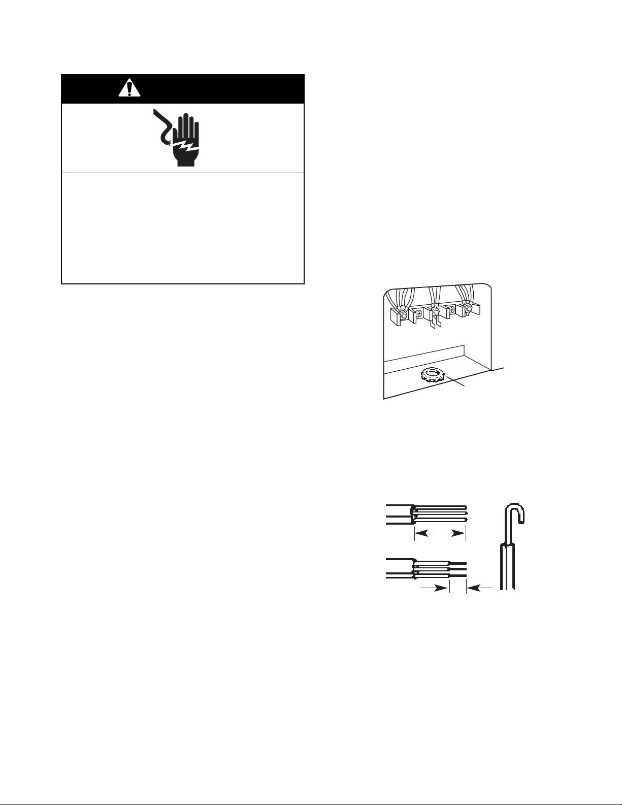
WARNING
4. Disconnect the power supply.
5. Remove the screws from the terminal block
cover.
6. Remove the 3/8″ brass nuts that are at-
tached to the knockout opening and set
them aside. Use these brass nuts to secure the ring-type terminals on the power
supply cord to the terminal block screws.
Electrical Shock Hazard
Turn power supply off before connecting
wires.
Electrically ground range.
Failure to do so can result in death, fire, or
electrical shock.
This range must be connected to a grounded, metallic, permanent wiring system, or a
ground connector should be connected to
the ground terminal, or to the ground wire
lead on the range.
The conductors at the terminal block must
be copper wire only.
If the house has aluminum wiring, perform
steps 1 through 3, otherwise skip those steps.
1. Connect a section of 8-gauge, solid copper wire to the terminal block.
2. Connect the aluminum wiring to the added
section of copper wire using special connectors that were designed by Underwriters Laboratories for joining copper to alu
minum. Follow the procedure recom
mended by the manufacturer to connect
the wires.
NOTE: Use only ring-type terminals to connect
the power supply cord.
7. Remove the knockout for the 40- ampere
power supply cord.
8. Mount a U.L.-listed strain relief in the knockout opening.
U .L.-listed
conduit
connector
9. Strip 3″ of outer covering from the end of
each wire on the power supply cord.
10. Form a hook in the bare wire ends of the
power supply cord.
3"
3. The aluminum-to-copper connections must
conform with local codes and industry
accepted wiring practice.
1"
11. Insert the power supply cord through the
strain relief, and allow enough slack so
you can easily attach the wiring to the
terminal block.
12. Depending on the type of electrical system, proceed to “4-Wire Electrical Connection,” (on page 2-6), or “3-Wire Electrical Connection,” (on page 2-7), and complete the wiring.
2-5
4-Wire Electrical Connection
1. Remove the ground-link screw from the
range frame and set the screw aside.
2. Bend the ground link up so that it does not
contact the range.
ground-link
ground link
screw
NOTE: Do not loosen the factory-installed nuts
on the terminal block when you perform the
following steps.
4. Connect the neutral (white) wire of the
power supply cord to the center, silvercolored terminal screw on the terminal
block, and secure it with one of the 3/8″
brass nuts that you set aside earlier.
5. Connect the remaining two power supply
cord wires to the outer terminals of the
terminal block, and secure them with 3/8″
brass nuts.
3. Connect the green ground wire on the
power supply cord to the ground link screw
hole in the range with the ground-link
screw you removed earlier. Make sure
that the bare ground wire does not contact
the adjacent terminal block connections.
ground-link
screw
bare wire
from power
supply cable
6. Tighten the strain relief screws to secure
the power supply cord.
7. Install the terminal block cover.
silver
-colored terminal
block screw
neutral wire
(white wire)
bare wire
from power
supply cable
U.L. listed conduit
connector and power
supply cable
2-6
3-Wire Electrical Connection
Use this method only if local codes permit connecting a cabinet-grounded conductor to the
neutral wire of the power supply cord.
NOTE: Do not loosen the factory-installed nuts
on the terminal block when you perform the
following steps.
1. Connect the neutral (white) wire of the
power supply cord to the center, silvercolored terminal screw on the terminal
block, and secure it with one of the 3/8″
brass nuts that you set aside earlier.
2. Connect the remaining two power supply
cord wires to the outer terminals of the
terminal block, and secure them with 3/8″
brass nuts.
3. Tighten the strain relief screws to secure
the power supply cord.
4. Install the terminal block cover.
silver-colored terminal
block screw
line 2
ground
link
line 1
neutral wire
(white wire)
U.L. listed conduit
connector and power
supply cable
2-7
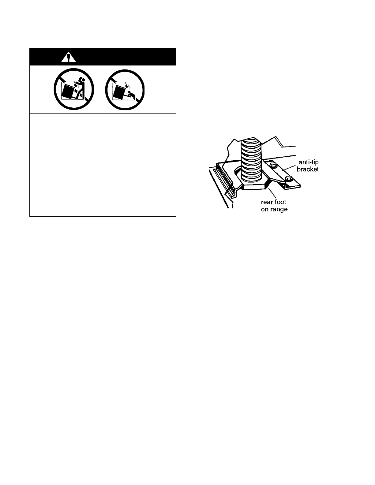
MOVING THE RANGE
WARNING
Tip-Over Hazard
A child or adult can tip the range and
be killed.
Connect anti-tip bracket to rear range
foot.
Reconnect the anti-tip bracket, if the
range is moved.
Failure to follow these instructions can
result in death or serious burns to children and adults.
Before moving the range, slide it onto a piece
of cardboard, or hardboard, to prevent damaging the floor covering, and perform the following steps:
1. Unplug range or disconnect power.
2. Slide the range forward and disengage
the foot with the anti-tip bracket. IMPOR-
TANT: Make sure the anti-tip bracket is
securely attached to floor.
3. Slide range back so the rear foot engages
in the anti-tip bracket.
4. Check to see that the range is level.
5. Reconnect the electrical supply cord.
2-8
THEORY OF OPERATION
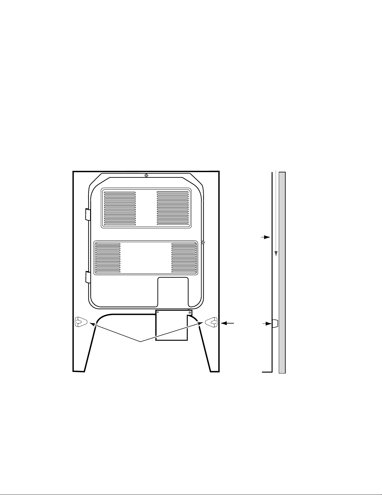
AIR FLOW — REAR PANEL
The electric range needs sufficient air to properly cool the oven. In addition, proper air flow
through the electric range also keeps the front
control panel from becoming too hot while the
elements are operating, and causing operational problems.
To help provide the proper air flow along the
back of the range, the rear panel of the range
has a spacer on each side toward the bottom.
When the range is installed, these spacers
should just come in contact with the surface of
the wall. If they are accidentally bent in, proper
spacing will be lost, and the oven will not heat
properly. Also, the front control panel may become overly warm, and cause the bimetal
switches to trip, shutting down the operation.
If any of these problems occur, it is most likely
because of air flow restrictions.
AIRFLOW
REAR
PANEL
EXTRUDED
SPACERS
ON REAR PANEL
WALL
SPACER
SIDE VIEW
3-1
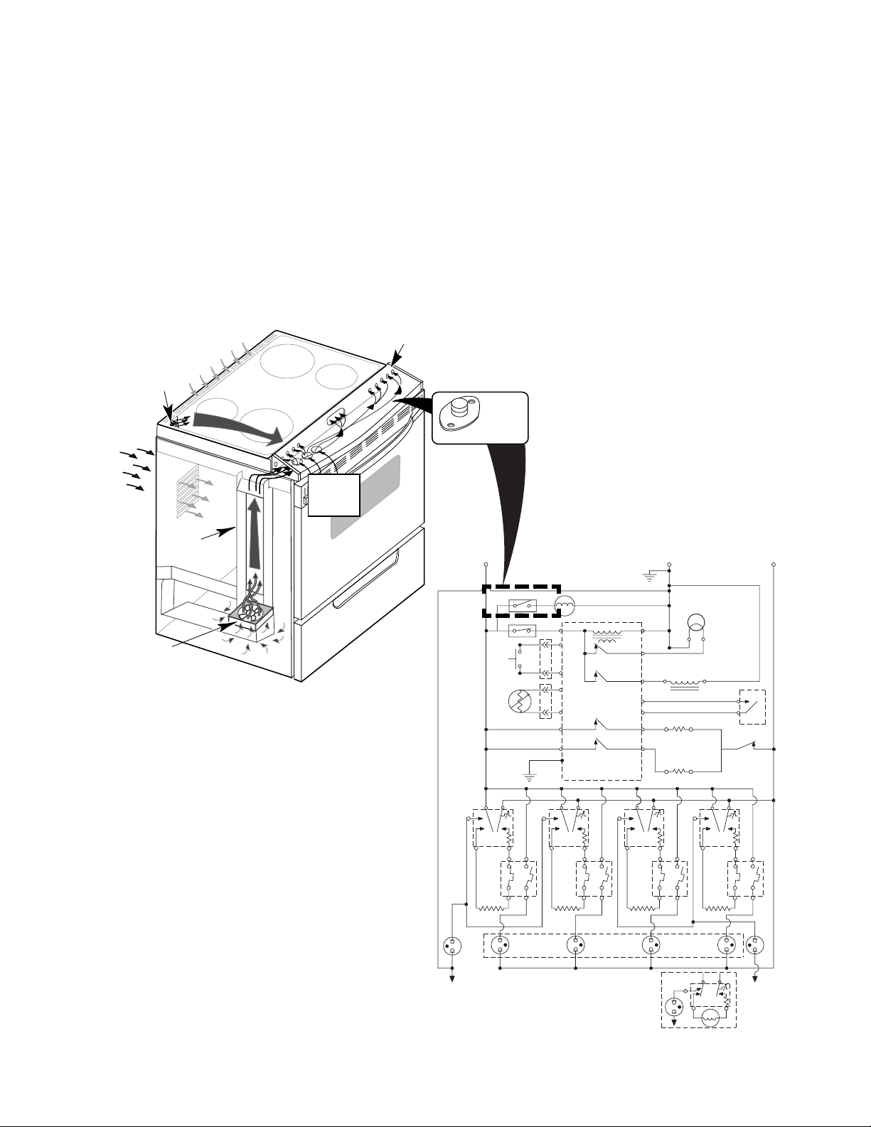
COOLING FAN AIR FLOW
The cooling fan is in series with the cooling
fan bimetal switch, which is located under the
right side of the control panel. When the temperature of the chassis reaches 40˚C (104˚F),
the bimetal switch closes, and turns on the
cooling fan.
The cooling fan draws air from inside the base
of the cabinet. It forces the air up the air channel, which is located under the left side panel,
AIR FLOWS FROM
CONTROL PANEL
UNDER RANGE TOP
OVEN VENT FOR
OVEN EXHAUST
AIR FLOWS
INTO
REAR PANEL
LOUVERS
AIR INLETS
UNDER
CONTROL
PANEL
to the opening at the end of the control panel.
Air then flows across the chassis below the
control panel, and cools it. Air enters through
the series of holes in front of the range top,
flows beneath it, and exits to the outside
through slots in the rear panel. When the control panel chassis temperature drops below
40˚C (104˚F), the bimetal switch opens, and
turns the cooling fan off.
COOLING FAN
BIMETAL SWITCH
COOLING FAN
AIR CHANNEL
DOOR
LATCH SW.
DLB RELAY
V
1B
SURF
IND.
LIGHT
L2
R
R
R
L1
BK
BI - METAL SW FAN N.O.
YY
BI-METAL SW
AMBIENT N.C.
BK
DOOR
SW.
OVEN
TEMP
SENSOR
W
BK
BK
GND
BK
L2L1
P
LF
H1 H2
BK
2ABK2B
1A 1B
V
BU
SURF
IND.
LIGHT
LF
G
P
BK
Y
Y
V
V
H1 H2
Y
M
OVEN CONTROL
P4-3
TRANSFORMER
P3-3
OVEN LIGHT
P3-4
LATCH RELAY
P3-6
P3-7
P2-2
BROIL RELAY
P2-3
OR P6
BAKE RELAY
P3-5
L2L1
LR
2AY2B
1A 1B
LR
RELAY
V
HOT SURFACE
IND. LIGHTS
GND
W
W
DOOR LOCK
SOLENOID
1B
V
P
OVEN LT.
W
BU
R
RR
H1 H2
R
BU
RR
N.O.
COM
L2L1
2ABU2B
1A
P
P4-1
P4-4
P4-5
P3-1
P3-2
P2-1
P2-4
L1
H1 H2
BR
W
R
BR
BU
BU
V
R
RF
2ABR2B
1A
BU
BROIL ELEMENT
BAKE ELEMENT
L2
RF
3-2
N
SUR.
IND.
LIGHT
P
H1
H2
N
N
INF.SWITCH
(OPTIONAL)
COIL ELEMENT
L2
L1
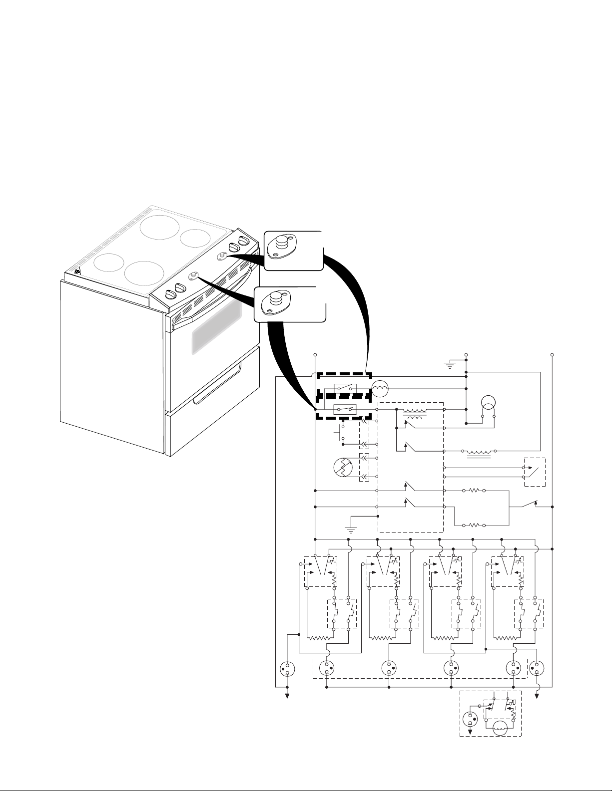
THE BIMETAL SWITCHES
There are two bimetal switches on the electric
range. The switches operate as follows:
• Ambient Bimetal Switch (N.C.)
(Inset #1) —This switch is located under the left side of the control console.
It opens the L1 circuit to the electronic
control board if the console temperature
reaches 96˚C/205˚F.
FAN BIMETAL
AMBIENT
BIMETAL SWITCH
W
Inset #2
COOLING
SWITCH
Inset #1
L1
BK
BI - METAL SW FAN N.O.
DOOR
SW.
OVEN
TEMP
SENSOR
BK
BK
BK
P
LF
• Cooling Fan Bimetal Switch (N.O.)
(Inset #2) —This switch is located un-
der the right side of the control console.
It turns the cooling fan on if the console
temperature reaches 70˚C/158˚F.
GND
YY
BI-METAL SW
AMBIENT N.C.
BK
GND
L2L1
M
P4-3
BK
Y
P3-3
Y
P3-4
V
P3-6
V
P3-7
P2-2
P2-3
OR P6
G
P3-5
P
LR
W
OVEN CONTROL
TRANSFORMER
OVEN LIGHT
RELAY
LATCH RELAY
BROIL RELAY
BAKE RELAY
L2L1
P
P4-1
P4-4
P4-5
P3-1
P3-2
P2-1
P2-4
L1
W
R
BR
BU
BU
BROIL ELEMENT
V
R
L2
RF
W
DOOR LOCK
SOLENOID
BAKE ELEMENT
P
OVEN LT.
W
BU
R
RR
N.O.
COM
L2L1
DOOR
LATCH SW.
DLB RELAY
L2
R
R
R
H1 H2
BK
2ABK2B
1A 1B
V
BU
SURF
IND.
LIGHT
LF
N
H1 H2
Y
2AY2B
1A 1B
V
HOT SURFACE
LR
IND. LIGHTS
H1 H2
BR
BU
2ABR2B
1A
V
RF
SUR.
IND.
LIGHT
H1 H2
R
2ABU2B
1B
1B
P
N
1A
V
BU
RR
L1
H1
H2
L2
SURF
IND.
LIGHT
N
INF. SWITCH
(OPTIONAL)
COIL ELEMENT
3-3
 Loading...