

Page 1
KAC-34
TECHNICAL EDUCATION
SELF-CLEANING
SLIDE-IN ELECTRIC
RANGE
Models KESC300H, KESC307H, KESH307H
JOB AID 4317335
Page 2

FORWARD
This KitchenAid Job Aid, “Self-Cleaning Slide-In Electric Range,” (Part No. 4317335), provides the
technician with information on the installation, operation, and service of the Self-Cleaning SlideIn Electric Range. It is to be used as a training Job Aid and Service Manual. For specific information
on the model being serviced, refer to the “Use and Care Guide,” or “Wiring Diagram” provided with
the electric range.
The Wiring Diagram and Strip Circuits used in this Job Aid are typical and should be used for
training purposes only. Always use the Wiring Diagram supplied with the product when servicing
the unit.
GOALS AND OBJECTIVES
The goal of this Job Aid is to provide detailed information that will enable the service technician to
properly diagnose malfunctions and repair the KitchenAid Self-Cleaning Slide-In Electric Range.
The objectives of this Job Aid are to:
• Understand and follow proper safety precautions.
• Successfully troubleshoot and diagnose malfunctions.
• Successfully perform necessary repairs.
• Successfully return the range to its proper operational status.
WHIRLPOOL CORPORATION assumes no responsibility for any repairs made
on our products by anyone other than Authorized Service Technicians.
Copyright © 2002, Whirlpool Corporation, Benton Harbor, MI 49022
- ii -
Page 3

TABLE OF CONTENTS
Page
GENERAL............................................................................................................................... 1-1
Safety First......................................................................................................................... 1-1
KitchenAid Model & Serial Number Designations.............................................................. 1-3
Model & Serial Number Label Location ............................................................................. 1-4
Specifications..................................................................................................................... 1-5
KitchenAid Electric Range Warranty.................................................................................. 1-7
INSTALLATION INFORMATION ........................................................................................... 2-1
Electrical Supply Requirements ......................................................................................... 2-1
Moving The Range ............................................................................................................ 2-8
THEORY OF OPERATION ..................................................................................................... 3-1
Air Flow—Rear Panel ........................................................................................................ 3-1
Cooling Fan Air Flow ......................................................................................................... 3-2
The Bimetal Switches ........................................................................................................ 3-3
The Surface Element Limiter ............................................................................................. 3-4
The Door Lock Solenoid & Door Latch Switch................................................................... 3-5
How The Self-Clean Cycle Works ..................................................................................... 3-6
COMPONENT ACCESS ......................................................................................................... 4-1
Component Locations ........................................................................................................ 4-1
Removing The Control Panel, An Infinite Switch & Bimetal Switch ................................... 4-2
Removing The Electronic Oven Control And An Indicator Light ........................................ 4-4
Removing An Element & Limiter And The Hot Surface Indicator Assembly ...................... 4-5
Removing The Cooktop Glass ........................................................................................... 4-7
Removing The Door Latch Assembly & The Door Switch ............................................... 4-10
Removing The Dual Broil Element And The Hidden Bake Element ................................ 4-12
Removing The Convection Bake Element & Fan Motor .................................................. 4-14
Removing An Oven Light Socket Assembly .................................................................... 4-16
Removing The Meat Probe Jack ..................................................................................... 4-17
Removing The Oven Temperature Sensor ...................................................................... 4-18
Removing A Side Panel ................................................................................................... 4-19
Removing The Double Line Break (DLB) Relay And The Cooling Fan Motor ................ 4-20
Removing The Oven Door ............................................................................................... 4-22
Removing The Decorative Glass, The Oven Door Handle, The Hinges,
And The Oven Door Glass........................................................................................... 4-23
Removing The Oven Door Gasket................................................................................... 4-25
- iii -
Page 4

Page
COMPONENT TESTING ........................................................................................................ 5-1
Bimetal Switch ................................................................................................................... 5-1
Single Element Infinite Switches........................................................................................ 5-2
Dual Element Infinite Switch (Optional) ............................................................................. 5-3
Surface Elements & Limiters ............................................................................................. 5-4
Door Switch ....................................................................................................................... 5-6
Door Latch Assembly......................................................................................................... 5-6
Hidden Bake Element ........................................................................................................ 5-7
Dual Broil Element ............................................................................................................. 5-7
Convection Bake Element ................................................................................................. 5-8
Convection Fan Motor ....................................................................................................... 5-8
Oven Temperature Sensor ................................................................................................ 5-9
Cooling Fan Motor ............................................................................................................. 5-9
Double Line Break (DLB) Relay....................................................................................... 5-10
DIAGNOSIS & TROUBLESHOOTING ................................................................................... 6-1
Diagnosis ........................................................................................................................... 6-1
Failure / Error Display Codes—Tech Sheet #9753028, Rev. B ..................................... 6-1
Fault Error Code Charts................................................................................................ 6-2
Troubleshooting Charts ..................................................................................................... 6-3
Oven Temperature Calibration .......................................................................................... 6-6
WIRING DIAGRAM & STRIP CIRCUITS ............................................................................... 7-1
Wiring Diagram— #9753028, Rev. B................................................................................. 7-1
Strip Circuits ...................................................................................................................... 7-3
- iv -
Page 5
GENERAL
SAFETY FIRST
Your safety and the safety of others is very important.
We have provided many important safety messages in this Job Aid and on the appliance. Always
read and obey all safety messages.
This is the safety alert symbol.
This symbol alerts you to hazards that can kill or hurt you and others.
All safety messages will follow the safety alert symbol and either the word
“DANGER” or “WARNING.” These words mean:
You can be killed or seriously injured if you don’t
DANGER
WARNING
All safety messages will tell you what the potential hazard is, tell you how to reduce the chance
of injury, and tell you what can happen if the instructions are not followed.
immediately follow instructions.
You can be killed or seriously injured if you don’t
follow instructions.
WARNING
Electrical Shock Hazard
Disconnect power before servicing.
Replace all parts and panels before
operating.
Failure to do so can result in death or
electrical shock.
WARNING
Electrical Shock Hazard
Plug into a grounded 3-prong outlet.
Do not remove ground prong.
Do not use an adapter.
Do not use an extension cord.
Failure to follow these instructions can
result in death, fire, or electrical shock.
1-1
Page 6
WARNING
Electrical Shock Hazard
Electrically ground range.
Failure to do so can result in death, fire, or
electrical shock.
IMPORTANT
Electrostatic Discharge (ESD)
Sensitive Electronics
ESD problems are present everywhere.
ESD may damage or weaken the electronic control assembly. The new control
assembly may appear to work well after
repair is finished, but failure may occur at
a later date due to ESD stress.
• Use an antistatic wrist strap. Connect the
wrist strap to the green ground connection point, or to an unpainted metal surface in the appliance.
WARNING
Tip-Over Hazard
A child or adult can tip the range
and be killed.
Connect anti-tip bracket to rear
range foot.
Reconnect the anti-tip bracket, if the
range is moved.
Failure to follow these instructions
can result in death or serious burns
to children and adults.
- OR -
• Touch your finger repeatedly to a green
ground connection point, or to an unpainted metal surface in the appliance.
• Before removing the part from its package, touch the antistatic bag to a green
ground connection point, or to an unpainted metal surface in the appliance.
• Avoid touching electronic parts, or terminal contacts. Handle the electronic control assembly by the edges only.
• When repackaging the failed electronic
control assembly in an antistatic bag,
observe the previous instructions.
1-2
Page 7

KITCHENAID MODEL & SERIAL NUMBER DESIGNATIONS
MODEL NUMBER
MODEL NUMBER K ES C 30 0 H BL 4
INTERNATIONAL SALES IND.
OR MARKETING CHANNEL
IF PRESENT
PRODUCT GROUP
K = KITCHENAID
PRODUCT IDENTIFICATION
DD = DUAL FUEL DROP-IN / SLIDE-IN
DR = DUAL FUEL RANGE
ED = ELECTRIC DROP-IN RANGE
EE = ELECTRIC EYE-LEVEL RANGE
ER = ELECTRIC STANDARD RANGE
ES = ELECTRIC SLIDE-IN RANGE
GD = GAS DROP-IN RANGE
GE = GAS EYE-LEVEL RANGE
GR = GAS STANDARD RANGE
GS = GAS SLIDE-IN RANGE
MERCHANDISING SCHEME
C = CERAMIC GLASS TOP
H = CERAMIC W/HALOGEN
I = IMPERIAL
P = PROFESSIONAL / COMMERCIAL
S = STANDARD
T = TEMPERED GLASS TOP
CAPACITY / SIZE / SERIES / CONFIGURATION
1ST POSITION 2ND POSITION
1 = DROP-IN 0 = 30″ WIDE
2 = DROP-IN / SLIDE-IN COMBO 6 = 36″ WIDE
3 = SLIDE-IN
4 = COMMERCIAL
5 = STANDARD
7 = EYE-LEVEL
8 = 48″
9 = 60″
FEATURES
0 = STANDARD FEATURES
2 = PLUS FEATURES OR SEALED BURNERS
W / GRILL / CONVECTION OVEN
3 = SEALED BURNERS W / GRIDDLE / CONVECTION OVEN
4 = SEALED BURNERS W / GRILL & GRIDDLE / CONVECTION OVEN
5 = DELUXE FEATURES
7 = DELUXE FEATURES / CONVECTION OR
SEALED BURNERS / CONVECTION OVEN
YEAR OF INTRODUCTION
H = 1999, J = 2000, K= 2001, L - 2002
COLOR CODE
BL = BLACK, WH = WHITE, BT = BISCUIT
BS = BLACK ON STAINLESS
ENGINEERING CHANGE (NUMERIC)
SERIAL NUMBER
SERIAL NUMBER IM K 3 1 73981
MANUFACTURING SITE
IM = MONTMAGNY
YEAR OF PRODUCTION
K = 2000, L = 2001, M = 2002
WEEK OF PRODUCTION
31 = 31ST WEEK
PRODUCT SEQUENCE NUMBER
1-3
Page 8
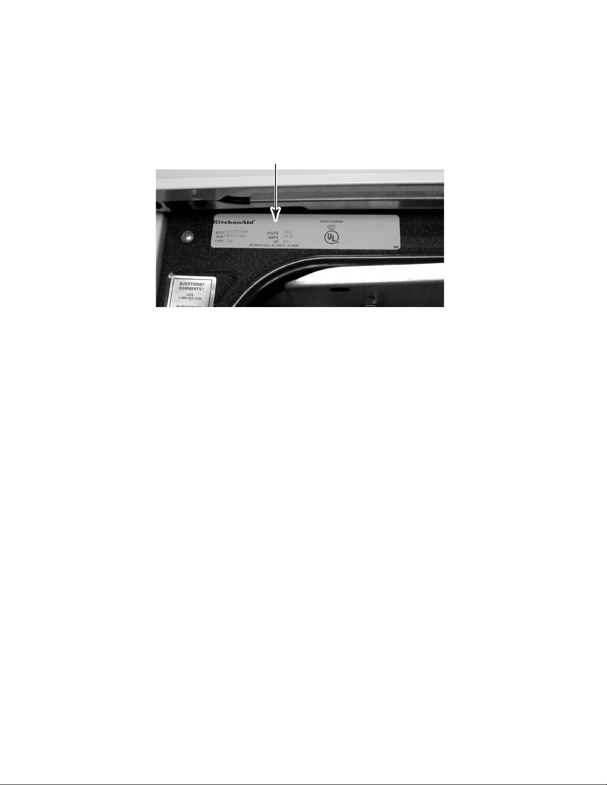
MODEL & SERIAL NUMBER LABEL LOCATION
The Model/Serial Number label location is shown below.
Model & Serial Number Location
(Located Behind Storage Drawer)
1-4
Page 9
SPECIFICATIONS
Model
Model Description
Dimensions/Specifications
Exterior Dimensions
Height To Maintop (in)
Overall Depth Inc Hrdwr/Hndl (in)
Depth Without Handle (in)
Door Swing (in)
Shipping Weight (lbs)
Exterior
Cabinet Finish
Front Frame
Leveling Legs
Oven Window Size and Type
Removable Door and Hinges
Door Liner Finish
Door Type
Control Panel Location
Control Panel Color
Control Panel Construction
Control Knob Type, #, Fcn
Simmer Specialty Switch
Keep Warm Switch
Cooktop Features
Cooktop Material
Hot Surface Indicator
Burner Box Finish
Cooktop Support Rods
Electric Cooktop Element
Electric Element Configuration
Electric Element Type
Electric Right Front Size
Electric RF Output (w@240/208v)
Electric Left Front Size
Electric LF Output (w@240/208v)
Electric Right Rear Size
Electric RR Output (w@240/208v)
Electric Left Rear Size
Electric LR Output (w@240/208v)
Oven Controls
Oven Control Type
Oven Control Location
Control Lock Out
Delayed Cooking Option
Timer
KESC300H WH/BL/BT KESC307H WH/BT/BS KESH307H WH/BL/BS
Slide-In Slide-In Slide-In Radiant/Halogen
36" 36" 36"
26.75" 26.75" 26.75"
24.5" 24.5" 24.5"
21.75" 21.75" 21.75"
160 160 160
Painted Painted Painted
Porcelain Porcelain Porcelain
Yes Yes Yes
Large/Glass Large/Glass Large/Glass
Yes Yes Yes
Porcelain Porcelain Porcelain
Glass Glass Glass
Front Front Front
White White White
Glass Glass Glass
Infinite Switch Single Blade Infinite Switch Single Blade Infinite Switch Single Blade
Yes Yes Yes
Yes Yes Yes
Ceran Top Ceran Top Ceran Top
4 Neon Cluster 4 Neon Cluster 4 Neon Cluster
Galvanized Galvanized Galvanized
No No No
Yes Yes Yes
6", 7", 8", 9.5" 6", 7", 8", 9.5" 6", 7", 8", 9.5"
Radiant Radiant Radiant
7" 7" 7"
1800W 1800W 1800W/Halogen
9.5" 9.5" 9.5"
2500W/1500W 2500W/1500W 2500W/1500W
8" 8" 8"
2200W 2200W 2200W
6" 6" 6"
1500" 1500" 1500"
EOC EOC EOC
Glass Capacitive Glass Capacitive Glass Capacitive
Front Front Front
Yes Yes Yes
Yes Yes Yes
in EOC in EOC in EOC
1-5
Page 10
Model
Interior
Main Oven
Cooking System
Cleaning System
Auto Self Clean Latch
Oven Liner Finish
Oven Volume (cu ft)
Oven Height (in)
Oven Width (in)
Oven Depth (in)
Rack Guides #
Oven Racks #
Oven Rack Type & # Each
Oven Rack
Broiler Pan
Broiler Pan Finish
Broiler Pan Grid Finish
Oven Light Number
Main Electric Oven
Hidden Bake Element
Bake (W@240/208v)
Broil Inner Elem (W@240/208v)
Broil Outer Elem (W@240/208v)
Oven Lower Panel/ Door
Drawer/Panel Front
Storage Drawer Liner
Drawer/Panel Height (in)
Drawer/Panel Width (in)
Drawer/Panel Depth (in)
Glides
Lower Drawer Handle Type/Material
Lower Drawer Handle Color
Product Literature
Cookbook
Installation Instructions
Tech Sheet
Use & Care Guide
Other
Agency Approvals
Anti-tip Device With Unit
KESC300H WH/BL/BT KESC307H WH/BT/BS KESH307H WH/BL/BS
Conventional Fan Convection Fan Convection
Self Cleaning Self Cleaning Self Cleaning
Yes Yes Yes
Porcelain Porcelain Porcelain
3.62 cu ft 3.28 3.28
15.75" 15.75" 15.75"
23 1/16" 23 1/16" 23 1/16"
18.25" 16 5/16" 16 5/16"
55 5
23 3
2 Flat
Yes Yes Yes
Yes Yes Yes
Porcelain Porcelain Porcelain
Porcelain Porcelain Porcelain
1 Incandescent 2 Incandescent 2 Incandescent
Yes Yes Yes
No Yes Yes
2500W
1665W 1665W 1665W
1000W 1000W 1000W
Yes Yes Yes
Painted Painted Painted
Yes Yes Yes
5.1" 5.1" 5.1"
23.3" 23.3" 23.3"
20" 20" 20"
Nylon Rollers Nylon Rollers Nylon Rollers
Formed at Top Formed at Top Formed at Top
White White White
No Yes Yes
9752043 B 9752043 B 9752043 B
9753027 9753027 9753027
Yes Yes Yes
Ceran Polish Incl Ceran Polish Incl Ceran Polish Incl
UL,CSA UL,CSA UL,CSA
Floor Floor Floor
1-6
Page 11
KITCHENAID ELECTRIC RANGE WARRANTY
LENGTH OF WARRANTY
FULL ONE YEAR WARRANTY
From Date of Purchase.
SECOND THROUGH FIFTH YEAR
LIMITED WARRANTY
From Date of Purchase.
SECOND THROUGH TENTH
YEAR LIMITED WARRANTY
From Date of Purchase.
KITCHENAID WILL NOT PAY FOR:
A. Service calls to:
1. Correct the installation of the range.
2. Instruct you how to use the range.
3. Replace house fuses or correct house wiring.
B. Repairs when range is used in other than normal, single family household use.
C. Damage resulting from accident, alteration, misuse, abuse, fire, flood, acts of God, improper installation, or
installation not in accordance with local electrical codes.
D. Any labor costs during the limited warranties.
E. Replacement parts or repair labor costs for units operated outside the United States and Canada.
F. Pickup and delivery. Your range is designed to be repaired in the home.
G. Repairs to ceramic glass cooktop if it has not been cared for as recommended in the Use and Care Guide.
H. Repairs to parts or systems resulting from unauthorized modifications made to the appliance.
I. In Canada, travel or transportation expenses to customers who reside in remote areas.
KITCHENAID WILL PAY FOR:
Replacement parts and repair labor costs to correct defects in materials
or workmanship. Service must be provided by a KitchenAid designated
servicing outlet.
Replacement parts for any electric element to correct defects in materials or workmanship. Replacement ceramic glass if breakage is due to
defects in materials or workmanship. Replacement parts for solid state
touch control system to correct defects in materials or workmanship.
Replacement parts for the porcelain oven cavity / inner door if the part
rusts through due to defects in materials or workmanship.
KITCHENAID OR KITCHENAID CANADA DO NOT ASSUME ANY RESPONSIBILITY FOR INCIDENTAL OR
CONSEQUENTIAL DAMAGES. Some states or provinces do not allow the exclusion or limitation of incidental or
consequential damages, so this exclusion or limitation may not apply to you. This warranty gives you special legal
rights, and you may also have other rights which vary from state-to-state or province-to-province.
Outside the United States and Canada, a different warranty may apply. For details, please contact your
authorized KitchenAid dealer.
If you need service first see the “Troubleshooting” section of the Use and Care Guide. After checking ”Troubleshooting,” additional help can be found by checking the “Requesting Assistance or Service” section, or by calling
our Customer Interaction Center telephone numbers, listed below, from anywhere in the U.S.A. or Canada.
KitchenAid: 1-800-422-1230
Canadian Residents call: 1-800-807-6777
1-7
Page 12

— NOTES —
1-8
Page 13
INSTALLATION INFORMATION
ELECTRICAL SUPPLY REQUIREMENTS
2. Wire sizes and connections must conform
WARNING
to the requirements of the National Electrical Code, ANSI/NFPA 70—latest edition*,
or CSA Standard C22.1, Canadian Electrical Code, Part 1—latest edition**, and
all local codes and ordinances for the
kilowatt rating of the range.
Electrical Shock Hazard
Electrically ground range.
Failure to do so can result in death, fire, or
electrical shock.
GENERAL
If codes permit, and a separate grounding wire
is used, it is recommended that a qualified
electrician determine that the grounding path is
adequate.
Do not ground to a gas pipe.
Check with a qualified electrician if you are not
sure that the range is grounded.
Do not have a fuse in the neutral or ground
circuit.
1. When a 4-wire or 3-wire, single-phase,
120/240-volt, 60-Hz, AC-only electrical
supply is available, a 50-ampere maximum circuit protection is required, (or, if
specified on the model/serial plate, when
a 4-wire, or 3-wire, single-phase, 120/
208-volt, 60 Hz, AC-only electrical supply
is available, a 40-ampere maximum circuit
protection is required), fused on both sides
of the line. A time-delay fuse, or circuit
breaker is recommended. The model/serial rating plate is located behind the storage drawer (see page 1-4).
Copies of the standards listed may be obtained
from:
* National Fire Protection Association
Batterymarch Park
Quincy, Massachusetts 02269
** CSA International
8501 East Pleasant Valley Road
Cleveland, Ohio 44131-5575
3. This range can be connected directly to
the fused disconnect, or circuit breaker
box, through flexible, armored, or nonmetallic sheathed, copper cable (with ground
wire). Locate the junction box to allow two
to three feet of slack in the line so that the
range can be moved, if servicing is ever
necessary. Do not cut the conduit.
A U.L.-listed conduit connector must be
provided at each end of the power supply
cable, at the range, and at the junction
box. Wire sizes, (copper wire only), and
connections, must conform with the rating
of the range.
2-1
Page 14
ELECTRICAL CONNECTIONS
(Not used for Canadian
Installations)
This range can be connected directly to the
fused disconnect, or circuit breaker box, through
flexible, armored, or nonmetallic sheathed,
copper cable with a grounding wire. Allow two
to three feet of slack in the line so that it can be
moved if servicing is ever necessary.
A U.L.-listed conduit connector must be provided at each end of the power supply cable at
the range, and at the junction box.
brass
terminal
nuts
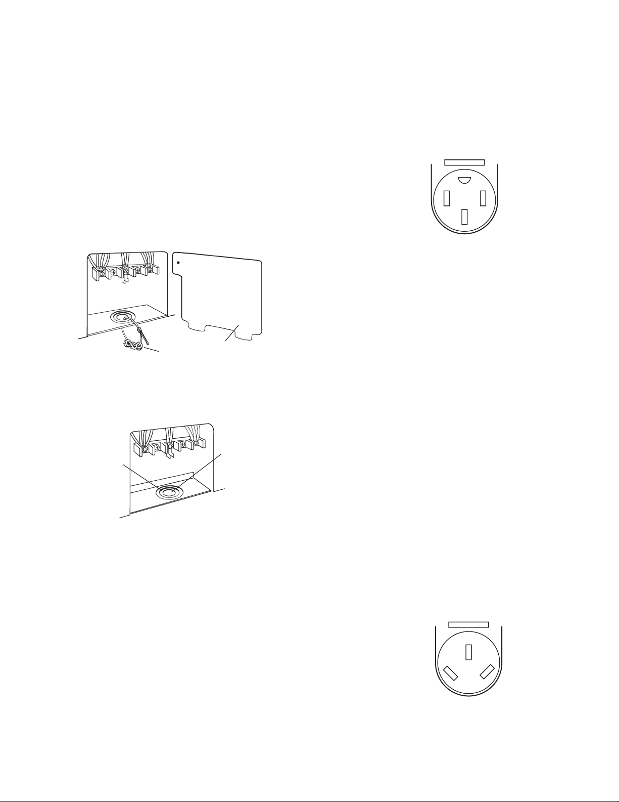
Remove the terminal block cover located on
the back of the range.
terminal
block cover
4-Wire Electrical System
This range is manufactured with the ground
connected to the cabinet. The ground must be
revised so that the green grounding wire of the
4-wire power supply cord is connected to the
cabinet (refer to the “4-wire Electrical Connection” section).
4-Wire
Receptacle
14-50R
When a 4-wire receptacle of NEMA type 1450R is used, a matching U.L.-listed, 4-wire,
250-volt, 40-ampere range power supply cord
(pigtail) must be used.
This cord contains four copper conductors with
ring terminals at the appliance end, terminated
in a NEMA type 14-50P plug on the supply end.
The fourth (grounding) conductor must be identified by a green or green/yellow cover, and the
neutral conductor by a white cover. The cord
should be type SRD, or SRDT, with a U.L.listed strain relief, and be at least four
feet long.
G
XY
W
knockout
opening for
40-ampere
power supply
cord
knockout
opening for
power
supply cable
Depending on the electrical supply, make the
4-wire or the 3-wire connection to the range,
following the instructions under the “Power
Supply Cord Connection,” (page 2-3), or the
“Direct Wire Connection” (page 2-5).
The minimum conductor sizes for the copper
4-wire power cord are:
(2) #8 conductors
(1) #10 white neutral
(1) #8 green grounding
3-Wire Electrical System
Local codes may permit the use of a U.L.listed, 250-volt, 40-ampere range power supply cord (pigtail). This cord contains three # 10
copper wires, and matches a three-wire receptacle of NEMA Type 10-50R.
3-Wire
Receptacle
10-50R
Connectors on the appliance end must be
provided at the point the power supply cord
enters the appliance.
W
XY
2-2
Page 15
POWER SUPPLY CORD
CONNECTION
WARNING
Electrical Shock Hazard
7. Depending on the type of electrical system, proceed to “4-Wire Electrical Connection,” or “3-Wire Electrical Connection,” (on page 2-4), and complete the
wiring.
4-Wire Electrical Connection
Use this method for mobile homes, and whenever 4-wire installation is required.
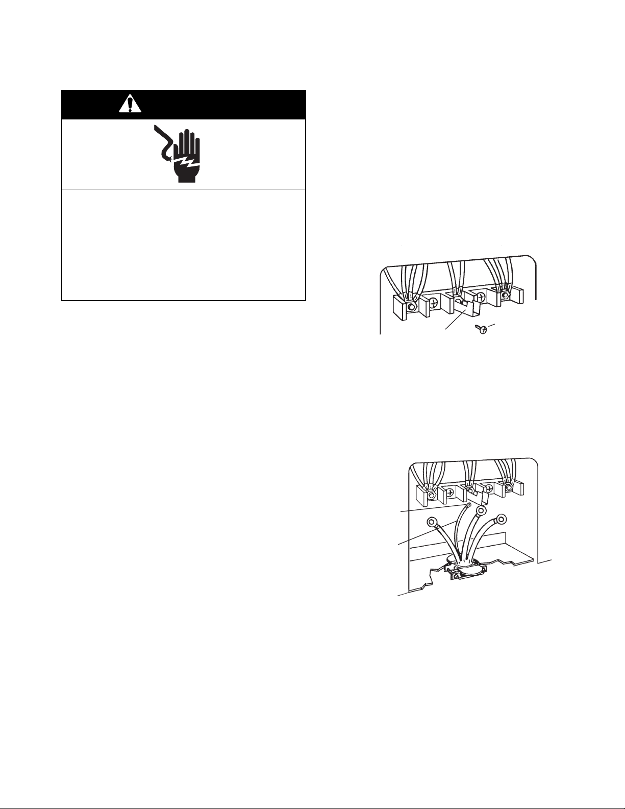
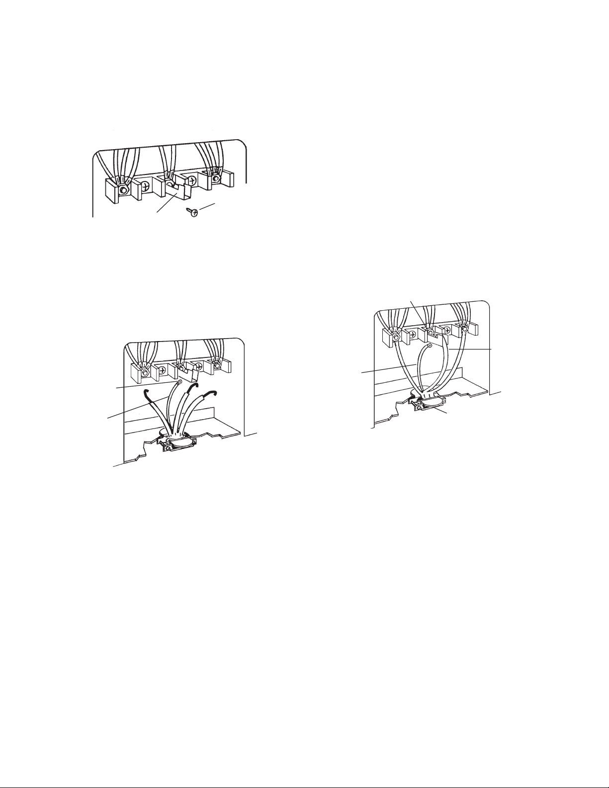
1. Remove the ground-link screw from the
range frame and set the screw aside.
Turn power supply off before connecting
wires.
Electrically ground range.
Failure to do so can result in death, fire, or
electrical shock.
Warning: Improper connection of the equipment-grounding conductor can result in a
risk of electric shock.
Check with a qualified electrician, or serviceman, if you are in doubt as to whether
the appliance is properly grounded.
Do not modify the power supply cord plug.
If it will not fit the outlet, have a proper outlet installed by a qualified electrician.
1. Disconnect the power supply.
2. Remove the screws from the terminal block
cover.
3. Remove the 3/8″ brass nuts that are at-
tached to the knockout opening and set
them aside. Use these brass nuts to secure the ring-type terminals on the power
supply cord to the terminal block screws.
2. Bend the ground link up so that it does not
contact the range.
ground link
3. Connect the green ground wire on the
power supply cord to the ground link screw
hole in the range with the ground-link
screw you removed earlier. Make sure
that the bare ground wire does not contact
the adjacent terminal block connections.
ground-link
screw
green
ground
wire
ground-link
screw
NOTE: Use only ring-type terminals to connect
the power supply cord.
4. Remove the knockout for the 40-ampere
power supply cord.
5. Mount a U.L.-listed strain relief in the knockout opening.
6. Insert the power supply cord through
the strain relief, and allow enough
slack so you can easily attach the wiring to
the terminal block.
2-3
Page 16
NOTE: Do not loosen the factory-installed
nuts on the terminal block when you perform
the following steps.
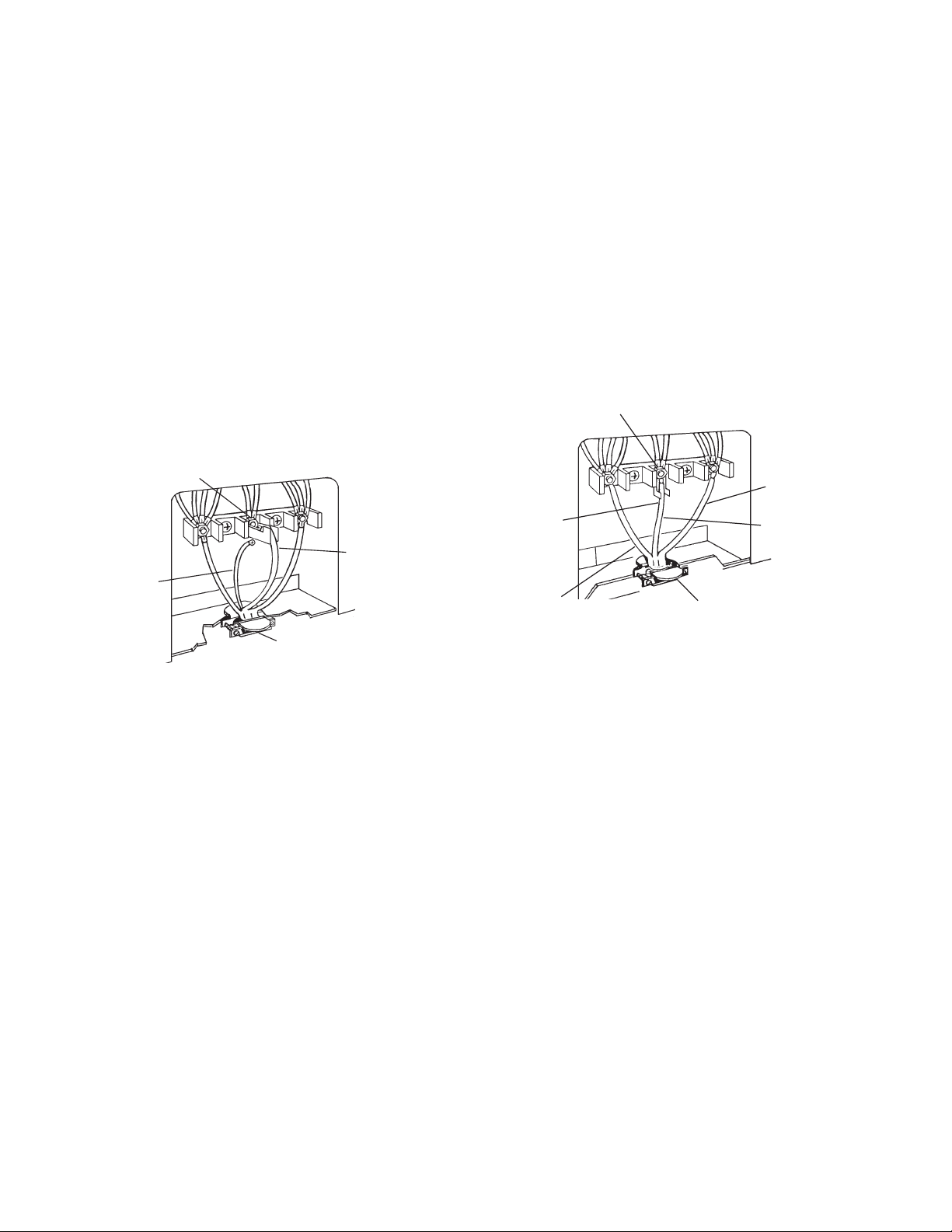
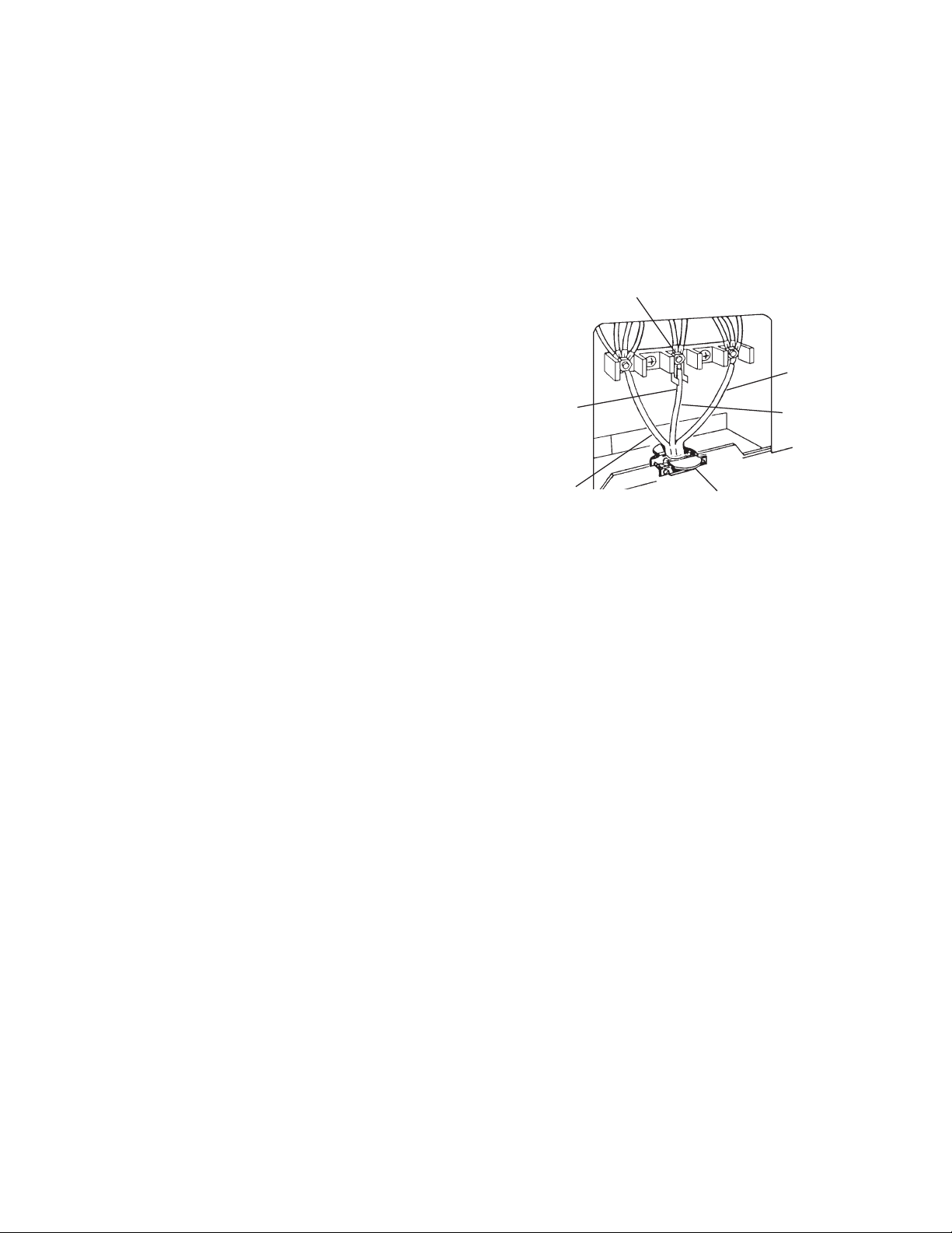
4. Connect the neutral (white) wire of the
power supply cord to the center, silvercolored terminal screw on the terminal
block, and secure it with one of the 3/8″
brass nuts that you set aside earlier.
5. Connect the remaining two power supply
cord wires to the outer terminals of the
terminal block, and secure them with 3/8″
brass nuts.
6. Tighten the strain relief screws to secure
the power supply cord.
7. Install the terminal block cover.
silver-colored terminal
block screw
1. Connect the neutral (white) wire of the
power supply cord to the center, silvercolored terminal screw on the terminal
block, and secure it with one of the 3/8″
brass nuts that you set aside earlier.
2. Connect the remaining two power supply
cord wires to the outer terminals of the
terminal block, and secure them with 3/8″
brass nuts.
3. Tighten the strain relief screws to secure
the power supply cord.
4. Install the terminal block cover.
silver-colored terminal
block screw
line 2
neutral wire
(center wire)
green
ground
wire
U.L. listed strain relief
and 40-ampere range
power supply cord
3-Wire Electrical Connection
Use this method only if local codes permit connecting a cabinet-grounded conductor to the
neutral wire of the power supply cord.
NOTE: Do not loosen the factory-installed nuts
on the terminal block when you perform the
following steps.
ground
link
line 1
neutral
(center wire)
U.L.-listed strain relief
and 40-ampere range
power supply cord
2-4
Page 17
DIRECT WIRE CONNECTION
WARNING
4. Disconnect the power supply.
5. Remove the screws from the terminal block
cover.
6. Remove the 3/8″ brass nuts that are at-
tached to the knockout opening and set
them aside. Use these brass nuts to secure the ring-type terminals on the power
supply cord to the terminal block screws.
Electrical Shock Hazard
Turn power supply off before connecting
wires.
Electrically ground range.
Failure to do so can result in death, fire, or
electrical shock.
This range must be connected to a grounded, metallic, permanent wiring system, or a
ground connector should be connected to
the ground terminal, or to the ground wire
lead on the range.
The conductors at the terminal block must
be copper wire only.
If the house has aluminum wiring, perform
steps 1 through 3, otherwise skip those steps.
1. Connect a section of 8-gauge, solid copper wire to the terminal block.
2. Connect the aluminum wiring to the added
section of copper wire using special connectors that were designed by Underwriters Laboratories for joining copper to alu
minum. Follow the procedure recom
mended by the manufacturer to connect
the wires.
NOTE: Use only ring-type terminals to connect
the power supply cord.
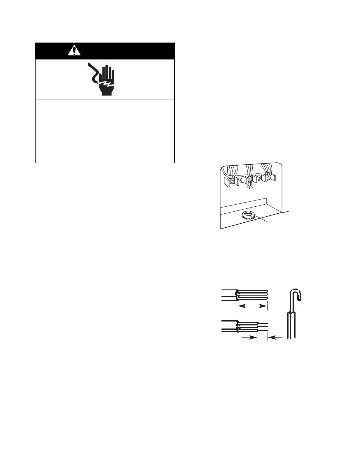
7. Remove the knockout for the 40- ampere
power supply cord.
8. Mount a U.L.-listed strain relief in the knockout opening.
U .L.-listed
conduit
connector
9. Strip 3″ of outer covering from the end of
each wire on the power supply cord.
10. Form a hook in the bare wire ends of the
power supply cord.
3"
3. The aluminum-to-copper connections must
conform with local codes and industry
accepted wiring practice.
1"
11. Insert the power supply cord through the
strain relief, and allow enough slack so
you can easily attach the wiring to the
terminal block.
12. Depending on the type of electrical system, proceed to “4-Wire Electrical Connection,” (on page 2-6), or “3-Wire Electrical Connection,” (on page 2-7), and complete the wiring.
2-5
Page 18
4-Wire Electrical Connection
1. Remove the ground-link screw from the
range frame and set the screw aside.
2. Bend the ground link up so that it does not
contact the range.
ground-link
ground link
screw
NOTE: Do not loosen the factory-installed nuts
on the terminal block when you perform the
following steps.
4. Connect the neutral (white) wire of the
power supply cord to the center, silvercolored terminal screw on the terminal
block, and secure it with one of the 3/8″
brass nuts that you set aside earlier.
5. Connect the remaining two power supply
cord wires to the outer terminals of the
terminal block, and secure them with 3/8″
brass nuts.
3. Connect the green ground wire on the
power supply cord to the ground link screw
hole in the range with the ground-link
screw you removed earlier. Make sure
that the bare ground wire does not contact
the adjacent terminal block connections.
ground-link
screw
bare wire
from power
supply cable
6. Tighten the strain relief screws to secure
the power supply cord.
7. Install the terminal block cover.
silver
-colored terminal
block screw
neutral wire
(white wire)
bare wire
from power
supply cable
U.L. listed conduit
connector and power
supply cable
2-6
Page 19
3-Wire Electrical Connection
Use this method only if local codes permit connecting a cabinet-grounded conductor to the
neutral wire of the power supply cord.
NOTE: Do not loosen the factory-installed nuts
on the terminal block when you perform the
following steps.
1. Connect the neutral (white) wire of the
power supply cord to the center, silvercolored terminal screw on the terminal
block, and secure it with one of the 3/8″
brass nuts that you set aside earlier.
2. Connect the remaining two power supply
cord wires to the outer terminals of the
terminal block, and secure them with 3/8″
brass nuts.
3. Tighten the strain relief screws to secure
the power supply cord.
4. Install the terminal block cover.
silver-colored terminal
block screw
line 2
ground
link
line 1
neutral wire
(white wire)
U.L. listed conduit
connector and power
supply cable
2-7
Page 20
MOVING THE RANGE
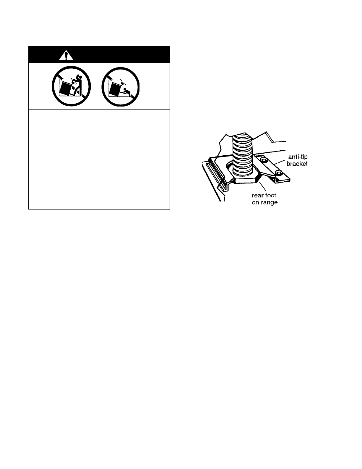
WARNING
Tip-Over Hazard
A child or adult can tip the range and
be killed.
Connect anti-tip bracket to rear range
foot.
Reconnect the anti-tip bracket, if the
range is moved.
Failure to follow these instructions can
result in death or serious burns to children and adults.
Before moving the range, slide it onto a piece
of cardboard, or hardboard, to prevent damaging the floor covering, and perform the following steps:
1. Unplug range or disconnect power.
2. Slide the range forward and disengage
the foot with the anti-tip bracket. IMPOR-
TANT: Make sure the anti-tip bracket is
securely attached to floor.
3. Slide range back so the rear foot engages
in the anti-tip bracket.
4. Check to see that the range is level.
5. Reconnect the electrical supply cord.
2-8
Page 21
THEORY OF OPERATION
AIR FLOW — REAR PANEL
The electric range needs sufficient air to properly cool the oven. In addition, proper air flow
through the electric range also keeps the front
control panel from becoming too hot while the
elements are operating, and causing operational problems.
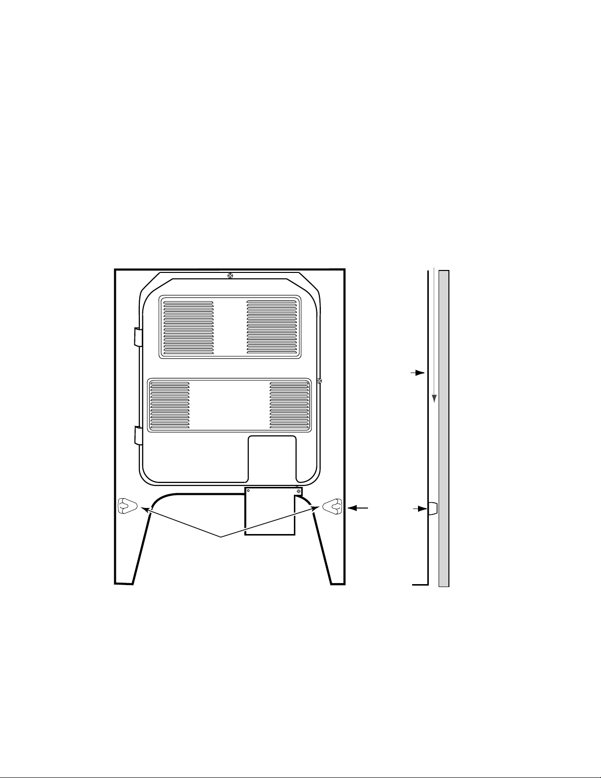
To help provide the proper air flow along the
back of the range, the rear panel of the range
has a spacer on each side toward the bottom.
When the range is installed, these spacers
should just come in contact with the surface of
the wall. If they are accidentally bent in, proper
spacing will be lost, and the oven will not heat
properly. Also, the front control panel may become overly warm, and cause the bimetal
switches to trip, shutting down the operation.
If any of these problems occur, it is most likely
because of air flow restrictions.
AIRFLOW
REAR
PANEL
EXTRUDED
SPACERS
ON REAR PANEL
WALL
SPACER
SIDE VIEW
3-1
Page 22
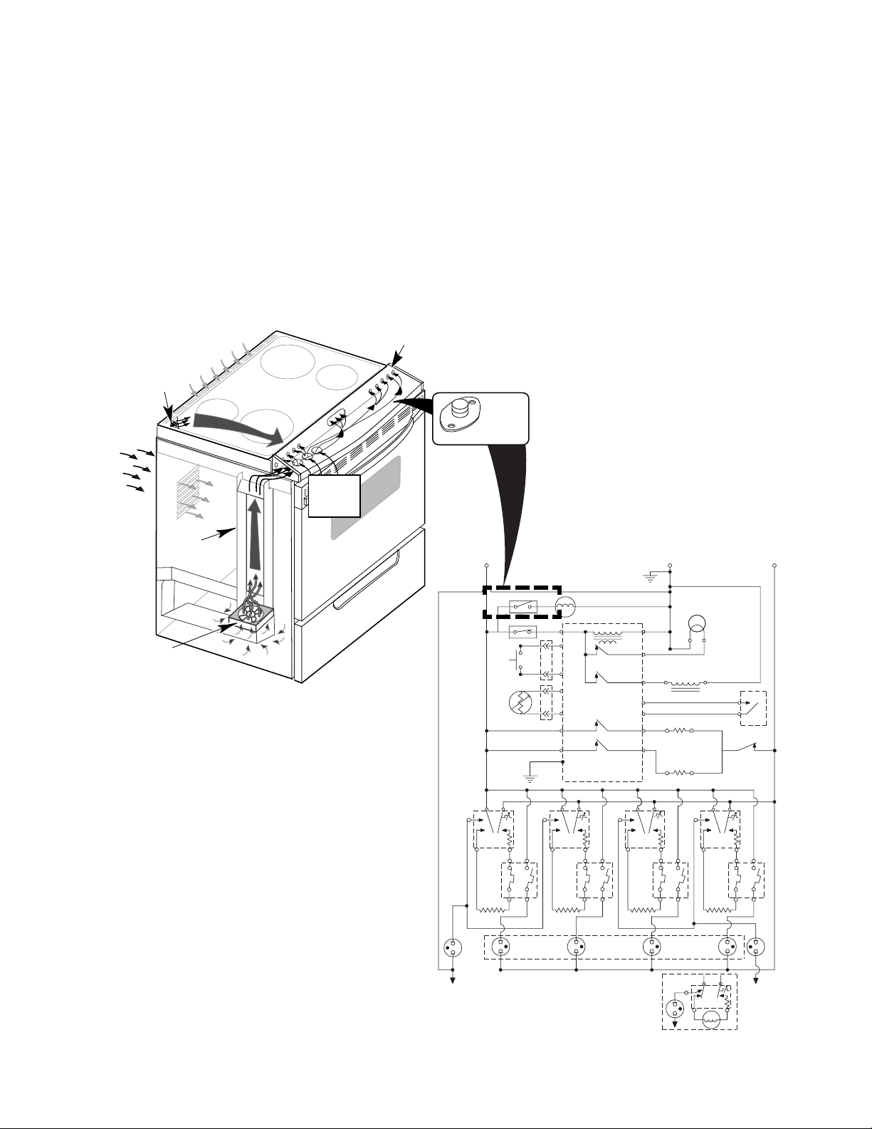
COOLING FAN AIR FLOW
The cooling fan is in series with the cooling
fan bimetal switch, which is located under the
right side of the control panel. When the temperature of the chassis reaches 40˚C (104˚F),
the bimetal switch closes, and turns on the
cooling fan.
The cooling fan draws air from inside the base
of the cabinet. It forces the air up the air channel, which is located under the left side panel,
AIR FLOWS FROM
CONTROL PANEL
UNDER RANGE TOP
OVEN VENT FOR
OVEN EXHAUST
AIR FLOWS
INTO
REAR PANEL
LOUVERS
AIR INLETS
UNDER
CONTROL
PANEL
to the opening at the end of the control panel.
Air then flows across the chassis below the
control panel, and cools it. Air enters through
the series of holes in front of the range top,
flows beneath it, and exits to the outside
through slots in the rear panel. When the control panel chassis temperature drops below
40˚C (104˚F), the bimetal switch opens, and
turns the cooling fan off.
COOLING FAN
BIMETAL SWITCH
COOLING FAN
AIR CHANNEL
DOOR
LATCH SW.
DLB RELAY
V
1B
SURF
IND.
LIGHT
L2
R
R
R
L1
BK
BI - METAL SW FAN N.O.
YY
BI-METAL SW
AMBIENT N.C.
BK
DOOR
SW.
OVEN
TEMP
SENSOR
W
BK
BK
GND
BK
L2L1
P
LF
H1 H2
BK
2ABK2B
1A 1B
V
BU
SURF
IND.
LIGHT
LF
G
P
BK
Y
Y
V
V
H1 H2
Y
M
OVEN CONTROL
P4-3
TRANSFORMER
P3-3
OVEN LIGHT
P3-4
LATCH RELAY
P3-6
P3-7
P2-2
BROIL RELAY
P2-3
OR P6
BAKE RELAY
P3-5
L2L1
LR
2AY2B
1A 1B
LR
RELAY
V
HOT SURFACE
IND. LIGHTS
GND
W
W
DOOR LOCK
SOLENOID
1B
V
P
OVEN LT.
W
BU
R
RR
H1 H2
R
BU
RR
N.O.
COM
L2L1
2ABU2B
1A
P
P4-1
P4-4
P4-5
P3-1
P3-2
P2-1
P2-4
L1
H1 H2
BR
W
R
BR
BU
BU
V
R
RF
2ABR2B
1A
BU
BROIL ELEMENT
BAKE ELEMENT
L2
RF
3-2
N
SUR.
IND.
LIGHT
P
H1
H2
N
N
INF.SWITCH
(OPTIONAL)
COIL ELEMENT
L2
L1
Page 23
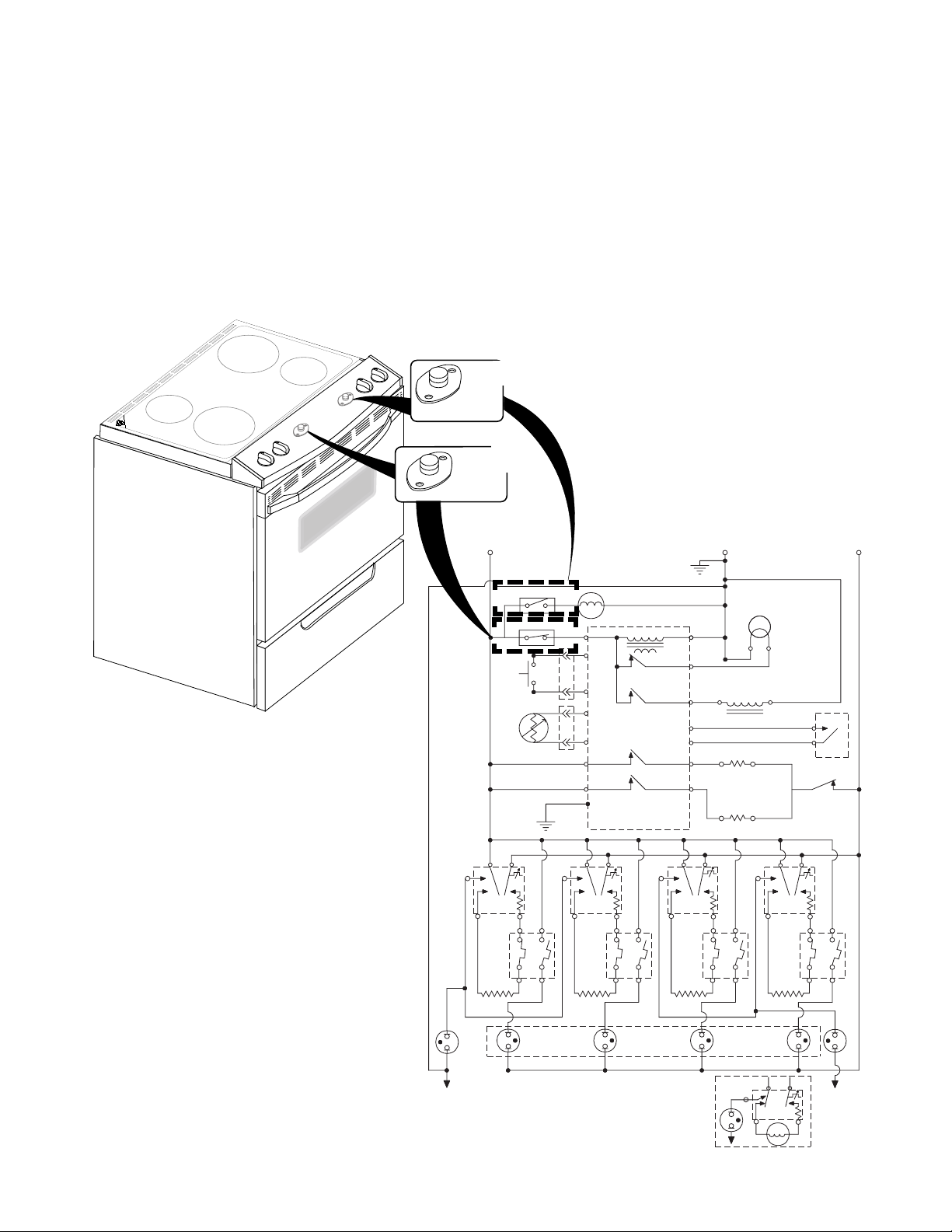
THE BIMETAL SWITCHES
There are two bimetal switches on the electric
range. The switches operate as follows:
• Ambient Bimetal Switch (N.C.)
(Inset #1) —This switch is located under the left side of the control console.
It opens the L1 circuit to the electronic
control board if the console temperature
reaches 96˚C/205˚F.
FAN BIMETAL
AMBIENT
BIMETAL SWITCH
W
Inset #2
COOLING
SWITCH
Inset #1
L1
BK
BI - METAL SW FAN N.O.
DOOR
SW.
OVEN
TEMP
SENSOR
BK
BK
BK
P
LF
• Cooling Fan Bimetal Switch (N.O.)
(Inset #2) —This switch is located un-
der the right side of the control console.
It turns the cooling fan on if the console
temperature reaches 70˚C/158˚F.
GND
YY
BI-METAL SW
AMBIENT N.C.
BK
GND
L2L1
M
P4-3
BK
Y
P3-3
Y
P3-4
V
P3-6
V
P3-7
P2-2
P2-3
OR P6
G
P3-5
P
LR
W
OVEN CONTROL
TRANSFORMER
OVEN LIGHT
RELAY
LATCH RELAY
BROIL RELAY
BAKE RELAY
L2L1
P
P4-1
P4-4
P4-5
P3-1
P3-2
P2-1
P2-4
L1
W
R
BR
BU
BU
BROIL ELEMENT
V
R
L2
RF
W
DOOR LOCK
SOLENOID
BAKE ELEMENT
P
OVEN LT.
W
BU
R
RR
N.O.
COM
L2L1
DOOR
LATCH SW.
DLB RELAY
L2
R
R
R
H1 H2
BK
2ABK2B
1A 1B
V
BU
SURF
IND.
LIGHT
LF
N
H1 H2
Y
2AY2B
1A 1B
V
HOT SURFACE
LR
IND. LIGHTS
H1 H2
BR
BU
2ABR2B
1A
V
RF
SUR.
IND.
LIGHT
H1 H2
R
2ABU2B
1B
1B
P
N
1A
V
BU
RR
L1
H1
H2
L2
SURF
IND.
LIGHT
N
INF. SWITCH
(OPTIONAL)
COIL ELEMENT
3-3
Page 24

THE SURFACE ELEMENT LIMITER
The surface element limiter is a safety device
that is mounted in the surface element circuit .
MAINTOP SENSING ROD HEATING COIL
INSULATION LIMITER
ELEMENT
TERMINALS
LIMITER
TERMINALS
L1
BK
BI - METAL SW FAN N.O.
YY
BI-METAL SW
AMBIENT N.C.
BK
DOOR
SW.
OVEN
TEMP
SENSOR
W
BK
BK
GND
BK
P
L2L1
LF
M
OVEN CONTROL
P4-3
Y
Y
V
V
P3-3
P3-4
P3-6
P3-7
P2-2
P2-3
OR P6
P3-5
LR
TRANSFORMER
OVEN LIGHT
RELAY
LATCH RELAY
BROIL RELAY
BAKE RELAY
L2L1
BK
G
P
GND
W
W
P4-1
R
P4-4
DOOR LOCK
BR
BU
BU
BROIL ELEMENT
V
R
L2
RF
SOLENOID
BAKE ELEMENT
P4-5
P3-1
P3-2
P2-1
P2-4
L1
P
The limiter monitors the temperature of the
cooktop glass in two ways:
a)Circuit 1A to 2A, which is a normally-
closed (N.C.) switch, opens at 1025˚F
and protects the ceran glass from heat
damage.
b)Circuit 1B to 2B, which is a normally-
open switch (N.O.) switch, closes and
turns on the hot surface indicator lights
if the temperature of the cooktop is
greater than 150˚F. This switch will remain closed until the ceran glass is
warm enough to touch.
2A 2B
1A
1B
L2
R
OVEN LT.
W
W
N.O.
COM
BU
P
DOOR
LATCH SW.
R
DLB RELAY
R
L2L1
RR
R
2A 2B
1A
1B
H1 H2
BK
2ABK2B
1A 1B
V
BU
SURF
N
IND.
LIGHT
LF
H1 H2
Y
2AY2B
1A 1B
V
HOT SURFACE
LR
IND. LIGHTS
H1 H2
BR
BU
2ABR2B
1A
V
RF
SUR.
IND.
LIGHT
H1 H2
R
2ABU2B
1B
1B
P
N
1A
V
BU
RR
L1
H1
H2
L2
SURF
IND.
LIGHT
N
INF.SWITCH
(OPTIONAL)
COIL ELEMENT
3-4
Page 25

THE DOOR LOCK SOLENOID & DOOR LATCH SWITCH
The door lock solenoid operates on a 120-volt
pulse from the electronic control board. When
the door is in the unlocked position, the plunger
is extended. When the door latch switch is
open, the control senses that the door is unlocked. When the door latch switch closes, the
control senses that the door is locked. The door
latch switch, mounted on the solenoid bracket,
is in the N.O. (normally-open) position. During
DOOR
UNLOCKED
LATCH
ACTUATOR
ROD
DOOR LATCH
SWITCH OPEN
The Door Lock Solenoid
(Door Unlocked)
the self-clean cycle, the control board sends a
120-volt pulse to the solenoid windings, which
pulls the plunger in, and moves the latch actuator rod to lock the oven door. The movement of the rod also actuates the door latch
switch and closes it. When the self-clean cycle
is over, the control board sends a 120-volt pulse
to the solenoid, the plunger is pushed out, the
latch actuator rod releases the door, and the
door latch switch opens.
DOOR UNLOCKED
DOOR
LOCKED
LATCH
ACTUATOR
ROD
The Door Lock Solenoid
(Door Locked)
PLUNGER OUT
DOOR LATCH
SWITCH CLOSED
PLUNGER IN
DOOR LOCKED
SOLENOID
120 VAC
SOLENOID
120 VAC
DOOR
LATCH SW.
DLB RELAY
1B
V
SURF
IND.
LIGHT
N
INF.SWITCH
(OPTIONAL)
COIL ELEMENT
L2
R
R
R
L1
BK
BI - METAL SW FAN N.O.
YY
BI-METALSW
AMBIENT N.C.
BK
DOOR
SW.
OVEN
TEMP
SENSOR
W
BK
BK
GND
BK
L2L1
P
LF
H1 H2
BK
2ABK2B
1A 1B
BU
SURF
IND.
LIGHT
N
V
LF
M
OVEN CONTROL
P4-3
TRANSFORMER
BK
Y
P3-3
OVEN LIGHT
RELAY
Y
P3-4
V
LATCH RELAY
P3-6
V
P3-7
P2-2
BROIL RELAY
P2-3
OR P6
P3-5
LR
H1 H2
Y
BAKE RELAY
L2L1
2AY2B
1A 1B
V
HOT SURFACE
LR
IND.LIGHTS
G
P
GND
W
W
DOOR LOCK
SOLENOID
1B
V
SUR.
IND.
P
N
P
L1
H1
OVEN LT.
W
BU
R
H1 H2
R
BU
RR
N.O.
COM
RR
2ABU2B
1A
L2
H2
L2L1
P
P4-1
P4-4
P4-5
P3-1
P3-2
P2-1
P2-4
L1
H1 H2
BR
W
R
BR
BU
BU
V
R
RF
2ABR2B
1A
BU
BROIL ELEMENT
BAKE ELEMENT
L2
RF
LIGHT
3-5
Page 26

HOW THE SELF-CLEAN CYCLE WORKS
The Self-Clean cycle uses high heat to burn
away soil and grease from inside the oven.
During this cycle, the oven will get much hotter than it does under normal baking and broiling conditions (see the following chart).
AFTER 30 MINUTES OF CLEAN
L1
The oven is preset for a 3-1/2 hour Self-Clean
cycle. However, you can adjust this cycle time
to between 2-1/2 and 4-1/2 hours. The chart
shows a normal 3-1/2 hour Self-Clean cycle.
Note that although the heating turns off after
3 hours, the door will remain locked for an additional 1/2 hour so the oven can cool sufficiently.
During the Self-Clean cycle, the bake element
is on all the time. If the door latch switch is not
activated during the clean operation, the cycle
is terminated and the display will show “close
door.”
L2
MICROCOMPUTER
BAKE
ELEMENT
P2-4P2-3
DLB
RELAY
3-6
Page 27

COMPONENT ACCESS
This section instructs you on how to service each component inside the range. The range
components and their locations are shown below.
COMPONENT LOCATIONS
Indicator Light
Single Element
Infinite Switch
Dual Element
Infinite Switch
Oven Light
Meat Probe Jack
Dual Broil
Element
Convection Bake
Element & Fan Motor
Double Line
Break Relay
Cooling
Fan Motor
Hot Surface Indicators
Door Latch Assembly
Element & Limiter
Electronic Oven Control
Cooling Fan
Bimetal Switch
Ambient Bimetal
Switch
Door Switch
Oven Temperature
Sensor
Hidden Bake Element
4-1
Page 28

REMOVING THE CONTROL PANEL,
AN INFINITE SWITCH & BIMETAL SWITCH
WARNING
Bottom Control Panel Screws
Electrical Shock Hazard
Disconnect power before servicing.
Replace all parts and panels before
operating.
Failure to do so can result in death or
electrical shock.
1. Unplug range or disconnect power.
2. Pull the range forward far enough to access the end cap screws.
3. To remove the control panel:
a) Remove the screw from each end cap.
End Cap
Screw
c) Lift the front of the control panel, pull it
forward, and slide the front edge of the
cooktop glass out of the slot in the front
of the panel.
d) Rotate the control panel up and over so
the bottom side faces up.
Infinite Switches
Single Dual
Ambient (N.C.)
Bimetal Switch
Opens @ 96°C (205°F)
Resets @ 74°C (165°F)
Single Element
Infinite Switches
Cooling Fan (N.O.)
Bimetal Switch
Resets @ 70°C (158°F)
Closes @ 60°C (140°F)
4. To remove an infinite switch:
Control Panel
b) Open the oven door and remove the
three screws from the bottom of the
control panel (see the photo at the top
of the right column).
4-2
a) Pull the knob off the switch you wish to
service and remove the nut and fiber
flat washer.
Remove Knob
Remove Nut &
Fiber Flat Washer
b) Remove the wires from the infinite
switch terminals and remove the switch.
NOTE: The terminal callouts are shown
on the next page.
Page 29

(3) Single Infinite Switch
5. To remove a bimetal switch:
L2
H2
L1
PH1
a) Remove the wires from the terminals.
b) Remove the mounting screw.
(1) Dual Infinite Switch
L2
Ambient
Bimetal Switch
Screw
REASSEMBLY NOTE: When reinstalling the
Cooling Fan
Bimetal Switch
Screw
control panel, insert the groove in the front of
the panel over the front edge of the cooktop
glass, and lower it onto the front of the range.
Be careful not to pinch any of the wires be-
4
P2
tween the front edge of the control panel and
the chassis.
L1
L3
NOTE: Refer to the Tech Sheet Wiring Diagram that is supplied with the unit to determine
the wiring for the infinite switch you are servicing.
Front Edge Of
Cooktop Glass
Groove In
Control Panel
4-3
Page 30

REMOVING THE ELECTRONIC OVEN CONTROL
AND AN INDICATOR LIGHT
WARNING
Electrical Shock Hazard
Disconnect power before servicing.
Replace all parts and panels before
operating.
Failure to do so can result in death or
electrical shock.
1. Unplug range or disconnect power.
2. Remove the control panel from its
subchassis, (see page 4-2 for the procedure), and rotate it forward onto the cooktop
glass.
b) Press down on the ribbon cable release
arm, and disconnect the ribbon cable
from the connector at P9.
Ribbon Cable Connector
Ribbon Cable Release
c) Remove the screws from the board.
d) Straighten the bracket tabs at the top
and bottom of the board, and remove
the board from the bracket.
(2) Indicator Lights
Electronic Oven Control
(3) Indicator Lights
3. To remove the electronic oven control:
a) Disconnect the wire connectors at P1,
J1, P2, P3, and P4.
Screw
Screw
P1
J1
P9
P2
Tabs
4. To remove an indicator light:
a) Push on the body and slide it off the
shoulder of the lens.
b) Disconnect the two indicator wires.
Lens
Push
Wires
P4
Screw
P3
Indicator Light
4-4
Page 31

REMOVING AN ELEMENT & LIMITER AND
THE HOT SURFACE INDICATOR ASSEMBLY
WARNING
Electrical Shock Hazard
Disconnect power before servicing.
Replace all parts and panels before
operating.
Failure to do so can result in death or
electrical shock.
1. Unplug range or disconnect power.
2. Remove the control panel from its
subchassis, (see page 4-2 for the procedure), and rotate it forward onto the cooktop
glass.
3. Remove the five screws and flat washer
from the control panel subchassis.
2 Screws
Screw & Flat Washer
Subchassis
2 Screws
5. To remove an element and limiter:
a) Remove the wires from the element
and limiter terminals.
b) Remove the screw, or pull the end of
the retaining rod out of the bracket, and
remove the element and limiter from
the bottom of the cooktop.
4. Move the control panel back into place
over the chassis, then lift the front of the
cooktop assembly, and prop it up with a
piece of board so that you can access the
components (see the photo at the top of
the next column). CAUTION: Be careful
that the cooktop does not accidentally fall.
4-5
Retaining Rod
(Pull Out)
Retaining
Rod Screws
Continued on the next page.
Page 32

c) Lay the element and limiter on a work
surface. Remove the screws from the
limiter and remove it from the element.
NOTE: Be careful when you remove
the limiter that you do not break the
sensor tube (see below).
Limiter
Screws
6. To remove the hot surface indicator
assembly:
a) Disconnect the hot surface indicator
wires.
Black Brown
Sensor Tube
Yellow Violet Blue
b) Grasp the hot surface indicator assem-
bly and push it toward the front of the
unit, then pull down the rear edge,
unclip the locking arms from the
cooktop, and remove the assembly.
Locking Arms
Hot Surface
Indicator
Assembly
4-6
Page 33

REMOVING THE COOKTOP GLASS
WARNING
Electrical Shock Hazard
Disconnect power before servicing.
Replace all parts and panels before
operating.
Failure to do so can result in death or
electrical shock.
1. Unplug range or disconnect power.
2. Pull the range out of its mounting location
so that you can access the side trim.
3. Remove the control panel from its
subchassis, (see page 4-2 for the procedure), and set it on the subchassis.
4. Remove the two screws from the left and
right side trim. Do not remove the trim at
this time.
6. Loosen the left and right tension bracket
screws and remove the brackets from
behind the side trim.
7. Remove the wire clip from the left side
trim.
Left Tension
Bracket & Clip
Right Tension
Bracket
Right Side
Trim Screws
5. Raise the cooktop and prop it up (see
steps 3 and 4 on page 4-5 for the procedure).
Continued on the next page.
4-7
Page 34

8. Pull the left and right side trim off the
cooktop. To remove the trim, lift it away
from the cooktop glass, and pull the back
off the rear trim.
Lift Side Trim
Off Cooktop Glass
10. Lift the front of the cooktop glass, pull it
forward from under the rear trim, and
remove the glass from the cooktop.
IMPORTANT: When you reinstall the
cooktop glass, keep the side edges of the
glass inside the four alignment tabs (two
on each side). If the glass is over the tabs,
it could break when you lower it.
Keep Glass Inside
Alignment Tabs
Pull Side Trim Off Rear Trim
9. Lower the cooktop.
Lift Front Of Glass & Pull Off Cooktop
11. To remove the vent grate from the left rear
corner of the cooktop:
a) Remove the two indicated rear trim
screws and pull the trim away just to
clear the edge of the grate.
Rear Trim Screws
4-8
Page 35

b) Lift the tabs out of their slots in the
chassis and remove the grate.
Lift Grate
Off Cooktop
Rear Trim
NOTE: The two rear trim tension brackets may
fall out of their mounting locations in the rear
trim strip when you move it. If so, be sure to
reinstall them before lowering the cooktop.
Rear Trim Tension Brackets
4-9
Page 36

REMOVING THE DOOR LATCH ASSEMBLY
& THE DOOR SWITCH
WARNING
Electrical Shock Hazard
Disconnect power before servicing.
Replace all parts and panels before
operating.
Failure to do so can result in death or
electrical shock.
1. Unplug range or disconnect power.
2. Pull the range away from the wall so that
you can access the rear of the unit.
3. To remove the door latch assembly:
a) Remove the top and side screws from
the rear panel and loosen the three
bottom screws, then pull the tabs out of
their slots, and remove the panel.
Door Latch Assembly
b) Disconnect the 3-wire connector from
the door latch switch terminals.
c) Disconnect the wires from the door
latch solenoid terminals.
d) Remove the two screws from the door
latch assembly and remove it from the
unit.
Door Latch Switch
Screw
(1 of 2)
3-Wire Connector
2 Screws
Rear Panel
Loosen 3 Screws
Door Latch Solenoid
Terminals
REASSEMBLY NOTE: When you reinstall the
door latch assembly, make sure that the door
latch switch actuator is over the latching rod, as
shown.
Door Latch
Switch Actuator
Latching Rod
4-10
Page 37

4. To remove the door switch:
a) Remove the oven door and set it aside
(see page 4-22 for the procedure).
b) Open the storage drawer several inches.
Storage Drawer
c) Remove the two rear screws from the
right side panel.
Screw
d) Slide the side panel forward and un-
hook the top edge from the front screw,
then tilt the top of the side panel out so
you can access the door switch.
Slide Forward & Tilt
Top Of Panel Out
Side Panel
e) Push the door switch out of the unit and
disconnect the wires from the terminals.
Screw
Door Switch
4-11
Page 38

REMOVING THE DUAL BROIL ELEMENT
AND THE HIDDEN BAKE ELEMENT
WARNING
Electrical Shock Hazard
Disconnect power before servicing.
Replace all parts and panels before
operating.
Failure to do so can result in death or
electrical shock.
1. Unplug range or disconnect power.
2. Open the oven door and remove the racks
from inside the oven.
b) Pull the element forward and unhook
the front bracket tabs from the liner
slots, then pull the element wires
through the liner holes, and disconnect
them from the terminals.
2 Red Wires Blue & Violet Wires
Tab
Tab
3. To remove the dual broil element:
a)Remove the two screws from the dual
broil element brackets.
Dual Broil Element
Bracket Screws
4. To remove the hidden bake element:
a) Remove the right side panel (see page
4-19 for the procedure).
b) Spread the insulation away from the
front of the hidden bake element.
Insulation
4-12
Page 39

c) Disconnect the two wire connectors
from the hidden bake element terminals.
d) Remove the element shield screw from
the right end of the shield.
Element Shield Screw
f) Remove the hidden bake element from
the unit, and place it on a work surface.
Element Wires
e) Pull the hidden bake element and its
shield to the right and unhook the left
and right tabs.
Unhook Tab From Slot
Hidden Bake Element Shield
Unhook End From Slot
Right End
Pull Out
Pull Out
g) Remove the two bracket screws, and
remove the shield from the element.
Element Shield Screw
Left End
4-13
Page 40

REMOVING THE CONVECTION
BAKE ELEMENT & FAN MOTOR
WARNING
Electrical Shock Hazard
Disconnect power before servicing.
Replace all parts and panels before
operating.
Failure to do so can result in death or
electrical shock.
1. Unplug range or disconnect power.
2. Open the oven door and remove the racks
from inside the oven.
3. Remove the two screws from the convection fan motor cover, then unhook the
bottom tab from the liner slot, and remove
the cover.
Screw &
Lockwasher
Convection Fan
Motor Cover
Screw &
Lockwasher
Cover Tab
Convection Bake Element & Fan Motor
4. To remove the convection bake ele-
ment:
a) Remove the three screws from the ele-
ment bracket and bottom clip.
Convection Bake Element Bracket Screws
4-14
Bottom Clip Screw
Page 41

b) Pull the bake element forward so the
wire connectors are accessible, then
disconnect the wires from the terminals. NOTE: Be careful that the wires
do not pull back into the oven liner hole.
Convection Bake Element Wires
b) Pull the range away from the wall so
that you can access the rear of the unit.
c) Remove the rear panel (see step 3a on
page 4-10 for the procedure).
Convection Fan Motor
5. To remove the convection fan motor:
a) Use a large screwdriver or a 13 mm
socket, and remove the cap nut (clockwise) from the convection fan, then pull
the fan off the convection fan motor
shaft.
Convection
Fan
Cap Nut
d) Remove the three screws from the con-
vection fan motor.
e) Disconnect the wires from the termi-
nals.
Convection Fan Motor Wires
4-15
3 Screws
Page 42

REMOVING AN OVEN LIGHT SOCKET ASSEMBLY
WARNING
Electrical Shock Hazard
Disconnect power before servicing.
Replace all parts and panels before
operating.
Failure to do so can result in death or
electrical shock.
1. Unplug range or disconnect power.
2. Open the oven door and remove the racks
from inside the oven.
3. Unscrew the lens and bulb from the oven
light socket assembly and remove them.
CAUTION: Be careful not to scratch or chip the
oven liner paint when you remove the oven
light socket in the next step.
4. Use a screwdriver and bend the clips on
the oven light socket away from the edges
of the liner hole, and pull the socket out of
the liner. NOTE: If it is too difficult to remove the socket from the front of the oven,
you will have to push the socket out from
the back of the unit.
Socket Clip
Left Oven Light
Oven Light Lens
Right Oven Light
5. Disconnect the wires from the socket terminals.
Socket
Wires
Oven Light Bulb
(Viewed From Rear Panel)
4-16
Page 43

REMOVING THE MEAT PROBE JACK
WARNING
Electrical Shock Hazard
Disconnect power before servicing.
Replace all parts and panels before
operating.
Failure to do so can result in death or
electrical shock.
5. Lift the spring-loaded cap on the meat
probe jack.
Meat Probe Cap
1. Unplug range or disconnect power.
2. Open the oven door and remove the racks
from inside the oven.
3. Pull the range away from the wall so that
you can access the left side of the unit.
4. Remove the left side panel (see page 4-19
for the procedure).
Meat Probe Jack
6. Use a 16mm socket and remove the meat
probe jack nut and felt washer from the
oven liner.
16mm Socket
7. Remove the metal sleeve and disconnect
the wires from the meat probe jack terminals, then remove the jack from the unit.
Metal Sleeve
4-17
Meat Probe Jack
Violet & Red Wires
Page 44

REMOVING THE OVEN TEMPERATURE SENSOR
WARNING
Electrical Shock Hazard
Disconnect power before servicing.
Replace all parts and panels before
operating.
Failure to do so can result in death or
electrical shock.
3. Remove the screw from the temperature
sensor bracket.
Sensor Bracket Screw
1. Unplug range or disconnect power.
2. Open the oven door and remove the racks
from inside the oven.
Oven Temperature Sensor
4. Pull the oven temperature sensor wire
and connector out of the oven liner.
5. Disconnect the oven temperature sensor connector and remove the sensor.
Pull Connector Through Liner Hole
4-18
Page 45

REMOVING A SIDE PANEL
WARNING
6. From the rear of the unit, reach inside and
remove the screw from the bottom of the
side panel.
Electrical Shock Hazard
Disconnect power before servicing.
Replace all parts and panels before
operating.
Failure to do so can result in death or
electrical shock.
1. Unplug range or disconnect power.
2. Pull the range away from the wall so that
you can access the rear of the unit.
3. Remove the oven door and set it aside
(see page 4-22 for the procedure).
4. Pull the storage drawer out as far as it will
go.
5. Remove the two rear screws from the side
panel.
Remove Bottom
Side Panel Screw
7. Slide the side panel forward and unhook
the front edge, then tilt the top of the side
panel out, and lift the panel from the unit.
Slide Forward & Tilt
Top Of Panel Out
Screw
Side Panel
Screw
(Inside)
Screw
NOTE: When reinstalling the side panel, set
the bottom edge on the rail, hook the front edge
at the top and bottom, and install the two rear
screws; then install the bottom screw from
inside the rear of the unit.
4-19
Page 46

REMOVING THE DOUBLE LINE BREAK (DLB) RELAY
AND THE COOLING FAN MOTOR
5. To remove the double line break (DLB)
WARNING
Electrical Shock Hazard
Disconnect power before servicing.
Replace all parts and panels before
operating.
Failure to do so can result in death or
electrical shock.
1. Unplug range or disconnect power.
2. Open the oven door and remove the racks
from inside the oven.
3. Pull the range away from the wall so that
you can access the rear of the unit.
relay:
a) Disconnect the wire connectors from
the relay terminals.
b) Remove one of the two relay mounting
screws and loosen the other screw.
Slide the relay out from under the loose
screw and remove it from the housing.
2 Wht
Red Yel Red
4. Remove the left side panel (see page 4-19
for the procedure).
DLB Relay
Cooling Fan Motor
Loosen Screw Remove Screw
6. To remove the cooling fan motor:
a) Disconnect the wire connectors from
the cooling fan motor terminals.
Motor
Wires
b) Remove the storage drawer from the
front of the unit.
4-20
Page 47

c) From the storage drawer area, remove
the front housing screw and loosen the
other two screws.
d) Slide two of the three motor housing
brackets out from under the two screws,
and the other bracket out of the slot in
the chassis, and remove the housing.
e) Remove the three cooling fan motor
mounting screws and remove the motor from the housing.
Cooling Fan Motor Screws
Remove This Screw
Loosen These Screws
Housing
4-21
Page 48

REMOVING THE OVEN DOOR
1. To remove the oven door, open the door to
its first stop.
2. Grasp the sides of the door, lift it slightly,
and pull the door forward until the hinge
hangers are partially out of the slots in the
chassis. Do not completely remove the
hinge hangers from the slots, since there
will be spring tension on them.
Partially Remove
Door
3. Reposition the angle of the door to its
vertical position to remove the spring tension on the hinge hangers, then pull the
hangers the rest of the way out of the
chassis slots.
Hinge Hanger
Keep Door
Vertical
To reinstall the oven door:
1. Grasp the sides of the door and insert the
hinge hangers into the hinge slots. Lift the
door slightly and push in at the bottom until
the hangers are fully installed in the unit.
NOTE: If the hinge hangers are not seated
properly, the door will not close tightly and
may be off-center. To seat the hinge hangers, keep the door vertical, then lift it
slightly, and push in on the bottom until the
hangers are fully seated.
2. Open and close the oven door to make
sure that it operates and seals properly.
4-22
Page 49

REMOVING THE DECORATIVE GLASS, THE OVEN DOOR
HANDLE, THE HINGES, AND THE OVEN DOOR GLASS
1. Remove the oven door from the range
(see page 4-22 for the procedure).
2. Place the oven door on a padded work
surface with the decorative glass and
handle facing up and the bottom edge
facing the front.
3. To remove the decorative glass:
a) Remove the four decorative glass re-
tainer screws, and remove the retainer
and two side trims.
b) Lift the decorative glass off the door.
Decorative Glass Retainer Screws (4)
5. To remove a hinge:
a) Remove the two bottom screws from
the hinge you are servicing. NOTE: If
you are removing both hinges, remove
the steam deflector. Note how the deflector is mounted between the two
hinges.
b) Remove the bracket and retainer screw
from the top of the hinge.
Bracket &
Retainer
Screw
Steam Deflector
4. To remove the door handle:
a) Lift the air vent and handle off the door.
Air Vent
Handle
b) Remove the four handle screws (two
on each side) from the air vent and
remove the handle.
Handle Screws (4)
Steam
Deflector
Bottom Hinge Screws
c) Remove the bracket, retainer, and hinge
from the door.
Retainer
Bracket
Hinge
Continued on the next page.
4-23
Page 50

6. To remove the inner and outer oven
door glass:
a) Lift the insulation retaining plate off the
door.
Insulation Retaining Plate
b) Remove the insulation and outer oven
glass from the door.
Insulation
Outer Oven Glass
c) Remove the screws from the seven
oven glass spacer retaining brackets
and remove the brackets. NOTE: When
you reinstall the brackets, make sure
that you position the arrows on the
brackets towards the glass spacer.
d) Lift the glass spacer and the inner oven
glass off the door.
Oven Glass Spacer
Arrow
Spacer Retaining
Bracket (1 of 7)
e) If you are replacing the rope insulation,
remove it from around the oven glass
opening in the door.
Inner Oven Glass
4-24
Rope Insulation
Page 51

REMOVING THE OVEN DOOR GASKET
4. Pull the oven liner forward to loosen the
WARNING
oven door gasket from the front of the unit.
5. Starting at one end, pull the gasket out of
the liner hole, and remove it from around
the liner and the second hole.
Electrical Shock Hazard
Disconnect power before servicing.
Replace all parts and panels before
operating.
Failure to do so can result in death or
electrical shock.
1. Unplug range or disconnect power.
2. Pull the range away from the wall so that
you can access the rear of the unit.
3. Loosen the two oven liner screws so that
the inside of the hex-head skirt is approximately 1/2″ from the chassis.
Pull Oven Liner Forward
To Release Gasket
Pull Door Gasket Out Of Hole
And Remove From Liner
REASSEMBLY NOTE: After the door gasket is
installed, make sure that it is even along the
surface of the door when the door is closed.
2 Oven Liner Screws
4-25
Page 52

— NOTES —
4-26
Page 53

COMPONENT TESTING
Before testing any of the components, perform
the following checks:
• The most common cause for control failure is
corrosion on connectors. Therefore, disconnecting and reconnecting wires will be necessary throughout test procedures.
• All tests/checks should be made with a VOM
or DVM having a sensitivity of 20,000 ohmsper-volt DC, or greater.
Electrical Shock Hazard
Disconnect power before servicing.
Replace all parts and panels before operating.
Failure to do so can result in death or electrical shock.
BIMETAL SWITCH
• Check all connections before replacing components, looking for broken or loose wires,
failed terminals, or wires not pressed into
connectors far enough.
• Resistance checks must be made with power
cord unplugged from outlet, and with wiring
harness or connectors disconnected.
WARNING
Refer to page 4-2 for the procedure for servicing a bimetal switch.
1. Unplug range or disconnect power.
2. Set the ohmmeter to the R x 1 scale.
3. For the ambient bimetal switch (N.C.),
touch the ohmmeter test leads to the terminals. The meter should indicate continuity (0 Ω).
4. For the cooling fan bimetal switch
(N.O.), touch the ohmmeter test leads to
the terminals. The meter should indicate
an open circuit (infinite).
Ambient Bimetal Switch (N.C.)
Opens @ 96°C (205°F)
Resets @ 74°C (165°F)
Cooling Fan Bimetal Switch (N.O.)
Resets @ 70°C (158°F)
Closes @ 60°C (140°F)
5-1
Page 54

Disconnect power before servicing.
Replace all parts and panels before operating.
Failure to do so can result in death or electrical shock.
SINGLE ELEMENT
INFINITE SWITCHES
WARNING
Electrical Shock Hazard
Refer to page 4-2 for the procedure for servicing a single element infinite switch.
NOTE: Refer to the Wiring Diagram that is
supplied with the unit to determine the wiring
for the infinite switch you are servicing.
1. Unplug range or disconnect power.
2. Set the ohmmeter to the R x 1 scale.
3. Turn the appropriate infinite switch to the
On position.
4. Touch the ohmmeter test leads to terminals L1 and P. The meter should indicate
continuity (0 Ω).
5. Touch the ohmmeter test leads to terminals L1 and H1. The meter should indicate
continuity (0 Ω).
6. Touch the ohmmeter test leads to terminals L2 and H2. The meter should indicate
continuity (0 Ω).
H2
L1
P
H1
P
H1
L1
L2
H2
L2
5-2
Page 55

WARNING
Electrical Shock Hazard
Disconnect power before servicing.
Replace all parts and panels before operating.
Failure to do so can result in death or electrical shock.
DUAL ELEMENT INFINITE
SWITCH (OPTIONAL)
4
S2
4a
S1
S2
P1
P2
P1
P2
2
S1
1. Unplug range or disconnect power.
2. Set the ohmmeter to the R X 1 scale.
3. Turn the dual element infinite switch to the
“single” position.
4. Touch the ohmmeter test leads to the
following terminals. The meter should indicate continuity (0 Ω):
a) S1 - S2
b) P1 - 2
c) P2 - 4
5. Set the ohmmeter to the R X 1K scale.
6. Touch the ohmmeter test leads to terminals 2 and 4. The meter should indicate
approximately 5200 Ω.
7. Turn the dual element infinite switch to the
“dual” position.
8. Set the ohmmeter to the R X 1 scale.
4a
4
2
Refer to page 4-2 for the procedure for servicing the dual element infinite switch.
NOTE: Refer to the Wiring Diagram that is
supplied with the unit to determine the wiring
for the infinite switch you are servicing.
9. Touch the ohmmeter test leads to the
following terminals. The meter should indicate continuity (0 Ω):
a) S1 - S2
b) P1 - 2
c) P2 - 4
d) P2 - 4a
10. Set the ohmmeter to the R X 1K scale.
11. Touch the ohmmeter test leads to terminals 2 and 4. The meter should indicate
approximately 5200 Ω.
5-3
Page 56

WARNING
Electrical Shock Hazard
Disconnect power before servicing.
Replace all parts and panels before operating.
Failure to do so can result in death or electrical shock.
SURFACE ELEMENTS & LIMITERS
Refer to page 4-5 for the procedure for servicing the elements & limiters.
1. Unplug range or disconnect power.
2. Set the ohmmeter to the R X 1 scale.
3. Raise the cooktop.
4. To test the left front (LF) dual element
and limiter:
a) Disconnect the red wire from the ele-
ment terminal.
b) Disconnect the wires from limiter ter-
minals 1a and 1b.
c) Touch the ohmmeter test leads to the
center wire terminal, and the terminal
that had the red wire connected to it.
The meter should indicate between 35
and 65 Ω.
d) Reconnect the red wire and disconnect
the orange wire from the dual element
terminal.
e) Touch the ohmmeter test leads to the
center terminal and the terminal that
had the orange wire connected to it.
The meter should indicate between 25
and 55 Ω.
f) Touch the ohmmeter test leads to lim-
iter terminals 1a & 2a. The meter should
indicate continuity (0 Ω).
g) Touch the ohmmeter test leads to lim-
iter terminals 1b & 2b.
With the temperature below 150˚F, the
meter should indicate an open circuit
(infinite).
With the temperature above 150˚F, the
meter should indicate continuity (0 Ω).
Dual Element
Terminals
Limiter
5-4
Orange Wire
Center Wire
Red Wire
1a
1b
2b
2a
Page 57

5. To test the RF, LR, & RR single ele-
ments & limiters:
a) Disconnect the yellow, brown, or blue
wire from the element terminal.
b) Disconnect the wires from limiter ter-
minals 1a and 1b.
c) Touch the ohmmeter test leads to the
two element terminals. The meter
should indicate between 20 and 40 Ω.
d) Touch the ohmmeter test leads to lim-
iter terminals 1a & 2a. The meter should
indicate continuity (0 Ω).
e) Touch the ohmmeter test leads to lim-
iter terminals 1b & 2b.
With the temperature below 150˚F, the
meter should indicate an open circuit
(infinite).
With the temperature above 150˚F, the
meter should indicate continuity (0 Ω).
Element
Terminals
Single Element
Terminals
Limiter
2a
1a
1b
2b
5-5
Page 58

WARNING
Electrical Shock Hazard
Disconnect power before servicing.
Replace all parts and panels before operating.
Failure to do so can result in death or electrical shock.
DOOR SWITCH (N.O.)
Refer to page 4-10 for the procedure for servicing the door switch.
1. Unplug range or disconnect power.
2. Set the ohmmeter to the R x 1 scale.
3. Touch the ohmmeter test leads to the door
switch terminals. The meter should indicate an open circuit (infinite).
4. Press the actuator button and the meter
should indicate continuity (0 Ω).
DOOR LATCH ASSEMBLY (N.O.)
Door Latch Switch
Door Latch Solenoid
Refer to page 4-10 for the procedure for servicing the door latch assembly.
1. Unplug range or disconnect power.
2. Disconnect one of the wires from the door
latch assembly component under test.
3. Set the ohmmeter to the R x 1K scale.
4. To test the solenoid, touch the ohmme-
ter test leads to the terminals. The meter
should indicate between 3000 and 3800
Ω.
5. To test the door latch switch:
a) Touch the ohmmeter test leads to the
COM and N.O. terminals. The meter
should indicate an open circuit (infinite).
b) With the ohmmeter leads connected as
stated in the previous step, press the
switch actuator. The meter should indicate continuity (0 Ω).
5-6
Page 59

WARNING
Electrical Shock Hazard
Disconnect power before servicing.
Replace all parts and panels before operating.
Failure to do so can result in death or electrical shock.
HIDDEN BAKE ELEMENT
Refer to page 4-12 for the procedure for servicing the hidden bake element.
1. Unplug range or disconnect power.
2. Set the ohmmeter to the R x 1 scale.
3. Touch the ohmmeter test leads to the
bake element terminals. The meter should
indicate between 40 and 60 Ω.
DUAL BROIL ELEMENT
Refer to page 4-12 for the procedure for servicing the dual broil element.
1. Unplug range or disconnect power.
2. Set the ohmmeter to the R x 1 scale.
3. Touch the ohmmeter test leads to the broil
element terminals. The meter should indicate between 30 and 50 Ω.
5-7
Page 60

WARNING
Electrical Shock Hazard
Disconnect power before servicing.
Replace all parts and panels before operating.
Failure to do so can result in death or electrical shock.
CONVECTION BAKE ELEMENT
Refer to page 4-14 for the procedure for servicing the convection bake element.
1. Unplug range or disconnect power.
2. Set the ohmmeter to the R x 1 scale.
3. Touch the ohmmeter test leads to the
convection bake element terminals. The
meter should indicate between 14 and 26
Ω.
CONVECTION FAN MOTOR
Refer to page 4-14 for the procedure for servicing the convection fan motor.
1. Unplug range or disconnect power.
2. Set the ohmmeter to the R x 1 scale.
3. Touch the ohmmeter test leads to the
convection fan motor terminals. The meter
should indicate between 9 and 13 Ω.
5-8
Page 61

WARNING
Electrical Shock Hazard
Disconnect power before servicing.
Replace all parts and panels before operating.
Failure to do so can result in death or electrical shock.
OVEN TEMPERATURE SENSOR
Refer to page 4-18 for the procedure for servicing the oven temperature sensor.
1. Unplug range or disconnect power.
2. Set the ohmmeter to the R x 100 scale.
3. Touch the ohmmeter test leads to the
oven temperature sensor connector pins.
The meter should indicate between 1000
and 1100 Ω at 75˚F.
COOLING FAN MOTOR
Refer to page 4-20 for the procedure for servicing the cooling fan motor.
1. Unplug range or disconnect power.
2. Set the ohmmeter to the R x 1 scale.
3. Touch the ohmmeter test leads to the
cooling fan motor terminals. The meter
should indicate between 55 and 75 Ω.
5-9
Page 62

Electrical Shock Hazard
Disconnect power before servicing.
Replace all parts and panels before operating.
Failure to do so can result in death or electrical shock.
DOUBLE LINE BREAK (DLB) RELAY
Refer to page 4-20 for the procedure for servicing the double line break relay.
1. Unplug range or disconnect power.
2. Set the ohmmeter to the R x 100 scale.
3. Touch the ohmmeter test leads to the coil
terminals. The meter should indicate approximately 4100 Ω.
WARNING
Coil
Terminals
5-10
Page 63

DIAGNOSIS & TROUBLESHOOTING
DIAGNOSIS
FAILURE/ERROR DISPLAY CODES
TECH SHEET #9753028, REV. B
• All diagnoses of this range must begin with a
normal check of the line voltage, blown fuses,
and failed components.
FAU LT
F1
F2
F3
F4
F5
F6
F7
ERROR
PF
E0
E1
E3
E4
E9
E0
E2
E3
E4
E5
E0
E1
E2
E1
E0
E1
E3
E5
E6
E7
E0
E0
FAU LT
PRIORITY
N/A
N/A
7
2
0
4
3
5
6
N/A
9
8
10
15
N/A
13
1
14
16
17
12
11
FAULT CONSTANT
NAME IN SOFTWARE
Fault EEPROM
EEPROM checksum error
Config jumpers no match
Q8 shorted
Stack overflow
Keypad switch assy
misconnected
Cancel key channel
Key down too long
Keys unsettled
Cancel key failed
Open oven sensor
Shorted oven sensor
Oven temp too high
Shorted meat probe
Door open and locked
Self clean latch won’t
make
Loss of GND, L1 N
reverse
Self clean temp not
satisfied
Door open and locked
Door will not unlatch
Ambient over temp
Input switch error
EEPROM read fault (silent fault, not displayed)
EEPROM checksum does not match at start
key (silent fault, not displayed)
Configuration jumper change, ranges with front
control and fluorescent light: electric switches
or P9 pins 6 and/or 7 changed since power up
Q8 shorted
Stack overflow, highest priority
Keypad switch assy misconnected to control
Cancel key loop test failed
Key held down too long or keyboard short
Keys unsettled probably due to noise
Cancel key failed
Oven sensor open
Shorted oven sensor
Oven temp too high (runaway)
Meat probe shorted (less than 1500 ohms)
Door locked somehow with door open
Self clean latch lock make after 30 seconds
Loss of 120 VAC across L1 to ground or Q19
circuit error
Self clean temperature not satisfied after 30
minutes
Door locked somehow with door open
Door unlocked somehow and will not unlatch
Ambient (console bi-metal) sensor opened
(too hot)
Input switches won’t follow their strobe level
(shorted to ground)
Power Failure (Not a Failure Mode)
• All units that have failed during the first few
days of use should be checked for loose
connections, or miswiring.
• All checks should be made with a meter
having a sensitivity of 20,000 ohms-per-volt,
or greater.
FAULT DESCRIPTION FIELD SERVICE ACTION
Replace control
Replace control
See below left
Replace control
Replace control
Verify insertion of ribbon into timer
connector. Replace keypad sw assy
Replace keypad sw. assy
Press Cancel. Wait 2 sec. between
each key entry. If reappears replace
keypad switch assy
Press Cancel. Remove electrical
noise source. If reappears replace
keypad switch assy
Replace keypad switch assy
Replace oven sensor
Replace oven sensor
Replace oven sensor, or control
Replace meat probe
Check door switch, latch switch
Check latch system
Check ground continuity on all
ground harnesses. Replace control
Check insertion of hinges in
receivers. Check operation of
elements.
Check door switch, latch switch
Check door switch, latch switch
Check control bi-metal
Check door switch, latch switch,
etc.
Do not replace control
6-1
Page 64

FAULT ERROR CODE CHARTS
FAULT CODE FIELD SERVICE MEANING
F1 Control
F2 Keypad Assembly
F3 Temp Sensor
F4 Meat Probe
F5 Input Switch
F6 Sensor or Control
F7 Keypad or Control
FAULT ERROR: F1E3
NOTE: Make sure harness to P1 connector is correct per wiring
diagram before performing the following steps!
STEP 1 Power down and wait 5 seconds
STEP 2 Power up and wait 5 seconds
STEP 3 Press the following keys:
CONVECTION NON-CONVECTION
CONV. BROIL CLEAN
CLEAN STOP TIME
BAKED GOODS 0
STOP TIME OVEN LIGHT
11
9
0
TIMER SET
STEP 4 Press START
STEP 5 Make sure Timer ID is the same as the oven
STEP 6 Press CANCEL to exit
6-2
Page 65

TROUBLESHOOTING CHARTS
PROBLEM SOLUTION
Clock display does not display 4
number eights after power-on
test.
Oven cooks but display does not
count down in cooking cycle.
Oven element emits black smoke
when first turned on.
Oven element does not heat.
POSSIBLE CAUSE
Loose or bad wiring.
Burned out or missing segment in
clock display.
Broken or missing terminal on
microcomputer.
Loose or bad wiring to harness.
Failed microcomputer board.
This is normal on a new range.
The factory-applied protective
coating is burning off.
Substance (e.g. food or other
material) has spilled onto the element.
No line voltage.
Loose or bad wiring.
Repair or replace wiring (see
wiring diagrams).
Make sure clock display is properly seated.
Replace microcomputer board.
Repair or replace wiring (see
wiring diagrams).
Replace microcomputer board.
Protective coating will burn off in
several minutes. Fumes are nontoxic.
Let element cool then clean according to Use & Care instructions.
Check circuit breaker.
Repair or replace wiring (see
wiring diagrams).
Test and/or replace element.Defective element.
Cooktop element barely heats.
Low line voltage.
Loose or bad wiring connection at
element or terminal block.
Defective cooktop control switch.
Line voltage should be minimum
240-volts. If necessary, electrician should repair cause for low
line voltage.
Repair or replace wiring (see
wiring diagrams).
Test and/or replace switch.
6-3
Page 66

PROBLEM SOLUTIONPOSSIBLE CAUSE
Cooktop element will not heat
higher than low-medium.
Cooktop element heats up normally, but drops to lower setting
automatically.
Indicator light does not light up.
Hot surface indicator light does
not work.
Oven light fails to operate. Bulb burned out.
Low line voltage.
Defective cooktop element.
Customer using improper cookware.
Defective cooktop control switch.
Loose or bad wiring to indicator
light.
Defective indicator light.
Defective cooktop control switch.
Loose or defective light.
Loose or bad wiring to indicator
light assembly.
Circuit breaker or fuse is open.
Defective switch.
Line voltage should be minimum
240-volts. Electrician should repair cause for low line voltage.
Test and/or replace element.
Evaluate suitability of cookware.
Test and/or replace switch.
Repair or replace wiring (see
wiring diagrams).
Replace indicator light.
Test and/or replace switch.
Replace indicator light.
Replace indicator light assembly
and wiring.
Replace bulb.
Check circuit breaker or replace
fuse.
Check continuity and/or replace
switch.
Door locks but indicator lights do
not light. Oven does not begin
clean cycle.
programming.
Timer relay(s) do not close.
Oven will not bake (selection is
set for to BAKE).
set for TIMED BAKE).
Defective indicator light.
Defective latch safety switch.
Failed electronic board.Electronic timer will not accept
Loose or bad wiring to timer.
If indicator light lights up bake
element is defective.
Defective latch safety switch.
Loose or bad wiring.
Defective electronic clock.Oven will not bake (selection is
Replace indicator light.
Replace switch.
Replace timer.
Repair or replace wiring (see
wiring diagrams).
Replace timer.Failed electronic board.
Check and/or replace bake element.
Check continuity and/or replace
switch.
Repair or replace wiring (see
wiring diagrams).
Check continuity and/or replace
clock (see wiring diagrams).
6-4
Page 67

PROBLEM SOLUTIONPOSSIBLE CAUSE
Oven does not broil.
Oven door will not open or latch. Defective latch mechanism.
Overheating or “runaway” oven.
Premature burnout of bake element.
Door sagging on one side. Hinge loose or out of position to
If indicator light lights up broil
element is defective.
Defective latch safety switch.
Loose or bad wiring.
Defective (bent) door latch lever.
Cool-down period after self-clean
cycle not complete.
Loose or bad wiring to latch
safety switch.
Thermostat sensor bulb missing.
Improper use of oven (e.g. being
used to heat the home).
oven liner.
Check and/or replace broil element.
Check continuity and/or replace
switch.
Repair or replace wiring (see
wiring diagrams).
Replace mechanism.
Replace lever.
Wait until LOCK light goes out.
Repair or replace wiring (see
wiring diagrams).
Replace bulb.
Use oven for baking only.
Replace rollers.Worn or broken broil stop rollers.Oven door difficult to open.
Adjust hinges.
Door does not close completely
at top.
Door glass breaks.
Damaged oven door gasket. Improper cleaning. Do not use harsh abrasives or
Chipped oven liner. Damaged in shipping.
Oven racks fit too tight. Tolerance buildup in oven liner. Notify Customer Assurance De-
Broken or misadjusted door
spring.
Door fits too tight at bottom.
Broiling with door closed.
Oven racks covered with foil.
Glass installed backward.
Adjust or replace spring.
Adjust hinges outward.
Open door to broil stop position.
Do not cover racks with foil.
Install tempered glass toward the
heat.
scouring pads. See Use & Care
instructions.
Repair or replace liner. To repair
smooth porcelain bronzetone,
order P/N 242756.
partment.
6-5
Page 68

OVEN TEMPERATURE CALIBRATION
1. Press and hold the BAKE keypad for five (5)
seconds. The current offset, if any, will be
shown in the 3-digit display. CAL is shown
in the 4-digit display (3 digits on right).
2. Pressing the TEMP keypad s up arrow
adjusts the temperature in 10˚F increments
in the following sequence: 0˚, 10˚, 20˚, 30˚,
-30˚, –20˚, –10˚, 0˚, and so on.
3. Press the START/ENTER keypad to activate the desired temperature adjustment. If
the START/ENTER keypad is not pressed
within 5 minutes, the adjustment is ignored.
NOTE: The BAKE temperature adjustment cannot result in operating temperatures higher than
525˚F, or lower than 170˚F, as measured at
oven cavity center. Once the BAKE temperature has been adjusted, BROIL temperatures
are automatically offset to the same degree.
The CLEAN temperature is also offset automatically when the BAKE temperature is adjusted. If the BAKE temperature has been
raised, the CLEAN temperature is offset by
+5˚F. If the BAKE temperature has been lowered, the CLEAN temperature is offset to
–5˚F.
6-6
Page 69

WIRING DIAGRAM & STRIP CIRCUITS
WIRING DIAGRAM — #9753028, REV. B
7-1
Page 70

7-2
Page 71

STRIP CIRCUITS
BAKE (INCLUDING PRE-HEAT)
L1
P4
ELECTRONIC
P4 P6
BROIL (ECONO)
L1
P4 P7
ELECTRONIC
MODULE
BAKE
P11
MODULE
OUTER
BROIL
INNER BROIL
L2
DLB RELA Y
L2
DLB RELA Y
BROIL (MAXI)
L1
P4
P4
CLEAN
L1
P4
P4 P6
P7
ELECTRONIC
MODULE
P6
ELECTRONIC
MODULE
INNER BROIL
BAKE
P11
OUTER
BROIL
OUTER
L2
DLB RELA Y
BROIL
L2
DLB RELA Y
SEE DOOR LOCK
7-3
Page 72

DRIVING CIRCUIT
L1
J1-3
DIRECTION R ELAY
NC LOCK
COM
(UNLOCK)
NO
270
ELECTRONIC MODULE
PULSE RELAY
0.1 SECONDS
ACTIVATION
LATCHING
SOLENOID
J1-8
1/4" 3/16"
N
CONVECTION ROAST (AND PRE-HEAT FOR
CONVECTION BAKE, DEHYDRATE, RAISING BREAD)
L1
BAKE
P4
P11
ELECTRONIC MODULE
P4 P6
OUTER
BROIL
J1-3
J1-6
DLB RELAY
M
FAN MOTOR
L2
NEU
CONVECTION BROIL
L1
P4
P7
ELECTRONIC MODULE
P4 P6
J1-3
INNER BROIL
OUTER
BROIL
J1-6
DLB RELAY
M
FAN MOTOR
L2
N
7-4
Page 73

CONVECTION BAKE, DEHYDRATE, RAISING BREAD
(Dehydrate: Open Oven Door)
L1
P4 P7
ELECTRONIC MODULE
CONVECTION ELEM.
J1-3
OVEN LIGHT (OPTIONAL)
L1
J1-5
J1-3
J1-6
FAN MOTOR
DLB RELAY
M
OVEN
LIGHT
L2
N
N
HALOGEN OVEN LIGHTS (OPTIONAL)
L1
J1-5
TRANSFORMER
OVEN LAMPS
J1-3
N
7-5
Page 74

— NOTES —
7-6
Page 75

PRODUCT SPECIFICATIONS
AND
WARRANTY INFORMATION SOURCES
IN THE UNITED STATES:
FOR PRODUCT SPECIFICATIONS AND WARRANTY INFORMATION CALL:
FOR WHIRLPOOL PRODUCTS: 1-800-253-1301
FOR KITCHENAID PRODUCTS: 1-800-422-1230
FOR ROPER PRODUCTS: 1-800-447-6737
FOR TECHNICAL ASSISTANCE WHILE AT THE CUSTOMER’S HOME CALL:
THE TECHNICAL ASSISTANCE LINE: 1-800-253-2870
HAVE YOUR STORE NUMBER READY TO IDENTIFY YOU AS AN
AUTHORIZED SERVICER
FOR LITERATURE ORDERS:
PHONE: 1-800-851-4605
IN CANADA:
FOR PRODUCT SPECIFICATIONS AND WARRANTY INFORMATION CALL:
1-800-461-5681
FOR TECHNICAL ASSISTANCE WHILE AT THE CUSTOMER’S HOME CALL:
THE TECHNICAL ASSISTANCE LINE: 1-800-488-4791
HAVE YOUR STORE NUMBER READY TO IDENTIFY YOU AS AN
AUTHORIZED SERVICER
Page 76

 Loading...