

KitchenAid KEHU309B Installation Manual
INSTALLATION INSTRUCTIONS
27" (68.6 CM) AND 30" (76.2 CM) ELECTRIC BUILT-IN
MICROWAVE/OVEN COMBINATION
INSTRUCTIONS D'INSTALLATION
FOUR CONVENTIONNEL ET FOUR À MICRO-ONDES
ÉLECTRIQUES, COMBINÉS ET ENCASTRÉS
DE 27" (68,6 CM) ET 30" (76,2 CM)
Table of Contents/Table des matières
BUILT-IN MICROWAVE/OVEN
COMBINATION SAFETY................................................................1
INSTALLATION REQUIREMENTS................................................2
Tools and Parts ............................................................................2
Built-In Microwave/Oven Combination
Location Requirements................................................................2
Electrical Requirements ...............................................................4
INSTALLATION INSTRUCTIONS..................................................5
Prepare Built-In Microwave/Oven Combination..........................5
Remove Oven Door......................................................................5
Make Electrical Connection .........................................................5
Install Oven...................................................................................7
Complete Installation ...................................................................8
SÉCURITÉ DU FOUR À MICRO-ONDES ET DU FOUR
CONVENTIONNEL COMBINÉS ET ENCASTRÉS........................9
EXIGENCES D'INSTALLATION...................................................10
Outils et pièces...........................................................................10
Exigences d'emplacement de l'ensemble four à
micro-ondes et four conventionnel encastrés...........................10
Spécifications électriques ..........................................................12
INSTRUCTIONS D'INSTALLATION.............................................13
Préparation de l'ensemble des fours encastrés
(micro-ondes/conventionnel) .....................................................13
Dépose de la porte du four ........................................................13
Raccordement électrique...........................................................13
Installation du four......................................................................15
Achever l'installation ..................................................................16
BUILT-IN MICROWAVE/OVEN COMBINATION SAFETY
Your safety and the safety of others are very important.
We have provided many important safety messages in this manual and on your appliance. Always read and obey all safety
messages.
This is the safety alert symbol.
This symbol alerts you to potential hazards that can kill or hurt you and others.
All safety messages will follow the safety alert symbol and either the word “DANGER” or “WARNING.”
These words mean:
You can be killed or seriously injured if you don't immediately
DANGER
WARNING
All safety messages will tell you what the potential hazard is, tell you how to reduce the chance of injury, and tell you what can
happen if the instructions are not followed.
IMPORTANT:
Save for local electrical inspector's use.
IMPORTANT :
À conserver pour consultation par l'inspecteur local des installations électriques.
W10351241A
follow instructions.
can be killed or seriously injured if you don't
You
instructions.
follow

INSTALLATION REQUIREMENTS
Tools and Parts
Gather the required tools and parts before starting installation.
Read and follow the instructions provided with any tools listed
here.
Tools needed
■ Phillips screwdriver
■ Measuring tape
■ Drill (for wall cabinet installations)
■ 1" (25 mm) drill bit (for wall cabinet installations)
■ Level
■ Flat-blade screwdriver
Parts needed
■ UL listed or CSA approved conduit connector
■ UL listed wire connectors
Parts supplied
■ Four #8–14 x 1" screws
■ Bottom vent
■ Two #8–18 x ³⁄₈" screws - bottom vent
■ Four grommets*
Check local codes. Check existing electrical supply. See
“Electrical Requirements.”
It is recommended that all electrical connections be made by a
licensed, qualified electrical installer.
*Grommets are not included with models KEMS308S,
KEHU309S and KEMS378S.
Built-In Microwave/Oven Combination
Location Requirements
IMPORTANT: Observe all governing codes and ordinances.
■ Cabinet opening dimensions that are shown must be used.
Given dimensions provide minimum clearance with oven.
■ Recessed installation area must provide complete enclosure
around the recessed portion of the oven.
■ Grounded electrical supply is required. See “Electrical
Requirements” section.
■ Electrical supply junction box should be located 3" (7.6 cm)
maximum below the support surface when the oven is
installed in a wall cabinet. A 1" (2.5 cm) minimum diameter
hole should have been drilled in the left rear corner of the
support surface to pass the appliance cable through to the
junction box.
■ Oven support surface must be solid, level and flush with
bottom of cabinet cutout. Floor must be able to support a
total weight (microwave and built-in oven) of 208 lbs (95 kg)
for 27" (68.6 cm) models or 249 lbs (113 kg) for 30" (76.2 cm)
models.
IMPORTANT: To avoid damage to your cabinets, check with
your builder or cabinet supplier to make sure that the
materials used will not discolor, delaminate or sustain other
damage. This oven has been designed in accordance with
the requirements of UL and CSA International and complies
with the maximum allowable wood cabinet temperatures of
194°F (90°C).
2
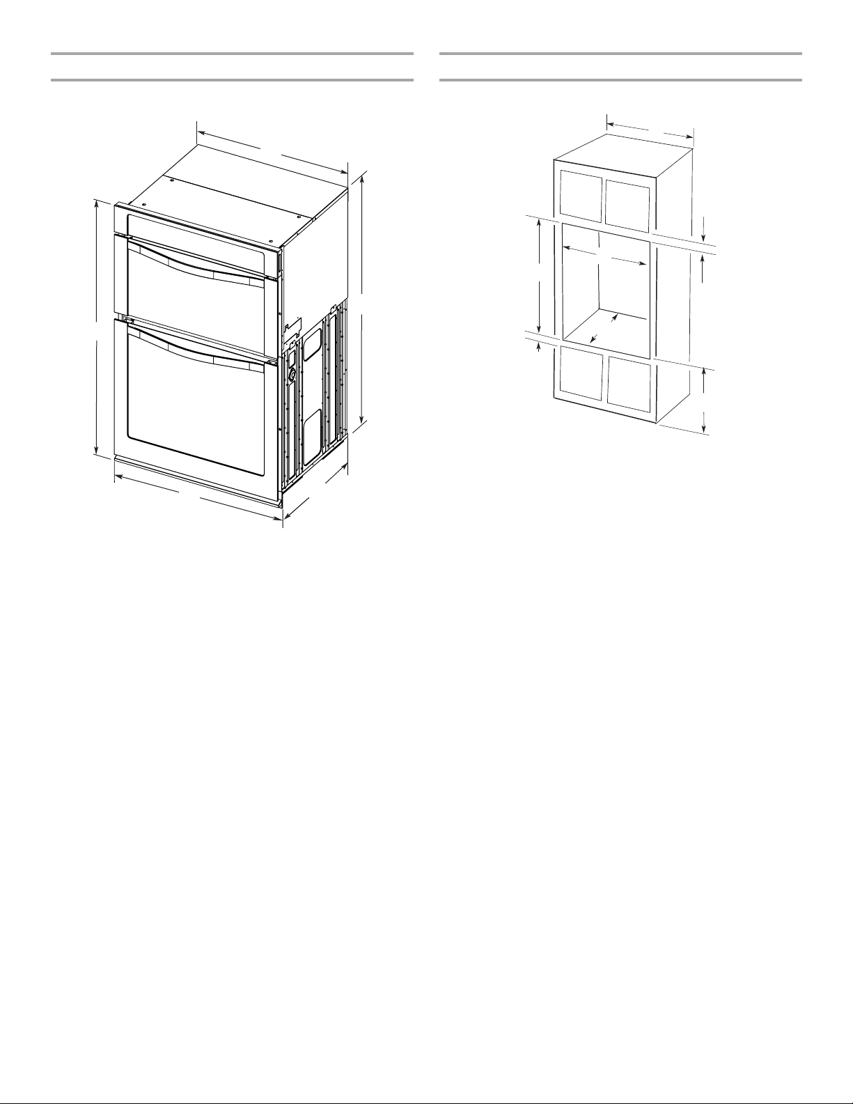
Product Dimensions
Cabinet Dimensions
27" (68.6 cm) and 30" (76.2 cm) Ovens
A
E
27" (68.6 cm) models
A.
42⁹⁄₁₆
" (108.0 cm) overall height
B. 25
⁷⁄₁₆
" (64.6 cm) recessed
width
C. 41" (104.1 cm) recessed height
D. 23
¹⁄₄
" (59.1 cm) max. recessed
depth
E. 27" (68.6 cm) overall width
30" (76.2 cm) models
A.
42⁹⁄₁₆
B. 28
C. 41" (104.1 cm) recessed height
D. 23
depth
E. 30" (76.2 cm) overall width
B
C
D
" (108.0 cm) overall height
¹⁄₂
" (72.3 cm) recessed width
¹⁄₄
" (59.1 cm) max. recessed
27" (68.6 cm) and 30" (76.2 cm) Ovens
A
D
F
G
E
27" (68.6 cm) models
A. 27" (68.6 cm) min. cabinet
width
B. 1" (2.5 cm) top of cutout to
bottom of upper cabinet door
C. 19
¹⁄₄
" (48.9 cm) bottom of
cutout to floor is
recommended.
4"-19
¹⁄₄
" (10.2-48.9 cm) bottom
of cutout to floor is acceptable.
D. 25
¹⁄₂
" (64.8 cm) cutout width
E. 1
¹⁄₂
" (3.8 cm) min. bottom of
cutout to top of cabinet door
F. 4 1
⁵⁄₁₆
" (105 cm)* recommended
cutout height
G. 24" (60.7 cm) cutout depth
30" (76.2 cm) models
A.
30
width
B. 1" (2.5 cm) top of cutout to
bottom of upper cabinet door
C. 19
cutout to floor is
recommended.
4"-19
of cutout to floor is acceptable.
D. 28
E. 1
¹⁄₂
cutout to top of cabinet door
F. 4 1
cutout height
G. 24" (60.7 cm) cutout depth
B
C
" (76.2 cm) min. cabinet
¹⁄₄
" (48.9 cm) bottom of
¹⁄₄
" (10.2-48.9 cm) bottom
¹⁄₂
" (72.4 cm) cutout width
" (3.8 cm) min. bottom of
⁵⁄₁₆
" (105 cm)* recommended
*NOTE: The cabinet height can be between 41" (104.1 cm) and
41½" (105.6 cm) for microwave/oven combination.
3
Electrical Requirements
A
If codes permit and a separate ground wire is used, it is
recommended that a qualified electrical installer determine that
the ground path and wire gauge are in accordance with local
codes.
Check with a qualified electrical installer if you are not sure the
oven is properly grounded.
This oven must be connected to a grounded metal, permanent
wiring system.
Be sure that the electrical connection and wire size are adequate
and in conformance with the National Electrical Code, ANSI/
NFPA 70-latest edition or CSA Standards C22.1-94, Canadian
Electrical Code, Part 1 and C22.2 No. O-M91-latest edition, and
all local codes and ordinances.
A copy of the above code standards can be obtained from:
National Fire Protection Association
1 Batterymarch Park
Quincy, MA 02169-7471
CSA International
8501 East Pleasant Valley Road
Cleveland, OH 44131-5575
Electrical Connection
To properly install your oven, you must determine the type of
electrical connection you will be using and follow the instructions
provided for it here.
■ Oven must be connected to the proper electrical voltage,
amperage, and frequency as specified on the model/serial
number rating plate. See the following illustration.
■ Do not cut the conduit. The length of conduit provided is for
serviceability of the oven.
■ A UL listed or CSA approved conduit connector must be
provided.
■ If the house has aluminum wiring follow the procedure below:
1. Connect a section of solid copper wire to the ends of the
flexible conduit leads.
2. Connect the aluminum wiring to the added section of
copper wire using special connectors and/or tools
designed and UL listed for joining copper to aluminum.
Follow the electrical connector manufacturer's recommended
procedure. Aluminum/copper connection must conform with
local codes and industry accepted wiring practices.
For power requirements for models WOC54EC7A, WOC54EC0A,
WOC95EC0A and MMW9730A, refer to the following table.
Voltage Microwave Oven
and Microwave
Oven with Single
Thermal Oven
Microwave Oven
and Microwave
Oven with Single
Convection Oven
240 VAC 5490 W 5520 W
208 VAC 4590 W 4620 W
240 VAC 30.4 A 30.5 A
208 VAC 28.4 A 28.6 A
For power requirements for models KEMS379B and KEMS309B,
refer to the following table.
Voltage Microwave Oven
and Microwave
Oven with Single
Thermal Oven
Microwave Oven
and Microwave
Oven with Single
Convection Oven
A. Model/serial number plate
■ Models rated from 7.3 to 9.6 kW at 240 volts (5.4 to 7.4 kW
at 208 volts) require a separate 40-amp circuit. Models rated
at 4.8 kW and below at 240 volts (3.6 kW and below at
208 volts) require a separate 20-amp circuit.
■ Model KEHU309B requires a separate 50-amp circuit.
■ A circuit breaker is recommended.
■ Connect directly to the fused disconnect (or circuit breaker
box) through flexible, armored or nonmetallic sheathed,
copper cable (with grounding wire). See “Make Electrical
Connection” section.
■ Flexible conduit from the oven should be connected directly
to the junction box.
240 VAC 6230 W 6260 W
208 VAC 5239 W 5262 W
240 VAC 36.0 A 35.1 A
208 VAC 32.8 A 32.9 A
For power requirements for model KEHU309B, refer to the
following table.
Voltage Microwave Oven and
Microwave Oven with Single
Convection Oven
240 VAC 7560 W
208 VAC 6246 W
240 VAC 40.5 A
208 VAC 37.7 A
4
INSTALLATION INSTRUCTIONS
A
Prepare Built-In Microwave/Oven
Combination
1. Decide on the final location for the oven. Locate existing
wiring to avoid drilling into or severing wiring during
installation.
WARNING
Excessive Weight Hazard
Use two or more people to move and install oven.
Failure to do so can result in back or other injury.
2. To avoid floor damage, set the oven onto cardboard prior to
installation. Do not use handle or any portion of the front
frame for lifting.
3. Remove the shipping materials and tape from the oven.
4. Remove the hardware package from inside the bag
containing literature.
5. Remove and set aside racks and other parts from inside the
oven.
6. Move oven and cardboard close to the oven’s final location.
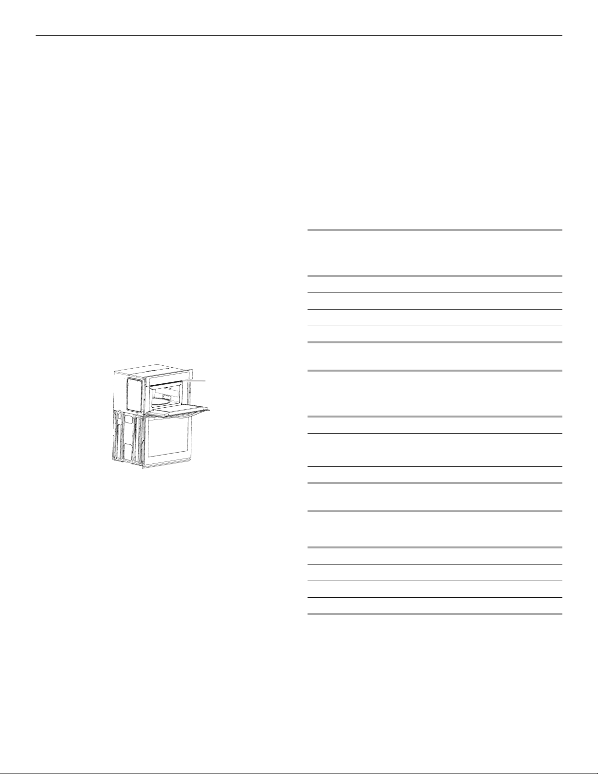
Remove Oven Door
IMPORTANT: Use both hands to remove oven door(s).
1. Open the oven door.
2. Locate the oven door latches in both corners of the oven
door, and rotate the latches forward to the unlocked position.
B
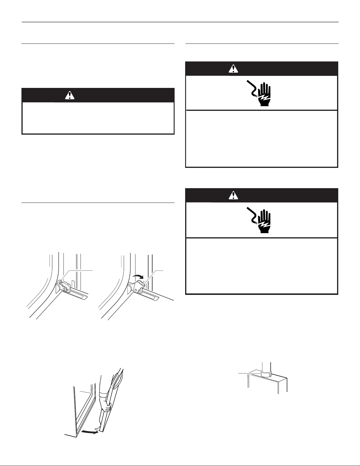
Make Electrical Connection
WARNING
Electrical Shock Hazard
Disconnect power before servicing.
Use 8 gauge solid copper wire.
Electrically ground oven.
Failure to follow these instructions can result in death,
fire, or electrical shock.
IMPORTANT: For model KEHU309B, you must use 6 gauge
copper or 4 gauge aluminum wire.
WARNING
Electrical Shock Hazard
Disconnect power before servicing.
Use 6 gauge copper or 4 gauge aluminum wire.
Electrically ground oven.
Failure to follow these instructions can result in death,
fire, or electrical shock.
A. Oven door latch in locked
position
3. Grasp the edges of the oven door with both hands and close
the oven door until it will no longer close. Lift and pull oven
door toward you and remove. Set the oven door aside on a
covered work surface.
B. Oven door latch in unlocked
position
This oven is manufactured with a neutral (white) power supply
wire and a cabinet-connected green (or bare) ground wire twisted
together.
1. Disconnect power.
2. Feed the flexible conduit from the oven through the opening
in the cabinet.
3. Remove junction box cover, if it is present.
4. Install a UL listed or CSA approved conduit connector to the
junction box.
A
A. UL listed or CSA approved conduit connector
5. Route the flexible conduit from the oven to the junction box
through a UL listed or CSA approved conduit connector.
6. Tighten screws on conduit connector.
7. See “Electrical Connection Options Chart” to complete
installation for your type of electrical connection.
5
 Loading...