

FRONT-LOADING ELECTRIC DRYER
Use &Care Guide
For questions about features, operation/performance, parts accessories or service, call: 1-800-422-1230
In Canada, call for assistance 1-800-461-5681, for installation and service, call: 1-800-807-6777 or visit our website at...
www.kitchenaid.com or www.KitchenAid.ca
SECADORA ELÉCTRICA DE CARGA FRONTAL
Manual de Usoy Cuidado
Si tiene preguntas respecto a las características, funcionamiento/rendimiento, partes, accesorios o servicio técnico, llame al: 1-800-422-1230
Para la instalación y el servicio técnico llame al: 1-800-807-6777 o visite nuestro sitio web en... www.kitchenaid.com
SÉCHEUSE ÉLECTRIQUE À CHARGEMENT
À L’AVANT
Guide d’utilisation etd’entretien
Au Canada, pour assistance composez le 1-800-461-5681, pour installation ou service composez le 1-800-807-6777
ou visitez notre site web à... www.KitchenAid.ca
Table of Contents/Índice/Table des matières...............................................................2-3
Models/Modelos/Modèles KEHS01P, YKEHS01P
8557328A

TABLE OF CONTENTS
ÍNDICE
DRYER SAFETY..............................................................................4
INSTALLATION INSTRUCTIONS..................................................5
Tools and Parts ............................................................................5
Options.........................................................................................5
Location Requirements ...............................................................5
Electrical Requirements - U.S.A. Only......................................... 7
Electrical Requirements - Canada Only.......................................8
Electrical Connection - U.S.A. Only.............................................9
Venting Requirements................................................................13
Plan Vent System.......................................................................14
Install Vent System.....................................................................15
Install Leveling Legs...................................................................15
Level Dryer .................................................................................16
Connect Vent..............................................................................16
Reverse Door Swing ..................................................................16
Complete Installation .................................................................17
DRYER USE ..................................................................................18
Starting Your Dryer.....................................................................18
Stopping Your Dryer ..................................................................19
Pausing or Restarting.................................................................19
Control Locked...........................................................................19
Loading.......................................................................................19
Drying and Cycle Tips................................................................19
Status Lights ..............................................................................20
Cycles.........................................................................................20
Additional Features ....................................................................21
Drying Rack................................................................................22
DRYER CARE ..............................................................................23
Cleaning the Dryer Location ......................................................23
Cleaning the Lint Screen............................................................23
Cleaning the Dryer Interior .........................................................23
Removing Accumulated Lint......................................................23
Vacation and Moving Care.........................................................23
Changing the Drum Light...........................................................24
TROUBLESHOOTING ..................................................................24
ASSISTANCE OR SERVICE.........................................................25
In the U.S.A. ...............................................................................25
In Canada ...................................................................................25
WARRANTY ..................................................................................26
SEGURIDAD DE LA SECADORA................................................27
INSTRUCCIONES DE INSTALACIÓN.........................................28
Herramientas y piezas................................................................28
Opciones ....................................................................................28
Requisitos de ubicación ............................................................28
Requisitos eléctricos - EE. UU...................................................30
Conexión eléctrica - Sólo en EE. UU. ........................................32
Requisitos de ventilación ...........................................................36
Planificación del sistema de ventilación ....................................36
Instalación del sistema de ventilación .......................................38
Instalación de las patas niveladoras..........................................38
Nivelación de la secadora..........................................................39
Conexión del ducto de escape..................................................39
Cómo invertir el cierre de la puerta............................................39
Complete la instalación..............................................................40
USO DE LA SECADORA ..............................................................41
Puesta en marcha de la secadora .............................................41
Detención de la marcha de la secadora ....................................42
Pausa o reanudación de la marcha ...........................................42
Control bloqueado .....................................................................42
Cómo cargar...............................................................................42
Sugerencias de ciclos y secado ................................................42
Luces de estado.........................................................................43
Ciclos..........................................................................................43
Características adicionales ........................................................44
Estante de secado......................................................................45
CUIDADO DE LA SECADORA....................................................46
Limpieza del lugar donde está la secadora...............................46
Limpieza del filtro de pelusa ......................................................46
Limpieza del interior de la secadora ..........................................47
Eliminación de pelusa acumulada .............................................47
Cuidado para las vacaciones y la mudanza..............................47
Cambio de la luz del tambor......................................................47
SOLUCIÓN DE PROBLEMAS......................................................48
AYUDA O SERVICIO TÉCNICO...................................................49
GARANTÍA.....................................................................................50
2

TABLE DES MATIÈRES
SÉCURITÉ DE LA SÉCHEUSE....................................................51
INSTRUCTIONS D'INSTALLATION ............................................52
Outillage et pièces nécessaires .................................................52
Options.......................................................................................52
Emplacement d’installation........................................................52
Spécifications électriques - Canada seulement........................54
Exigences concernant l’évacuation...........................................55
Planification du système d'évacuation......................................56
Installation du conduit d’évacuation..........................................57
Installation des pieds de nivellement.........................................58
Mise à niveau de la sécheuse....................................................58
Conduit d’évacuation.................................................................58
Inversion de l'ouverture de la porte ...........................................58
Achever l’installation ..................................................................60
UTILISATION DE LA SÉCHEUSE................................................61
Mise en marche de la sécheuse ................................................61
Arrêt de la sécheuse ..................................................................62
Arrêt ou remise en marche.........................................................62
Verrouillage des commandes ....................................................62
Chargement................................................................................62
Conseils pour le séchage et les programmes ...........................63
Témoins lumineux ......................................................................63
Programmes...............................................................................64
Caractéristiques supplémentaires .............................................65
Grille de séchage........................................................................66
ENTRETIEN DE LA SÉCHEUSE.................................................67
Nettoyage de l'emplacement de la sécheuse ...........................67
Nettoyage du filtre à charpie......................................................67
Nettoyage de l’intérieur de la sécheuse ....................................68
Retrait de la charpie accumulée ................................................68
Précautions à prendre pour les vacances et avant
un déménagement .....................................................................68
Changement de l’ampoule d’éclairage du tambour..................68
DÉPANNAGE ................................................................................69
ASSISTANCE OU SERVICE.........................................................70
GARANTIE.....................................................................................71
3
DRYER SAFETY
Your safety and the safety of others are very important.
We have provided many important safety messages in this manual and on your appliance. Always read and obey all safety
messages.
This is the safety alert symbol.
This symbol alerts you to potential hazards that can kill or hurt you and others.
All safety messages will follow the safety alert symbol and either the word “DANGER” or “WARNING.”
These words mean:
You can be killed or seriously injured if you don't immediately
DANGER
WARNING
All safety messages will tell you what the potential hazard is, tell you how to reduce the chance of injury, and tell you what can
happen if the instructions are not followed.
IMPORTANT SAFETY INSTRUCTIONS
WARNING:
including the following:
■
Read all instructions before using the dryer.
■
Do not place items exposed to cooking oils in your dryer.
Items contaminated with cooking oils may contribute to
a chemical reaction that could cause a load to catch fire.
■
Do not dry articles that have been previously cleaned in,
washed in, soaked in, or spotted with gasoline, drycleaning solvents, other flammable, or explosive
substances as they give off vapors that could ignite or
explode.
■
Do not allow children to play on or in the dryer. Close
supervision of children is necessary when the dryer is
used near children.
■
Before the dryer is removed from service or discarded,
remove the door to the drying compartment.
■
Do not reach into the dryer if the drum is moving.
■
Do not install or store the dryer where it will be exposed
to the weather.
■
Do not tamper with controls.
To reduce the risk of fire, electric shock, or injury to persons when using the dryer, follow basic precautions,
follow instructions.
can be killed or seriously injured if you don't
You
instructions.
■
Do not repair or replace any part of the dryer or attempt
any servicing unless specifically recommended in this
Use and Care Guide or in published user-repair
instructions that you understand and have the skills to
carry out.
■
Do not use fabric softeners or products to eliminate static
unless recommended by the manufacturer of the fabric
softener or product.
■
Do not use heat to dry articles containing foam rubber or
similarly textured rubber-like materials.
■
Clean lint screen before or after each load.
■
Keep area around the exhaust opening and adjacent
surrounding areas free from the accumulation of lint, dust,
and dirt.
■
The interior of the dryer and exhaust vent should be
cleaned periodically by qualified service personnel.
■
See installation instructions for grounding requirements.
follow
SAVE THESE INSTRUCTIONS
4
INSTALLATION INSTRUCTIONS
Tools and Parts
Gather the required tools and parts before starting installation.
Read and follow the safety instructions provided with any tools
listed here.
■ Flat-blade screwdriver
■ Adjustable wrench that
opens to 1" (2.5 cm) or
hex-head socket wrench
(for adjusting dryer feet)
■ Level
■ Wire stripper (direct wire
installations)
Parts supplied
Remove parts packages from dryer drum. Check that all parts are
included.
4 Leveling legs
NOTE: Do not use leveling legs if installing the dryer on a
pedestal.
Parts needed
Check local codes. Check existing electrical supply and venting.
See “Electrical Requirements” and “Venting Requirements”
before purchasing parts.
■ For close-clearance installations between 31.5" (80.01 cm)
and 37" (93.98 cm), see “Plan Vent System” section for
venting requirements.
■ #2 Phillips screwdriver
■ Vent clamps
■ Caulking gun and
compound (for installing
new exhaust vent)
■ Tin snips (new vent
installations)
■ ¼" nut driver
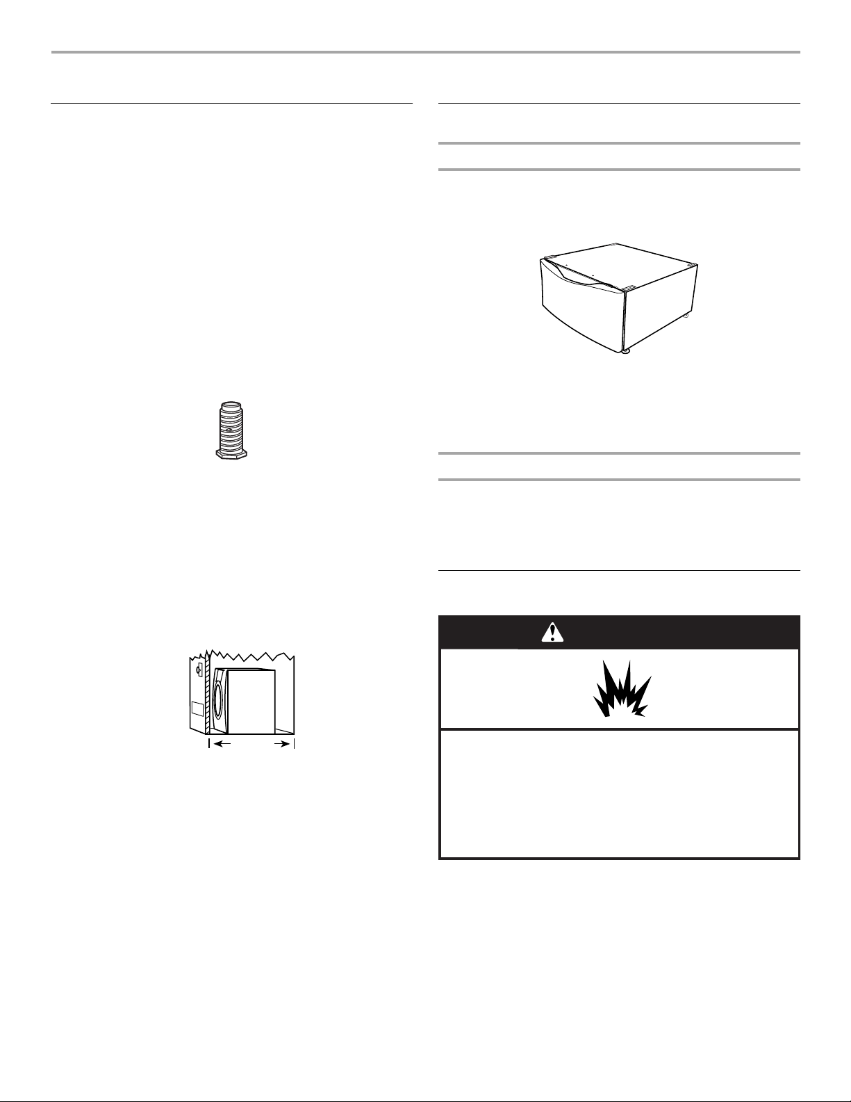
Options
Pedestal
Are you placing the dryer on a pedestal? You may purchase a
pedestal separately for this dryer. This pedestal will add about
13" (33 cm) to the height of your unit for a total height of
approximately 51" (130 cm).
Optional pedestal
To order, call the dealer from whom you purchased your dryer or
refer to the “Assistance or Service” section of this manual. Ask
for Part Number LAB2700PMT (Meteorite) or LAB2700MQ0
(White).
Stack Kit
Are you planning to stack your washer and dryer? To do so, you
will need to purchase a Stack Kit.
To order, call the dealer from whom you purchased your dryer or
refer to the “Assistance or Service” section of this manual. Ask
for Part Number 8541503.
Location Requirements
WARNING
37"
(93.98 cm)
Mobile home installations require metal exhaust system hardware
available for purchase from the dealer from whom you purchased
your dryer. For further information, please refer to the “Assistance
or Service” section of this manual.
Explosion Hazard
Keep flammable materials and vapors, such as
gasoline, away from dryer.
Place dryer at least 18 inches (46 cm) above the floor
for a garage installation.
Failure to do so can result in death, explosion, or fire.
You will need
■ A location that allows for proper exhaust installation. See
“Venting Requirements.”
■ A separate 30 amp circuit.
■ A grounded electrical outlet located within 2 ft (61 cm) of
either side of the dryer. See “Electrical Requirements.”
5
■ A sturdy floor to support the total dryer weight of
200 lbs (90.7 kg). The combined weight of a companion
appliance should also be considered.
■ A level floor with a maximum slope of 1" (2.5 cm) under entire
dryer. If slope is greater than 1" (2.5 cm), install Extended
Dryer Feet Kit, Part Number 279810. Clothes may not tumble
properly and automatic sensor cycles may not operate
correctly if dryer is not level.
■ For a garage installation, you will need to place the dryer at
least 18" (46 cm) above the floor. If using a pedestal, you will
need an additional 6" (15.24 cm).
Do not operate your dryer at temperatures below 45ºF (7ºC). At
lower temperatures, the dryer might not shut off at the end of an
automatic cycle. This can result in longer drying times.
The dryer must not be installed or stored in an area where it will
be exposed to water and/or weather.
Check code requirements. Some codes limit, or do not permit,
installation of the dryer in garages, closets, mobile homes, or
sleeping quarters. Contact your local building inspector.
Installation clearances
■ The location must be large enough to fully open the dryer
door.
■ Additional spacing should be considered for ease of
installation and servicing.
■ Additional clearances might be required for wall, door and
floor moldings.
■ Additional spacing of 1" (2.5 cm) on all sides of the dryer is
recommended to reduce noise transfer.
■ Companion appliance spacing should also be considered.
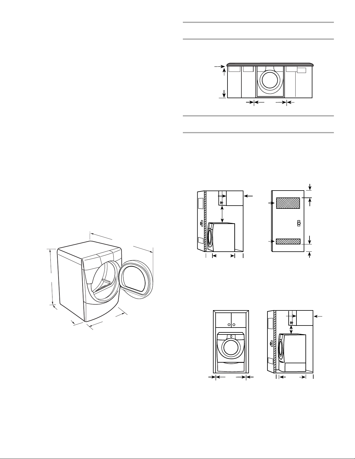
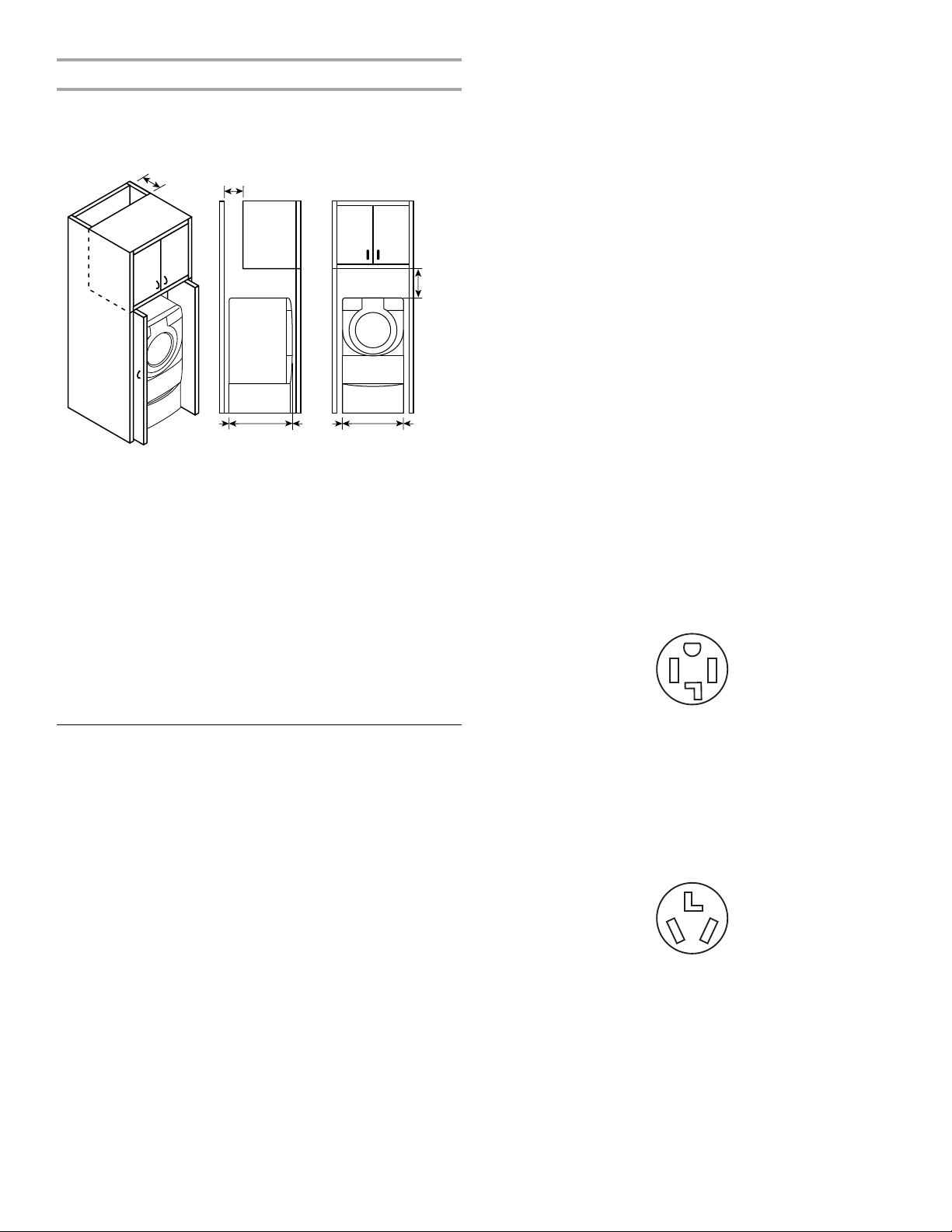
Dryer Dimensions
Minimum installation spacing for custom undercounter
installation
The dimensions shown are for the minimum spacing allowed.
Custom undercounter installation - Dryer only
0"
(0 cm)
38" min.
(96.52 cm)
0"
(0 cm)
27"
(68.6 cm)
0"
(0 cm)
Minimum installation spacing for recessed or closet
installation, with or without a pedestal
■ The dimensions shown are for the minimum spacing allowed.
■ For closet installation, with a door, minimum ventilation
openings in the top and bottom of the door are required.
Louvered doors with equivalent ventilation openings are
acceptable.
Closet installation - Dryer only
3"
14" max.
(35.6 cm)
18" min.
(45.72 cm)
48 in.
(310 cm2)
2
(7.6 cm)
51½"
(130.81 cm)
38"
(96.52 cm)
*31½"
(80 cm)
27"
(68.6 cm)
*Most installations require a minimum 5½" (14 cm) clearance
behind the dryer for the exhaust vent with elbow. See “Venting
Requirements.”
2
24 in.
(155 cm2)
0"
31½"
(80 cm)
0"
(0 cm)
B
(0 cm)
A
A. Side view - closet or confined area
B. Closet door with vents
Recessed or closet installation - Dryer on pedestal
14" max.
(35.6 cm)
18" min.
(45.72 cm)
0"
(0 cm)
27"
(68.6 cm)
0"
(0 cm)
0"
(0 cm)
31½"
(80 cm)
0"
(0 cm)
AB
A. Recessed area
B. Side view - closet or confined area
3"
(7.6 cm)
6
Minimum installation spacing for cabinet installation
)
■ The dimensions shown are for the minimum spacing allowed.
■ For cabinet installation, with a door, minimum ventilation
openings in the top of the cabinet are required.
7" (17.8 cm)
7" (17.8 cm)
9"
(22.9 cm
Electrical Connection
To properly install your dryer, you must determine the type of
electrical connection you will be using and follow the instructions
provided for it here.
■ This dryer is manufactured ready to install with a 3-wire
electrical supply connection. The green cabinet-grounding
conductor is permanently connected to the neutral conductor
(white wire) within the dryer. If the dryer is installed with a
4-wire electrical supply connection, the green cabinetgrounding conductor must be removed from the external
ground connector (green screw), and secured under the
neutral terminal (center or white wire) of the terminal block.
When the green cabinet-grounding conductor is secured
under the neutral terminal (center or white wire) of the
terminal block, the dryer cabinet is isolated from the neutral
conductor.
■ If local codes do not permit the connection of a cabinet
ground connector to the neutral wire, see “Optional 3-wire
connection” section.
■ Use a 4-wire conductor cord when the dryer is installed in a
mobile home or an area where local codes do not permit
grounding through the neutral.
0"
(0 cm)
31¹₂"
(80.0 cm)
0"
(0 cm)
0"
(0 cm)
27"
(68.6 cm)
0"
(0 cm)
Mobile home - Additional installation requirements
This dryer is suitable for mobile home installations. The installation must conform to the Manufactured Home Construction and
Safety Standard, Title 24 CFR, Part 3280 (formerly the Federal
Standard for Mobile Home Construction and Safety, Title 24,
HUD Part 280) or Standard CAN/CSA-Z240 MH.
Mobile home installations require:
■ Metal exhaust system hardware which is available for
purchase from your dealer.
■ Special provisions must be made in mobile homes to
introduce outside air into the dryer. The opening (such as a
nearby window) should be at least twice as large as the dryer
exhaust opening.
Electrical Requirements- U.S.A.Only
It is your responsibility
■ To contact a qualified electrical installer.
■ To be sure that the electrical connection is adequate and in
conformance with the National Electrical Code, ANSI/NFPA
70-latest edition and all local codes and ordinances.
The National Electric Code requires a 4-wire power supply
connection for homes built after 1996, dryer circuits involved
in remodeling after 1996, and all mobile home installations.
A copy of the above code standards can be obtained from:
National Fire Protection Association, One Batterymarch Park,
Quincy, MA 02269.
■ To supply the required 3 or 4 wire, single phase, 120/240-volt,
60-Hz., AC-only electrical supply (or 3 or 4 wire, 120/208-volt
electrical supply, if specified on the serial/rating plate) on a
separate 30-amp circuit, fused on both sides of the line. A
time-delay fuse or circuit breaker is recommended. Connect
to an individual branch circuit. Do not have a fuse in the
neutral or grounding circuit.
■ Do not use an extension cord.
■ If codes permit and a separate ground wire is used, it is
recommended that a qualified electrician determine that the
ground path is adequate.
If using a power supply cord:
Use a UL listed power supply cord kit marked for use with
clothes dryers. The kit should contain:
■ A UL listed 30 amp power supply cord, rated 120/240 volt
minimum. The cord should be type SRD or SRDT and be at
least 4 ft (1.22 m) long. The wires that connect to the dryer
must end in ring terminals or spade terminals with upturned
ends.
■ A UL listed strain relief.
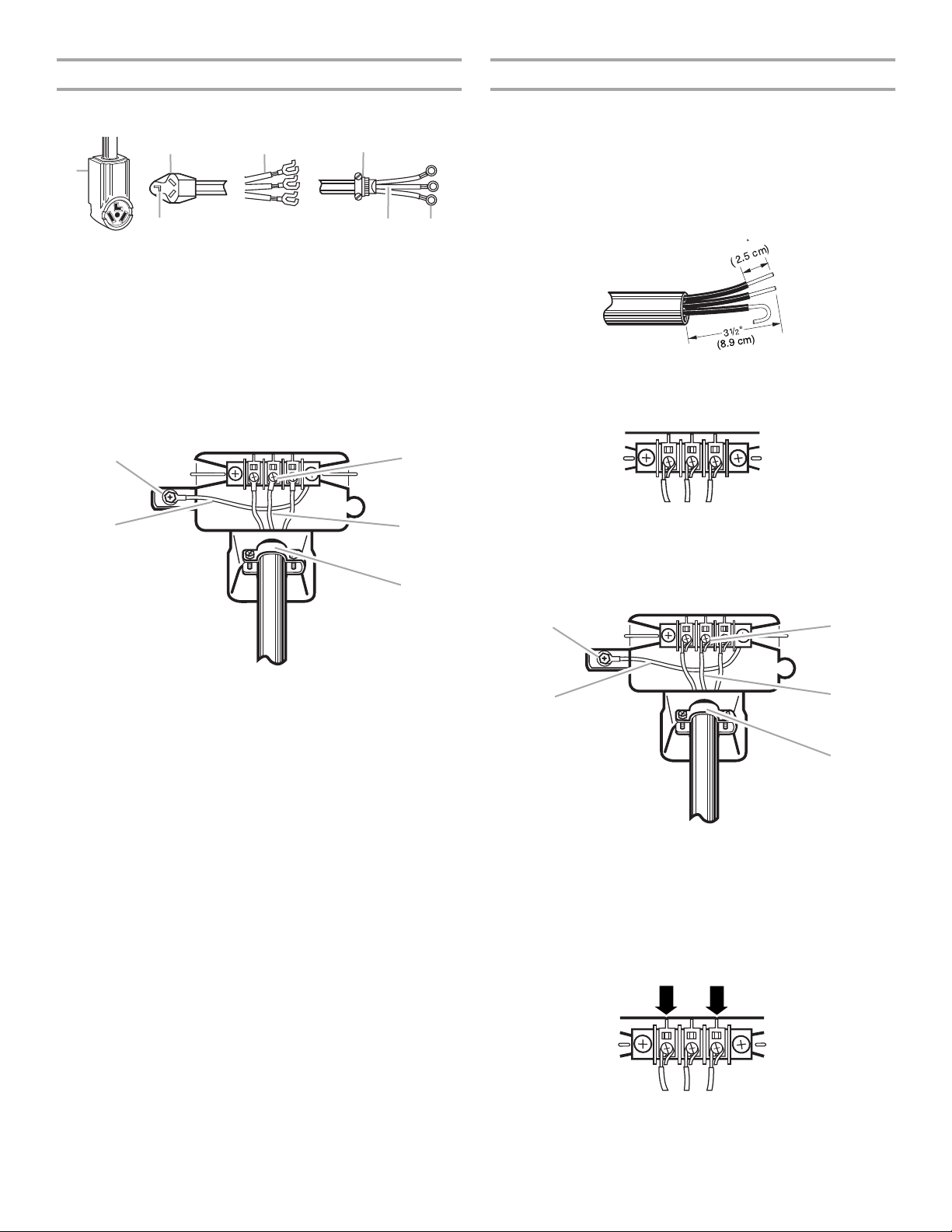
If your outlet looks like this:
4-wire receptacle (14-30R)
Then choose a 4-wire power supply cord with ring or spade
terminals and UL listed strain relief. The 4-wire power supply
cord, at least 4 ft (1.22 m) long, must have 4, 10-gauge copper
wires and match a 4-wire receptacle of NEMA Type 14-30R. The
ground wire (ground conductor) may be either green or bare. The
neutral conductor must be identified by a white cover.
If your outlet looks like this:
3-wire receptacle (10-30R)
Then choose a 3-wire power supply cord with ring or spade
terminals and UL listed strain relief. The 3-wire power supply
cord, at least 4 ft (1.22 m) long, must have 3, 10-gauge copper
wires and match a 3-wire receptacle of NEMA Type 10-30R.
7
If connecting by direct wire:
Power supply cable must match power supply (4-wire or 3-wire)
and be:
■ Flexible armored cable or nonmetallic sheathed copper cable
(with ground wire), protected with flexible metallic conduit. All
current-carrying wires must be insulated.
■ 10-gauge solid copper wire (do not use aluminum).
■ At least 5 ft (1.52 m) long.
GROUNDING INSTRUCTIONS
■
For a grounded, cord-connected dryer:
This dryer must be grounded. In the event of malfunction or
breakdown, grounding will reduce the risk of electric shock
by providing a path of least resistance for electric current.
This dryer uses a cord having an equipment-grounding
conductor and a grounding plug. The plug must be plugged
into an appropriate outlet that is properly installed and
grounded in accordance with all local codes and ordinances.
■
For a permanently connected dryer:
This dryer must be connected to a grounded metal,
permanent wiring system, or an equipment-grounding
conductor must be run with the circuit conductors and
connected to the equipment-grounding terminal or lead on
the dryer.
WARNING:
grounding conductor can result in a risk of electric shock.
Check with a qualified electrician or service representative
or personnel if you are in doubt as to whether the dryer is
properly grounded. Do not modify the plug on the power
supply cord: if it will not fit the outlet, have a proper outlet
installed by a qualified electrician.
Improper connection of the equipment-
SAVE THESE INSTRUCTIONS
Electrical Requirements- CanadaOnly
WARNING
■ To supply the required 4 wire, single phase, 115/230-volt,
60-Hz., AC-only electrical supply on a separate 30-amp
circuit, fused on both sides of the line. A time-delay fuse or
circuit breaker is recommended. Connect to an individual
branch circuit.
■ This dryer is equipped with a CSA International Certified
Power Cord intended to be plugged into a standard 14-30R
wall receptacle. The cord is 5 ft (1.52 m) in length. Be sure
wall receptacle is within reach of dryer’s final location.
4-wire receptacle 14-30R
■ Do not use an extension cord.
If using a replacement power supply cord, it is recommended
that you use Power Supply Cord Replacement Part Number
9831317.
numbers located in the “Assistance or Service” section on this
manual.
For further information, please reference the service
GROUNDING INSTRUCTIONS
■
For a grounded, cord-connected dryer:
This dryer must be grounded. In the event of malfunction or
breakdown, grounding will reduce the risk of electric shock
by providing a path of least resistance for electric current.
This dryer is equipped with a cord having an equipmentgrounding conductor and a grounding plug. The plug must
be plugged into an appropriate outlet that is properly
installed and grounded in accordance with all local codes
and ordinances.
WARNING: Improper connection of the equipment-
grounding conductor can result in a risk of electric shock.
Check with a qualified electrician or service representative
or personnel if you are in doubt as to whether the dryer is
properly grounded. Do not modify the plug provided with the
dryer: if it will not fit the outlet, have a proper outlet installed
by a qualified electrician.
SAVE THESE INSTRUCTIONS
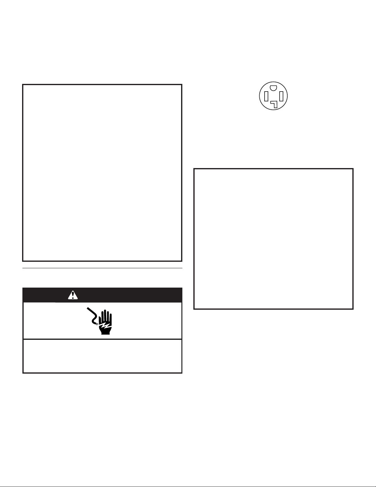
Electrical Shock Hazard
Plug into a grounded 4 prong outlet.
Failure to do so can result in death or electrical shock.
It is your responsibility
■ To contact a qualified electrical installer.
■ To be sure that the electrical connection is adequate and in
conformance with the Canadian Electrical Code, C22.1-latest
edition and all local codes. A copy of the above codes
standard may be obtained from: Canadian Standards
Association, 178 Rexdale Blvd., Toronto, ON M9W 1R3
CANADA.
8
Electrical Connection- U.S.A.Only
Power Supply Cord
WARNING
Fire Hazard
Use a new UL listed 30 amp power supply cord.
Use a UL listed strain relief.
Disconnect power before making electrical connections.
Connect neutral wire (white or center wire) to center
terminal (silver).
Ground wire (green or bare wire) must be connected to
green ground connector.
Connect remaining 2 supply wires to remaining
2 terminals (gold).
Securely tighten all electrical connections.
Failure to do so can result in death, fire, or
electrical shock.
Direct Wire
WARNING
Fire Hazard
Use 10 gauge solid copper wire.
Use a UL listed strain relief.
Disconnect power before making electrical connections.
Connect neutral wire (white or center wire) to center
terminal (silver).
Ground wire (green or bare wire) must be connected to
green ground connector.
Connect remaining 2 supply wires to remaining
2 terminals (gold).
Securely tighten all electrical connections.
Failure to do so can result in death, fire, or
electrical shock.
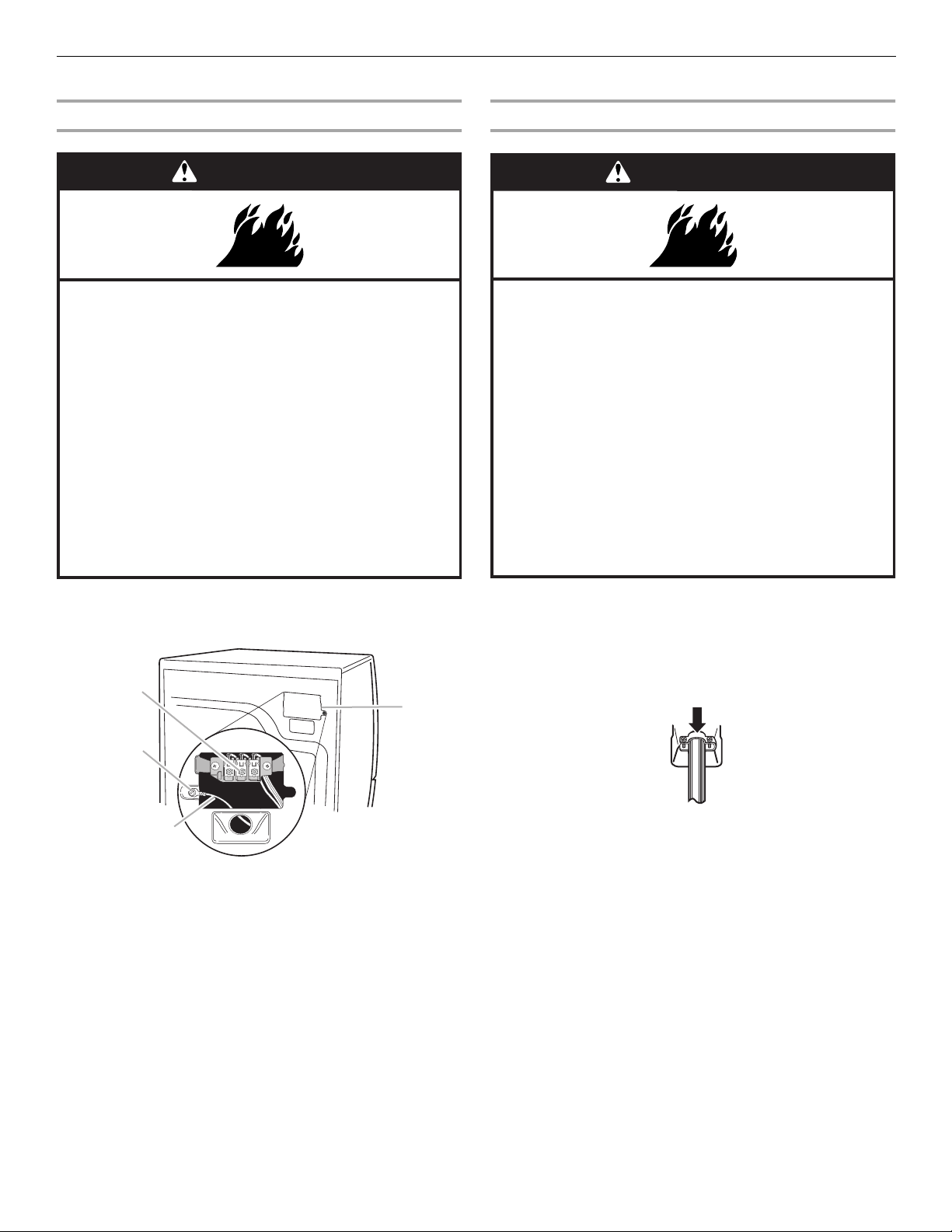
1. Disconnect power.
2. Remove the hold-down screw and terminal block cover.
C
D
B
A
A. Neutral grounding wire (green with yellow stripes)
B. External ground conductor screw
C. Center, silver-colored terminal block screw
D. Terminal block cover and hold-down screw
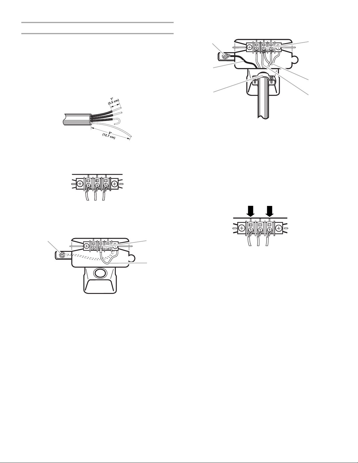
3. Assemble a ³⁄₄" (1.9 cm) UL listed strain relief (UL marking on
strain relief) into the hole below the terminal block opening.
Tighten strain relief screws just enough to hold the two clamp
sections together. Put power supply cord through the strain
relief. The strain relief should have a tight fit with the dryer
cabinet and be in a horizontal position.
4. Now complete installation following instructions for your type
of electrical connection:
4-wire (recommended)
3-wire (if 4-wire is not available)
9
Electrical Connection Options
G
B
If your home has: And you will be
connecting to:
4-wire receptacle
(NEMA Type 14-30R)
A UL listed,
120/240 volt
minimum,
30 amp, dryer
power supply
cord*
Go to Section
4-wire connection:
Power supply cord
1. Remove center terminal block screw.
2. Remove neutral grounding wire (green with yellow stripes)
from external ground conductor screw. Fasten it under center,
silver-colored terminal block screw.
A
C
4-wire direct A fused
disconnect or
4-wire connection:
Direct Wire
circuit breaker
5"
(12.7 cm)
3-wire receptacle
(NEMA type 10-30R)
box*
A UL listed,
120/240 volt
3-wire connection:
Power supply cord
minimum,
30 amp, dryer
power supply
cord*
3-wire direct A fused
disconnect or
3½"
(8.9 cm)
circuit breaker
box*
3-wire connection:
Direct Wire
*If local codes do not permit the connection of a frame-grounding
conductor to the neutral wire, go to “Optional
3-wire Connection” section.
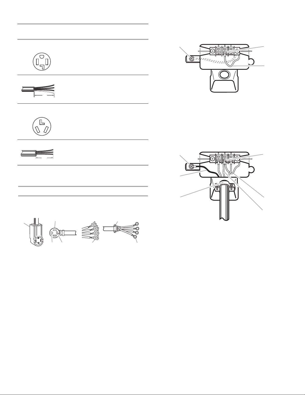
4-wire connection: Power supply cord
IMPORTANT: A 4-wire connection is required for mobile homes
and where local codes do not permit the use of 3-wire
connections.
A
BF
D
C
A. 4-wire receptacle (NEMA type 14-30R)
B. 4-prong plug
C. Ground prong
D. Neutral prong
E. Spade terminals with upturned ends
F. ¾" (1.9 cm) UL listed strain relief
G. Ring terminals
E
A. External ground conductor screw - Dotted line shows
position of NEUTRAL grounding wire before being
moved to center terminal block screw
B. Center silver-colored terminal block screw
C. Green/yellow wire of harness
3. Connect ground wire (green or bare) of power supply cord to
external ground conductor screw. Tighten screw.
4. Connect neutral wire (white or center wire) of power supply
cord under center screw of the terminal block.
A
D
B
C
E
F
A. External ground conductor screw
B. Ground wire (green or bare) wire of power supply cord
³⁄₄
" (1.9 cm) UL listed strain relief
C.
D. Center silver-colored terminal block screw
E. Neutral grounding wire (green with yellow stripes)
F. Neutral wire (white or center wire)
5. Connect the other wires to outer terminal block screws.
Tighten screws.
6. Tighten strain relief screws.
7. Insert tab of terminal block cover into slot of dryer rear panel.
Secure cover with hold-down screw.
10
4-wire connection: Direct wire
B
D
E
3. Connect ground wire (green or bare) of power supply cable to
external ground conductor screw. Tighten screw.
IMPORTANT: A 4-wire connection is required for mobile homes
and where local codes do not permit the use of 3-wire
connections.
Direct wire cable must have 5 ft (1.52 m) of extra length so dryer
can be moved if needed.
Strip 5" (12.7 cm) of outer covering from end of cable, leaving
bare ground wire at 5" (12.7 cm). Cut 1¹⁄₂" (3.8 cm) from 3
remaining wires. Strip insulation back 1" (2.5 cm). Shape ends of
wires into a hook shape.
When connecting to the terminal block, place the hooked end of
the wire under the screw of the terminal block (hook facing right),
squeeze hooked end together and tighten screw. See example
below.
1. Remove center terminal block screw.
2. Remove neutral grounding wire (green with yellow stripes)
from external ground conductor screw. Fasten it under center,
silver-colored terminal block screw.
A
B
C
A. External ground conductor screw
B. Green or bare copper wire of power supply cable
C.
³⁄₄
" (1.9 cm) UL listed strain relief
D. Center silver-colored terminal block screw
E. Neutral grounding wire (green with yellow stripes)
F. Neutral wire (white or center wire)
F
4. Place the hooked end of the neutral wire (white wire) of power
supply cable under the center screw of terminal block (hook
facing right). Squeeze hooked end together. Tighten screw.
5. Place the hooked ends of the other power supply cable wires
under the outer terminal block screws (hooks facing right).
Squeeze hooked ends together. Tighten screws.
A
C
A. External ground conductor screw - Dotted line shows
position of NEUTRAL grounding wire before being
moved to center terminal block screw
B. Center silver-colored terminal block screw
C. Green/yellow wire of harness
6. Tighten strain relief screws.
7. Insert tab of terminal block cover into slot of dryer rear panel.
Secure cover with hold-down screw.
11
3-wire connection: Power supply cord
E
C
3-wire connection: Direct wire
Use where local codes permit connecting cabinet-ground
conductor to neutral wire.
B
D
E
A
C
A. 3-wire receptacle (NEMA type 10-30R)
B. 3-wire plug
C. Neutral prong
D. Spade terminals with up turned ends
³⁄₄
" (1.9 cm) UL listed strain relief
E.
F. R in g t er mi na ls
G. Neutral (white or center wire)
F
G
1. Loosen or remove center terminal block screw.
2. Connect neutral wire (white or center wire) of power supply
cord to the center, silver-colored terminal screw of the
terminal block. Tighten screw.
A
B
C
D
Use where local codes permit connecting cabinet-ground
conductor to neutral wire.
Direct wire cable must have 5 ft (1.52 m) of extra length so dryer
can be moved if needed.
Strip 3¹⁄₂" (8.9 cm) of outer covering from end of cable. Strip
insulation back 1" (2.5 cm). If using 3-wire cable with ground
wire, cut bare wire even with outer covering. Shape ends of wires
into a hook shape.
1
When connecting to the terminal block, place the hooked end of
the wire under the screw of the terminal block (hook facing right),
squeeze hooked end together and tighten screw. See example
below.
1. Loosen or remove center terminal block screw.
2. Place the hooked end of the neutral wire (white or center wire)
of power supply cable under the center screw of terminal
block (hook facing right). Squeeze hooked end together.
Tighten screw.
A. External ground conductor screw
B. Neutral grounding wire (green with yellow stripes)
C. Center silver-colored terminal block screw
D. Neutral wire (white or center wire)
³⁄₄
" (1.9 cm) UL listed strain relief
E.
3. Connect the other wires to outer terminal block screws.
Tighten screws.
4. Tighten strain relief screws.
5. Insert tab of terminal block cover into slot of dryer rear panel.
Secure cover with hold-down screw.
A
B
D
E
A. External ground conductor screw
B. Neutral grounding wire (green with yellow stripes)
C. Center silver-colored terminal block screw
D. Neutral wire (white or center wire)
³⁄₄
" (1.9 cm) UL listed strain relief
E.
3. Place the hooked ends of the other power supply cable wires
under the outer terminal block screws (hooks facing right).
Squeeze hooked ends together. Tighten screws.
12
4. Tighten strain relief screws.
5. Insert tab of terminal block cover into slot of dryer rear panel.
Secure cover with hold-down screw.
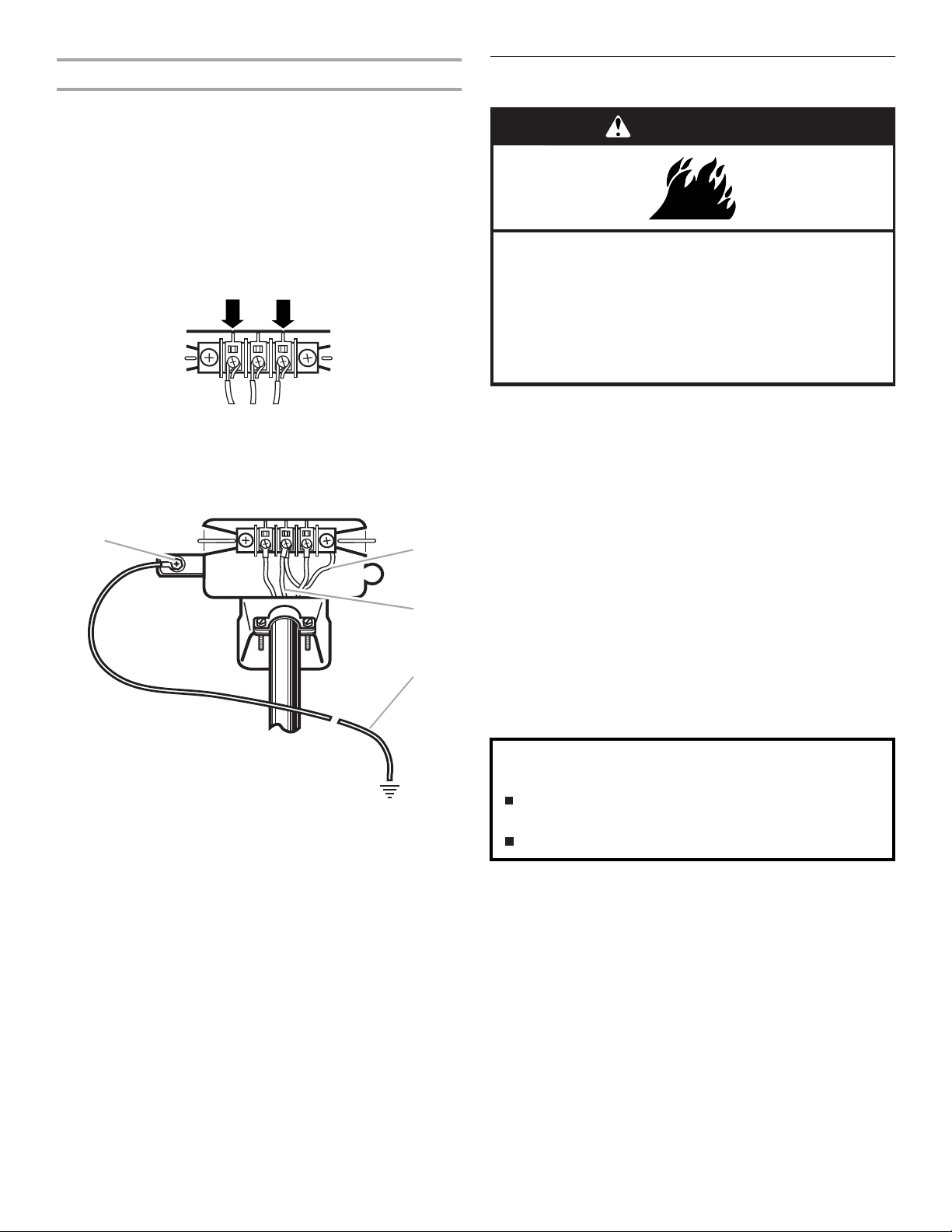
Optional 3-wire connection
D
Use for direct wire or power supply cord where local codes
do not permit connecting cabinet-ground conductor to
neutral wire.
1. Remove center terminal block screw.
2. Remove neutral grounding wire (green with yellow stripes)
from external ground conductor screw. Connect appliance
ground wire and the neutral wire (white or center wire) of
power supply cord/cable under center, silver-colored terminal
block screw. Tighten screw.
3. Connect the other wires to outer terminal block screws.
Tighten screws.
4. Tighten strain relief screws.
5. Insert tab of terminal block cover into slot of dryer rear panel.
Secure cover with hold-down screw.
6. Connect a separate copper ground wire from the external
ground conductor screw to an adequate ground.
A
B
C
Venting Requirements
WARNING
Fire Hazard
Use a heavy metal vent.
Do not use a plastic vent.
Do not use a metal foil vent.
Failure to follow these instructions can result in death
or fire.
WARNING: To reduce the risk of fire, this dryer MUST BE
EXHAUSTED OUTDOORS.
4" (10.2 cm) heavy metal exhaust vent and clamps must be used.
DURASAFE™ vent products are recommended.
DURASAFE™ vent products can be purchased from your dealer
or by calling Whirlpool Parts and Accessories. For more
information, see the “Assistance or Service” section of this
manual.
■ The dryer exhaust must not be connected into any gas vent,
chimney, wall, ceiling, or a concealed space of a building.
■ Do not use an exhaust hood with a magnetic latch.
■ Do not install flexible metal vent in enclosed walls, ceilings or
floors.
■ Use clamps to seal all joints. Exhaust vent must not be
connected or secured with screws or other fastening devices
which extend into the interior of the duct. Do not use duct
tape.
IMPORTANT: Observe all governing codes and ordinances.
A. External ground conductor screw
B. Neutral grounding wire (green with yellow stripes)
C. Neutral wire (white or center wire)
D. Grounding path determined by a qualified electrician
Improper venting can cause moisture and lint to collect
indoors, which may result in:
Moisture damage to woodwork, furniture, paint,
wallpaper, carpets, etc.
Housecleaning problems and health problems.
Use a heavy metal vent. Do not use plastic or metal foil vent.
Rigid metal vent is recommended to prevent crushing and
kinking.
Flexible metal vent must be fully extended and supported when
the dryer is in its final position. Remove excess flexible metal vent
to avoid sagging and kinking that can result in reduced airflow
and poor performance.
An exhaust hood should cap the vent to prevent rodents and
insects from entering the home.
Exhaust hood must be at least 12" (30.5 cm) from the ground or
any object that is in the path of the exhaust (such as flowers,
rocks or bushes, etc.).
If using an existing vent system, clean lint from the entire length
of the system and make sure exhaust hood is not plugged with
lint. Replace any plastic or metal foil vent with rigid metal or
flexible metal vent.
13
Plan Vent System
Typical exhaust installations
Typical installations vent the dryer from the rear of the dryer.
Other installations are possible.
B
C
D
A
E
F
G
H
A. Dryer
B. Elbow
C. Wall
D. Exhaust hood
E. Clamps
F. Rigid metal or flexible metal vent
G. Vent length necessary to connect elbows
H. Exhaust outlet
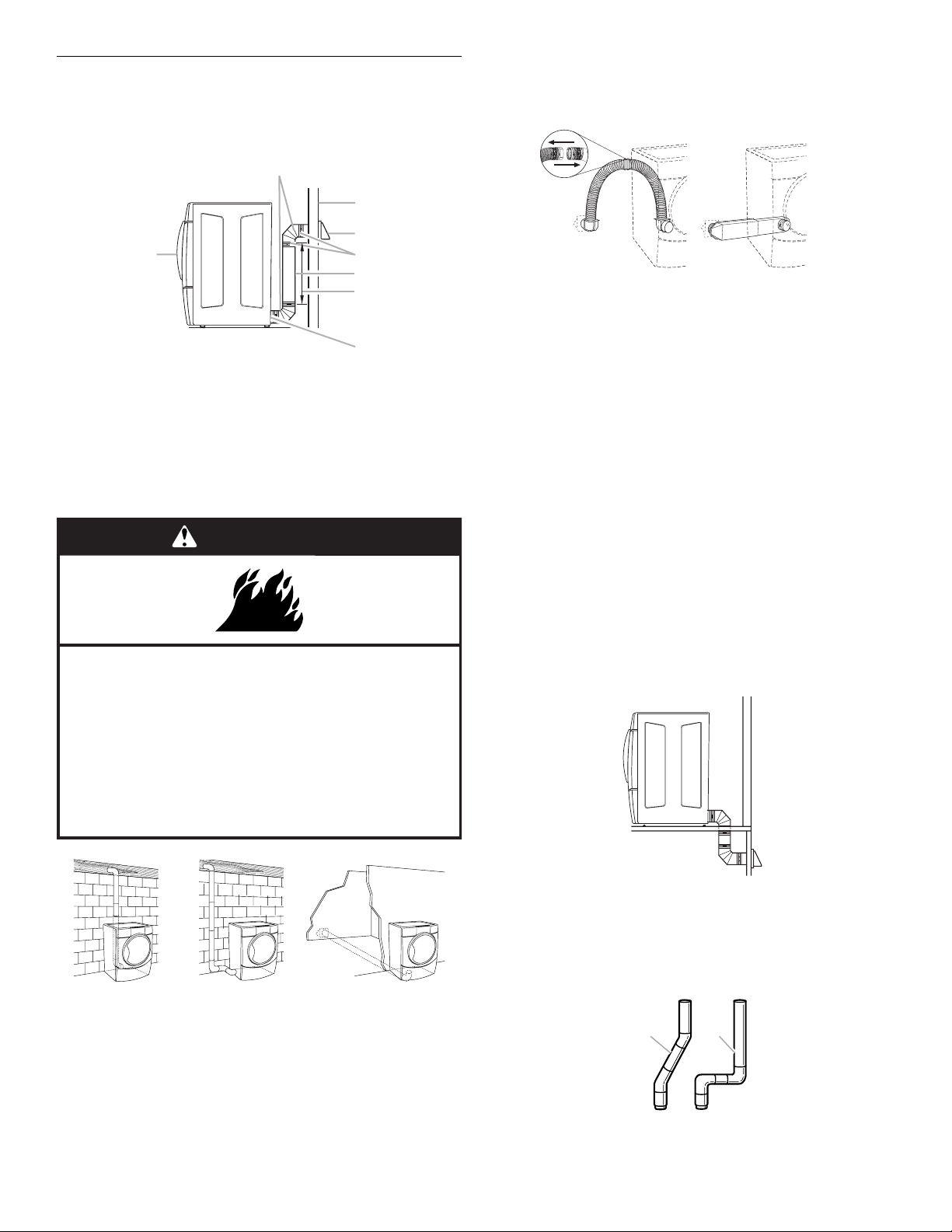
Optional exhaust installations
This dryer can be converted to exhaust out the right side, left
side, or through the bottom. Contact your local dealer to have the
dryer converted.
WARNING
Alternate installations for close clearances
Venting systems come in many varieties. Select the type best for
your installation. Two close-clearance installations are shown.
Refer to the manufacturer’s instructions.
AB
A. Over the top installation (also available with one
offset elbow)
B. Periscope installation
NOTE: The following kits for close clearance alternate
installations are available for purchase. Please see the
“Assistance or Service” section of this manual to order.
■ Over the top Installation:
Part Number 4396028
■ Periscope Installation (For use with dryer vent to wall vent
mismatch):
Part Number 4396037 - 0" (0 cm) to 18" (45.72 cm)
mismatch
Part Number 4396011 - 18" (45.72 cm) to 29" (73.66 cm)
mismatch
Part Number 4396014 - 29" (73.66 cm) to 50" (127 cm)
mismatch
Fire Hazard
Cover unused exhaust holes with one of the
following kits:
279818 (white)
280028 (meteorite)
Contact your local dealer.
Failure to follow these instructions can result in death,
fire, electrical shock, or serious injury.
A
A. Standard rear offset exhaust installation
B. Left or right side exhaust installation
C. Bottom exhaust installation (Not an option with
pedestal installations.)
B
C
Special provisions for mobile home installations
The exhaust vent must be securely fastened to a noncombustible
portion of the mobile home structure and must not terminate
beneath the mobile home. Terminate the exhaust vent outside.
Determine vent length
1. Select the route that will provide the straightest and most
direct path outdoors. Plan the installation to use the fewest
number of elbows and turns. When using elbows or making
turns, allow as much room as possible. Bend vent gradually
to avoid kinking. Avoid 90º turns when possible.
better
good
14
2. Determine vent length.
The maximum length of the exhaust system depends upon:
■ The type of vent (rigid metal or flexible metal).
■ The number of elbows used.
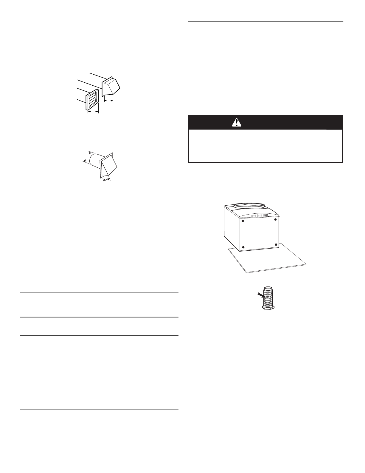
■ Type of hood.
Recommended hood styles are shown here.
B
A
InstallVent System
1. Install exhaust hood. Use caulking compound to seal exterior
wall opening around exhaust hood.
2. Connect vent to exhaust hood. Vent must fit inside exhaust
hood. Secure vent to exhaust hood with 4" (10.2 cm) clamp.
3. Run vent to dryer location. Use the straightest path possible.
See “Determine vent length.” Avoid 90º turns. Use clamps to
seal all joints. Do not use duct tape, screws or other fastening
devices that extend into the interior of the vent to secure
vent.
4"
(10.2 cm)
4"
(10.2 cm)
A. Louvered hood style
B. Box hood style
The angled hood style (shown following) is acceptable.
4"
(10.2 cm)
2½"
(6.4 cm)
See the exhaust vent length chart that matches your hood
type for the maximum vent lengths you can use.
Exhaust systems longer than specified will:
■ Shorten the life of the dryer.
■ Reduce performance, resulting in longer drying times and
increased energy usage.
3. Determine the number of elbows you will need.
IMPORTANT: Do not use vent runs longer than those
specified in the Vent Length Chart.
The following chart helps you determine your maximum vent
length based on the number of 90° turns or elbows you will
need and the type of vent (rigid or flexible metal) and hood
that you will use.
Vent Length Chart
InstallLevelingLegs
WARNING
Excessive Weight Hazard
Use two or more people to move and install dryer.
Failure to do so can result in back or other injury.
1. To protect the floor, use a large flat piece of cardboard from
the dryer carton. Place cardboard under the entire back edge
of the dryer. See illustration.
2. Firmly grasp the body of the dryer (not the console panel).
Gently lay the dryer on the cardboard.
3. Examine the leveling legs. Find the diamond marking.
Number of
90º turns
or elbows
0 Rigid metal
1 Rigid metal
2 Rigid metal
3 Rigid metal
4 Rigid metal
Type of
vent
Flexible metal
Flexible metal
Flexible metal
Flexible metal
Flexible metal
Box or
Louvered
hoods
64 ft (20 m)
36 ft (11 m)
54 ft (16.5 m)
31 ft (9.4 m)
44 ft (13.4 m)
27 ft (8.2 m)
35 ft (10.7 m)
25 ft (7.6 m)
27 ft (8.2 m)
23 ft (7 m)
Angled
hoods
58 ft (17.7 m)
28 ft (8.5 m)
48 ft (14.6 m)
23 ft (7 m)
38 ft (11.6 m)
19 ft (5.8 m)
29 ft (8.8 m)
17 ft (5.2 m)
21 ft (6.4 m)
15 ft (4.6 m)
NOTE: Side and bottom exhaust installations have a 90º turn
inside the dryer. To determine maximum exhaust length, add one
90º turn to the chart.
4. Screw the legs into the leg holes by hand. Use a wrench to
finish turning the legs until the diamond marking is no longer
visible.
5. Place a carton corner post under each of the 2 dryer back
corners. Stand the dryer up. Slide the dryer on the corner
posts until it is close to its final location. Leave enough room
to connect the exhaust vent.
6. Once connection is made and dryer is in final location,
remove corner posts and cardboard.
15
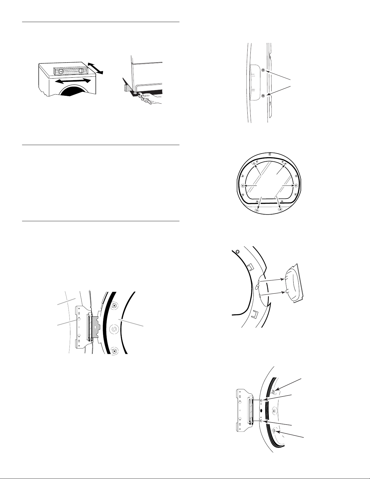
Level Dryer
C
Check the levelness of the dryer. Check levelness first
side to side, then front to back.
If the dryer is not level, prop up the dryer using a wood block.
Use a wrench to adjust the legs up or down and check again for
levelness.
NOTE: It might be necessary to level the dryer again after it has
been moved into its final position.
Connect Vent
1. Using a 4" (10.2 cm) clamp, connect vent to exhaust outlet in
dryer. If connecting to existing vent, make sure the vent is
clean. The dryer vent must fit over the dryer exhaust outlet
and inside the exhaust hood. Make sure the vent is secured
to exhaust hood with a 4" (10.2 cm) clamp.
2. Move dryer into final position. Do not crush or kink vent.
Make sure dryer is level.
3. (On gas models) Check to be sure there are no kinks in the
flexible gas line.
Reverse DoorSwing
You can change your door swing from a right-side opening to a
left-side opening, if desired.
3. Lay the dryer door on a flat, protected surface with the inside
door assembly facing up. Remove the last screw from Step 1.
Remove the 2 screws holding the handle to the door.
4. Remove the 6 screws to release the outer door assembly
from the inner door assembly (see illustration). It is important
that you remove only the 6 indicated screws.
5. Lift the inner door assembly off of the outer door assembly.
Unsnap the handle from the outer door assembly, move it to
the other side, and snap in. Set the outer door assembly
aside.
Remove the door
1. Open the dryer door. Remove the 4 screws that hold the door
hinge on the front panel of the dryer. Loosen, but do not
remove, the screw with the top keyhole opening last (second
from the top).
A
B
A. Dryer
B. Do not remove
C. Dryer door
2. Lift and pull forward on the door so that the keyhole clears
the screw head. Remove the door.
Reverse the hinge and hinge bracket
1. Place the inner door, screw head side up, on the work
surface.
2. Remove the 4 screws that hold the hinge to the door.
16
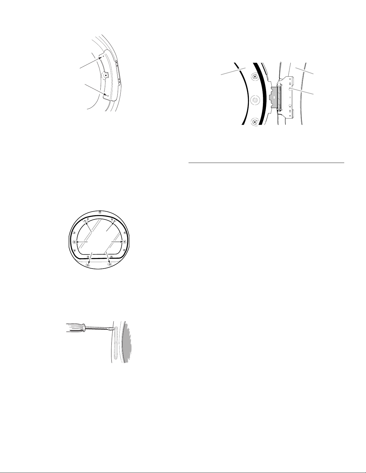
3. Remove the 2 screws that hold the handle bracket to the
B
C
door.
4. Move hinge to the other side and reattach with the 4 screws
removed in Step 2.
5. Move handle bracket to the other side and reattach with the 2
screws removed in Step 3.
6. Set the inner door assembly aside.
6. Insert a screw in the second opening from the top of the
hinge opening and partially tighten. Hang the door by placing
the top hinge keyhole over the second screw head and
tighten the screw. By putting this screw in first, the door will
hang in place while you insert and tighten the remaining 4
screws.
A
A. Dryer door
B. Dryer
C. Insert this screw first
Reinstalling the door
1. Check for fingerprints on the glass. Clean if necessary.
2. Place the inner door assembly into the outer door assembly.
Align the hinge in the opening on the side. To fit correctly, the
inside door assembly edge is completely inside the outside
door assembly edge.
3. Reassemble the inner and outer door assemblies with the
6 screws.
4. Replace the 2 handle screws for the door handle of the door
assembly.
5. Use a small flat-blade screwdriver to remove hole plugs in the
door opening. Slide the head of the screwdriver under the
cap of each hole plug, being careful not to scratch the dryer
surface. Lift up. Remove the hole plugs in the door opening
and insert in the opposite side.
7. Close the door and check that it latches securely.
Complete Installation
1. Check to be sure all parts are now installed. If there is an
extra part, go back through the steps to see which step was
skipped.
2. Check to be sure you have all of your tools.
3. Dispose of/recycle all packaging materials.
4. Check the dryer’s final location. Be sure the vent is not
crushed or kinked.
5. Check to be sure the dryer is level. See “Level Dryer.”
6. Plug into a grounded outlet. Turn power on.
7. Remove the blue protective film on the console and any tape
remaining on the dryer.
8. Read “Dryer Use.”
9. Wipe the dryer drum interior thoroughly with a damp cloth to
remove any dust.
10. Set the dryer on a full heat cycle (not an air cycle) for
20 minutes and start the dryer.
If the dryer will not start, check the following:
■ Controls are set in a running or “On” position.
■ Start button has been pushed firmly.
■ Dryer is plugged into a grounded outlet.
■ Electrical supply is connected.
■ House fuse is intact and tight, or circuit breaker has not
tripped.
■ Dryer door is closed.
11. When the dryer has been running for 5 minutes, open the
dryer door and feel for heat.
If you do not feel heat, turn the dryer off and check the
following:
■ There may be 2 fuses or circuit breakers for the dryer. Check
to make sure both fuses are intact and tight, or that both
circuit breakers have not tripped. If there is still no heat,
contact a qualified technician.
NOTE: You may notice a burning odor when the dryer is first
heated. This odor is common when the heating element is first
used. The odor will go away.
17
DRYER USE
Starting Your Dryer
WARNING
Explosion Hazard
Keep flammable materials and vapors, such as
gasoline, away from dryer.
Do not dry anything that has ever had anything
flammable on it (even after washing).
Failure to follow these instructions can result in death,
explosion, or fire.
WARNING: To reduce the risk of fire, electric shock, or injury to
persons, read the IMPORTANT SAFETY INSTRUCTIONS before
operating this appliance.
The following is a guide to starting your dryer. Please refer to
specific sections of this manual for more detailed information.
1. Clean lint screen before or after each cycle. See “Cleaning
the Lint Screen.”
2. Place laundry into dryer and shut door. See “Loading.”
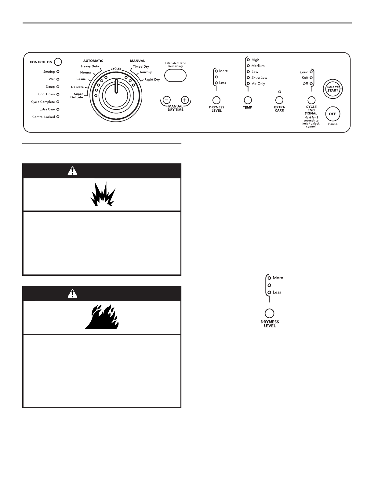
3. Rotate the dial to select either an Automatic or Manual Cycle
then press the CONTROL ON button. The preset settings and
drying time for the cycle chosen will be displayed.
To use an Automatic Cycle
■ Point the dial to an Automatic Cycle.
■ Select DRYNESS LEVEL to adjust how dry you want the
load to be. The time displayed is an estimated length of
the cycle based on the Dryness Level selected. As the
cycle runs, the control senses the dryness of the load and
adjusts the time automatically for the selected Dryness
Level.
WARNING
Fire Hazard
No washer can completely remove oil.
Do not dry anything that has ever had any type of oil on
it (including cooking oils).
Items containing foam, rubber, or plastic must be dried
on a clothesline or by using an Air Cycle.
Failure to follow these instructions can result in death
or fire.
18
NOTE: Time is not adjustable for Automatic Cycles. Pressing
the Manual Dry Time (- or +) buttons will cause a triple beep,
indicating that the time cannot be changed.
■ Press the EXTRA CARE feature button if this option is
desired.
■ Press the CYCLE END SIGNAL button to set signal
volume to desired level.
■ Press (and hold) HOLD TO START button until dryer starts
(about 1 second).
Once an Automatic cycle has started, the Extra Care feature
and the Cycle End Signal level can be adjusted. Press the
OFF button twice to stop the dryer and clear the settings,
allowing you to select another cycle and Dryness Level.
To use a Manual Cycle
■ Rotate the dial to select a Manual Cycle.
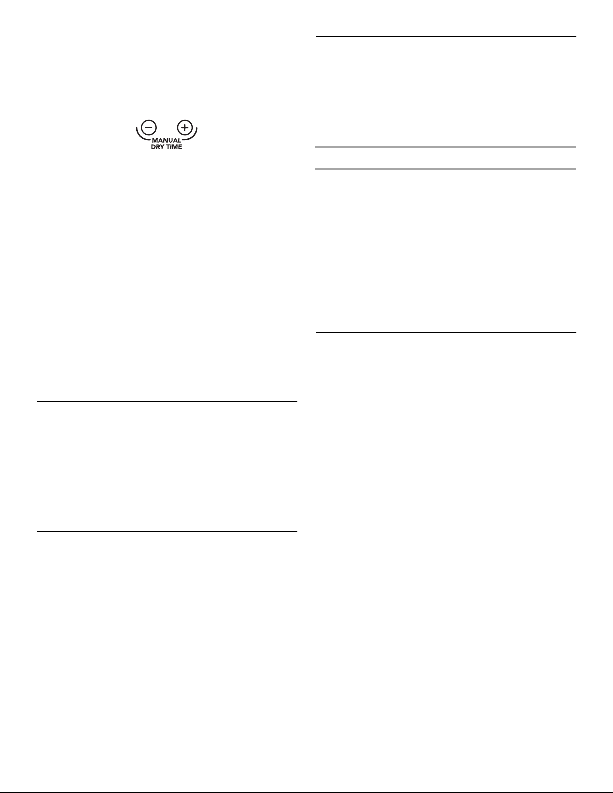
Press MANUAL DRY TIME (- or +) buttons until the desired
drying time is displayed. Tap - or + and the time will change
by 1-minute intervals. Press and hold - or + and the time will
change by 5-minute intervals. The initial time displayed is the
actual drying time.
Loading
Properly loading your dryer can lower your utility bill and prolong
the life of your garments.
Loading suggestions
■ Load the dryer by the amount of space items take up, not by
their weight.
■ Do not overload the dryer. This causes wrinkling and uneven
drying.
NOTE: The Manual Dry Time feature can be used only with
Manual Cycles.
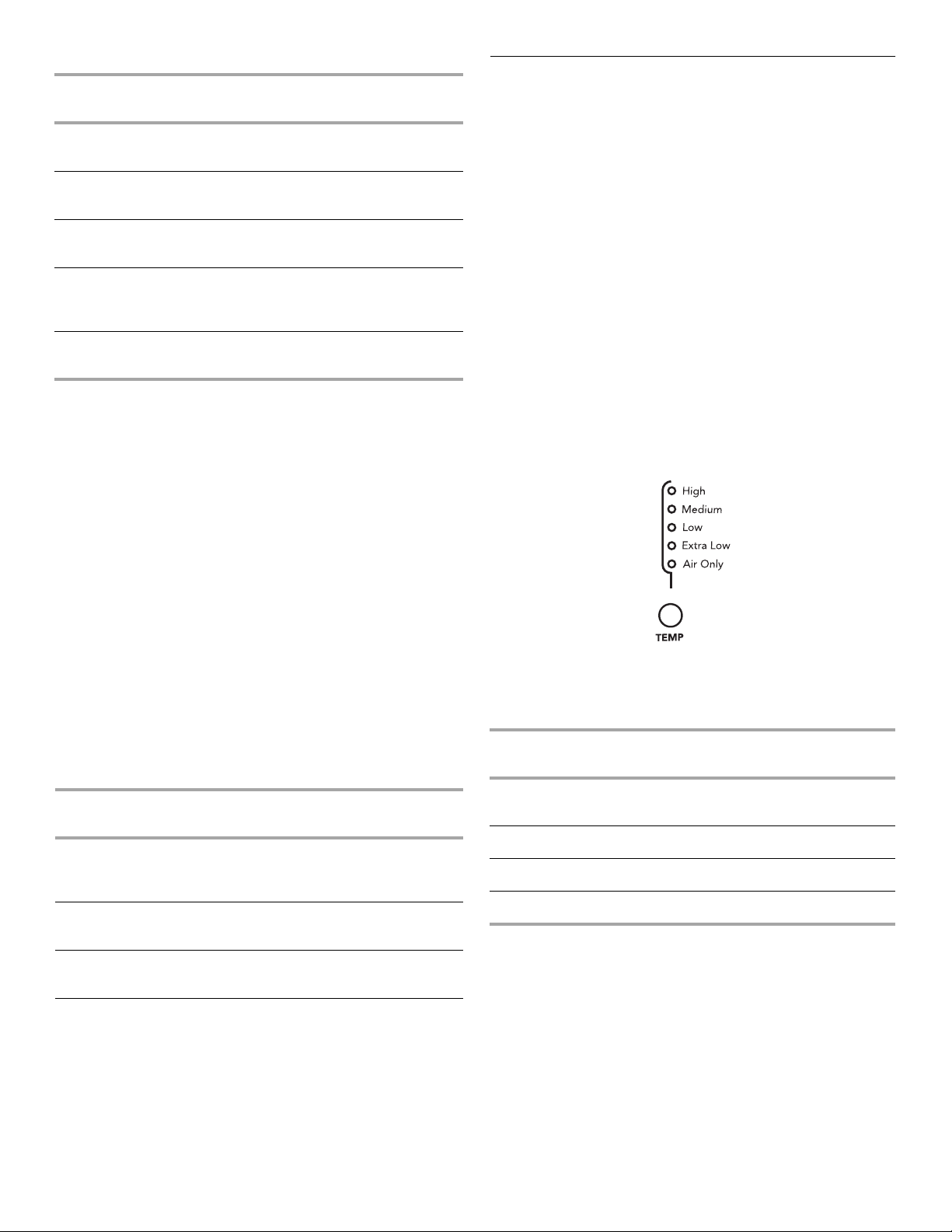
■ Press TEMP until the desired temperature glows.
NOTE: Pressing the Dryness Level button will cause the triple
beep indicating that this option is not selectable. Also, a
Dryness Level is not indicated.
■ Press the EXTRA CARE feature button if this option is
desired.
■ Press the CYCLE END SIGNAL button to set volume to
desired level.
■ Press (and hold) HOLD TO START button until dryer starts
(about 1 second).
While a Manual Cycle is running, you can change the settings
for Time, Temperature, the Extra Care feature, and the Cycle
End Signal. Press the OFF button twice to stop the dryer and
clear the settings, allowing you to select another cycle.
StoppingYour Dryer
To stop your dryer at any time
Press OFF twice or open the door.
Pausing orRestarting
To pause the dryer at any time
Open the door or press OFF once.
To restart the dryer
Close the door and press (and hold) HOLD TO START button until
dryer starts.
NOTE: Drying will continue from where the cycle was interrupted
if you close the door and press Start within 5 minutes. If the cycle
is interrupted for more than 5 minutes, the dryer will shut off.
Select new cycle settings before restarting the dryer.
Control Locked
This feature allows you to lock your settings to prevent
unintended use of the dryer. You can also use the Control Locked
feature to prevent unintended cycle or option changes during
dryer operation.
To enable the Control Locked feature when dryer is
running:
Press and hold the CYCLE END SIGNAL button for 3 seconds.
The control is locked when a single beep is heard and the Control
Locked status light is on.
■ When the dryer is off, it is not necessary to press the Control
On button before activating the Control Locked feature.
To unlock:
Press and hold the CYCLE END SIGNAL button for 3 seconds to
turn this feature off.
NOTE: When the dryer is running and Control Locked is on, the
dryer can be stopped by pressing the Off button, but can’t be
restarted until the control is unlocked.
Super Capacity Plus Dryers
Heavy Work Clothes
4 jeans
4 workpants
4 workshirts
Towels
10 bath towels
10 hand towels
Mixed Load
3 sheets (1 king, 2 twin)
4 pillowcases
3 shirts
3 blouses
2 sweatpants
2 sweatshirts
14 washcloths
9 T-shirts
9 shorts
10 handkerchiefs
Drying andCycle Tips
Select the correct cycle and dryness level or temperature for your
load. If an Automatic Cycle is running, the display shows the
estimated cycle time when your dryer is automatically sensing
the dryness level of your load. If a Manual Cycle is running, the
display shows the exact number of minutes remaining in the
cycle.
Cool Down tumbles the load without heat during the last few
minutes of all cycles. Cool Down makes the loads easier to
handle and reduces wrinkling. The length of the Cool Down
depends on the load size and dryness level.
Drying tips
■ Follow care label directions when they are available.
■ If desired, add a fabric softener sheet. Follow package
instructions.
■ Remove the load from the dryer as soon as tumbling stops to
reduce wrinkling. This is especially important for permanent
press, knits, and synthetic fabrics.
■ Avoid drying heavy work clothes with lighter fabrics. This
could cause overdrying of lighter fabrics, leading to increased
shrinkage or wrinkling.
Cycle tips
■ Dry most loads using the preset cycle settings.
■ Refer to the Automatic or Manual Preset Cycle Settings chart
(in the “Cycles” section) for a guide to drying various loads.
■ Drying temperature and Dryness Level are preset when
you choose an Automatic Cycle. You can choose a
different dryness level, depending on your load by
pressing the DRYNESS LEVEL button to select MORE or
LESS.
■ If you wish to adjust the cycle length of a Manual Cycle,
you must press the MANUAL DRY TIME (- or +) buttons.
Adjust the temperature of a Manual Cycle by pressing
TEMP until the desired temperature is selected.
NOTE: You cannot choose a Dryness Level with Manual
Cycles.
19

StatusLights
You may follow the progress of your dryer with the drying status
indicator lights.
Sensing
When a cycle is first turned on, the SENSING light glows until a
wet item is detected.
■ In an Automatic cycle, if a wet item has not been detected
within 10 minutes, the Sensing light will turn off and the dryer
will shut down.
■ In a Manual cycle, if a wet item is not detected after
10 minutes the Wet light turns on and the selected cycle
continues.
Cycles
Select the drying cycle that matches the type of load you are
drying (see Automatic Preset or Manual Preset Cycle Settings
charts).
Cycle control knob
Automatic Cycles
Automatic Cycles allow you to match the cycle to the load you
are drying. See the following Automatic Preset Cycle Settings
chart. Each cycle dries certain fabrics at the recommended
temperature. A sensor detects the moisture in the load and
automatically adjusts the drying time for optimal drying.
Wet
The WET light will turn on when a wet item has been detected in
the dryer. The Wet light will remain on until:
■ The damp dry point is reached in an Automatic cycle.
■ The dryer enters the cool down period in a Manual cycle.
Damp
The DAMP light indicates that the load has reached the damp dry
level.
NOTE: The Damp light is not used with manual cycles.
Cool Down
The COOL DOWN light glows during the cool down part of the
cycle. Laundry is cooling down for ease in handling.
Cycle Complete
The CYCLE COMPLETE light glows when a drying cycle is
finished. If the Extra Care feature has been selected, the Extra
Care feature indicator light will also be on.
The Cycle Complete light turns off one hour after the end of a
drying cycle (including the Extra Care cycle of 2 hours), when Off
is pressed, or when the door is opened.
Extra Care Feature
The EXTRA CARE feature light glows when this option is
selected. This indicator stays on with the Cycle Complete light.
Heavy Duty
Use this cycle to get High heat for heavy fabrics such as cotton
towels or bedspreads.
Normal
Use this cycle to get Medium heat for drying sturdy fabrics such
as work clothes.
Casual
Use this cycle to get Medium heat for drying no-iron fabrics, such
as sport shirts, casual business clothes and permanent press
blends.
Delicate
Use this cycle to get Low heat for drying synthetic fabrics,
washable knit fabrics and no-iron finishes.
Super Delicate
Use this cycle to get Extra Low heat to gently dry items such as
lingerie, exercise wear, or sheer curtains.
Control Locked
The CONTROL LOCKED light glows when this option is enabled.
Indicator lights
Other indicator lights on the control panel show Cycle,
Temper-ature, and Cycle End Signal settings selected.
The time display will indicate the estimated or actual time
remaining in a cycle.
20
Automatic Preset Cycle Settings
Automatic Cycles
Load Type
HEAVY DUTY
Heavyweight, towels
NORMAL
Corduroys, work clothes
CASUAL
Permanent press, synthetics
DELICATE
Lingerie, blouses, washable
woolens
SUPER DELICATE
Exercise wear, sheer curtains, lace
*Estimated Time with Dryness Level (medium) setting.
Te mp . T im e *
(Minutes)
High 40
Medium 34
Medium 36
Low 28
Extra Low 22
Manual Cycles
Use Manual Cycles to select a specific amount of drying time and
a drying temperature. When a Manual Cycle is selected, the
ESTIMATED TIME REMAINING display shows the actual time
remaining in your cycle. You can change the actual time in the
cycle by pressing the Manual Dry Time (- or +) buttons.
Additional Features
Extra Care Feature
When you are unable to remove a load of clothes from the dryer
as soon as it stops, wrinkles can form. The Extra Care feature
periodically tumbles, rearranges and fluffs the load to help reduce
wrinkles.
■ Press the Extra Care feature to get up to 120 minutes of heat-
free, periodic tumbling at the end of a cycle.
■ Stop at any time by pressing the Extra Care feature or
opening the dryer door.
■ For the Casual Cycle, the Extra Care feature is preset to “On.”
The other Automatic Cycles will retain the Extra Care feature
setting. (For example, if you select the Extra Care feature in
the Normal cycle, the Extra Care feature will be on the next
time you select the Normal cycle.)
NOTE: If you do not select the Extra Care feature, the dryer stops
after the cool down period.
Temperature
Temperature settings are used with the Manual Cycles. Press
TEMP until the desired temperature setting glows. Temperature
settings cannot be used with the Automatic Cycles.
Timed Dry
Use this cycle to complete drying if items are still damp after an
Automatic Cycle. Timed Dry is also useful for drying heavyweight
and bulky items, such as bedspreads and work clothes.
Touchup
Use this setting to remove wrinkles from items, such as clothes
packed in a suitcase or items wrinkled from being left in the dryer
too long.
Rapid Dry
Use this cycle for drying small loads or loads that need a short
drying time.
Manual Preset Cycle Settings
Manual Cycles
Load Type
TIMED DRY
Heavyweight, bulk,
bedspreads, work clothes
TOUCHUP
Remove wrinkles
RAPID DRY
Small loads
Temp. Default Time
(Minutes)
High 40
Medium 20
High 27
Air Only
Use the Air Only setting for items that require drying without heat
such as rubber, plastic and heat-sensitive fabrics. This chart
shows examples of items that can be dried using Air Only.
Type of Load Time*
Foam rubber - pillows, padded bras,
stuffed toys
Plastic - Shower curtains, tablecloths 20 - 30
Rubber-backed rugs 40 - 50
Olefin, polypropylene, sheer nylon 10 - 20
*Reset time to complete drying, if needed.
(Minutes)
20 - 30
When using Air Only
■ Check to see that coverings are securely stitched.
■ Shake and fluff pillows by hand periodically during the cycle.
■ Dry item completely. Foam rubber pillows are slow to dry.
NOTE: Automatic Cycles are not available when using the Air
Only setting.
21
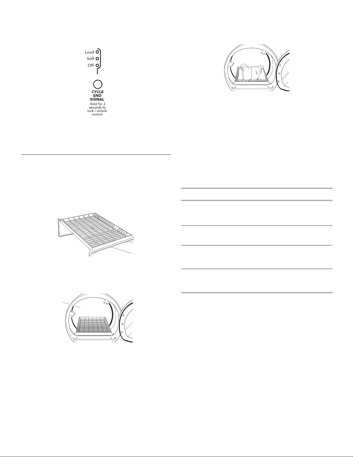
Cycle End Signal
The Cycle End Signal produces an audible sound when the
drying cycle is finished. Promptly removing clothes at the end of
the cycle reduces wrinkling.
Press and release the CYCLE END SIGNAL to adjust the sound
level or turn off the signal.
NOTE: When the Extra Care feature is selected and the Cycle
End Signal is on, an audible sound will emit every 5 minutes until
the clothes are removed, or the Extra Care feature is finished.
Drying Rack
The drying rack is useful for drying items you would not
necessarily want to tumble dry or that you would normally line dry
(for example, sweaters).
To use the drying rack
Do not remove the lint screen.
1. Open dryer door.
3. Put the wet items on top of the rack. Leave space between
the items so air can reach all the surfaces.
NOTE: Do not allow items to hang over the edge of the rack.
4. Close the door.
5. Select a timed drying cycle and temperature, or an air cycle
(see following chart). Items containing foam, rubber, or plastic
must be dried on a clothesline or by using the Air Only
temperature setting.
6. You must select a time by pressing the MANUAL DRY TIME
(- or +) buttons. Reset time as needed to complete drying.
Refer to the following table.
7. Press (and hold) HOLD TO START button (about 1 second).
NOTE: You must remove rack for normal tumbling. Do not use
automatic cycles with the drying rack.
This chart shows examples of items that can be rack dried and
the suggested cycle, temperature setting and drying time. Actual
drying time will depend on the amount of moisture items hold.
Rack Dry Setting Temp. Time*
Wool Sweaters
Block to shape and lay flat on
the rack
Timed
Dry
Low 60
A
A. Front edge
2. Place drying rack inside dryer drum, positioning the back wire
on the ledge of the inner dryer back panel. Push down on
front edge of drying rack to secure over the lint screen.
A
A. Dryer back panel
Stuffed toys or pillows
Cotton or polyester fiber filled
Stuffed toys or pillows
Foam rubber filled
Sneakers or canvas shoes Timed
*(Minutes) Reset time to complete drying, if needed.
Timed
Dry
Timed
Dry
Dry
Low 60
Air Only
(no
heat)
Air Only
(no
heat)
90
90
22

DRYER CARE
Cleaning theDryer Location
Keep dryer area clear and free from items that would obstruct the
flow of combustion and ventilation air.
WARNING
Explosion Hazard
Keep flammable materials and vapors, such as
gasoline, away from dryer.
Place dryer at least 18 inches (46 cm) above the floor
for a garage installation.
Failure to do so can result in death, explosion, or fire.
Cleaning the LintScreen
Every load cleaning
The lint screen is located in the door opening of the dryer. Clean it
before or after each load. A screen blocked by lint can increase
drying time.
To clean
1. Pull the lint screen straight up. Roll lint off the screen with
your fingers. Do not rinse or wash screen to remove lint. Wet
lint is hard to remove.
Clean the lint screen with a nylon brush every 6 months, or more
frequently, if it becomes clogged due to a residue buildup.
To wash
1. Roll lint off the screen with your fingers.
2. Wet both sides of lint screen with hot water.
3. Wet a nylon brush with hot water and liquid detergent. Scrub
lint screen with the brush to remove residue buildup.
4. Rinse screen with hot water.
5. Thoroughly dry lint screen with a clean towel. Replace screen
in dryer.
Cleaning theDryer Interior
To clean dryer drum
1. Make a paste with powdered laundry detergent and very
warm water.
2. Apply paste to a soft cloth.
OR
Apply a liquid, nonflammable household cleaner to the
stained area and rub with a soft cloth until all excess dye and
stains are removed.
3. Wipe drum thoroughly with a damp cloth.
4. Tumble a load of clean cloths or towels to dry drum.
NOTE: Garments which contain unstable dyes, such as denim
blue jeans or brightly colored cotton items, may discolor the
dryer interior. These stains are not harmful to your dryer and will
not stain future loads of clothes. Dry unstable dye items inside
out to prevent dye transfer.
2. Push the lint screen firmly back into place.
IMPORTANT:
■ Do not run the dryer with the lint screen loose, damaged,
blocked, or missing. Doing so can cause overheating and
damage to both the dryer and fabrics.
■ Some towels made of synthetic fibers and natural fibers
(polyester and cotton blends) may shed more lint than other
towels, causing your dryer’s lint screen to fill up faster. Be
sure to remove lint from the lint screen before and after drying
new towels.
■ If lint falls off the screen into the dryer during removal, check
the exhaust hood and remove the lint. See “Vent ing
Requirements.”
As needed cleaning
Laundry detergent and fabric softener residue can build up on the
lint screen. This buildup can cause longer drying times for your
clothes, or cause the dryer to stop before your load is completely
dry. The screen is probably clogged if lint falls off while the screen
is in the dryer.
Removing AccumulatedLint
From Inside the Dryer Cabinet
Lint should be removed every 2 years or more often, depending
on dryer usage. Cleaning should be done by a qualified person.
From the Exhaust Vent
Lint should be removed every 2 years, or more often, depending
on dryer usage.
Vacation andMovingCare
Vacation care
Operate your dryer only when you are at home. If you will be on
vacation or not using your dryer for an extended period of time,
you should:
1. Unplug dryer or disconnect power.
2. Clean lint screen. See “Cleaning the Lint Screen.”
23

Moving care
Changing theDrum Light
WARNING
Electrical Shock Hazard
Disconnect power before servicing.
Replace all parts and panels before operating.
Failure to do so can result in death or electrical shock.
1. Unplug dryer or disconnect power. Disconnect wiring if dryer
is direct wired.
2. Make sure leveling legs are secure in dryer base.
3. Use masking tape to secure dryer door.
The dryer light automatically turns on inside the dryer drum when
you open the door.
To change the drum light
1. Unplug dryer or disconnect power.
2. Open the dryer door. Locate the light bulb cover on the back
wall of the dryer. Remove the screw located in the lower right
corner of the cover. Remove the cover.
3. Turn bulb counterclockwise. Replace the bulb with a 10-watt
appliance bulb only. Replace the cover and secure with the
screw.
4. Plug in dryer or reconnect power.
TROUBLESHOOTING
First try the solutions suggested here and possibly avoid the cost of a service call...
Dryer displaying code message
■ Is the load too large and heavy to dry quickly?
Separate the load to tumble freely.
■ “PF” (power failure), check the following:
Was the drying cycle interrupted by a power failure?
Press (and hold) HOLD TO START button to restart the dryer.
■ “E” Variable (E1, E2, E3) service codes:
Call for service.
Clothes are not drying satisfactorily
■ Check the following:
Is the lint screen clogged with lint?
Is the exhaust vent or outside exhaust hood clogged with lint,
restricting air movement? Run the dryer for 5-10 minutes.
Hold your hand under the outside exhaust hood to check air
movement. If you do not feel air movement, clean exhaust
system of lint or replace exhaust vent with heavy metal or
flexible metal vent. See “Installation Instructions.”
Is the exhaust vent crushed or kinked? Replace with a heavy
metal or flexible metal vent. See “Installation Instructions.”
Has a fuse blown, or has a circuit breaker tripped? Electric
dryers use 2 household fuses or breakers. The drum may be
turning, but you may not have heat.
Has an air cycle been selected? Select the right cycle for the
types of garments being dried. See “Cycles.”
Is the automatic cycle ending early? The load may not be
contacting the electronic sensor strips. Level the dryer.
Are fabric softener sheets blocking the grille? Use only one
fabric softener sheet and only use it once.
■ Is the dryer located in a room with temperature below
45ºF (7ºC)?
Proper operation of dryer cycles requires temperatures above
45ºF (7ºC).
■ Was a cold rinse water used? Was the load very wet?
Expect longer drying times with items rinsed in cold water
and with items that hold moisture (cottons).
Dryer will not run
■ Check the following:
Is the power cord plugged in?
Has a fuse blown, or has a circuit breaker tripped?
Was a regular fuse used? Use a time-delay fuse.
Is the dryer door firmly closed? If not, the time display will
blink.
Was HOLD TO START firmly pressed and held for at least
1 second?
Is a cycle selected?
Unusual sounds
■ Has the dryer had a period of non-use?
If the dryer hasn’t been used for a while, there may be a
thumping sound during the first few minutes of operation.
Lint on load
■ Is the lint screen clogged?
Clean lint screen. Check for air movement.
■ Is load properly sorted?
Sort lint givers (towels, chenille) from lint takers (corduroy,
synthetics). Also sort by color.
■ Is the load too big or too heavy?
Dry smaller loads so lint can be carried to the lint screen.
■ Was the load overdried?
Use correct dryer settings for load type. See “Cycles.”
Overdrying can cause lint-attracting static electricity.
■ Was paper or tissue left in pockets?
■ Is pilling being mistaken for lint?
Pilling (surface fuzz) is caused by normal wear and
laundering.
24

Stains on load or color change
■ Was dryer fabric softener properly used?
Add dryer fabric softener sheets at the beginning of the cycle
when the load is cold. Do not add fabric softener sheets to a
warm load.
■ Were items soiled when placed in the dryer?
Items should be clean before being dried.
■ Were items properly sorted?
Sort light colors from dark colors. Sort colorfast items from
noncolorfast items.
Items shrinking
■ Was the dryer overloaded?
Dry smaller loads that can tumble freely.
■ Did the load overdry?
Check the manufacturer’s care label. Match dryer setting to
load type. See “Cycles.”
Loads are wrinkled
■ Was load removed from dryer at the end of the cycle?
■ Was dryer overloaded?
Dry smaller loads that can tumble freely.
■ Did load overdry?
Check the manufacturer’s care label. Match dryer setting to
load type. See “Cycles.”
Odors
■ Have you recently been painting, staining or varnishing in
the area where your dryer is located?
If so, ventilate the area. When the odors or fumes are gone
from the area, rewash and dry the clothing.
■ Is the dryer being used for the first time?
The new electric heating element may have an odor. The odor
will be gone after the first cycle.
Garment damage
■ Check the following:
Were zippers, snaps, and hooks left open?
Were strings and sashes tied to prevent tangling?
Were care label instructions followed?
Were items damaged before drying?
ASSISTANCE OR SERVICE
Before calling for assistance or service, please check
“Troubleshooting.” It may save you the cost of a service call. If
you still need help, follow the instructions below.
When calling, please know the purchase date and the complete
model and serial number of your appliance. This information will
help us to better respond to your request.
If you need replacement parts
If you need to order replacement parts, we recommend that you
use only factory specified
parts will fit right and work right because they are made with the
same precision used to build every new KITCHENAID
appliance.
To locate factory specified parts in your area, call our Customer
Interaction Center telephone number or your nearest designated
service center.
Call the KitchenAid Customer Interaction Center
toll free: 1-800-422-1230.
Our consultants provide assistance with:
■ Features and specifications on our full line of appliances.
■ Installation information.
■ Use and maintenance procedures.
■ Accessory and repair parts sales.
■ Specialized customer assistance (Spanish speaking, hearing
impaired, limited vision, etc.).
■ Referrals to local dealers, repair parts distributors, and
service companies. KitchenAid designated service
technicians are trained to fulfill the product warranty and
provide after-warranty service, anywhere in the United States.
To locate the KitchenAid designated service company in your
area, you can also look in your telephone directory Yellow
Pages.
replacement parts. Factory specified
®
In the U.S.A.
For further assistance
If you need further assistance, you can write to KitchenAid with
any questions or concerns at:
KitchenAid Brand Home Appliances
Customer Interaction Center
553 Benson Road
Benton Harbor, MI 49022-2692
Please include a daytime phone number in your correspondence.
In Canada
For product related questions, please call the KitchenAid Canada
Customer Interaction Center toll free: 1-800-461-5681
Monday to Friday 8:00 a.m. - 6:00 p.m. (EST).
Saturday 8:30 a.m. - 4:30 p.m. (EST).
Our consultants provide assistance with:
■ Features and specifications on our full line of appliances.
■ Referrals to local dealers.
For parts, accessories and service in Canada
Call 1-800-807-6777. KitchenAid designated service technicians
are trained to fulfill the product warranty and provide afterwarranty service, anywhere in Canada.
For further assistance
If you need further assistance, you can write to KitchenAid
Canada with any questions or concerns at:
Customer Interaction Center
KitchenAid Canada
1901 Minnesota Court
Mississauga, Ontario L5N 3A7
Please include a daytime phone number in your correspondence.
25

KITCHENAID®DRYER WARRANTY
TWO-YEAR FULL WARRANTY
For two years from the date of purchase, when this dryer is operated and maintained according to instructions attached to or furnished
with the product, KitchenAid will pay for factory specified replacement parts and repair labor costs to correct defects in materials or
workmanship. Service must be provided by a KitchenAid designated service company.
THIRD THROUGH FIFTH YEAR LIMITED WARRANTY ON ELECTRONIC CONTROL BOARDS,
For the third through fifth years from the date of purchase, when this dryer is operated and maintained according to instructions
attached to or furnished with the product, KitchenAid will pay for factory specified replacement parts for the following components, if
defective in materials or workmanship: the electronic control boards, any electrical element on electric models; any burner on gas
models; replacement of the motor.
THIRD THROUGH TENTH YEAR LIMITED WARRANTY ON DRYER DRUM AND TOP/CABINET ASSEMBLY
For the third through tenth years from the date of purchase, when this dryer is operated and maintained according to instructions
attached to or furnished with the product, KitchenAid will pay for factory specified replacement parts for the dryer drum and top/cabinet
assembly should they rust due to defects in materials or workmanship.
KitchenAid will not pay for:
1. Service calls to correct the installation of your dryer, including venting. Heavy 4" (10.2 cm) metal exhaust vent must be used. Refer
to the venting section of this manual and your Installation Instructions.
2. Service calls to instruct you how to use your dryer, to replace house fuses or correct house wiring or reset circuit breakers, or to
replace owner accessible light bulbs.
3. Repairs when your dryer is used in other than normal, single-family household use.
4. Damage resulting from accident, alteration, misuse, abuse, fire, floods, acts of God, improper installation (including, but not limited
to, venting with plastic or flexible foil), installation not in accordance with local electrical and plumbing codes, or use of products not
approved by KitchenAid or KitchenAid Canada.
5. Replacement parts or repair labor costs for units operated outside the United States and Canada.
6. Pickup and delivery. This product is designed to be repaired in the home.
7. Repairs to parts or systems resulting from unauthorized modifications made to the appliance.
8. In Canada, travel or transportation expenses for customers who reside in remote areas.
9. Any labor costs incurred during the Limited Warranty periods.
ELECTRICAL ELEMENT, GAS BURNER, MOTOR
KITCHENAID AND KITCHENAID CANADA SHALL NOT BE LIABLE FOR INCIDENTAL OR CONSEQUENTIAL DAMAGES.
Some states and provinces do not allow the exclusion or limitation of incidental or consequential damages, so this exclusion or
limitation may not apply to you. This warranty gives you specific legal rights and you may also have other rights which vary from state to
state or province to province.
Outside the 50 United States and Canada, this warranty does not apply. Contact your authorized KitchenAid dealer to
determine if another warranty applies.
If you need service, first see “Troubleshooting.” Additional help can be found by checking “Assistance or Service,” or by calling our
Customer Interaction Center at 1-800-422-1230, from anywhere in the U.S.A. or write: KitchenAid Brand Home Appliances, Customer
Interaction Center, 553 Benson Road, Benton Harbor, MI 49022-2692. In Canada, call KitchenAid Canada at 1-800-807-6777. 6/04
Keep this book and your sales slip together for future
reference. You must provide proof of purchase or installation
date for in-warranty service.
Write down the following information about your dryer to better
help you obtain assistance or service if you ever need it. You will
need to know your complete model number and serial number.
You can find this information on the model and serial number
label,
located at the top inside dryer door well.
Dealer name____________________________________________________
Address ________________________________________________________
Phone number __________________________________________________
Model number __________________________________________________
Serial number __________________________________________________
Purchase date __________________________________________________
26

SEGURIDAD DE LA SECADORA
Su seguridad y la seguridad de los demás es muy importante.
Hemos incluido muchos mensajes importantes de seguridad en este manual y en su electrodoméstico. Lea y obedezca siempre
todos los mensajes de seguridad.
Este es el símbolo de advertencia de seguridad.
Este símbolo le llama la atención sobre peligros potenciales que pueden ocasionar la muerte o una lesión a
usted y a los demás.
Todos los mensajes de seguridad irán a continuación del símbolo de advertencia de seguridad y de la palabra
“PELIGRO” o “ADVERTENCIA”. Estas palabras significan:
PELIGRO
ADVERTENCIA
Todos los mensajes de seguridad le dirán el peligro potencial, le dirán cómo reducir las posibilidades de sufrir una lesión y lo que
puede suceder si no se siguen las instrucciones.
Si no sigue las instrucciones de inmediato, usted puede
morir o sufrir una lesión grave.
Si no sigue las instrucciones, usted puede morir o sufrir
una lesión grave.
INSTRUCCIONES IMPORTANTES DE SEGURIDAD
A fin de reducir el riesgo de incendio, descarga eléctrica o de daño a las personas que usen
ADVERTENCIA:
la secadora, deben seguirse las precauciones básicas, incluidas las siguientes:
■ Lea todas las instrucciones antes de usar la secadora.
■ No coloque los objetos expuestos a aceite para cocinar
en su secadora. Los objetos expuestos a aceites para
cocinar pueden contribuir a una reacción química que
podría causar que una carga se inflame.
■ No seque artículos que ya se hayan limpiado, lavado,
remojado o manchado con gasolina, disolventes de
limpieza en seco, u otras sustancias inflamables o
explosivas ya que despiden vapores que pueden
encenderse o causar una explosión.
■ No permita que jueguen los niños sobre o dentro de la
secadora. Es necesaria la cuidadosa vigilancia de los
niños toda vez que se use la secadora cerca de ellos.
■ Quite la puerta de la secadora al compartimiento de secado
antes de ponerla fuera de funcionamiento o de descartarla.
■ No introduzca las manos en la secadora cuando el tambor
está en movimiento.
■ No instale o almacene esta secadora donde estará
expuesta a agua o a la intemperie.
■ No trate de forzar los controles.
■ No repare o reemplace ninguna pieza de la secadora ni
trate de repararla a menos que esto se recomiende
especificamente en el Manual del propietario o en
instrucciones de reparación publicadas para el usuario
que usted comprenda y sólo si cuenta con la experiencia
necesaria para llevar a cabo dicha reparación.
■ No utilice suavizadores de tejidos o productos para eliminar
el estático de prendas a menos que lo recomiende el
fabricante del suavizador de tejidoso las instrucciones del
producto en uso.
■ No utilice calor para secar prendas que contengan espuma
de caucho o materiales de caucho con textura similar.
■ Limpie el filtro de pelusa antes o depués de cada carga
de ropa.
■ Mantenga el área alrededor de la apertura de ventilación
y las áreas adyacentes a esta apertura sin pelusa, polvo
o tierra.
■ La parte interior de la secadora y el ducto de escape se
deben limpiar periódicamente. Esta limpieza la debe llevar
a cabo un reparador calificado.
■ Vea la instrucciones de instalación para los requisitos de
conexión a tierra.
GUARDE ESTAS INSTRUCCIONES
27

INSTRUCCIONES DE INSTALACIÓN
Herramientas ypiezas
Reúna las herramientas y piezas necesarias antes de comenzar
la instalación. Lea y siga las instrucciones provistas con
cualquiera de las herramientas enlistadas aquí.
■ Destornillador de hoja
plana
■ Llave de tuercas
ajustable que se abra a
1" (2,54 cm) o una llave
de cubo de cabeza
hexagonal (para regular
las patas de la secadora)
■ Nivel
■ Desforrador de alambre
(instalaciones de
cableado directo)
Piezas suministradas
Retire los paquetes de piezas del tambor de la secadora.
Verifique que estén todas las piezas.
4 patas niveladoras
NOTA: No use patas niveladoras si va a instalar la secadora
sobre un pedestal.
■ Destornillador Phillips #2
■ Abrazaderas para ducto
■ Pistola y masilla para
calafateo (para instalar el
nuevo ducto de escape)
■ Tijeras de lata
(instalaciones del nuevo
ducto de escape)
■ Llave para tuercas de ¼"
Opciones
Pedestal
¿Va a colocar la secadora en un pedestal? Puede comprar un
pedestal aparte para esta secadora. Este pedestal agregará unas
13" (33 cm) a la altura de la unidad, para llegar a una altura total
aproximada de 51" (130 cm).
Pedestal opcional
Para encargar, llame al distribuidor en donde compró la secadora
o consulte la sección “Ayuda o servicio técnico” de este manual.
Pida la Pieza número LAB2700PMT (meteorito) o LAB2700MQ0
(blanco).
Juego para apilar
¿Está usted planeando apilar la lavadora y secadora? Para hacer
eso, necesitará comprar un juego para apilar.
Para encargar, llame al distribuidor en donde compró la secadora
o refiérase a la sección “Ayuda o servicio técnico” de este
manual. Pida la pieza número 8541503.
Piezas para adquirir
Verifique los códigos locales; verifique el suministro eléctrico
existente y la ventilación. Vea “Requisitos eléctricos” y
“Requisitos de ventilación” antes de comprar las piezas.
■ Para instalaciones de espacio limitado entre 31,5 " (80,01 cm)
y 37 " (93,98 cm), vea la sección “Planificación del sistema de
ventilación” para obtener los requisitos de ventilación.
37"
(93,98 cm)
Las instalaciones en casas rodantes necesitan artículos de
ferretería para sistemas de ventilación de metal que se pueden
comprar con el distribuidor en donde compró la secadora. Para
obtener más información, sírvase referirse a la sección “Ayuda o
servicio técnico” de este manual.
Requisitos deubicación
ADVERTENCIA
Peligro de Explosión
Mantenga los materiales y vapores inflamables, como
la gasolina, lejos de la secadora.
Coloque la secadora a un mínimo de 46 cm sobre
el piso para la instalación en un garaje.
No seguir estas instrucciones puede ocasionar
la muerte, explosión o incendio.
Usted necesitará
■ Una ubicación que permita una instalación adecuada del
ducto de escape. Consulte “Requisitos de ventilación”.
■ Un circuito separado de 30 amperios.
■ Un contacto con conexión a tierra ubicado a no más de
2 pies (61 cm) de cualquiera de los lados de la secadora. Vea
“Requisitos eléctricos”.
28

■ Un piso resistente para soportar la secadora con un peso
total de 200 lbs (90,7 kg). Asimismo se debe considerar el
peso de otro artefacto que la acompañe.
■ Un piso nivelado con un declive máximo de 1" (2,5 cm)
debajo de la secadora completa. Si el declive es mayor que
1" (2,5 cm), instale el juego de extensión de patas de la
secadora, Pieza No. 279810. La ropa quizás no rote
adecuadamente y los ciclos del sensor automático
posiblemente no funcionen debidamente si la secadora no
está nivelada.
■ Para la instalación en un garaje, tendrá que colocar la
secadora a una altura mínima de 18" (46 cm) encima del piso.
Si va a usar un pedestal, necesitará 6" (15,24 cm)
adicionales.
No ponga a funcionar su secadora a temperaturas inferiores a
45ºF (7ºC). A temperaturas inferiores, es posible que la secadora
no se apague al final de un ciclo automático. Los tiempos de
secado pueden prolongarse.
No debe instalarse ni guardarse la secadora en un área en donde
pueda estar expuesta al agua y/o a la intemperie.
Verifique los requisitos de los códigos. Algunos códigos limitan, o
no permiten, la instalación de la secadora en garajes, clósets,
casas rodantes o en dormitorios. Póngase en contacto con el
inspector de construcciones de su localidad.
Espacios para la instalación
■ La ubicación debe ser lo suficientemente grande para poder
abrir completamente la puerta de la secadora.
■ Debe considerarse el espacio adicional para facilitar la
instalación y el servicio técnico.
■ Se podrían necesitar espacios libres adicionales para las
molduras de la pared, de la puerta y del piso.
■ Se recomienda un espacio adicional de 1" (2,5 cm) en todos
los lados de la secadora para reducir la transferencia de
ruido.
■ Ta m bi én se debe considerar espacio adicional para otro
electrodoméstico que le acompañe.
Dimensiones de la secadora
51½"
(130,81 cm)
Espacio mínimo para la instalación a medida debajo del
mostrador
Las dimensiones que se ilustran son para el espacio mínimo
permitido.
Instalación a medida debajo del mostrador - Sólo para la
secadora
0"
(0 cm)
38" mín.
(96,52 cm)
0"
(0 cm)
27"
(68,6 cm)
0"
(0 cm)
Espacio mínimo para la instalación en un lugar
empotrado o en un clóset, con o sin pedestal
■ Las dimensiones que se ilustran son para el espacio mínimo
permitido.
■ Para la instalación en clóset, con una puerta, se requieren
aberturas de ventilación mínimas en la parte superior e
inferior de la puerta. Se aceptan puertas tipo persiana con
aberturas de ventilación equivalentes.
Instalación en un clóset - Sólo para la secadora
3"
(7,6 cm)
3"
(7,6 cm)
0"
(0 cm)
31½"
(80 cm)
A
14" máx.
(35,6 cm)
18" mín.
(45,72 cm)
0"
(0 cm)
48 pulg.
(310 cm2)
24 pulg.
(155 cm2)
2
2
B
A. Vista lateral - clóset o lugar confinado
B. Puerta del clóset con orificios de ventilación
38"
(96,52 cm)
*31½"
(80 cm)
27"
(68,6 cm)
*La mayoría de las instalaciones requieren un espacio libre
mínimo de 5½" (14 cm) detrás de la secadora para acomodar el
ducto de escape con codo. Vea “Requisitos de ventilación”.
Instalación en un clóset o lugar empotrado - Secadora sobre
un pedestal
14" máx.
(35,6 cm)
18" mín.
(45,72 cm)
0"
(0 cm)
27"
(68,6 cm)
0"
(0 cm)
0"
(0 cm)
31½"
(80 cm)
0"
(0 cm)
AB
A. Lugar empotrado
B. Vista lateral - clóset o lugar confinado
29

Espacio mínimo para la instalación en un armario
■ Las dimensiones que se ilustran son para el espacio mínimo
permitido.
■ Para la instalación en armario, con una puerta, se requieren
aberturas de ventilación mínimas en la parte superior e
inferior del armario.
7" (17,8 cm)
7" (17,8 cm)
0"
(0 cm)
31¹₂"
(80,0 cm)
0"
(0 cm)
0"
(0 cm)
27"
(68,6 cm)
0"
(0 cm)
9"
(22,9 cm)
Requisitos de instalación adicionales para las casas
rodantes
Esta secadora es apropiada para instalaciones en casas
rodantes. La instalación debe ajustarse al Manufactured Home
Construction and Safety Standard (Estándar de seguridad y
construcción de casas fabricadas), Título 24 CFR, Parte 3280
(anteriormente conocido como Federal Standard for Mobile
Home Construction and Safety [Estándar federal para la
seguridad y construcción de casas rodantes], Título 24, HUD
Parte 280).
Las instalaciones en casas rodantes necesitan:
■ Herramientas para el sistema de escape de metal, que están
disponibles con su distribuidor.
■ Se deben tomar medidas especiales en el caso de casas
rodantes para introducir el aire del exterior en la secadora. La
abertura (como la de una ventana adyacente) deberá ser por
lo menos el doble de tamaño que la abertura de ventilación
de la secadora.
Requisitos eléctricos- EE. UU.
Usted es responsable de
■ Ponerse en contacto con un instalador eléctrico calificado.
■ Asegurarse de que la conexión eléctrica sea adecuada y de
conformidad con el Código Nacional Eléctrico, ANSI/NFPA
70 - última edición y con todos los códigos y ordenanzas
locales.
El Código Nacional Eléctrico requiere una conexión de
suministro de energía eléctrica de 4 hilos para aquellos
hogares construidos después de 1996, para los circuitos de
secadora que se hayan reformado después de 1996 y todas
las instalaciones de casas rodantes.
Usted puede obtener una copia de todas las normas arriba
indicadas en: National Fire Protection Association, One
Batterymarch Park, Quincy, MA 02269.
■ Proveer el suministro eléctrico requerido de 3 ó 4 alambres,
monofásico, de 120/240 voltios, 60 Hz, CA solamente (o un
suministro eléctrico de 3 ó 4 alambres, de 120/208 voltios, si
se especifica en la placa indicadora de corriente/de la serie)
en un circuito separado de 30 amperios, protegido con
fusibles en ambos lados de la línea. Se recomienda un fusible
retardador o un cortacircuitos. Conéctela a un circuito
derivado individual. No tenga un fusible en el circuito neutro o
de conexión a tierra.
■ No use un cable eléctrico de extensión.
■ Si los códigos lo permiten y se emplea un alambre de
conexión a tierra separado, es recomendable que un
electricista calificado determine si la trayectoria de conexión
a tierra es adecuada.
Conexión eléctrica
Para instalar su secadora adecuadamente, usted debe
determinar el tipo de conexión eléctrica que va a usar y seguir las
instrucciones que aquí se proveen para el caso.
■ Esta secadora ha sido manufacturada lista para ser instalada
en una conexión de suministro de energía eléctrica de 3 hilos.
El conductor verde de puesta a tierra del gabinete está
permanentemente conectado al conductor neutral (cable
blanco) dentro de la secadora. Si la secadora está instalada
con una conexión de suministro eléctrico de 4 hilos, el
conductor verde de puesta a tierra del gabinete se debe
quitar del conector de puesta a tierra exterior (tornillo verde) y
ajustar debajo del terminal neutral (cable central o blanco) del
bloque de terminales. Cuando el conductor verde de puesta
a tierra del gabinete esté ajustado debajo del terminal neutral
(cable central o blanco) del bloque de terminales, el gabinete
de la secadora queda aislado del conductor neutral.
■ Si los códigos locales no permiten la conexión de un
conector para conexión a tierra del equipo al alambre neutro,
vea la sección “Conexión opcional de 3 hilos”.
■ Use un cable conductor de 4 alambres cuando se instale la
secadora en una casa rodante o un área donde los códigos
locales no permiten la conexión a tierra mediante el alambre
neutro.
30

Si emplea un cable de suministro eléctrico:
Use un juego que esté en la lista de UL para cable de suministro
eléctrico que esté marcado para ser usado en secadoras de
ropa. El juego deberá contener:
■ Un cable de suministro eléctrico de 30 amperios que esté en
la lista de UL, con 120/240 voltios mínimo. El cable deberá
ser del tipo SRD o SRDT y deberá tener un largo de por lo
menos 4 pies (1,22 m). Los hilos que conectan con la
secadora deberán terminar en terminales de anillo o de
horquilla con los extremos hacia arriba.
■ Un protector de cables que esté en la lista de UL.
Si el contacto de pared luce como éste:
Contacto de 4 alambres (14-30R)
Entonces elija un cable de suministro eléctrico de 4 alambres con
terminales de anillo o de horquilla y con protector de cables que
esté en la lista de UL. El cable de suministro eléctrico de 4 hilos,
de por lo menos 4 pies (1,22 m) de largo, deberá tener 4 hilos
de cobre de calibre 10 y coincidir con un receptáculo de 4 hilos
tipo NEMA 14-30R. El hilo de conexión a tierra (conductor a
tierra) puede ser verde o desnudo. El conductor neutro debe ser
identificado con una cubierta blanca.
Si el contacto de pared luce como éste:
Si hace la conexión con cableado directo:
El cable de suministro eléctrico debe ser igual al del suministro
eléctrico (de 4 alambres o de 3 alambres) y debe ser:
■ Cable blindado flexible o cable de cobre forrado no metálico
(con alambre puesto a tierra), protegido con un conducto
metálico flexible. Todos los alambres conductores de
corriente deben estar aislados.
■ Alambre de cobre sólido de calibre 10. (No utilice aluminio.)
■ Por lo menos 5 pies (1,52 m) de largo.
INSTRUCCIONES PARA LA CONEXIÓN A TIERRA
■
Para la conexión de una secadora mediante cable
eléctrico conectado a tierra:
Esta secadora debe estar conectada a tierra. En el caso de
funcionamiento defectuoso o avería, la conexión a tierra
reducirá el riesgo de choque eléctrico al proporcionar una
vía de menor resistencia para la corriente eléctrica. Esta
secadora usa un cable que cuenta con un conductor para la
conexión a tierra del equipo y un enchufe de conexión a
tierra. El enchufe debe conectarse en un contacto
apropiado, que esté debidamente instalado y conectado a
tierra de acuerdo con todos los códigos y ordenanzas
locales.
■
Para la conexión permanente de una secadora:
Esta secadora debe estar conectada a un sistema de
cableado de metal permanente, conectado a tierra, o se
debe tender un conducto para la conexión a tierra del
equipo con los conductores de circuito y conectado al
terminal de tierra del equipo o al conductor de suministro de
la secadora.
Contacto de 3 alambres (10-30R)
Entonces elija un cable de suministro eléctrico de 3 alambres con
terminales de anillo o de horquilla y con protector de cables que
esté en la lista de UL. El cable de suministro eléctrico de 3 hilos,
de por lo menos 4 pies (1,22 m) de largo, deberá tener 3 hilos
de cobre de calibre 10 y coincidir con un receptáculo de 3 hilos
tipo NEMA 10-30R.
ADVERTENCIA: La conexión indebida del
conductor para la conexión a tierra del equipo puede
ocasionar un riesgo de choque eléctrico. Verifique con un
electricista, representante o personal de servicio técnico
calificado para asegurarse de que la conexión a tierra de la
secadora sea apropiada. No modifique el enchufe que viene
con el cable eléctrico. Si no encaja en el contacto, contrate
un electricista calificado para que instale un contacto
adecuado.
GUARDE ESTAS INSTRUCCIONES
31

Conexión eléctrica- Sóloen EE.UU.
Cable de suministro eléctrico
ADVERTENCIA
Peligro de Incendio
Use un cable de suministro eléctrico nuevo de
30 amperes que esté en la lista de UL.
Use un protector de cables que esté en la lista de UL.
Desconecte el suministro eléctrico antes de hacer las
conexiones eléctricas.
Conecte el alambre neutro (el blanco o el del centro)
al terminal central (plateada).
El alambre de tierra (el verde o el no aislado) se debe
conectar con el conector verde de tierra.
Conecte los 2 alambres de suministro restantes con
las 2 terminales restantes (las doradas).
Apriete firmemente todas las conexiones eléctricas.
No seguir estas instrucciones puede causar la muerte,
incendio, o choque eléctrico.
Cableado directo
ADVERTENCIA
Peligro de Incendio
Utilice alambres de cobre sólido de ancho 10.
Use un protector de cables que esté en la lista de UL.
Desconecte el suministro eléctrico antes de hacer las
conexiones eléctricas.
Conecte el alambre neutro (el blanco o el del centro)
al terminal central (plateada).
El alambre de tierra (el verde o el no aislado) se debe
conectar con el conector verde de tierra.
Conecte los 2 alambres de suministro restantes con
las 2 terminales restantes (las doradas).
Apriete firmemente todas las conexiones eléctricas.
No seguir estas instrucciones puede causar la muerte,
incendio o choque eléctrico.
1. Desconecte el suministro de energía.
2. Quite el tornillo de sujeción y la tapa del bloque de terminal.
C
D
B
A
A. Alambre de conexión a tierra neutro (verde con rayas amarillas)
B. Tornillo conductor a tierra externo
C. Tornillo central del bloque de terminal de color plateado
D. Tapa del bloque de terminal y tornillo de sujeción
3. Monte un protector de cables que esté en la lista de UL de
¾" (1,9 cm) (el protector de cables tiene la marca de UL) en el
orificio que está debajo de la abertura del bloque de terminal.
Ajuste los tornillos del protector de cables lo suficiente para
mantener las dos secciones de la abrazadera juntas. Haga
pasar el cable de suministro eléctrico a través del protector
de cables. El protector de cables deberá encajar bien con el
gabinete de la secadora y estar en posición horizontal.
4. Ahora termine la instalación siguiendo las instrucciones para
el tipo de su conexión eléctrica:
Alambre de 4 hilos (se recomienda)
Alambre de 3 hilos (si no dispone de alambre de 4 hilos)
32

Opciones para la conexión eléctrica
G
B
Si su casa tiene: Y usted va a
conectar con:
Un contacto de
4 hilos (tipo NEMA
14-30R)
Un cordón de
suministro
eléctrico para
secadora, que
esté en la lista
de UL, de
120/240 voltios
mínimo y
30 amperios*
Vaya a la sección
Conexión de
4 hilos:
Cordón de
suministro
eléctrico
1. Saque el tornillo central del bloque terminal.
2. Saque el hilo de tierra del aparato (verde con rayas amarillas)
del tornillo conductor de tierra externo. Fíjelo debajo del
tornillo central de color plateado del bloque terminal.
A
C
Cable directo de
4 hilos
5"
(12,7 cm)
Contacto de 3 hilos
(tipo NEMA 10-30R)
Un
desconectador
con fusible o
una caja de
disyuntor*
Un cordón de
suministro
eléctrico para
secadora, que
esté en la lista
de UL, de
Conexión de
4 hilos:
Cable directo
Conexión de
3 hilos:
Cordón de
suministro
eléctrico
120/240 voltios
mínimo y
30 amperios*
Cable directo de
3 hilos
1
3/"
2
(8,9 cm)
Un
desconectador
con fusible o
una caja de
disyuntor*
Conexión de
3 hilos:
Cable directo
*Si los códigos locales no permiten la conexión de un conductor
de conexión a masa al cable neutro, prosiga a la sección
“Conexión opcional de 3 hilos”.
Conexión de 4 hilos: Cordón de suministro de corriente
IMPORTANTE: Se necesita una conexión de alambre de cuatro
hilos para las casas rodantes y para los casos en que los códigos
locales no permitan el uso de conexiones de 3 hilos.
A
BF
A. Tornillo conductor de tierra externo – La línea punteada ilustra
la posición del hilo de tierra NEUTRO antes de moverlo al
tornillo central del bloque de terminal
B. Tornillo central de color plateado del bloque de terminal
C. Hilo verde/amarillo del mazo de conductores
3. Conecte el hilo de tierra (verde o desnudo) del cordón de
suministro de corriente al tornillo conductor de tierra externo.
Apriete el tornillo.
4. Conecte el hilo neutro (hilo blanco o central) del cordón de
suministro de corriente debajo del tornillo central del bloque
de terminal.
A
D
B
C
E
F
A. Tornillo conductor de tierra externo
B. Hilo de puesta a tierra (verde o desnudo) del cable de
alimentación eléctrica
C. Protector de cables que esté en la lista de UL de
¾" (1,9 cm)
D. Tornillo central de color plateado del bloque de terminal
E. Hilo neutro de puesta a tierra (verde con rayas amarillas)
F. Hilo neutro (hilo blanco o central)
D
C
A. Contacto de cuatro alambres (tipo NEMA 14-30R)
B. Enchufe de 4 terminales
C. Terminal de conexión a tierra
D. Terminal neutro
E. Terminales de horquilla con los extremos hacia arriba
F. Protector de cables que esté en la lista de UL, de ¾" (1,9 cm)
G. Terminales anulares
E
5. Conecte los otros hilos a los tornillos exteriores del bloque de
terminal. Apriete los tornillos.
6. Apriete los tornillos del protector de cables.
7. Introduzca la lengüeta de la cubierta del bloque de terminal
en la ranura del panel posterior de la secadora. Asegure la
cubierta con el tornillo de sujeción.
33

Conexión de 4 hilos: Cable directo
B
D
E
IMPORTANTE: Se necesita una conexión de alambre de 4 hilos
para las casas rodantes y para los casos en que los códigos
locales no permitan el uso de conexiones de 3 hilos.
El cable de conexión directa debe tener 5 pies (1,52 m) extra de
largo para poder mover la secadora si fuese necesario.
Pele 5" (12,7 cm) de la cubierta exterior desde el extremo del
cable, dejando el hilo de tierra desnudo a 5" (12,7 cm). Corte
1½" (3,8 cm) de los 3 hilos restantes. Pele el aislamiento
1" (2,5 cm) hacia atrás. Doble los extremos de los hilos para
formar un gancho.
Al conectar el hilo al bloque de terminal, coloque el extremo del
hilo en forma de gancho debajo del tornillo del bloque de
terminal (con el gancho mirando hacia la derecha). Apriete y junte
el extremo en forma de gancho y apriete el tornillo. Vea el
ejemplo debajo.
1. Saque el tornillo central del bloque terminal.
2. Saque el hilo de tierra del aparato (verde con rayas amarillas)
del tornillo conductor de tierra externo. Fíjelo debajo del
tornillo central de color plateado del bloque de terminal.
3. Conecte el hilo de tierra (verde o desnudo) del cable de
suministro de corriente al tornillo del conductor de tierra
externo. Apriete el tornillo.
A
B
C
A. Tornillo conductor de tierra externo
B. Hilo verde o desnudo de cobre del cordón de suministro de
corriente
C. Protector de cables que esté en la lista de UL de ¾" (1,9 cm)
D. Tornillo central de color plateado del bloque terminal
E. Hilo neutro de puesta a tierra (verde con rayas amarillas)
F. Hilo neutro (hilo blanco o central)
F
4. Coloque el extremo del hilo neutro en forma de gancho (hilo
blanco) del cable de suministro de corriente debajo del
tornillo central del bloque terminal (con el gancho mirando
hacia la derecha). Apriete y junte el extremo enganchado.
Apriete el tornillo.
5. Coloque los extremos enganchados de los otros hilos del
cable de suministro de corriente debajo de los tornillos
exteriores del bloque terminal (con los ganchos mirando
hacia la derecha). Apriete y junte los extremos enganchados.
Apriete los tornillos.
A
C
A. Tornillo conductor de tierra externo – La línea punteada ilustra
la posición del hilo de tierra NEUTRO antes de moverlo al
tornillo central del bloque de terminal
B. Tornillo central de color plateado del bloque de terminal
C. Hilo verde/amarillo del mazo de conductores
6. Apriete los tornillos del protector de cables.
7. Introduzca la lengüeta de la cubierta del bloque de terminal
en la ranura del panel posterior de la secadora. Asegure la
cubierta con el tornillo de sujeción.
Conexión de 3 hilos: Cordón de suministro eléctrico
Use cuando los códigos locales permitan la conexión del
conductor de tierra del gabinete al hilo neutro.
B
D
A
C
A. Tomacorriente de 3 hilos (tipo NEMA 10-30R)
B. Enchufe para 3 hilos
C. Terminal neutro
D. Terminales de horquilla con extremos hacia arriba
E. Protector de cables que esté en la lista de UL de ¾" (1,9 cm)
F. Terminales anulares
G. Hilo neutro (hilo blanco o central)
E
F
G
34

1. Afloje o saque el tornillo central del bloque terminal.
E
C
2. Conecte el hilo neutro (hilo blanco o central) del cordón de
suministro de corriente al tornillo central de color plateado
del bloque terminal. Apriete el tornillo.
A
C
1. Afloje o saque el tornillo central del bloque de terminal.
2. Coloque el extremo en forma de gancho del hilo neutro (hilo
blanco o central) del cable de suministro de corriente debajo
del tornillo central del bloque terminal (con el gancho
mirando hacia la derecha). Apriete y junte el extremo
enganchado. Apriete el tornillo.
A
B
A. Tornillo conductor de tierra externo
B. Hilo neutro de puesta a tierra (verde con rayas amarillas)
C. Tornillo central de color plateado del bloque de terminal
D. Hilo neutro (hilo blanco o central)
E. Protector de cables que esté en la lista de UL de ¾" (1,9 cm)
D
3. Conecte los otros hilos a los tornillos exteriores del bloque
terminal. Apriete los tornillos.
4. Apriete los tornillos del protector de cables.
5. Introduzca la lengüeta de la cubierta del bloque de terminal
en la ranura del panel posterior de la secadora. Asegure la
cubierta con el tornillo de sujeción.
Conexión de 3 hilos: Cable directo
Use cuando los códigos locales permitan la conexión del
conductor de tierra del gabinete al hilo neutro.
El cable de conexión directa debe tener 5 pies (1,52 m) extra de
largo para poder mover la secadora si fuese necesario.
Pele 3½" (8,9 cm) de la cubierta exterior desde el extremo del
cable. Pele el aislamiento 1" (2,5 cm) hacia atrás. Si usa un cable
trifilar con hilo de tierra, corte el hilo desnudo para que quede
nivelado con la cubierta exterior. Doble los extremos de los hilos
para formar un gancho.
1
,
B
D
E
A. Tornillo conductor de tierra externo
B. Hilo neutro de puesta a tierra (verde con rayas amarillas)
C. Tornillo central de color plateado del bloque de terminal
D. Hilo neutro (hilo blanco o central)
E. Protector de cables que esté en la lista de UL de ¾" (1,9 cm)
3. Coloque los extremos enganchados de los otros hilos del
cable de suministro de corriente debajo de los tornillos
exteriores del bloque de terminal (con los ganchos mirando
hacia la derecha). Apriete y junte los extremos enganchados.
Apriete los tornillos.
4. Apriete los tornillos del protector de cables.
5. Introduzca la lengüeta de la cubierta del bloque de terminal
en la ranura del panel posterior de la secadora. Asegure la
cubierta con el tornillo de sujeción.
Conexión opcional de 3 hilos
,
Al conectar el hilo al bloque de terminal, coloque el extremo del
hilo en forma de gancho debajo del tornillo del bloque de
terminal (con el gancho mirando hacia la derecha). Apriete y junte
el extremo en forma de gancho y apriete el tornillo. Vea el
ejemplo debajo.
Use para cable directo o cordón de suministro de corriente
donde los códigos locales no permitan la conexión del
conductor de tierra del gabinete con el hilo neutro.
1. Saque el tornillo central del bloque terminal.
2. Saque el hilo de tierra del aparato (verde con rayas amarillas)
del tornillo conductor de tierra externo. Conecte el hilo de
tierra del aparato y el hilo neutro (hilo blanco o central) del
cordón/cable de suministro de corriente debajo del tornillo
central de color plateado del bloque terminal. Apriete el
tornillo.
3. Conecte los otros hilos a los tornillos exteriores del bloque
terminal. Apriete los tornillos.
35
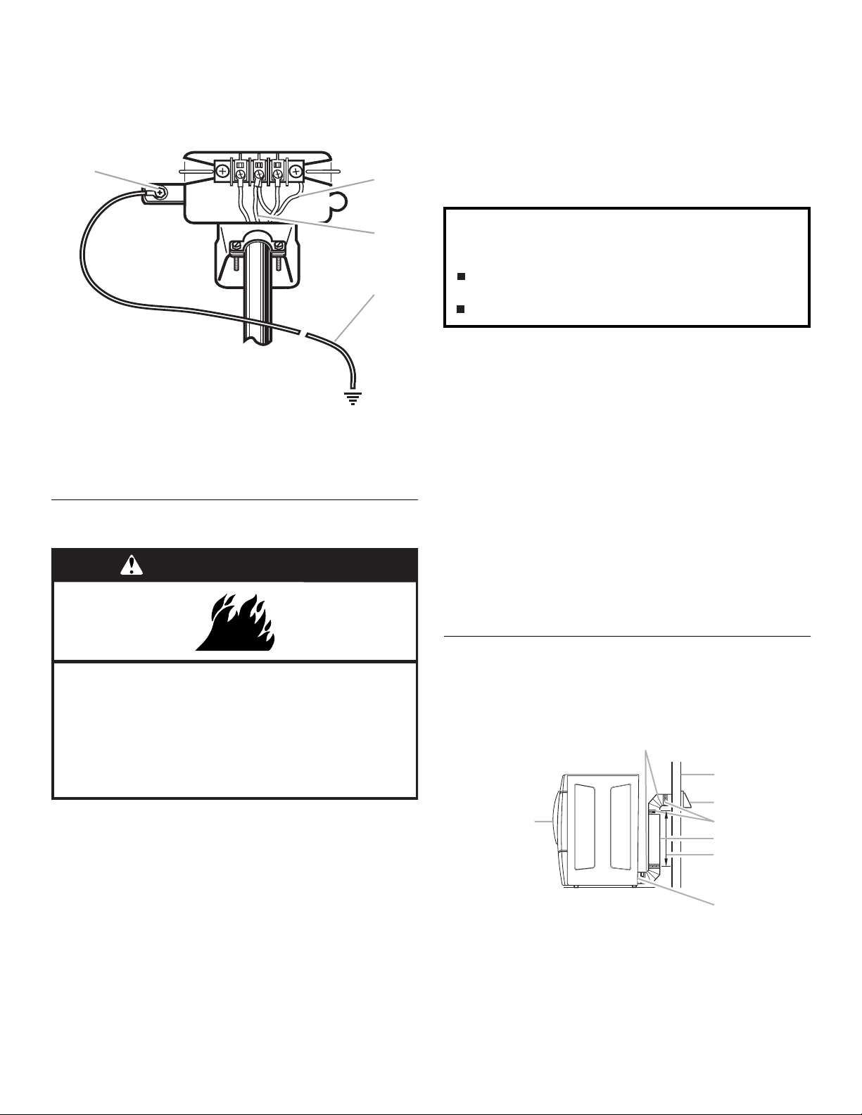
4. Apriete los tornillos del protector de cables.
D
5. Introduzca la lengüeta de la cubierta del bloque de terminal
en la ranura del panel posterior de la secadora. Asegure la
cubierta con el tornillo de sujeción.
6. Conecte un hilo de tierra de cobre separado desde el tornillo
conductor de tierra externo a tierra adecuada.
A
B
■ No use una capota de ventilación con pestillo magnético.
■ No instale el ducto de escape de metal flexible en paredes,
techos o pisos encerrados.
■ Utilice abrazaderas para sellar todas las juntas. No debe
conectarse ni asegurarse el ducto de escape con tornillos ni
con ningún otro dispositivo que se extienda hacia el interior
de dicho ducto. No utilice cinta para conductos.
IMPORTANTE: Observe todas las normas y ordenanzas
vigentes.
C
A. Tornillo conductor de tierra externo
B. Hilo neutro de puesta a tierra (verde con rayas amarillas)
C. Hilo neutro (hilo blanco o central)
D. Camino de puesta a tierra determinado por un
electricista capacitado
Requisitos deventilación
ADVERTENCIA
La ventilación inadecuada puede ocasionar la
acumulación de humedad y pelusa en la casa, lo cual
puede dar como resultado:
Daños de humedad en la carpintería, muebles, pintura,
empapelado, alfombras, etc.
Problemas en la limpieza de la casa y de salud.
Use un ducto de escape de metal pesado. No use un ducto de
escape de plástico ni de hoja de aluminio.
Se recomienda el ducto de escape de metal rígido para evitar
que se aplaste o se tuerza.
El ducto de escape de metal flexible debe extenderse y
sostenerse por completo cuando la secadora esté en su
ubicación final. Quite el exceso del ducto de metal flexible para
evitar que se doble y se tuerza, lo cual podría dar lugar a una
reducción del flujo de aire y bajo rendimiento.
Una capota de ventilación debe tapar el ducto de escape para
evitar el ingreso de roedores e insectos a la casa.
La capota de ventilación debe estar por lo menos a 12" (30,5 cm)
de distancia del piso o de cualquier objeto que pudiese estar en el
trayecto del ducto de escape (como flores, rocas o arbustos, etc.).
Si se usa un sistema de ventilación existente, limpie la pelusa
que está a lo largo del sistema y asegúrese de que la capota de
ventilación no esté obstruida con pelusa. Reemplace cualquier
ducto de escape de plástico o de hoja de metal por uno de metal
rígido o de metal flexible.
Peligro de Incendio
Use un ducto de escape de metal pesado.
No use un ducto de escape de plástico.
No use un ducto de escape de aluminio.
No seguir estas instrucciones puede ocasionar
la muerte o incendio.
ADVERTENCIA: Para reducir el riesgo de incendio, esta
secadora DEBE VENTILARSE HACIA EL EXTERIOR.
Se debe usar un ducto de escape de metal pesado de
4" (10,2 cm) y abrazaderas. Los productos de ventilación
DURASAFE™ son recomendables.
Los productos de ventilación DURASAFE™ pueden adquirirse
con su distribuidor o llamando a Whirlpool Parts and Accessories
(Piezas y accesorios de Whirlpool). Para más información, vea la
sección “Ayuda o servicio técnico” de este manual.
■ La salida de la secadora no debe conectarse en ningún ducto
de escape de gas, chimenea, pared, techo o el espacio
oculto de un edificio.
Planificación delsistemade ventilación
Instalaciones típicas de escape
Las instalaciones típicas tienen la ventilación en la parte posterior
de la secadora. Otras instalaciones son posibles.
B
C
D
A
A. Secadora
B. Codo
C. Pared
D. Capota de ventilación
E. Abrazaderas
F. Ducto de escape de metal rígido o
de metal flexible
G. Longitud necesaria del ducto de
escape para conectar los codos
H. Salida de ventilación
E
F
G
H
36

Instalaciones opcionales de escape
Esta secadora puede ser adaptada con el escape hacia el lado
derecho, hacia el lado izquierdo o en la parte inferior. Póngase en
contacto con su distribuidor local para hacer convertir su
secadora.
ADVERTENCIA
Peligro de Incendio
Cubra los orificios de escape con uno de los juegos
siguientes:
279818 (blanco)
280028 (meteorito)
Comuníquese con su distribuidor local.
No seguir estas instrucciones puede ocasionar la
muerte, incendio, choque eléctrico, o lesiones graves.
■ Instalación de periscopio (Para usar si hay desacoplo entre el
ducto de escape de la pared y el ducto de escape de la
secadora):
Pieza número 4396037 – Desacoplo de 0" (0 cm) a
18" (45,72 cm)
Pieza número 4396011 – Desacoplo de 18" (45,72 cm) a
29" (73,66 cm)
Pieza número 4396014 – Desacoplo de 29" (73,66 cm) a
50" (127 cm)
Previsiones especiales para las instalaciones en casas
rodantes
El ducto de escape deberá sujetarse firmemente en un lugar no
inflamable de la estructura de la casa rodante y no debe terminar
debajo de la casa rodante. El ducto de escape debe terminar en
el exterior.
A
A. Instalación estándar con desviación de la ventilación en la
parte posterior
B. Instalación de ventilación lateral a la izquierda o a la derecha
C. Instalación de ventilación inferior (no es una opción para
instalaciones de pedestal)
B
C
Instalaciones alternas para espacios limitados
Los sistemas de ventilación vienen en una amplia gama.
Seleccione el tipo más apropiado para su instalación. A
continuación se ilustran dos tipos de instalación para espacios
limitados. Consulte las instrucciones del fabricante.
AB
A. Instalación en la parte superior (también está disponible
con un codo de desviación)
B. Instalación de periscopio
NOTA: Se pueden adquirir los siguientes juegos para
instalaciones alternas en espacios limitados. Para obtener más
información, sírvase referirse a la sección “Ayuda o servicio
técnico” de este manual.
■ Instalación en la parte superior:
Pieza número 4396028
Cálculo de la longitud del ducto de escape
1. Seleccione la vía que proporcione el trayecto más recto y
directo al exterior. Planifique la instalación a fin de usar el
menor número posible de codos y vueltas. Cuando use los
codos o haga vueltas, deje todo el espacio que sea posible.
Doble el ducto de escape gradualmente para evitar que se
retuerza. Evite vueltas de 90º en la medida de lo posible.
mejor
2. Determinación de la longitud del ducto de escape.
La longitud máxima del sistema de ventilación depende de:
■ El tipo de ducto de escape (metal rígido o metal flexible).
■ El número de codos utilizados.
■ Tipo de capota de ventilación.
Los estilos recomendados de capotas de ventilación se
ilustran aquí.
A
4"
(10,2 cm)
A. Estilo de capota de ventilación tipo persiana
B. Estilo de capota de ventilación tipo caja
bien
B
4"
(10,2 cm)
37

El estilo de capota de ventilación angular (que se ilustra a
continuación) es aceptable.
4"
(10,2 cm)
2½"
(6,4 cm)
Vea el cuadro de longitudes de ducto de escape que vaya de
acuerdo con su tipo de capota de ventilación para fijarse en
las longitudes máximas del ducto de escape que usted
puede usar.
Los sistemas de ventilación más largos que los
especificados:
■ Acortarán la vida útil de la secadora.
■ Reducirán el rendimiento, dando lugar a tiempos de
secado más largos y un aumento en el consumo de
energía.
3. Determine el número de codos que va a necesitar.
IMPORTANTE: No use tendidos de ducto de escape más
largos que los especificados en el cuadro de longitudes de
ductos de escape.
El siguiente cuadro de longitudes de ducto de escape le
ayudará a determinar la longitud máxima del ducto, de
acuerdo con el número de vueltas de 90° o codos que
necesitará y con el tipo de ducto (metal rígido o metal
flexible) y capota que va a usar.
Cuadro de longitudes de ducto de escape
No. de
vueltas
de 90º
o
codos
Tipo de
ducto de
escape
Capotas de
ventilación de
caja o tipo
persianas
Capotas de
ventilación
angulares
Instalación delsistema deventilación
1. Instale la capota de ventilación. Emplee una masilla de
calafateo para sellar la abertura de la pared externa alrededor
de la capota de ventilación.
2. Conecte el ducto de escape a la capota de ventilación. El
ducto de escape debe encajar dentro de la capota de
ventilación. Asegure el ducto de escape a la capota de
ventilación con una abrazadera de 4" (10,2 cm).
3. Extienda el ducto de escape a la ubicación de la secadora.
Use la trayectoria más recta posible. Vea “Cálculo de la
longitud del ducto de escape”. Evite giros de 90º. Use
abrazaderas para sellar todas las juntas. No use cinta
adhesiva para conductos, tornillos ni otros dispositivos de
fijación que se extiendan dentro del ducto de escape, para
fijar el mismo.
Instalación delas patasniveladoras
ADVERTENCIA
Peligro de Peso Excesivo
Use dos o más personas para mover e instalar
la secadora.
No seguir esta instrucción puede ocasionar una
lesión en la espalda u otro tipo de lesiones.
1. Para proteger el piso, use un pedazo grande y plano de
cartón del empaque de la secadora. Coloque el cartón
debajo del borde posterior de la secadora. Vea la ilustración.
2. Sujete con firmeza el cuerpo de la secadora (no el panel de la
consola). Coloque la secadora cuidadosamente sobre el
cartón.
0 Metal rígido
Metal flexible
1 Metal rígido
Metal flexible
2 Metal rígido
Metal flexible
3 Metal rígido
Metal flexible
4 Metal rígido
Metal flexible
NOTA: Las instalaciones de ventilación laterales e inferiores
tienen una vuelta de 90º dentro de la secadora. Para determinar
la longitud máxima de ventilación, agregue una vuelta de 90º al
cuadro.
64 pies (20 m)
36 pies (11 m)
54 pies (16,5 m)
31 pies (9,4 m)
44 pies (13,4 m)
27 pies (8,2 m)
35 pies (10,7 m)
25 pies (7,6 m)
27 pies (8,2 m)
23 pies (7 m)
58 pies (17,7 m)
28 pies (8,5 m)
48 pies (14,6 m)
23 pies (7 m)
38 pies (11,6 m)
19 pies (5,8 m)
29 pies (8,8 m)
17 pies (5,2 m)
21 pies (6,4 m)
15 pies (4,6 m)
3. Examine las patas niveladoras. Localice la marca en forma de
diamante.
4. Atornille con la mano las patas en cada orificio de las patas.
Use una llave de tuercas para terminar de atornillar las patas
hasta que la marca en forma de diamante no quede visible.
5. Coloque un esquinal de cartón debajo de cada una de las 2
esquinas posteriores de la secadora. Ponga la secadora en
pie. Deslícela sobre los esquinales hasta que esté cerca de
su ubicación final. Deje suficiente espacio para conectar el
ducto de escape.
6. Una vez que la conexión esté lista y la secadora se encuentre
en su ubicación final, quite los esquinales y el cartón.
38

Nivelación dela secadora
C
Revise la nivelación de la secadora. Verifique primero de lado a
lado y luego del frente hacia atrás.
Si la secadora no está nivelada, apuntale la secadora, usando un
bloque de madera. Use una llave de tuercas para regular las
patas hacia arriba o hacia abajo y verifique nuevamente si la
secadora está nivelada.
NOTA: Quizás sea necesario nivelar la secadora nuevamente
después de trasladarla a su ubicación final.
Conexión del ducto deescape
1.
Usando una abrazadera de 4" (10,2 cm), conecte el ducto de
escape a la salida de aire de la secadora. Si se conecta a un
ducto de escape existente, asegúrese de que el mismo esté
limpio. El ducto de escape de la secadora debe encajar sobre
la salida de aire de la secadora y dentro de la capota de
ventilación. Cerciórese de que el ducto de escape esté
asegurado a la capota de ventilación con una abrazadera de
4" (10,2 cm).
2. Mueva la secadora a su posición final. No aplaste ni retuerza
el ducto de escape. Asegúrese de que la secadora esté
nivelada.
3. (En modelos a gas) Asegúrese de que no hayan torceduras
en la línea de gas flexible.
3. Coloque la puerta de la secadora sobre una superficie plana
y protegida con el ensamblaje interior de la puerta mirando
hacia arriba. Quite el último tornillo del paso 1. Quite los
2 tornillos que sujetan la agarradera a la puerta.
4. Quite los 6 tornillos para liberar el ensamblaje exterior de la
puerta del ensamblaje interior de la puerta (vea la ilustración).
Es importante que quite solamente los 6 tornillos indicados.
5. Levante el ensamblaje interior de la puerta y sáquelo del
ensamblaje exterior de la puerta. Desenganche la manija del
ensamblaje exterior de la puerta, muévalo hacia el otro lado y
engánchelo. Coloque a un lado el ensamblaje exterior de la
puerta.
Cómo invertirelcierre dela puerta
Usted puede invertir el cierre de la puerta de la abertura a la
derecha a la abertura a la izquierda, si lo desea.
Cómo quitar la puerta
1. Abra la puerta de la secadora. Quite los 4 tornillos que
sostienen la bisagra de la puerta sobre el panel frontal de la
secadora. Afloje el tornillo que tiene la abertura superior de la
llave por último (el segundo de la parte superior), pero no lo
quite.
A
B
A. Secadora
B. No lo quite
C. Puerta de la secadora
2. Levante y jale la puerta hacia adelante de manera que el ojo
de la cerradura despeje la cabeza del tornillo. Quite la puerta.
Cómo invertir la bisagra y el soporte de la bisagra
1. Coloque la puerta interior sobre la superficie de trabajo con la
cabeza del tornillo mirando hacia arriba.
2. Quite los 4 tornillos que sujetan la bisagra a la puerta.
39

3. Quite los 2 tornillos que sujetan el soporte de la agarradera a
B
C
la puerta.
4. Mueva la bisagra hacia el otro lado y vuelva a sujetarla con
los 4 tornillos que quitó en el paso 2.
5. Mueva el soporte de la agarradera hacia el otro lado y vuelva
a sujetarlo con los 2 tornillos que quitó en el paso 3.
6. Deje a un lado el ensamblaje interior de la puerta.
Cómo volver a instalar la puerta
1. Fíjese si hay huellas digitales en el vidrio. Límpielas si es
necesario.
2. Coloque el ensamblaje interior de la puerta dentro del
ensamblaje exterior de la puerta. Alinee la bisagra con la
abertura lateral. Para que encaje correctamente, el borde del
ensamblaje interior de la puerta está completamente dentro
del borde del ensamblaje exterior de la puerta.
3. Vuelva a colocar los ensamblajes interior y exterior de la
puerta con los 6 tornillos.
4. Vuelva a colocar los 2 tornillos para la manija del ensamblaje
de la puerta.
5. Use un pequeño destornillador de hoja plana para quitar los
tapones de los orificios en la abertura de la puerta. Deslice la
cabeza del destornillador debajo de la tapa de cada tapón,
siendo cuidadoso de no rayar la superficie de la secadora.
Levántela. Repita el proceso en el medio y en la parte inferior.
Quite la cinta de tapón en la abertura de la puerta e insértela
en el lado opuesto
6. Inserte un tornillo en la segunda abertura de la parte superior
de la abertura de la bisagra y apriete parcialmente. Cuelgue
la puerta colocando el ojo de la cerradura de la bisagra
superior sobre la segunda cabeza de tornillo y apriete el
tornillo.
Colocando primero este tornillo, la puerta permanecerá en su
lugar mientras usted inserta y aprieta los 4 tornillos restantes.
A
A. Puerta de la secadora
B. Secadora
C. Inserte primero este tornillo
7. Cierre la puerta y fíjese que se cierre con seguridad.
Complete lainstalación
1. Revise para cerciorarse de que todas las piezas estén
instaladas. Si hay alguna pieza extra, vuelva a revisar todos
los pasos para ver cuál se omitió.
2. Verifique si tiene todas las herramientas.
3. Deshágase de todos los materiales de embalaje o recíclelos.
4. Revise la localización final de la secadora. Asegúrese de que
el ducto de escape no esté aplastado o retorcido.
5. Verifique si la secadora está nivelada. Vea “Nivelación de la
secadora”.
6. Enchufe en un contacto con conexión a tierra. Conecte el
suministro de energía.
7. Quite la película protectora azul que está en la consola y
cualquier cinta adhesiva que haya quedado en la secadora.
8. Lea “Uso de la secadora”.
9. Limpie el interior del tambor de la secadora meticulosamente
con un paño húmedo para quitar residuos de polvo.
10. Fije la secadora en un ciclo completo de calor (no el ciclo de
aire) y póngala a funcionar durante 20 minutos.
Si la secadora no funciona, revise lo siguiente:
■ Que los controles estén fijados en una posición de
funcionamiento u “On” (encendido).
■ Que se ha presionado con firmeza el botón de puesta en
marcha.
■ Que la secadora esté conectada en un contacto con
conexión a tierra.
■ Que el suministro eléctrico esté conectado.
■ Que el fusible de la casa esté intacto y ajustado, o que no
se haya disparado el cortacircuitos.
■ Que la puerta de la secadora esté cerrada.
11. Después de que la secadora haya estado funcionando
durante 5 minutos, abra la puerta y fíjese si está caliente.
Si no está caliente, apague la secadora y revise lo
siguiente:
■ Posiblemente hayan 2 fusibles o disyuntores para la
secadora. Revise para asegurarse de que ambos fusibles
estén intactos y ajustados, o que ambos disyuntores no
se hayan disparado. Si después de esto todavía no
calienta, póngase en contacto con un técnico
competente.
NOTA: Cuando caliente la secadora por primera vez quizás
sienta un olor a quemado. Este olor es común cuando se usa por
primera vez el elemento de calefacción. El olor desaparecerá.
40

USO DE LA SECADORA
Puestaen marcha de lasecadora
ADVERTENCIA
Peligro de Explosión
Mantenga los materiales y vapores inflamables, tales
como la gasolina, alejados de la secadora.
No seque ningún artículo que haya tenido alguna vez
cualquier substancia inflamable (aún despuésde
lavarlo).
No seguir estas instrucciones puede ocasionar
la muerte, explosión o incendio.
ADVERTENCIA
ADVERTENCIA: A fin de reducir el riesgo de incendio, de
choque eléctrico o de daños personales, lea las
INSTRUCCIONES IMPORTANTES DE SEGURIDAD antes de
operar este aparato.
La siguiente es una guía para poner su secadora en marcha. Por
favor consulte las secciones específicas de este manual para
obtener información más detallada.
1. Limpie el filtro de pelusa antes o después de cada ciclo. Vea
“Limpieza del filtro de pelusa”.
2. Coloque la ropa en la secadora y cierre la puerta. Vea “Cómo
cargar”.
3. Gire el selector para seleccionar un ciclo Manual o
Automático, luego presione el botón de control encendido
(CONTROL ON). Aparecerán en la pantalla los ajustes y el
tiempo de secado prefijados para el ciclo elegido.
Para usar un ciclo Automático
■ Dirija el selector hacia un ciclo Automático.
■ Seleccione el nivel de sequedad (DRYNESS LEVEL) para
ajustar la sequedad de la carga según desee. El tiempo
que aparece en la pantalla es la duración estimada del
ciclo basada en el nivel de sequedad seleccionado. A
medida que el ciclo funciona, el control detecta la
sequedad de la carga y ajusta el tiempo automáticamente
para el nivel de sequedad seleccionado.
Peligro de Incendio
Ninguna lavadora puede eliminar completamente
el aceite.
No seque ningún artículo que haya tenido alguna vez
cualquier tipo de aceite (incluyendo los aceites de
cocina).
Los artículos que contengan espuma, hule o plástico
deben secarse en un tendedero o usando un
Ciclo de Aire.
No seguir estas instrucciones puede ocasionar
la muerte o incendio.
NOTA: No puede ajustarse el tiempo para los ciclos
automáticos. Al presionar los botones (- o +) de Tiempo de
secado manual, se escuchará un sonido triple de pitido que
indica que no puede cambiarse el tiempo.
■ Presione el botón de la característica Cuidado adicional
(EXTRA CARE) si desea esa opción.
■ Presione el botón de la señal de fin de ciclo (CYCLE END
SIGNAL) para fijar el volumen de la señal en el nivel deseado.
■ Presione (y sostenga) el botón de Sostenga para poner en
marcha (HOLD TO START) (por más o menos 1 segundo)
hasta que comience a funcionar la secadora.
Una vez que haya comenzado un ciclo Automático, podrán
ajustarse la característica Cuidado adicional y la señal de Fin
de ciclo. Presione dos veces el botón de Apagado (OFF) para
detener la secadora y despejar los ajustes, lo que le permitirá
seleccionar otro ciclo y nivel de sequedad.
41

Para usar un ciclo Manual
■ Gire el selector para seleccionar un ciclo Manual.
Presione los botones (- o +) de Tiempo de secado manual
(MANUAL DRY TIME) hasta que el tiempo de secado deseado
aparezca en la pantalla. Toque - o + y el tiempo cambiará en
intervalos de 1 minuto. Presione y sostenga - o + y el tiempo
cambiará en intervalos de 5 minutos. El tiempo que aparece
inicialmente en la pantalla es el tiempo real de secado.
NOTA: La característica de Tiempo de secado manual (Manual
Dry Time) puede ser usada sólo con ciclos manuales.
■ Presione Temperatura (TEMP) hasta que la temperatura
deseada se ilumine.
NOTA: El presionar el botón de nivel de sequedad causará un
sonido triple de pitido que indica que no puede seleccionarse
esa opción. Tampoco se indicará el nivel de sequedad.
■ Presione el botón de la característica Cuidado adicional
(EXTRA CARE) si desea esa opción.
■ Presione el botón de la señal de fin de ciclo (CYCLE END
SIGNAL) para fijar el volumen de la señal en el nivel deseado.
■ Presione (y sostenga) el botón de Sostenga para poner en
marcha (HOLD TO START) (más o menos por 1 segundo)
hasta que comience a funcionar la secadora.
Mientras esté funcionando un ciclo Manual, podrá cambiar los
ajustes de tiempo, temperatura, la característica de Cuidado
adicional y la señal de fin de ciclo. Presione dos veces el botón
de Apagado (OFF) para detener la secadora y despejar los
ajustes, lo que le permitirá seleccionar otro ciclo.
Detencióndelamarchadelasecadora
Para detener su secadora en cualquier momento
Presione OFF dos veces o abra la puerta.
Pausaoreanudacióndelamarcha
Para hacer una pausa en cualquier momento
Abra la puerta u oprima OFF una vez.
Para reanudar la marcha de la secadora
Cierre la puerta y presione (y sostenga) el botón de HOLD TO
START hasta que comience a funcionar la secadora.
NOTA: El secado continuará desde la etapa en que se
interrumpió el ciclo si usted cierra la puerta y presiona puesta en
marcha dentro de los 5 minutos siguientes. Si se interrumpe el
ciclo durante más de 5 minutos, la secadora se apagará.
Seleccione nuevos ajustes de ciclo antes de volver a poner la
secadora en marcha.
Control bloqueado
Esta característica le permite bloquear los ajustes para evitar el
uso accidental de la secadora. Asimismo puede usar la
característica Control bloqueado (Control Locked) para evitar
cambios accidentales de ciclo o de opción durante el
funcionamiento de la secadora.
Para activar la característica de control bloqueado cuando
esté funcionando la secadora:
Presione y sostenga el botón CYCLE END SIGNAL por
3 segundos. El control está bloqueado cundo se escucha un
solo pitido y está encendida la luz de control bloqueado.
■ Cuando esté apagada la secadora, no será necesario
presionar el botón de control encendido antes de activar la
característica de control bloqueado.
Para desbloquear:
Presione y sostenga el botón CYCLE END SIGNAL por tres
segundos para apagar esta característica.
NOTA: Cuando esté funcionando la secadora y esté encendido
Control bloqueado, podrá detenerse la secadora presionando el
botón de Apagado, pero no puede volver a comenzar hasta que
el control esté desbloqueado.
Cómo cargar
El cargar adecuadamente su secadora puede reducir sus gastos
de consumo de energía y prolongar la vida de sus prendas de
vestir.
Sugerencias para cargar
■ Cargue la secadora según la cantidad de espacio que
ocupan los artículos, no por su peso.
■ No sobrecargue la secadora. Esto da lugar a un secado
desigual y a la formación de arrugas.
Secadoras de capacidad superior “plus”
Ropa de trabajo pesado
4 pantalones de mezclilla
4 pantalones de trabajo
4 camisas de trabajo
Toa ll as
10 toallas de baño
10 toallas de mano
Carga mixta
3 sábanas (1 de cama doble,
2 de camas gemelas)
4 fundas
3 camisas
3 blusas
2 pantalones de deporte
2 camisetas de deporte
14 toallas faciales
9 camisetas
9 pantalones cortos
10 pañuelos
Sugerencias deciclos ysecado
Seleccione el ciclo y el nivel de sequedad o temperatura
correctos para su carga. Si está funcionando un ciclo
automático, la pantalla muestra el tiempo estimado del ciclo
cuando su secadora detecta automáticamente el nivel de
sequedad de su carga. Si está funcionado un ciclo manual, la
pantalla muestra el número exacto de minutos restantes en el
ciclo.
El enfriamiento (Cool Down) hace rotar la ropa sin calor durante
los últimos minutos de todos los ciclos. El enfriamiento hace que
las prendas se puedan manejar con más facilidad y reduce la
formación de arrugas. La duración del enfriamiento depende del
tamaño de la carga y el nivel de sequedad.
Sugerencias de secado
■ Siga las instrucciones de cuidado de la etiqueta cuando
estén disponibles.
■ Si desea, agregue una hoja de suavizante de telas. Siga las
instrucciones del paquete.
■ Quite la carga de ropa de la secadora tan pronto se detenga
la rotación para evitar que las prendas se arruguen. Esto es
de singular importancia para las prendas de planchado
permanente, tejidos de punto y fibras sintéticas.
■ Evite secar la ropa de trabajo gruesa junto con telas livianas.
Esto podría ocasionar un secado excesivo de las telas
livianas, dando lugar a un mayor encogimiento o formación
de arrugas de las mismas.
42

Sugerencias de ciclos
■ Seque la mayoría de las cargas usando los ajustes prefijados
de ciclos.
■ Consulte el cuadro de Ajustes de ciclos prefijados manuales
o de secado automático (en la sección “Ciclos”) a fin de
obtener una guía para el secado de diversas cargas de ropa.
■ La temperatura de secado y el nivel de secado
automático están prefijados cuando usted elije un ciclo
de secado automático. Usted puede seleccionar un nivel
de sequedad distinto, según su carga de ropa, al
presionar el botón de Nivel de sequedad (DRYNESS
LEVEL) para seleccionar Más (MORE) o Menos (LESS).
■ Si desea regular la duración de un ciclo manual, tiene que
presionar los botones de (- o +) del Tiempo de secado
manual (MANUAL DRY TIME). Ajuste la temperatura de
un ciclo manual presionando TEMP hasta que la
temperatura deseada esté seleccionada.
NOTA: Usted no puede elegir el Nivel de sequedad con ciclos
manuales.
Luces deestado
Con las luces indicadoras de secado puede vigilar el progreso de
su secadora.
Ciclo completo (Cycle Complete)
La luz de CYCLE COMPLETE se ilumina cuando se ha terminado
un ciclo. Si se ha seleccionado la característica Extra Care, la luz
indicadora del Cuidado adicional también estará encendida.
La luz indicadora de ciclo completo se apagará una hora
después de que termine el ciclo de secado (incluido el ciclo Extra
Care de 2 horas) cuando se presione apagado (Off) o cuando se
abra la puerta.
Característica Cuidado adicional (Extra Care)
La luz de la característica EXTRA CARE se enciende cuando se
selecciona esta opción. Este indicador permanece encendido
con la luz de ciclo completo.
Control bloqueado (Control Locked)
La luz de CONTROL LOCKED se enciende cuando se activa esta
opción.
Luces indicadoras
Otras luces indicadoras en el panel de control muestran los
ajustes seleccionados de Ciclo, Temperatura y Fin de ciclo.
La pantalla de tiempo indicará el tiempo restante estimado o real
en un ciclo.
Ciclos
Seleccione el ciclo de secado de acuerdo con el tipo de carga
que va a secar. (Vea los cuadros de Ajustes de ciclos prefijados
manuales o de secado automático.)
Detección (Sensing)
Cuando se inicie un ciclo por primera vez, se encenderá la luz de
SENSING hasta que se detecte un artículo húmedo.
■ En un ciclo Automático, si no se ha detectado un artículo
húmedo dentro de 10 minutos, la luz de detección y la
secadora se apagarán.
■ En un ciclo Manual, si no se detecta un artículo húmedo
después de 10 minutos, se iluminará la luz de Wet y
continuará el ciclo seleccionado.
Húmedo (Wet)
La luz de WET se encenderá cuando se haya detectado un
artículo húmedo en la secadora. La luz de húmedo permanecerá
encendida hasta que:
■ Se alcance el punto de casi seco en un ciclo Automático.
■ La secadora entre en el período de enfriamiento en un ciclo
Manual.
Casi seco (Damp)
La luz de DAMP indica que la carga ha alcanzado el nivel de casi
seco.
NOTA: La luz de Casi seco no se usa con los ciclos manuales.
Enfriamiento (Cool Down)
La luz de COOL DOWN se ilumina durante la porción de
enfriamiento del ciclo. La ropa se enfría para que sea más fácil
manipularla.
Perilla de control de ciclos
Ciclos automáticos
Los ciclos automáticos le permiten regular el ciclo según la carga
que va a secar. Vea el siguiente cuadro de Ajustes de ciclos
prefijados automáticos. Cada ciclo seca determinadas telas a la
temperatura recomendada. Un sensor detecta la humedad de la
carga y regula automáticamente el tiempo de secado para lograr
un secado óptimo.
Secado intenso (Heavy Duty)
Use este ciclo para obtener calor para artículos pesados como
toallas de algodón o cubrecamas.
Normal
Use este ciclo para obtener calor medio alto para secar telas
resistentes como ropa de trabajo.
Informal (Casual)
Use este ciclo para obtener calor medio para secar telas que no
necesitan planchado como camisas deportivas, ropa de oficina
informal y mezclas de planchado permanente.
43

Ropa delicada (Delicate)
Use este ciclo para obtener calor bajo para telas sintéticas, de
tejido de punto lavables y de acabado inarrugable.
Super delicado (Super Delicate)
Use este ciclo para obtener calor muy bajo para secar
cuidadosamente artículos como lencería, ropa de ejercicio o
cortinas muy finas.
Ajustes de ciclos prefijados automáticos
Ciclos automáticos
Tipo de carga
Secado INTENSO
(HEAVY DUTY)
Ropa pesada, toallas
NORMAL
Pantalones de pana, ropa
de trabajo
Temperatura Tiempo*
(Minutos)
Alta 40
Mediana 34
Ajustes de ciclos prefijados manuales
Ciclos manuales
Tipo de carga
Secado programado
(TIMED DRY)
Ropa pesada, ropa
voluminosa, cubrecamas,
ropa de trabajo
Retoque
(TOUCHUP)
Elimina las arrugas
Secado rápido
(RAPID DRY)
Cargas pequeñas
Temperatura Tiempo por
Alta 40
Mediana 20
Alta 27
omisión
(Minutos)
Informal (CASUAL)
Fibras de planchado
permanente, fibras
sintéticas
Ropa delicada
(DELICATE)
Lencería, blusas, artículos
lavables de lana
Super delicado
(SUPER DELICATE)
Ropa de ejercicio,
cortinas muy finas, encaje
*Tiempo estimado con el ajuste de Nivel de secado (Dryness
Level) (mediano).
Mediana 36
Baja 28
Muy baja 22
Ciclos manuales
Use los ciclos manuales para seleccionar una cantidad
específica de tiempo de secado y temperatura de secado. Al
seleccionar un ciclo manual, la pantalla de Tiempo estimado
restante (ESTIMATED TIME REMAINING) muestra el tiempo real
restante del ciclo. Usted puede cambiar el tiempo real del ciclo al
presionar los botones de (- o +) del tiempo de secado manual.
Secado programado (Timed Dry)
Use este ciclo para terminar el secado de artículos que todavía
están húmedos después de un ciclo Automático. El secado
programado es también útil para secar artículos pesados y
voluminosos como cubrecamas y ropa de trabajo.
Características adicionales
Característica de Cuidado adicional (Extra Care)
Si no es posible retirar la carga de la secadora tan pronto como
ésta se detenga, se pueden formar arrugas. La característica de
cuidado adicional da vueltas, reacomoda y esponja
periódicamente la ropa para ayudar a reducir las arrugas.
■ Presione la característica de Extra Care para obtener hasta
un máximo de 120 minutos de rotación periódica sin calor al
final de un ciclo.
■ Deténgala en cualquier momento presionando la
característica Extra Care o abriendo la puerta de la secadora.
■ Para el ciclo Informal, la característica de Cuidado adicional
está prefijada en Encendido (“On”). Los otros ciclos
automáticos retendrán el ajuste de la característica de
Cuidado adicional. (Por ejemplo, si usted selecciona la
característica de Cuidado adicional en el ciclo Normal, la
característica de Cuidado adicional estará encendida la
próxima vez que seleccione el ciclo Normal.)
NOTA: Si usted no selecciona la característica de Extra Care, la
secadora se detiene después del período de enfriamiento.
Temperatura
Los ajustes de temperatura se usan con los ciclos manuales.
Presione Temperatura (TEMP) hasta que el ajuste deseado de
temperatura se ilumine. Los ajustes de temperatura no se
pueden usar con los ciclos automáticos.
Retoque (Touchup)
Use este ciclo para alisar las arrugas de ropa que ha estado
empacada en una valija o artículos que se han arrugado por
haber permanecido mucho tiempo en la secadora.
Secado rápido (Rapid Dry)
Use este ciclo para el secado de cargas pequeñas o cargas que
necesitan un tiempo de secado corto.
44

Sólo aire (Air Only)
Use el ciclo de Sólo aire para artículos que requieren secado sin
calor, tales como artículos de goma, plástico y tejidos sensibles
al calor. Este cuadro muestra ejemplos de artículos que pueden
secarse usando el ciclo de sólo aire.
Tipo de carga Tiempo*
Goma espuma - almohadas, brasieres
acolchados, juguetes de peluche
Plástico - cortinas de ducha, manteles 20 - 30
Alfombras con reverso de goma 40 - 50
(Minutos)
20 - 30
Estantedesecado
El estante de secado es útil para secar a máquina artículos que
usted no quiere secar necesariamente con rotación o que
colgaría en el tendedero (por ejemplo, suéteres).
Para usar el estante de secado
No quite el filtro de pelusa.
1. Abra la puerta de la secadora.
Olefina, polipropileno, nailon diáfano 10 - 20
*Vuelva a fijar el tiempo para terminar el secado, si es necesario.
Cuando use Sólo aire
■ Revise para ver si las cubiertas están debidamente cosidas.
■ Sacuda y ahueque las almohadas a mano periódicamente
durante el ciclo.
■ Seque el artículo por completo. Las almohadas de goma
espuma tardan en secar.
NOTA: Los ciclos automáticos no están disponibles cuando se
esté usando el ajuste de Sólo aire.
Alarma de Fin de Ciclo (Cycle End Signal)
La señal de fin de ciclo emite un sonido audible una vez que el
ciclo de secado ha terminado. El quitar la ropa con prontitud al
final del ciclo reduce la formación de arrugas.
A
A. Borde anterior
2. Coloque el estante de secado dentro del tambor de la
secadora, colocando el alambre posterior sobre la saliente
del panel posterior del interior de la secadora. Empuje hacia
abajo sobre el borde anterior del estante de secado para
asegurarlo sobre el filtro de pelusa.
A
A. Panel posterior de la secadora
3. Ponga los artículos mojados sobre el estante de secado. Deje
espacio entre los artículos para que el aire pueda llegar a
todas la superficies.
NOTA: No permita que los artículos se cuelguen del borde del
estante.
Presione y suelte CYCLE END SIGNAL para regular el nivel de
sonido o para apagar la señal.
NOTA: Siempre que se seleccione la característica de Extra Care
y la señal de fin de ciclo esté encendida, se escuchará un sonido
audible cada 5 minutos hasta que se saque la ropa, o se termine
la acción de Cuidado adicional.
4. Cierre la puerta.
5. Seleccione el ciclo de secado programado y la temperatura,
o un ciclo de aire (vea el cuadro a continuación). Los artículos
que contengan espuma, hule o plástico deben secarse en un
tendedero o usando el ajuste de temperatura de sólo aire
(Air Only).
6. Usted debe seleccionar un tiempo, presionando los botones
de (- o +) del Tiempo de secado manual (MANUAL DRY
TIME). Vuelva a fijar el tiempo para terminar el secado, si es
necesario. Consulte el cuadro a continuación.
7. Presione (y sostenga) el botón de Sostenga para poner en
marcha (HOLD TO START) (por aproximadamente
1 segundo).
NOTA: Usted debe quitar el estante para un secado normal. No
use ciclos automáticos con el estante de secado.
45

Este cuadro muestra ejemplos de artículos que pueden secarse
en el estante y el tiempo sugerido de secado, ciclo y el ajuste de
temperatura. El tiempo real de secado dependerá de la cantidad
de humedad en la carga.
Secado con estante Ajuste Temp. Tiempo*
Suéteres de lana
Darles la forma original y
colocarlos extendidos sobre
el estante de secado
Juguetes de peluche o
almohadas
Rellenos de fibras de
algodón o poliéster
Secado
programado
Secado
programado
Baja 60
Baja 60
Limpieza delfiltro depelusa
Limpieza de cada carga
El filtro de pelusa está localizado en la abertura de la puerta de la
secadora. Límpielo antes o después del secado de cada carga.
Un filtro obstruido con pelusa puede aumentar el tiempo de
secado.
Para limpiar
1. Jale el filtro de pelusa en sentido recto hacia arriba. Quite la
pelusa del filtro enrollándola con sus dedos. No enjuague ni
lave el filtro para quitar la pelusa. La pelusa mojada es difícil
de quitar.
Juguetes de peluche o
almohadas
Rellenos con hule espuma
Zapatos tenis o zapatos
de lona
*(Minutos) Vuelva a fijar el ciclo para terminar el secado, si es
necesario.
Secado
programado
Secado
programado
Sólo aire
(sin
calor)
Sólo aire
(sin
calor)
90
90
CUIDADO DE LA
SECADORA
Limpieza dellugar donde estála secadora
Mantenga el área donde está la secadora despejada y libre de
artículos que pudieran obstruir el flujo de aire para la combustión
y la ventilación.
ADVERTENCIA
Peligro de Explosión
Mantenga los materiales y vapores inflamables, como
la gasolina, lejos de la secadora.
Coloque la secadora a un mínimo de 46 cm sobre
el piso para la instalación en un garaje.
No seguir estas instrucciones puede ocasionar
la muerte, explosión o incendio.
2. Empuje el filtro de pelusa firmemente de vuelta en su lugar.
IMPORTANTE:
■ No ponga a funcionar la secadora con un filtro de pelusa
flojo, dañado, obstruido o sin él. El hacerlo puede causar un
sobrecalentamiento y dañar tanto la secadora como la ropa.
■ Algunas toallas hechas de fibras sintéticas y fibras naturales
(mezclas de poliéster y algodón) pueden soltar más pelusa
que otras toallas, dando lugar a que el filtro de pelusa de su
secadora se llene con más rapidez. Asegúrese de quitar la
pelusa del filtro de pelusa antes y después de secar toallas
nuevas.
■ Si al quitar la pelusa del filtro, ésta cae en la secadora, revise
la capota de ventilación y quite la pelusa. Vea “Requisitos de
ventilación”.
Limpieza según la necesidad
Los residuos de detergente de lavandería y suavizante de tejidos
pueden acumularse en el filtro de pelusa. Esta acumulación
puede ocasionar tiempos de secado más prolongados para su
ropa, o hacer que la secadora se detenga antes que su carga
esté completamente seca. Si la pelusa se cae del filtro cuando
éste está en la secadora, es probable que el filtro esté obstruido.
Limpie el filtro de pelusa con un cepillo de nailon cada 6 meses o
con más frecuencia si se obstruye debido a la acumulación de
residuos.
Para lavar
1. Quite la pelusa del filtro enrollándola con sus dedos.
2. Moje ambos lados del filtro de pelusa con agua caliente.
3. Moje un cepillo de nailon con agua caliente y detergente
líquido. Refriegue el filtro de pelusa con el cepillo para quitar
la acumulación de residuos.
46
4. Enjuague el filtro con agua caliente.
5. Seque meticulosamente el filtro de pelusa con una toalla
limpia. Vuelva a colocar el filtro en la secadora.

Limpiezadelinteriordelasecadora
Para limpiar el tambor de la secadora
1. Haga una pasta con un detergente de lavandería en polvo y
agua tibia.
2. Aplique la pasta a un paño suave.
O
Aplique al área manchada un producto de limpieza
doméstico líquido, no inflamable y frótelo con un paño suave
hasta quitar todo el exceso de tinte y manchas.
3. Limpie el tambor meticulosamente con un paño húmedo.
4. Ponga a funcionar la secadora con una carga de ropa limpia
o toallas para secar el tambor.
NOTA: Las prendas que contienen tintes desteñibles, tales como
los pantalones de mezclilla o artículos de algodón de colores
vivos, pueden teñir el interior de la secadora. Estas manchas no
dañan su secadora y no mancharán las cargas de ropa futuras.
Seque al revés los artículos que destiñen para evitar la
transferencia de tintes.
Eliminación depelusa acumulada
En el interior del gabinete de la secadora:
Según el uso de la secadora, se debe quitar la pelusa cada
2años, o con más frecuencia. La limpieza deberá efectuarla
una persona calificada.
En el ducto de escape:
La pelusa debe ser quitada nuevamente cada 2 años, o con más
frecuencia, de acuerdo con el uso de la secadora.
Cuidado paralas vacacionesy la mudanza
Cuidado para las vacaciones
Ponga la secadora a funcionar sólo cuando esté en casa. Si va a
salir de vacaciones o no va a usar su secadora por un tiempo
prolongado, usted deberá:
1. Desenchufar la secadora o desconectar el suministro de
energía.
2. Limpiar el filtro de pelusa. Vea “Limpieza del filtro de pelusa”.
Cuidado para la mudanza
ADVERTENCIA
Peligro de Choque Eléctrico
Desconecte el suministro de energía antes de darle
mantenimiento.
Vuelva a colocar todos los componentes y paneles
antes de hacerlo funcionar.
No seguir estas instrucciones puede ocasionar
la muerte o choque eléctrico.
1. Desenchufe la secadora o desconecte el suministro de
energía. Desconecte el cable si la secadora está conectada
por cableado directo.
2. Asegúrese de que las patas niveladoras estén fijas en la base
de la secadora.
3. Use cinta adhesiva para asegurar la puerta de la secadora.
Cambio dela luz deltambor
La luz de la secadora se enciende automáticamente en el interior
del tambor de la secadora cuando usted abre la puerta.
Para cambiar la luz del tambor
1. Desenchufe la secadora o desconecte el suministro de
energía.
2. Abra la puerta de la secadora. Localice la cubierta del foco
de luz en la pared posterior de la secadora. Quite el tornillo
ubicado en la esquina inferior derecha de la cubierta. Quite la
cubierta.
3. Gire el foco en sentido contrario a las manecillas del reloj.
Reemplácelo únicamente con un foco para
electrodomésticos de 10 W. Vuelva a colocar la cubierta en
su lugar y asegúrela con un tornillo.
4. Enchufe la secadora o reconecte el suministro de energía.
47

SOLUCIÓN DE PROBLEMAS
Pruebe primero las soluciones aquí sugeridas y posiblemente se evite el costo de una visita de servicio técnico…
La secadora muestra en la pantalla mensajes
codificados
■ “PF” (corte de energía), revise lo siguiente:
¿Se ha interrupido el ciclo de secado por un corte de
energía?
Presione (y sostenga) el botón de Sostenga para poner en
marcha (HOLD TO START) para reanudar la marcha de la
secadora.
■ “E” Códigos de servicio técnico variables (E1, E2, E3):
Solicite servicio técnico.
La ropa no se está secando bien
■ Revise lo siguiente:
¿Está obstruido el filtro de pelusa?
¿Está obstruido con pelusa el ducto de escape o la capota
de ventilación, restringiendo el flujo del aire? Ponga a
funcionar la secadora entre 5 a 10 minutos. Ponga su mano
debajo de la capota de ventilación para verificar el
movimiento del aire. Si no siente el movimiento del aire,
limpie el sistema de ventilación de pelusas o reemplace el
ducto de escape con uno de metal pesado o de metal
flexible. Consulte las “Instrucciones de instalación”.
¿Está el ducto de escape aplastado o retorcido?
Reemplácelo con uno de metal pesado o de metal flexible.
Consulte las “Instrucciones de instalación”.
¿Se ha quemado el fusible o se ha disparado el
cortacircuitos? Las secadoras eléctricas usan 2 fusibles
domésticos o interruptores. El tambor puede estar rotando
pero la secadora no está calentando.
¿Se ha seleccionado un ciclo de secado al aire? Seleccione
el ciclo adecuado para los tipos de prendas que está
secando. Vea “Ciclos”.
¿Está terminando más rápido el ciclo automático? Es posible
que la carga no esté haciendo contacto con las bandas del
sensor electrónico. Nivele la secadora.
¿Están las hojas de suavizante de tejidos bloqueando la
rejilla? Use únicamente una hoja de suavizante de tejidos y
úsela sólo una vez.
■ ¿Está la secadora ubicada en una habitación cuya
temperatura es inferior a 45ºF (7ºC)?
Para el funcionamiento adecuado de los ciclos de la
secadora se necesitan temperaturas superiores a 45ºF (7ºC).
■ ¿Se ha usado agua fría para el enjuague? ¿Estaba la
carga muy mojada?
Espere tiempos de secado más prolongados para artículos
enjuagados en agua fría y para aquellos que retienen
humedad (fibras de algodón).
■
¿Es la carga muy grande y pesada para secar con rapidez?
Separe la carga para que rote con libertad.
La secadora no funciona
■ Revise lo siguiente:
¿Está enchufado el cable eléctrico?
¿Se ha quemado un fusible o se ha disparado el
cortacircuitos?
¿Se ha usado un fusible común? Use un fusible retardador.
¿Se ha cerrado con firmeza la puerta de la secadora? Si no
es así, la pantalla de tiempo se encenderá y se apagará.
¿Ha presionado con firmeza y sostenido Sostenga para
poner en marcha (HOLD TO START) por lo menos
1segundo?
¿Se ha seleccionado un ciclo?
Sonidos raros
■ ¿Ha estado la secadora sin uso por una temporada?
Si no se ha usado la secadora por una temporada, es posible
que se escuche un sonido fuerte durante los primeros
minutos de funcionamiento.
Pelusa en la ropa
■ ¿Está obstruido el filtro de pelusa?
Limpie el filtro de pelusa. Verifique si hay movimiento de aire.
■ ¿Se ha separado debidamente la carga?
Separe la ropa que suelta pelusa (toallas, felpilla) de la ropa
que atrae pelusa (pana, fibra sintética). También sepárela por
color.
■ ¿Está la carga demasiado grande o demasiado pesada?
Seque cargas más pequeñas de modo que la pelusa pueda
ser capturada por el filtro de pelusa.
■ ¿Se ha secado en exceso la carga?
Use los ajustes correctos para el tipo de carga. Vea “Ciclos”.
El secar en exceso puede ocasionar la electricidad estática
que atrae pelusa.
■ ¿Se ha dejado papel o tisú en los bolsillos?
■ ¿Se está confundiendo las motitas con la pelusa?
Las motitas (pelusas en la superficie de la ropa) son
ocasionadas por el uso y el lavado normal de la ropa.
Manchas en la carga o cambio de color
■
¿Se ha empleado adecuadamente el suavizante de tejidos?
Agregue hojas de suavizante de tejidos al comienzo del ciclo
cuando la carga está fría. No agregue hojas de suavizante de
tejidos a una carga caliente.
■ ¿Estaban sucios los artículos en el momento en que se
colocaron en la secadora?
Los artículos deben estar limpios antes de secarlos.
■ ¿Se han separado debidamente los artículos?
Separe la ropa de colores claros de la de colores oscuros.
Separe los artículos de colores sólidos de los que destiñen.
48

Ropa encogida
Olores
■ ¿Se ha sobrecargado la secadora?
Seque cargas más pequeñas que puedan rotar con libertad.
■ ¿Se ha secado en exceso la carga?
Verifique la etiqueta de cuidado del fabricante. Fije el ajuste
de la secadora de acuerdo al tipo de carga. Vea “Ciclos”.
Ropa arrugada
■ ¿Se ha sacado la ropa de la secadora al final del ciclo?
■ ¿Se ha sobrecargado la secadora?
Seque cargas más pequeñas que puedan rotar con libertad.
■ ¿Se ha secado en exceso la carga?
Verifique la etiqueta de cuidado del fabricante. Fije el ajuste
de la secadora de acuerdo al tipo de carga. Vea “Ciclos”.
AYUDA O SERVICIO TÉCNICO
Antes de solicitar ayuda o servicio técnico, por favor consulte la
sección “Solución de Problemas”. Esto le podría ahorrar el costo
de una visita de servicio técnico. Si considera que aún necesita
ayuda, siga las instrucciones que aparecen a continuación.
Cuando llame, tenga a mano la fecha de compra y el número
completo del modelo y de la serie de su electrodoméstico. Esta
información nos ayudará a atender mejor a su pedido.
Si necesita piezas de repuesto
Si necesita pedir piezas de repuesto, recomendamos que use
únicamente piezas especificadas de fábrica. Estas piezas
encajarán bien y funcionarán bien ya que están confeccionadas
con la misma precisión empleada en la fabricación de cada
electrodoméstico nuevo de KITCHENAID
Para encontrar piezas de repuesto especificadas de fábrica en su
localidad, llame a nuestro Centro de interacción del cliente o al
centro de servicio designado de su localidad.
Para ayuda o servicio técnico
Llame al Centro de interacción del cliente de KitchenAid sin
costo alguno al: 1-800-422-1230.
®
.
■ ¿Ha estado pintando, tiñendo o barnizando
recientemente el área donde se encuentra la secadora?
De ser así, ventile el área. Cuando los olores o humos se
hayan esfumado del área, vuelva a lavar y secar la ropa.
■ ¿Se está usando la secadora por primera vez?
El nuevo elemento calefactor eléctrico puede despedir un
olor. El olor desaparecerá después del primer ciclo.
Prendas deterioradas
■ Revise lo siguiente:
¿Se han dejado abiertos los zípers, broches a presión y
sujetadores con corchetes?
¿Se han atado los cordones y fajas para evitar que se
enreden?
¿Se han observado las instrucciones de cuidado de las
etiquetas?
¿Se han deteriorado los artículos antes del secado?
Nuestros consultores ofrecen asistencia con respecto a:
■ Características y especificaciones de nuestra línea completa
de electrodomésticos.
■ Información sobre instalación.
■ Procedimiento para el uso y mantenimiento.
■ Venta de accesorios y piezas para reparación.
■ Asistencia especializada para el consumidor (habla hispana,
problemas de audición, visión limitada, etc.).
■ Recomendaciones con distribuidores locales, compañías que
dan servicio y distribuidores de partes para reparación. Los
técnicos de servicio designados por KitchenAid están
entrenados para cumplir con la garantía del producto y
ofrecer servicio una vez que la garantía termine, en cualquier
lugar de los Estados Unidos.
Para localizar a una compañía de servicio designada por
KitchenAid en su área, también puede consultar la sección
amarilla de su guía telefónica.
Para obtener más asistencia
Si necesita asistencia adicional, puede escribir a KitchenAid con
sus preguntas o dudas a:
KitchenAid Brand Home Appliances
Customer Interaction Center
553 Benson Road
Benton Harbor, MI 49022-2692
Favor de incluir un número telefónico de día en su
correspondencia.
49

GARANTÍA DE LA SECADORA KITCHENAID
GARANTÍA TOTAL DE DOS AÑOS
Durante dos años a partir de la fecha de compra, siempre y cuando se dé a la secadora un uso y mantenimiento de conformidad con
las instrucciones adjuntas o provistas con el producto, KitchenAid pagará por las piezas de repuesto especificadas de fábrica y del
gasto del trabajo de reparación para corregir defectos en los materiales o en la mano de obra. El servicio deberá ser suministrado por
una compañía de servicio designada por KitchenAid.
®
GARANTÍA LIMITADA DEL TERCER AL QUINTO AÑO EN LOS TABLEROS DE CONTROL ELECTRÓNICOS,
Durante el tercer al quinto año desde la fecha de compra, cuando esta secadora sea operada y mantenida de acuerdo a las
instrucciones adjuntas o provistas con el producto, KitchenAid pagará por las piezas de repuesto especificadas de fábrica para los
siguientes componentes, para corregir defectos de material o de mano de obra: los tableros de control electrónicos, cualquier
componente eléctrico en los modelos eléctricos; cualquier quemador en los modelos a gas; reemplazo del motor.
GARANTÍA LIMITADA DEL TERCER AL DÉCIMO AÑO PARA EL TAMBOR DE LA SECADORA Y EL ENSAMBLAJE
Durante el tercer al décimo año desde la fecha de compra, cuando esta secadora sea operada y mantenida de acuerdo a las
instrucciones adjuntas o provistas con el producto, KitchenAid pagará por las piezas de repuesto especificadas de fábrica para el
tambor de la secadora y el ensamblaje de la parte superior/armario, si se oxidaran debido a defectos de material o de mano de obra.
KitchenAid no pagará por:
1. Visitas de servicio técnico para corregir la instalación de su secadora, incluyendo la ventilación. Se debe usar un ducto de escape
de metal pesado de 4" (10,2 cm). Refiérase a la sección de ventilación de este manual y a las Instrucciones de instalación.
2. Visitas de servicio técnico para enseñarle a usar su secadora, para cambiar fusibles domésticos, para corregir la instalación
eléctrica de la casa o volver a colocar los disyuntores, o para cambiar focos de luz que están al alcance del propietario.
3. Reparaciones cuando su secadora se use de un modo diferente al doméstico normal de una familia.
4. Daños causados por accidente, alteración, uso indebido, abuso, incendio, inundación, actos fortuitos, instalación incorrecta
(incluyendo, pero no limitado al uso de ductos de escape de plástico o de hoja de aluminio flexible), instalación que no sea de
conformidad con los códigos de electricidad y plomería locales, o el empleo de productos no aprobados por KitchenAid.
5. Piezas de repuesto o gastos de reparación para electrodomésticos que se empleen fuera de los Estados Unidos.
6. Recogida y entrega. Este producto está diseñado para ser reparado en el hogar.
7. Reparaciones de piezas o sistemas como resultado de modificaciones no autorizadas que se hayan efectuado en el
electrodoméstico.
8. Cualquier gasto de mano de obra durante los períodos de la garantía limitada.
EL COMPONENTE ELÉCTRICO, QUEMADOR A GAS Y MOTOR
DE LA PARTE SUPERIOR/ARMARIO
KITCHENAID NO SE RESPONSABILIZARÁ POR DAÑOS INCIDENTALES O CONSECUENTES.
Algunos estados no permiten la exclusión o limitación de daños incidentales o consecuentes, de modo que esta exclusión o limitación
quizás no le corresponda a usted. Esta garantía le otorga derechos legales específicos, y es posible que usted tenga también otros
derechos, los cuales varían de un estado a otro.
Esta garantía no tiene vigor fuera de los cincuenta Estados Unidos. Póngase en contacto con el distribuidor autorizado de
KitchenAid para determinar si corresponde otra garantía.
Si necesita servicio, vea primero la sección “Solución de problemas”. Podrá encontrar ayuda adicional al consultar la sección “Ayuda o
servicio técnico”, o al llamar a nuestro Centro de Interacción del Cliente al 1-800-422-1230 desde cualquier lugar de los EE.UU. o al
escribir a: KitchenAid Brand Home Appliances, Customer Interaction Center, 553 Benson Road, Benton Harbor, MI 49022-2692.
Guarde este libro y su comprobante de compra juntos para
referencia futura. Usted deberá proporcionar el comprobante
de la compra o una fecha de instalación para obtener
servicio bajo la garantía.
Escriba la siguiente información acerca de su secadora para
ayudarle mejor a obtener asistencia o servicio técnico si alguna
vez llegara a necesitarlo. Deberá tener a mano el número
completo del modelo y de la serie. Podrá encontrar esta
información en la etiqueta con el número de modelo y de serie,
ubicados en la cavidad interna superior de la puerta de la
secadora.
Nombre del distribuidor _________________________________________
Dirección_______________________________________________________
Número de teléfono _____________________________________________
Número de modelo _____________________________________________
Número de serie ________________________________________________
Fecha de compra _______________________________________________
6/04
50

SÉCURITÉ DE LA SÉCHEUSE
Votre sécurité et celle des autres est très importante.
Nous donnons de nombreux messages de sécurité importants dans ce manuel et sur votre appareil ménager. Assurez-vous de
toujours lire tous les messages de sécurité et de vous y conformer.
Voici le symbole d’alerte de sécurité.
Ce symbole d’alerte de sécurité vous signale les dangers potentiels de décès et de blessures graves à vous
et à d’autres.
Tous les messages de sécurité suivront le symbole d’alerte de sécurité et le mot “DANGER” ou
“AVERTISSEMENT”. Ces mots signifient :
Risque possible de décès ou de blessure grave si vous ne
DANGER
AVERTISSEMENT
Tous les messages de sécurité vous diront quel est le danger potentiel et vous disent comment réduire le risque de blessure et
ce qui peut se produire en cas de non-respect des instructions.
IMPORTANTES INSTRUCTIONS DE SÉCURITÉ
Pour réduire le risque d'incendie, de choc électrique ou de blessure lors de l'utilisation de
AVERTISSEMENT :
la sécheuse, il convient d'observer certaines précautions élémentaires dont les suivantes :
■ Lire toutes les instructions avant d'utiliser la sécheuse.
■ Ne pas placer des articles exposés aux huiles de cuisson
dans votre sécheuse. Les articles contaminés par des
huiles de cuisson peuvent contribuer à une réaction
chimique qui pourrait causer à la charge de s'enflammer.
■ Ne pas faire sécher dans la machine des articles qui ont
déjà été nettoyés, lavés, imbibés, ou tachés d'essence,
de solvants pour nettoyage à sec, d'autres substances
inflammables, ou de substances explosives puisqu'elles
dégagent des vapeurs qui peuvent provoquer un
incendie ou une explosion.
■ Ne pas permettre à des enfants de jouer sur ou à
l'intérieur de la sécheuse. Une surveillance étroite est
nécessaire lorsque la sécheuse est utilisée près d'eux.
■ Avant d'enlever la sécheuse du service ou la jeter, enlever
la porte du compartiment de séchage.
Ne pas mettre la main dans la sécheuse si le tambour est
■
en mouvement.
■
Ne pas installer ni entreposer la sécheuse où elle sera
exposée aux intempéries.
■ Ne pas jouer avec les commandes.
CONSERVEZ CES INSTRUCTIONS
suivez pas immédiatement les instructions.
Risque possible de décès ou de blessure grave si vous
ne suivez pas les instructions.
■ Ne pas réparer ni remplacer une pièce de la sécheuse ou
essayer d'en faire l'entretien à moins d'une recommandation
spécifique dans le guide d'utlilisation et d'entretien, ou
publiée dans les instructions de réparation par l'utilisateur
que vous comprenez et pouvez exécuter avec compétence.
■ Ne pas utiliser un produit assouplissant de tissu ou des
produits pour éliminer la statique à moins qu'ils ne soient
recommandés par le fabricant du produit assouplissant de
tissu ou du produit.
■ Ne pas utiliser la chaleur pour faire sécher des articles
fabriqués avec du caoutchouc mousse ou des matériaux
semblables.
■ Nettoyer le filtre à charpie avant et après chaque charge.
■ Ne pas laisser la charpie, la poussière, ou la saleté
s'accumuler autour du système d'évacuation ou autour de
l'appareil.
■ Un nettoyage périodique de l'intérieur de la sécheuse et du
conduit d'évacuation doit être effectué par une personne
qualifiée.
■ Voir les instructions d'installation pour les exigences de
liaison de l'appareil à la terre.
51

INSTRUCTIONS D'INSTALLATION
Outillage etpièces nécessaires
Rassembler les outils et pièces nécessaires avant de commencer
l’installation. Lire et suivre les instructions fournies avec les outils
indiqués ici.
■ Tournevis à lame plate
■ Clé à molette avec
ouverture jusqu’à
1" (2,5 cm) ou clé à
douille hexagonale (pour
ajuster les pieds de la
sécheuse)
■ Pince à dénuder (raccord
■ Niveau
■ Tournevis Phillips n° 2
Pièces fournies
Retirer les sachets de pièces du tambour de la sécheuse. Vérifier
que toutes les pièces de la liste sont présentes.
4 pieds de nivellement
REMARQUE : Ne pas utiliser les pieds de nivellement si la
sécheuse doit être installée sur un piédestal.
Pièces nécessaires
Consulter les codes locaux. Vérifier l'alimentation électrique et le
circuit d'évacuation existants. Voir “Spécifications électriques” et
“Exigences concernant l'évacuation” avant d'acheter les pièces.
■ Pour les installations à faible espacement entre
31,5" (80,01 cm) et 37" (93,98 cm), voir la section
“Planification du système d'évacuation” pour les exigences
d'évacuation.
■ Clapets d’évacuation
■ Pistolet à calfeutrage et
composé de calfeutrage
(pour l’installation d’un
nouveau circuit
d’évacuation)
■ Cisaille de ferblantier
(pour l’installation d’un
nouveau conduit)
Options
Piédestal
Installez-vous la sécheuse sur un piédestal? Vous pouvez
acheter un piédestal séparément pour cette sécheuse. Ce
piédestal ajoutera environ 13" (33 cm) à la hauteur de la
sécheuse pour une hauteur totale d'environ 51" (130 cm).
Piédestal facultatif
Pour commander, téléphoner au marchand chez qui vous avez
acheté votre sécheuse ou se référer à la section “Assistance ou
service” de ce manuel. Demander la pièce numéro LAB2700PMT
(météorite) ou LAB2700MQ0 (blanche).
Nécessaire de superposition
Prévoyez-vous superposer votre laveuse et votre sécheuse?
Pour ce faire, vous devrez acheter un nécessaire de
superposition.
Pour commander, téléphoner au marchand chez qui vous avez
acheté votre sécheuse ou se référer à la section “Assistance ou
service” de ce manuel. Demandez la pièce numéro 8541503.
Emplacement d’installation
AVERTISSEMENT
37"
(93,98 cm)
Les installations pour maison mobile nécessitent un système
d’évacuation en métal disponible à l’achat chez le marchand
chez qui vous avez acheté votre sécheuse. Pour plus de
renseignements, veuillez consulter la section “Assistance ou
service” de ce manuel.
52
Risque d'explosion
Garder les matières et les vapeurs inflammables, telle
que l’essence, loin de la sécheuse.
Placer la sécheuse au moins 46 cm (18 po) au-dessus
du plancher pour une installation dans un garage.
Le non-respect de ces instructions peut causer
un décès, une explosion ou un incendie.
Il vous faudra
■ Un emplacement avec un conduit d’évacuation à proximité.
Voir “Exigences concernant l’évacuation”.
■ Un circuit séparé de 30 ampères.
■ Une prise électrique avec liaison à la terre située à moins de
2pi (61 cm) de l’un des côtés de la sécheuse. Voir
“Spécifications électriques”.
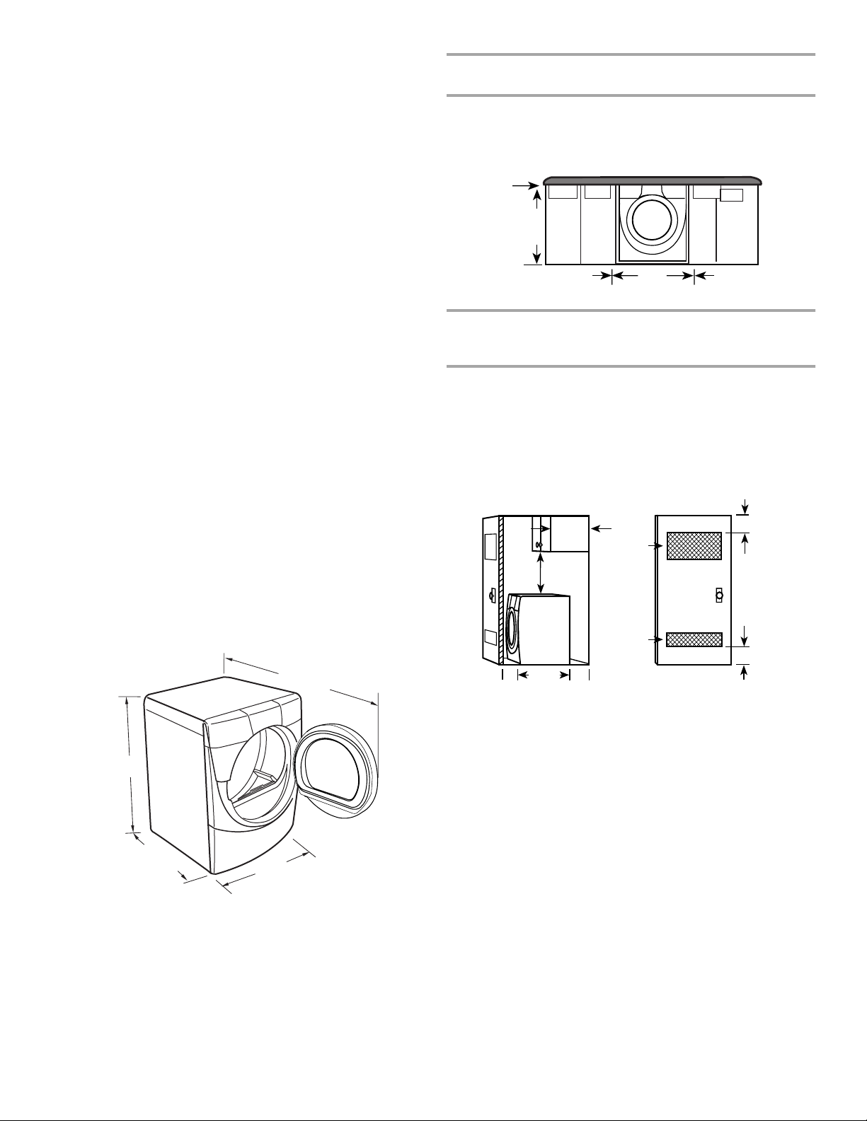
■ Un plancher robuste capable de soutenir le poids total de la
sécheuse de 200 lb (90,7 kg). Il faut aussi prendre en compte
le poids combiné d’un appareil ménager voisin.
■ Un plancher de niveau ayant une pente maximale de
1" (2,5 cm) sous l’ensemble de la sécheuse. Si la pente est
supérieure à 1" (2,5 cm), installer l'ensemble de pieds longs
pièce n° 279810. Si la sécheuse n'est pas d'aplomb, le linge
peut ne pas culbuter convenablement et les programmes
automatiques commandés par détecteur peuvent ne pas
fonctionner correctement.
■ Pour l’installation dans un garage, il faut placer la sécheuse à
au moins 18" (46 cm) au-dessus du sol. Si on utilise un
piédestal, il faudra ajouter 6" (15,24 cm) de plus.
Ne pas faire fonctionner la sécheuse à des températures
inférieures à 45ºF (7ºC). À des températures inférieures, la
sécheuse risque de ne plus s’arrêter à la fin d’un programme
automatique. Ceci risque de prolonger les durées de séchage.
La sécheuse ne doit pas être installée ou remisée dans un endroit
où elle sera exposée à l’eau et/ou aux intempéries.
Vérifier les règlements locaux. Certains codes limitent ou
n’autorisent pas l’installation des sécheuses dans un garage, un
placard, une maison mobile ou une chambre à coucher.
Communiquer avec l’inspecteur des bâtiments local.
Espacements d'installation
■ L’emplacement doit être assez grand pour permettre d’ouvrir
complètement la porte de la sécheuse.
■ On prévoira un peu plus d’espace pour faciliter l’installation
et l’entretien.
■ Un espace supplémentaire peut être requis pour les moulures
de porte et de plancher et pour les plinthes.
■ Un espace supplémentaire de 1" (2,5 cm) de tous les côtés
de la sécheuse est recommandé pour réduire le transfert du
bruit.
■ Il faut aussi prendre en compte l’espace requis entre les
appareils voisins.
Dimensions de la sécheuse
51½"
(130,81 cm)
38"
(96,52 cm)
Espacement minimum recommandé pour une
installation personnalisée sous un comptoir
Les dimensions indiquées sont pour l'espacement minimum
permis.
Installation personnalisée sous un comptoir - sécheuse
seulement
0"
(0 cm)
38" min.
(96,52 cm)
0"
(0 cm)
27"
(68,6 cm)
0"
(0 cm)
Espacement minimum pour une installation dans un
encastrement ou dans un placard, avec ou sans
piédestal
■ Les dimensions indiquées sont pour l’espacement minimum
permis.
■ Pour installation dans un placard avec porte, on doit prévoir
des ouvertures minimum d’entrée d’air en haut et en bas de
la porte. Les portes à claire-voie offrant des ouvertures
équivalentes de passage de l’air sont acceptables.
Installation dans un placard - Sécheuse seulement
3"
14" max.
(35,6 cm)
18" min.
(45,72 cm)
0"
31½"
(80 cm)
0"
(0 cm)
(0 cm)
A
A. Vue latérale - placard ou endroit exigu
B. Porte de placard avec orifices d’entrée d’air
48 po
(310 cm2)
24 po
(155 cm2)
2
2
B
(7,6 cm)
3"
(7,6 cm)
*31½"
(80 cm)
27"
(68,6 cm)
*La plupart des installations requièrent un espace minimum de
5½" (14 cm) derrière la sécheuse pour le conduit d’évacuation
avec coude. Voir “Exigences concernant l’évacuation”.
53

Installation dans un encastrement ou placard - sécheuse sur
piédestal
14" max.
(35,6 cm)
18" min.
(45,72 cm)
Spécifications électriques -
Canadaseulement
AVERTISSEMENT
0"
(0 cm)
27"
(68,6 cm)
0"
(0 cm)
0"
(0 cm)
31½"
(80 cm)
0"
(0 cm)
AB
A. Encastrement
B. Vue latérale - placard ou endroit exigu
Espacement minimum recommandé pour l'installation
de la caisse
■ Les dimensions indiquées sont pour l’espacement minimum
permis.
■ Pour installation de la caisse avec porte, on doit prévoir des
ouvertures minimum d’entrée d’air au sommet de la caisse.
7" (17,8 cm)
7" (17,8 cm)
9"
(22,9 cm)
Risque de choc électrique
Brancher sur une prise à 4 alvéoles reliée à la terre.
Le non-respect de cette instruction peut causer
un décès ou un choc électrique.
C’est à l’utilisateur qu’incombe la responsabilité de
■ Communiquer avec un électricien qualifié.
■ S'assurer que les connexions électriques sont adéquates et
conformes au Code canadien de l'électricité, C22.1 - dernière
édition et à tous les codes locaux. Pour obtenir un exemplaire
de la norme des codes ci-dessus, contacter : Association
canadienne de normalisation, 178 Rexdale Blvd., Toronto, ON
M9W 1R3 CANADA.
■ Alimenter l'appareil uniquement par un circuit monophasé de
115/230 volts CA, 60 Hz à 4 fils, sur un circuit séparé de
30 ampères, fusionné aux deux extrémités de la ligne. On
recommande l’emploi d’un fusible temporisé ou disjoncteur.
On recommande également que cet appareil soit alimenté
par un circuit indépendant.
■ Cette sécheuse est équipée d’un cordon électrique
homologué par la CSA International à introduire dans
une prise murale standard 14-30R. Le cordon mesure
5 pi (1,52 m). Veiller à ce que la prise murale se trouve à
proximité de l’emplacement définitif de la sécheuse.
0"
(0 cm)
31¹₂"
(80,0 cm)
0"
(0 cm)
0"
(0 cm)
27"
(68,6 cm)
0"
(0 cm)
Exigences supplémentaires pour l’installation dans une
maison mobile
Cette sécheuse convient aux installations pour maison mobile.
L’installation doit être conforme à la norme canadienne sur les
maisons préfabriquées CAN/CSA-Z240 MH.
L'installation dans une maison mobile exige :
■ Un système d'évacuation en métal qui peut être acheté chez
votre marchand.
■ Il faut prendre des dispositions spéciales pour l’apport d’air
de l’extérieur dans la sécheuse. L’ouverture (telle qu’une
fenêtre à proximité) devrait être au moins deux fois plus
grande que l’ouverture de décharge de la sécheuse.
54
Prise murale à 4 fils 14-30R
■ Ne pas utiliser de cordon de rallonge.

Si on utilise un cordon d'alimentation de rechange, il est
recommandé d'utiliser le cordon d'alimentation de rechange
numéro de pièce 9831317. Pour plus d'information, veuillez
consulter les numéros de service qui se trouvent à la section
“Assistance ou service” de ce manuel.
INSTRUCTIONS DE LIAISON À LA TERRE
■
Pour une sécheuse reliée à la terre et connectée par
un cordon :
Cette sécheuse doit être reliée à la terre. En cas de mauvais
fonctionnement ou de panne, la liaison à la terre réduira le
risque de choc électrique en offrant au courant électrique un
acheminement d'évacuation de moindre résistance. Cette
sécheuse est alimentée par un cordon électrique comportant
un conducteur relié à la terre et une fiche de branchement
munie d'une broche de liaison à la terre. La fiche doit être
branchée sur une prise appropriée qui est bien installée et
reliée à la terre conformément à tous les codes et règlements
locaux.
On peut se procurer les produits d’évacuation DURASAFE™
auprès du marchand ou en téléphonant à Pièces et accessoires
Whirlpool. Pour plus de renseignements, voir la section
“Assistance ou service” de ce manuel.
■ Le système d’évacuation de la sécheuse ne doit pas être
connecté à une évacuation de gaz, une cheminée, un mur, un
plafond ou un vide dans le bâtiment.
■ Ne pas utiliser un clapet d’évacuation à fermeture
magnétique.
■ Ne pas installer le conduit flexible en métal dans les cavités
fermées des murs, plafonds ou planchers.
■ Utiliser des brides de serrage pour sceller tous les joints. Le
système d’évacuation ne doit pas être connecté ou fixé avec
des vis ou autres dispositifs de serrage qui se prolongent à
l’intérieur du conduit. Ne pas utiliser de ruban adhésif.
IMPORTANT : Respecter toutes les prescriptions des codes et
règlements en vigueur.
AVERTISSEMENT :
cet appareil au conducteur de liaison à la terre peut susciter
un risque de choc électrique. En cas de doute quant à la
qualité de liaison à la terre de la sécheuse, consulter un
électricien ou un technicien ou un personnel qualifié. Ne pas
modifier la fiche de branchement fournie avec la sécheuse;
si la fiche ne correspond pas à la configuration de la prise de
courant, demander à un électricien qualifié d'installer une
prise de courant appropriée.
Le raccordement incorrect de
CONSERVEZ CES INSTRUCTIONS
Exigences concernant l’évacuation
AVERTISSEMENT
Risque d’incendie
Utiliser un conduit d’évacuation en métal lourd.
Ne pas utiliser un conduit d’évacuation en plastique.
Ne pas utiliser un conduit d’évacuation en feuille
de métal.
Le non-respect de ces instructions peut causer
un décès ou un incendie.
Une mauvaise évacuation de l'air peut causer de
l'humidité et une accumulation de charpie à l'intérieur de
la maison qui peut causer :
Dommages par l'humidité aux boiseries, meubles, peinture,
papier-peint, tapis, etc.
Problèmes de nettoyage dans la maison et problèmes
de santé.
Utiliser un conduit métallique rigide. Ne pas utiliser un conduit de
plastique ou en feuille métallique.
On recommande d’utiliser un conduit métallique rigide pour
réduire les risques d’écrasement et de déformation.
Un conduit métallique souple doit être totalement déployé et
soutenu lorsque la sécheuse est à sa position finale. Enlever tout
excès de conduit souple pour éviter tout affaissement et
déformation susceptibles de réduire la capacité d’évacuation et
le rendement.
Terminer le conduit d’évacuation par un clapet de décharge pour
empêcher les rongeurs et insectes d’entrer dans l’habitation.
Le clapet de décharge doit être situé à au moins 12" (30,5 cm)
au-dessus du sol ou de tout objet se trouvant sur le trajet de l’air
humide rejeté (par exemple, fleurs, roches ou arbustes, etc.).
Lors de l’utilisation d’un système de décharge existant, nettoyer
et éliminer la charpie sur toute la longueur du système et veiller à
ce que le clapet de décharge ne soit pas obstrué par une
accumulation de charpie. Remplacer tout conduit de plastique ou
de feuille métallique par un conduit métallique rigide ou souple.
AVERTISSEMENT : Pour réduire le risque d’incendie,
cette sécheuse DOIT ÉVACUER L’AIR À L’EXTÉRIEUR.
Utiliser un conduit d’évacuation métallique robuste de
4" (10,2 cm) et des brides de fixation. Les produits d’évacuation
DURASAFE™ sont recommandés.
55

Planification dusystème d'évacuation
Installations typiques d’évacuation
Les installations typiques consistent à acheminer le conduit
d’évacuation à l’arrière de la sécheuse. D’autres installations sont
possibles.
B
C
D
A
E
F
G
H
A. Sécheuse
B. Coude
C. Mur
D. Clapet de décharge
E. Brides
F. Conduit métallique rigide ou souple
G. Longueur de conduit nécessaire pour
raccorder les coudes
H. Bouche de décharge
Installations d’évacuation facultatives
Cette sécheuse peut être convertie pour évacuer par le côté
droit, le côté gauche ou par le bas. Contactez votre marchand
local pour faire convertir la sécheuse.
AVERTISSEMENT
Autres installations où le dégagement est réduit
Il existe de nombreux systèmes d’évacuation. Choisir le système
qui convient le mieux à l’installation. Deux installations à
dégagement réduit sont illustrées. Consulter les instructions du
fabricant fournies avec le système d'évacuation.
AB
A. Installation au-dessus de la sécheuse (aussi disponible
avec un coude décalé)
B. Installation de périscope
REMARQUE : On peut acheter les trousses suivantes pour les
installations où le dégagement est réduit. Veuillez consulter la
section “Assistance ou service” de ce manuel pour passer une
commande.
■ Installation au-dessus de la sécheuse :
Pièce numéro 4396028
■ Installation de périscope (Pour utilisation en cas de non-
concordance de la bouche de décharge de la sécheuse avec
le clapet) :
Pièce numéro 4396037 – Non-concordance de
0" (0 cm) à 18" (45,72 cm)
Pièce numéro 4396011 – Non-concordance de
18" (45,72 cm) à 29" (73,66 cm)
Pièce numéro 4396014 – Non-concordance de
29" (73,66 cm) à 50" (127 cm)
Risque d’incendie
Recouvrir tous les orifices d’évacuation non utilisés
avec l’une des trousses suivantes :
279818 (blanche)
280028 (météorite)
Contacter votre marchand local.
Le non-respect de ces instructions peut causer
un décès, un incendie, un choc électrique ou une
blessure grave.
A
A. Acheminement standard du conduit d'évacuation par l’arrière
B. Acheminement du conduit d'évacuation par la gauche ou par
la droite
C. Acheminement du conduit d'évacuation par le bas (pas une
option avec les installations sur piédestal).
B
C
Dispositions spéciales pour les installations dans une
maison mobile
Le système d’évacuation doit être solidement fixé à une section
non combustible de la structure de la maison mobile et ne doit
pas se terminer en dessous de la maison mobile. Faire en sorte
que le système d’évacuation se termine à l’extérieur.
56

Détermination de la longueur du conduit
1. Choisir l’itinéraire d’acheminement vers l’extérieur qui sera le
plus direct et le plus rectiligne. Planifier l’installation pour
introduire le nombre minimal de coudes et changements de
direction. Si des coudes sont utilisés pour les changements
de direction, prévoir autant d’espace que possible. Plier le
conduit graduellement pour éviter de le déformer. Éviter les
changements de direction à 90º.
meilleur bon
Le tableau suivant vous aide à déterminer la longueur
maximale du conduit d'évacuation selon le nombre de
changements de direction à 90° ou coudes dont vous aurez
besoin et le type de conduit métallique (rigide ou souple) et
de clapet que vous utiliserez.
Tableau de longueur du conduit d’évacuation
Nombre de
changements
de direction
Type de
conduit
Clapets de
type boîte ou
à persiennes
Clapets
inclinés
à 90° ou
coudes
2. Déterminer la longueur du conduit.
La longueur maximale du circuit de décharge dépend de
plusieurs facteurs :
■ Le type de conduit (métal rigide ou souple).
■ Le nombre de coudes incorporés au circuit.
■ Le type de clapet.
Les styles de clapet recommandés sont illustrés ci-dessous.
B
A
4"
(10,2 cm)
4"
(10,2 cm)
A. Clapet à persiennes
B. Clapet de type boîte
Le clapet incliné (illustré ci-dessous) est acceptable.
4"
(10,2 cm)
0Métallique
64 pi (20 m)
58 pi (17,7 m)
rigide
Métallique
36 pi (11 m)
28 pi (8,5 m)
souple
1Métallique
54 pi (16,5 m)
48 pi (14,6 m)
rigide
Métallique
31 pi (9,4 m)
23 pi (7 m)
souple
2Métallique
44 pi (13,4 m)
38 pi (11,6 m)
rigide
Métallique
27 pi (8,2 m)
19 pi (5,8 m)
souple
3Métallique
35 pi (10,7 m)
29 pi (8,8 m)
rigide
Métallique
25 pi (7,6 m)
17 pi (5,2 m)
souple
4Métallique
27 pi (8,2 m)
21 pi (6,4 m)
rigide
Métallique
23 pi (7 m)
15 pi (4,6 m)
souple
REMARQUE : Les installations d’évacuation du conduit par le
côté ou par le bas comportent un changement de direction à 90º
à l’intérieur de la sécheuse. Pour établir la longueur maximale du
conduit, ajouter un changement de direction à 90º au tableau.
2½"
(6,4 cm)
Consulter le tableau correspondant au type de clapet de
décharge utilisé pour déterminer la longueur maximale de
conduit utilisable.
Si la longueur du circuit est supérieure à la valeur spécifiée
dans le tableau, on observera :
■ Une réduction de la longévité de la sécheuse.
■ Une réduction du rendement, avec temps de séchage
plus longs et une plus grande consommation d’énergie.
3. Déterminer le nombre de coudes nécessaires.
IMPORTANT : Ne pas installer un conduit de longeur
supérieure à la valeur spécifiée dans le tableau de longeur du
conduit d'évacuation.
Installation duconduit d’évacuation
1. Installer le clapet d’évacuation. Calfeutrer au pistolet
l’ouverture murale à l’extérieur autour du clapet d’évacuation.
2. Raccorder le conduit d’évacuation au clapet. Le conduit doit
être inséré à l’intérieur du clapet. Fixer ensemble le conduit et
le clapet avec une bride de 4" (10,2 cm).
3. Acheminer le conduit d’évacuation jusqu’à l’emplacement de
la sécheuse. Utiliser l’itinéraire le plus rectiligne possible. Voir
“Détermination de la longueur du conduit”. Éviter les
changements de direction à 90º.
sceller tous les joints. Ne pas utiliser de ruban adhésif pour
conduit, des vis ou autres dispositifs de fixation qui se
prolongent à l’intérieur du conduit pour fixer celui-ci.
Utiliser des brides pour
57

Installation despieds denivellement
C
AVERTISSEMENT
Risque du poids excessif
Utiliser deux ou plus de personnes pour déplacer et
installer la sécheuse.
Le non-respect de cette instruction peut causer
une blessure au dos ou d’autre blessure.
1. Pour protéger le plancher, utiliser une grande pièce de carton
de la boîte de la sécheuse. Placer la pièce de carton sous
toute la longueur du bord arrière de la sécheuse. Voir
l’illustration.
2. Saisir fermement la sécheuse par la caisse (et non par le
tableau de console). Déposer délicatement la sécheuse sur
le carton.
3. Examiner les pieds de nivellement. Trouver le symbole de
repérage (losange).
Miseàniveaudelasécheuse
Contrôler l’aplomb de la sécheuse. Contrôler l’aplomb tout
d’abord transversalement, puis dans le sens avant/arrière.
Si la sécheuse n’est pas de niveau, la déposer sur un bloc de
bois. Utiliser une clé à molette pour ajuster les pieds vers le haut
ou vers le bas, et vérifier à nouveau si elle est de niveau.
REMARQUE : Il peut être nécessaire de remettre de niveau la
sécheuse une fois qu’on l’installe à son emplacement définitif.
Conduit d’évacuation
1. À l’aide d’une bride de fixation de 4" (10,2 cm), relier le
conduit d’évacuation à la bouche d’évacuation de la
sécheuse. Si on utilise un système d’évacuation existant,
s’assurer qu’il est propre. Le conduit d’évacuation de la
sécheuse doit être fixé sur la bouche d’évacuation de la
sécheuse et dans le clapet d’évacuation. S’assurer que le
conduit d’évacuation est fixé au clapet d’évacuation à l’aide
d’une bride de fixation de 4" (10,2 cm).
2. Placer la sécheuse à l’emplacement final. Ne pas écraser ni
déformer le conduit d’évacuation. Vérifier que la sécheuse est
de niveau.
3. (Sur les modèles à gaz) Vérifier que le tuyau de gaz flexible
n’est pas déformé ou écrasé.
4. Engager manuellement les vis des pieds dans les trous.
Utiliser une clé à molette pour visser les pieds jusqu'à ce que
le symbole de repérage (losange) ne soit plus visible.
5. Placer une cornière en carton sous chacun des deux coins
arrière de la sécheuse. Placer la sécheuse debout. Glisser la
sécheuse sur les cornières jusqu’à ce que l’appareil soit
proche de son emplacement final. Laisser assez d’espace
pour connecter le conduit d’évacuation.
6. Une fois la connexion faite et la sécheuse sur son
emplacement final, enlever les cornières et le carton.
Inversion de l'ouverture de laporte
Le sens d’ouverture de la porte peut être changé du côté droit au
côté gauche, si désiré.
Enlever la porte
1. Ouvrir la porte de la sécheuse. Enlever les 4 vis qui
maintiennent la charnière de la porte du panneau frontal de la
sécheuse. Desserrer, mais ne pas enlever, la vis à trou de
serrure supérieur s’ouvrant en dernier (deuxième en partant
du haut).
A
B
A. Sécheuse
B. Ne pas enlever
C. Porte de la sécheuse
58

2. Soulever la porte et la tirer vers l’avant de telle sorte que la
tête de la vis sorte du trou de serrure. Enlever la porte.
3. Poser la porte de la sécheuse sur une surface plate protégée,
côté intérieur vers le haut. Enlever la dernière vis de l’étape 1.
Enlever les 2 vis retenant la poignée à la porte.
Inverser la charnière et son support
1. Placer la partie interne de la porte, côté de la tête des vis vers
le haut, sur la surface de travail.
2. Enlever les 4 vis qui retiennent la charnière à la porte.
4. Enlever les 6 vis pour séparer la partie interne de la porte de
la partie externe, (voir l’illustration). Il importe d'enlever
seulement les 6 vis indiquées.
5. Soulever la partie interne de la porte et la sortir de la partie
externe. Défaire la poignée de la partie externe de la porte, la
déplacer de l’autre côté et la réenclencher. Mettre la partie
externe de la porte de côté.
3. Enlever les 2 vis qui retiennent le support de la poignée à la
porte.
4. Déplacer la charnière de l’autre côté et la réinstaller avec les
4 vis enlevées à l’étape 2.
5. Déplacer le support de la poignée de l’autre côté et le
réinstaller avec les 2 vis enlevées à l’étape 3.
6. Mettre la partie interne de la porte de côté.
Réinstallation de la porte
1. Vérifier s’il y a des empreintes digitales sur le verre. Nettoyer
au besoin.
2. Placer la partie interne de la porte dans la partie externe.
Aligner la charnière dans l’ouverture sur le côté. Pour une
bonne installation, le bord de la partie interne de la porte se
trouve complètement à l’intérieur du bord de la partie externe
de la porte.
3. Assembler de nouveau les parties interne et externe de la
porte avec les 6 vis.
59

4. Remettre les 2 vis de la poignée dans la porte.
B
C
5. Utiliser un petit tournevis à lame plate pour enlever les
bouchons dans l’ouverture de la porte. Glisser la lame du
tournevis sous le capuchon du bouchon de chaque trou en
prenant soin de ne pas égratigner la surface de la sécheuse.
Soulever. Enlever les bouchons de trou dans l’ouverture de la
porte et les insérer du côté opposé.
6. Insérer une vis dans la deuxième ouverture à partir du haut de
l’ouverture de la charnière et la serrer partiellement.
Suspendre la porte en plaçant le trou de serrure supérieur de
la charnière par-dessus la tête de la deuxième vis et serrer la
vis. En plaçant cette vis en premier, la porte sera suspendue
en place pendant que vous insérez et serrez les 4 autres vis.
A
A. Porte de la sécheuse
B. Sécheuse
C. Insérer cette vis en premier
7. Fermer la porte et vérifier qu’elle s’enclenche solidement.
Achever l’installation
1. Vérifier que toutes les pièces sont installées. S’il reste une
pièce, passer en revue les différentes étapes pour découvrir
laquelle aurait été oubliée.
2. S’assurer d’avoir récupéré tout l’outillage.
3. Jeter ou recycler tout le matériel d’emballage.
4. Vérifier l’emplacement définitif de la sécheuse. S’assurer que
le conduit d’évacuation n’est pas écrasé ou déformé.
5. Vérifier que la sécheuse est de niveau. Voir “Mise à niveau de
la sécheuse”.
6. Brancher la sécheuse sur une prise reliée à la terre. Mettre le
courant.
7. Retirer la pellicule de protection bleue sur le panneau de
commande et le ruban resté sur la sécheuse.
8. Lire “Utilisation de la sécheuse”.
9. Essuyer soigneusement le tambour de la sécheuse avec un
chiffon humide pour éliminer toute trace de poussière.
10. Régler la sécheuse sur un programme de séchage complet
(pas le programme de séchage sans chaleur) de 20 minutes
et mettre la sécheuse en marche.
Si la sécheuse ne démarre pas, vérifier ce qui suit :
■ Les commandes sont réglées à la position de marche ou
“On”.
■
Le bouton Start (mise en marche) a été enfoncé
fermement
■ La sécheuse est branchée sur une prise reliée à la terre.
■ L’alimentation électrique est connectée.
■ Les fusibles sont intacts et serrés, ou le disjoncteur n’est
pas déclenché.
■ La porte de la sécheuse est fermée.
11. Après 5 minutes de fonctionnement, ouvrir la porte de la
sécheuse et voir s'il y a de la chaleur.
Si la sécheuse n'est pas chaude à l'intérieur, désactiver la
sécheuse et vérifier ce qui suit :
■ Il peut y avoir 2 fusibles ou disjoncteurs pour la sécheuse.
Vérifier que les fusibles sont intacts et serrés ou que les
deux disjoncteurs ne se sont pas déclenchés. S’il n’y a
toujours pas de chaleur, contacter un technicien qualifié.
REMARQUE : Il est possible que la sécheuse dégage une odeur
de brûlé lors du chauffage initial. Cette odeur est normale lorsque
l’élément chauffant est utilisé pour la première fois. L’odeur
disparaîtra.
.
60

UTILISATION DE LA SÉCHEUSE
Mise enmarchede lasécheuse
AVERTISSEMENT
Risque d'explosion
Garder les matières et les vapeurs inflammables, telle
que l’essence, loin de la sécheuse.
Ne pas faire sécher un article qui a déjàété touché par
un produit inflammable (même après un lavage).
Le non-respect de ces instructions peut causer
un décès, une explosion ou un incendie.
AVERTISSEMENT
AVERTISSEMENT : Pour réduire le risque d'incendie, de choc
électrique ou de blessures corporelles, lire les IMPORTANTES
INSTRUCTIONS DE SÉCURITÉ avant de faire fonctionner cet
appareil.
Les renseignements suivants vous guideront pour la mise en
marche de votre sécheuse. Prière de consulter les sections
spécifiques de ce manuel pour obtenir des renseignements plus
détaillés.
1. Nettoyer le filtre à charpie avant ou après chaque
programme. Voir “Nettoyage du filtre à charpie”.
2. Charger les vêtements dans la sécheuse et fermer la porte.
Voir “Chargement”.
3. Tourner le cadran pour sélectionner un programme
automatique ou manuel, puis appuyer sur le bouton
CONTROL ON (mise en marche). Les réglages préréglés et la
durée de séchage pour le programme choisi s'affichent.
Utilisation d'un programme automatique
■ Pointer le cadran sur un programme automatique.
■ Sélectionner DRYNESS LEVEL (niveau de séchage) pour
régler le degré de séchage désiré. La durée affichée est la
durée prévue du programme en fonction du degré de
séchage sélectionné. Au cours du programme, la
commande détecte le degré de séchage de la charge et
règle la durée automatiquement selon le degré de
séchage sélectionné.
Risque d’incendie
Aucune laveuse ne peut complètement enlever l’huile.
Ne pas faire sécher des articles qui ont été salis par
tout genre d’huile (y compris les huiles de cuisson).
Les articles contenant mousse, caoutchouc ou
plastique doivent être séchés sur une corde à linge
ou par le programme de séchage à l’air.
Le non-respect de ces instructions peut causer
un décès ou un incendie.
REMARQUE : La durée n'est pas réglable pour les
programmes automatiques. Le fait d'appuyer sur les boutons
Durée de séchage manuel (- ou +) cause l'émission d'un triple
bip indiquant que la durée ne peut être changée.
■ Appuyer sur le bouton de la caractéristique EXTRA CARE
(ultra soin) si cette option est désirée.
■ Appuyer sur le bouton CYCLE END SIGNAL (signal de fin
de programme) pour régler le volume du signal au niveau
désiré.
■ Appuyer (sans relâcher) sur le bouton HOLD TO START
(Appuyer sans relâcher pour mettre en marche) jusqu'à ce
que la sécheuse se mette en marche (environ 1 seconde).
61

Lorsqu'un programme automatique a commencé, la
caractéristique Extra Care (ultra soin) et le niveau du signal de
fin de programme peuvent être ajustés. Appuyer deux fois sur
le bouton OFF (arrêt) pour arrêter la sécheuse et annuler les
réglages, ce qui permet de sélectionner un autre programme
et niveau de séchage.
Utilisation d'un programme manuel
■ Tourner le cadran pour sélectionner un programme
manuel.
■ Appuyer sur les boutons (- ou +) de la MANUAL DRY
TIME (durée de séchage manuel) jusqu’à ce que la durée
de séchage désirée s’affiche. Appuyer légèrement sur
- ou + et la durée changera par tranche de 1 minute.
Appuyer sans relâcher sur - ou + et la durée changera par
tranche de 5 minutes. La durée initiale affichée est la
durée de séchage réelle.
REMARQUE : La caractéristique de durée de séchage
manuel peut être utilisée seulement avec les programmes
manuels.
■ Appuyer sur TEMP (température) jusqu'à ce que la
température désirée s'allume.
REMARQUE : Le fait d'appuyer sur le bouton Dryness Level
(degré de séchage) cause l'émission d'un triple bip indiquant
que cette option n'est pas disponible. De plus, aucun degré
de séchage n'est indiqué.
■ Appuyer sur le bouton de la caractéristique EXTRA CARE
(ultra soin) si cette option est désirée.
■ Appuyer sur le bouton CYCLE END SIGNAL (signal de fin
de programme) pour régler le volume au niveau désiré.
■ Appuyer (sans relâcher) sur le bouton HOLD TO START
(Appuyer sans relâcher pour mettre en marche) jusqu'à ce
que la sécheuse se mette en marche (environ 1 seconde).
Durant le fonctionnement d'un programme manuel, on peut
changer les réglages de durée, de température, de la
caractéristique Extra Care et du signal de fin de programme.
Appuyer deux fois sur le bouton OFF (arrêt) pour arrêter la
sécheuse et annuler les réglages, ce qui permet de
sélectionner un autre programme.
Verrouillage descommandes
Cette caractéristique permet de verrouiller les réglages et
d'empêcher l'utilisation non intentionnelle de la sécheuse. On
peut aussi utiliser la caractéristique de verrouillage des
commandes pour empêcher des changements non intentionnels
de programme ou d'option durant le fonctionnement de la
sécheuse.
Pour activer la caractéristique Verrouillage des
commandes lorsque la sécheuse est en marche :
Appuyer sur le bouton CYCLE END SIGNAL pendant trois
secondes. La commande est verrouillée lorsqu'un bip unique est
émis et que le témoin de verrouillage est allumé.
■ Lorsque la sécheuse est éteinte, il n'est pas nécessaire
d'appuyer sur le bouton Control On avant d'activer la
caractéristique de verrouillage des commandes.
Déverrouillage :
Appuyer sur le bouton CYCLE END SIGNAL pendant trois
secondes pour annuler cette caractéristique.
REMARQUE : Lorsque la sécheuse fonctionne et que le
verrouillage des commandes est activé, il est possible d'arrêter la
sécheuse en appuyant sur le bouton OFF, mais elle ne peut être
remise en marche tant que la commande n'est pas déverrouillée.
Chargement
Le chargement approprié de votre sécheuse peut faire diminuer
vos frais de services publics et prolonger la durée de vos
vêtements.
Suggestions de chargement
■ Charger la sécheuse selon le volume d’espace qu’exigent les
articles, et non pas selon leur poids.
■ Ne pas trop charger la sécheuse. Un chargement excessif
entraîne un séchage médiocre et des faux plis.
Sécheuses de super capacité plus
Vêtements de travail lourds
4 jeans
4 pantalons de travail
4 chemises de travail
2 survêtements (bas)
2 survêtements (haut)
Arrêt dela sécheuse
Pour arrêter la sécheuse à n’importe quel moment
Appuyer sur OFF deux fois ou ouvrir la porte.
Arrêtouremiseenmarche
Pour faire une pause de la sécheuse à n’importe quel
moment
Ouvrir la porte ou appuyer sur OFF une fois.
Pour remettre la sécheuse en marche
Fermer la porte et appuyer (sans relâcher) sur le bouton HOLD
TO START jusqu'à ce que la sécheuse se mette en marche.
REMARQUE : Le séchage continuera à partir de là où le
programme a été interrompu si on referme la porte et appuie sur
Start dans les 5 minutes qui suivent. Si le programme est
interrompu pendant plus de 5 minutes, la sécheuse s’arrête.
Sélectionner les nouveaux réglages de programme avant de
remettre la sécheuse en marche.
62
Serviettes
10 serviettes de bain
10 serviettes à main
Charge mixte
3 draps (1 très grand, 2 simples)
4 taies d’oreiller
3 chemises
3 chemisiers
14 débarbouillettes
9 tee-shirts
9 shorts
10 mouchoirs

Conseils pourleséchage etlesprogrammes
Choisir le programme et le niveau de séchage ou la température
corrects pour votre charge. Si un programme automatique est
exécuté, l’affichage montre le temps estimé du programme
lorsque votre sécheuse détecte automatiquement le niveau de
séchage de votre charge. Si un programme manuel est exécuté,
l’affichage montre le nombre exact de minutes qui restent dans le
programme.
La période Cool Down (refroidissement) fait culbuter la charge
sans chaleur au cours des quelques dernières minutes de tous
les programmes. La période de refroidissement rend plus facile la
manutention des charges et réduit le froissement. La durée de la
période de refroidissement dépend de la quantité de la charge et
du niveau de séchage.
Conseils de séchage
■ Suivre les directives sur l’étiquette lorsqu’elles sont
disponibles.
■ Ajouter une feuille d’assouplissant de tissus, si désiré. Suivre
les instructions sur l’emballage.
■ Retirer la charge de la sécheuse aussitôt que le culbutage
cesse pour réduire le froissement. Cette action est
particulièrement importante pour les tissus à pressage
permanent, tricots et tissus synthétiques.
■ Éviter de faire sécher des vêtements de travail lourds avec
des tissus plus légers. Cette action pourrait causer un
séchage excessif des tissus légers, contribuant à un
rétrécissement ou à un froissement plus prononcé.
Conseils pour les programmes
■ Faire sécher la plupart des charges en utilisant les réglages
de programmes préréglés.
■ Se référer aux tableaux de Réglages de programmes
automatiques ou manuels préréglés (dans la section
“Programmes”) pour des directives sur le séchage de
diverses charges.
■ La température de séchage et le niveau de séchage sont
préréglés lorsqu’on choisit un programme automatique.
On peut choisir un niveau différent de séchage, selon la
charge en appuyant sur le bouton DRYNESS LEVEL
(niveau de séchage) pour choisir MORE (plus) ou LESS
(moins).
■ Si on désire ajuster la durée d'un programme manuel, il
faut appuyer sur les boutons (- ou +) de MANUAL DRY
TIME (durée de séchage manuel). Ajuster la température
d'un programme manuel en appuyant sur TEMP jusqu'à
ce que la température désirée soit sélectionnée.
REMARQUE : On ne peut pas choisir un niveau de séchage
avec les programmes manuels.
Témoins lumineux
On peut suivre le progrès de la sécheuse avec les témoins
indicateurs du degré de séchage.
Sensing (détection)
Lors de la mise en marche initiale de la sécheuse, le témoin
SENSING s’allume jusqu'à la détection d'un article mouillé.
■ Dans un programme automatique, si un article mouillé n'a
pas été détecté en deçà de 10 minutes, le témoin Sensing
s'éteint et la sécheuse s'arrête.
■ Dans un programme manuel, si un article mouillé n'a pas été
détecté au bout de 10 minutes, le témoin Wet (mouillé)
s'allume et le programme sélectionné continue.
Wet (mouillé)
Le témoin WET s'allume lorsqu'un article mouillé a été détecté
dans la sécheuse. Le témoin Wet reste allumé jusqu'à ce que :
■ Le point de séchage humide soit atteint dans un programme
automatique.
■ La sécheuse commence la période de refroidissement dans
un programme manuel.
Damp (humide)
Le témoin DAMP indique que la charge a atteint le degré de
séchage humide.
REMARQUE : Le témoin Damp n'est pas utilisé avec les
programmes manuels.
Cool Down (refroidissement)
Le témoin COOL DOWN s'allume pendant la période de
refroidissement du programme. La charge se refroidit pour en
faciliter la manipulation.
Cycle Complete (programme terminé)
Ce témoin s'allume lorsqu'un programme de séchage est
terminé. Si la caractéristique Extra Care (ultra soin) a été
sélectionnée, le témoin Extra Care s'allume également.
Le témoin Cycle Complete s'éteint une heure après la fin d'un
programme de séchage (y compris le programme Extra Care de
2 heures), lorsqu'on appuie sur Off (arrêt) ou lorsque la porte est
ouverte.
63

Caractéristique Extra Care (ultra soin)
Le témoin de la caractéristique EXTRA CARE s'allume lorsque
cette option est sélectionnée. Cet indicateur reste allumé avec le
témoin Cycle Complete.
Control Locked (verrouillage des commandes)
Le témoin CONTROL LOCKED s'allume lorsque cette option est
activée.
Delicate (tissus délicats)
Utiliser ce programme pour le séchage à température basse des
tissus synthétiques, tricots lavables et tissus sans repassage.
Super Delicate (tissus super délicats)
Utiliser ce programme pour le séchage à température extra basse
des articles tels que lingerie, vêtements de gymnastique ou
voilages.
Témoins lumineux
D'autres témoins lumineux sur le tableau de commande
indiquent les réglages de programmes, de température et de
signal de fin de programme sélectionnés.
La durée affichée indique la durée résiduelle prévue ou réelle
dans un programme.
Programmes
Sélectionner le programme de séchage qui correspond au type
de charge à sécher (voir les tableaux des programmes préréglés
manuels ou automatiques).
Bouton de commande des programmes
Programmes automatiques
Les programmes automatiques permettent d’assortir le
programme à la charge à sécher. Voir le tableau suivant
“Réglages des programmes automatiques préréglés”. Chaque
programme sèche certains tissus à la température
recommandée. Un capteur détecte l’humidité de la charge et
règle automatiquement la durée pour un séchage optimal.
Réglages des programmes automatiques préréglés
Programmes automatiques
Type de charge
HEAVY DUTY
(service intense)
Articles lourds, serviettes
NORMAL
Velours côtelé, vêtements
de travail
CASUAL (tout-aller)
Pressage permanent,
synthétiques
DELICATE (tissus délicats)
Lingerie, chemisiers, lainages
lavables
SUPER DELICATE
(tissus super délicats)
Vêtements de gymnastique,
voilages, dentelle
*Durée prévue avec réglage de niveau de séchage (moyen).
Te mp . D ur ée*
(Minutes)
Élevée40
Moyenne 34
Moyenne 36
Basse 28
Extra basse 22
Programmesmanuels
Utiliser les programmes manuels pour sélectionner une durée de
séchage précise et une température de séchage. Lors de la
sélection d’un programme manuel, l’affichage de ESTIMATED
TIME REMAINING (durée résiduelle prévue) montre la durée
résiduelle réelle du programme. Il est possible de modifier la
durée du programme en appuyant sur les boutons (- ou +) de
durée de séchage manuel.
Heavy Duty (service intense)
Utiliser ce programme pour le séchage à chaleur élevée des
tissus épais tels que les serviettes ou couvre-lits en coton.
Normal
Utiliser ce programme pour le séchage à température moyenne
des tissus robustes tels que les vêtements de travail.
Casual (tout-aller)
Utiliser ce programme pour le séchage à température moyenne
des tissus sans repassage tels que les chemises sport, les
vêtements de travail tout-aller et les mélanges de tissus à
pressage permanent.
64
Timed Dry (séchage minuté)
Utiliser ce programme pour compléter le séchage si des articles
sont encore humides après un programme automatique. Le
séchage minuté est également utile pour le séchage d’articles
lourds et encombrants tels que les couvre-lits et vêtements de
travail.
Tou chu p (ra fra îchissement)
Utiliser cette option pour éliminer les faux plis des articles tels
que les vêtements qui ont séjourné dans une valise ou les articles
qui sont restés trop longtemps dans la sécheuse à l’arrêt.
Rapid Dry (séchage rapide)
Utiliser ce programme pour sécher les petites charges ou les
articles qui requièrent un temps de séchage court.

Réglages des programmes manuels préréglés
Programmes manuels
Type de charge
TIMED DRY (séchage minuté)
Articles lourds et encombrants,
couvre-lits, vêtements de travail
Te mp . D u rée réglée
(Minutes)
Élevée40
Air Only (air seulement)
Utiliser le réglage Air seulement pour les articles qui doivent être
séchés sans chaleur, tels que le caoutchouc, le plastique et les
tissus sensibles à la chaleur. Ce tableau donne des exemples
d’articles qui peuvent être séchés au réglage Air seulement.
Type de charge Durée*
(Minutes)
TOUCHUP (rafraîchissement)
Moyenne 20
Enlève les faux plis
RAPID DRY (séchage rapide)
Élevée27
Petites charges
Caractéristiques supplémentaires
Caractéristique Extra Care (ultra soin)
Lorsqu’on ne peut pas enlever une charge de la sécheuse dès
qu’elle s’arrête, des faux plis peuvent se former. La
caractéristique de soin particulier fait culbuter la charge
périodiquement, la réarrange et l'aère pour réduire les faux plis.
■ Appuyer sur la caractéristique Extra Care pour obtenir
jusqu'à 120 minutes de culbutage périodique sans chaleur à
la fin du programme.
■ Arrêter le programme à tout moment en appuyant sur Extra
Care ou en ouvrant la porte de la sécheuse.
■ Pour le programme Casual (tout-aller), la caractéristique Extra
Care est préréglée à “On” (marche). Les autres programmes
automatiques conservent le réglage de la caractéristique
Extra Care. (Par exemple, si on sélectionne la caractéristique
Extra Care dans le programme Normal, elle sera activée la
prochaine fois que ce programme sera sélectionné.)
REMARQUE : Lorsqu’on ne choisit pas la caractéristique Extra
Care, la sécheuse s’arrête après la période de refroidissement.
Temperature (température)
Les réglages de température sont utilisés avec les programmes
manuels. Appuyer sur TEMP jusqu'à ce que le réglage de
température désiré s'allume. Les réglages de température ne
peuvent pas être utilisés avec les programmes automatiques.
Caoutchouc mousse – oreillers, soutiens-gorge
20 - 30
rembourrés, jouets rembourrés
Plastique – rideaux de douche, nappes 20 - 30
Tapi s re nf or c és de caoutchouc 40 - 50
Plastique oléfinique, polypropylène, nylon
10 - 20
diaphane
*Régler de nouveau la durée pour compléter le séchage, si
nécessaire.
Utilisation du réglage Air seulement
■ Vérifier que les revêtements sont bien cousus.
■ Secouer et faire bouffer les oreillers à la main périodiquement
pendant le programme.
■ Sécher l’article complètement. Les oreillers en caoutchouc
mousse sont lents à sécher.
REMARQUE : Les programmes automatiques ne sont pas
disponibles lors de l'utilisation du réglage Air Only (Air
seulement).
Cycle End Signal (signal de fin de programme)
La sécheuse émet un signal sonore qui indique la fin du
programme. Sortir rapidement les vêtements à la fin du
programme réduit le froissement.
Appuyer momentanément sur CYCLE END SIGNAL pour régler la
sonorité ou désactiver le signal.
REMARQUE : Lorsqu’on choisit Extra Care et que le signal de fin
de programme est activé, un signal sonore est émis à intervalles
de 5 minutes jusqu’à ce qu’on sorte les vêtements de la
sécheuse, ou jusqu’à ce que le programme Extra Care soit
terminé.
65

Grille deséchage
La grille de séchage est utile pour sécher les articles que l’on ne
ferait pas nécessairement sécher par culbutage ou que l’on ferait
normalement sécher sur une corde à linge (par exemple, les
chandails).
Utilisation de la grille de séchage
Ne pas retirer le filtre à charpie.
1. Ouvrir la porte de la sécheuse.
A
A. Bord avant
2. Placer la grille de séchage dans le tambour de la sécheuse en
positionnant la broche arrière sur le rebord du panneau
interne arrière de la sécheuse. Baisser le bord avant de la
grille de séchage pour bien la fixer par-dessus le filtre à
charpie.
A
4. Fermer la porte.
5. Sélectionner un programme de séchage minuté et une
température ou un programme de séchage à l'air (voir le
tableau suivant). Les articles contenant de la mousse, du
caoutchouc ou du plastique doivent être séchés sur une
corde à linge ou au moyen du réglage de séchage à Air Only
(Air seulement).
6. Il faut sélectionner une durée de séchage en appuyant sur les
touches (- ou +) de la MANUAL DRY TIME (durée de séchage
manuel). Régler de nouveau la durée au besoin pour
compléter le séchage. Se référer au tableau suivant.
7. Appuyer environ 1 seconde sur le bouton HOLD TO START
(appuyer sans relâcher pour mettre en marche).
REMARQUE : Vous devez enlever la grille pour le culbutage
normal. Ne pas utiliser les programmes automatiques avec la
grille de séchage.
Ce tableau montre des exemples d’articles qui peuvent être
séchés sur une grille et indique le programme, le réglage de
température et la durée de séchage suggérés. La durée de
séchage réelle dépendra du degré d’humidité retenue dans les
articles.
Séchage sur grille
(Rack Dry)
Chandails en laine
Étirer à la taille normale
et étaler à plat sur la
grille.
Réglage Temp. Durée*
Séchage
minuté
Basse 60
A. Panneau arrière de la sécheuse
3. Placer les articles mouillés sur la grille de séchage. Laisser de
l’espace entre les articles pour que l’air puisse atteindre
toutes les surfaces.
REMARQUE : Ne pas laisser un article pendre par-dessus le
bord de la grille.
Jouets rembourrés ou
oreillers
Rembourrage de coton
ou de polyester
Jouets rembourrés ou
oreillers
Rembourrage en
caoutchouc mousse
Chaussures de tennis
ou de toile
*(Minutes) Régler de nouveau la durée pour compléter le
séchage, si nécessaire.
Séchage
minuté
Séchage
minuté
Séchage
minuté
Basse 60
Air
seulement
(sans
chaleur)
Air
seulement
(sans
chaleur)
90
90
66

ENTRETIEN DE LA SÉCHEUSE
Nettoyage del'emplacement dela sécheuse
Éviter de laisser des éléments qui pourraient obstruer le débit de
combustion et empêcher une bonne ventilation autour de la
sécheuse.
AVERTISSEMENT
Risque d'explosion
Garder les matières et les vapeurs inflammables, telle
que l’essence, loin de la sécheuse.
Placer la sécheuse au moins 46 cm (18 po) au-dessus
du plancher pour une installation dans un garage.
Le non-respect de ces instructions peut causer
un décès, une explosion ou un incendie.
Nettoyage dufiltre àcharpie
Nettoyage à chaque charge
Le filtre à charpie se trouve dans la porte de la sécheuse. Le
nettoyer avant ou après chaque charge. Un filtre obstrué de
charpie peut augmenter le temps de séchage.
Nettoyage
1. Enlever le filtre à charpie en le tirant directement vers le haut.
Enlever la charpie du filtre en la roulant avec les doigts. Ne
pas rincer ni laver le filtre pour enlever la charpie. La charpie
mouillée s’enlève difficilement.
2. Remettre le filtre à charpie fermement en place.
IMPORTANT :
■ Ne pas faire fonctionner la sécheuse avec un filtre à charpie
déplacé, endommagé, bloqué ou manquant. Une telle action
peut causer un échauffement ou des dommages pour la
sécheuse et les tissus.
■ Certaines serviettes en fibres synthétiques et en fibres
naturelles (mélange de polyester et de coton) peuvent
produire plus de charpie que les autres serviettes, de telle
sorte que le filtre à charpie de la sécheuse se remplit plus
rapidement. Veiller à enlever la charpie du filtre avant et après
le séchage des serviettes neuves.
■ Si de la charpie tombe dans la sécheuse au moment du
retrait du filtre, vérifier le conduit d’évacuation et retirer la
charpie. Voir “Exigences concernant l'évacuation”.
Nettoyage au besoin
Les détergents et les assouplissants de tissu peuvent causer
une accumulation de résidus sur le filtre à charpie. Cette
accumulation peut augmenter les temps de séchage ou entraîner
un arrêt de la sécheuse avant que la charge ne soit sèche. Si de
la charpie tombe du filtre, le filtre est probablement encrassé.
Nettoyer le filtre à charpie avec une brosse en nylon tous les
6 mois ou plus fréquemment s’il devient obstrué par suite d’une
accumulation de résidus.
Lavage
1. Enlever la charpie du filtre en la roulant avec les doigts.
2. Mouiller les deux côtés du filtre à charpie avec de l’eau
chaude.
3. Mouiller une brosse en nylon avec de l’eau chaude et du
détergent liquide; frotter le filtre avec la brosse pour enlever
l’accumulation de résidus.
4. Rincer le filtre à l’eau chaude.
5. Bien sécher le filtre à charpie avec une serviette propre.
Replacer le filtre dans la sécheuse.
67

Nettoyage del’intérieur dela sécheuse
Nettoyage du tambour de la sécheuse
1. Préparer une pâte avec un détergent à lessive en poudre et
de l’eau très chaude.
2. Appliquer la pâte sur un linge doux.
OU
Verser un nettoyant liquide domestique ininflammable sur la
surface tachée et frotter avec un linge doux jusqu’à ce que
toute la teinture et les taches soient enlevées.
3. Essuyer complètement le tambour avec un linge humide.
4. Faire culbuter une charge de linge ou de serviettes propres
pour sécher le tambour.
REMARQUE : Les vêtements contenant des teintures instables,
tels que jeans en denim ou articles en coton de couleur, peuvent
décolorer l’intérieur de la sécheuse. Ces taches ne sont pas
nuisibles à votre sécheuse et ne tacheront pas les vêtements
dans les charges futures. Faire sécher les articles fabriqués d’une
teinture instable en les tournant à l’envers pour empêcher le
transfert de la teinture.
Retrait dela charpie accumulée
Dans la caisse de la sécheuse
Il faut retirer la charpie accumulée dans la caisse de la sécheuse
tous les 2 ans ou plus souvent, selon l’utilisation de la sécheuse.
Le nettoyage devrait être fait par une personne qualifiée.
Dans le conduit d’évacuation
La charpie devrait être nettoyée tous les 2 ans ou plus souvent,
selon l’utilisation de la sécheuse.
Précautions à prendrepour lesvacances et
avant undéménagement
Période de vacances
On ne doit faire fonctionner la sécheuse que lorsqu’on est sur
place. Si l’utilisateur doit partir en vacances ou n’utilise pas la
sécheuse pendant une période prolongée, il convient d’exécuter
les opérations suivantes :
1. Débrancher la sécheuse ou déconnecter la source de courant
électrique.
2. Nettoyer le filtre à charpie. Voir “Nettoyage du filtre à
charpie”.
Précautions à prendre avant un déménagement
AVERTISSEMENT
Risque de choc électrique
Déconnecter la source de courant électrique avant
l'entretien.
Replacer pièces et panneaux avant de faire la remise
en marche.
Le non-respect de ces instructions peut causer
un décès ou un choc électrique.
1. Débrancher la sécheuse ou déconnecter la source de courant
electrique.
2. Veiller à ce que les pieds de nivellement soient fixés
solidement à la base de la sécheuse.
3. Utiliser du ruban masque pour fixer la porte de la sécheuse.
Changementdel’ampouled’éclairage
du tambour
La lumière de la sécheuse s’allume automatiquement à l’intérieur
du tambour lorsqu’on ouvre la porte.
Changement de l’ampoule du tambour
1. Débrancher la sécheuse ou déconnecter la source de courant
électrique.
2. Ouvrir la porte de la sécheuse. Trouver le couvercle de
l’ampoule d’éclairage sur la paroi arrière de la sécheuse.
Enlever la vis située au coin inférieur droit du couvercle.
Enlever le couvercle.
3. Tourn er l’ampoule dans le sens antihoraire. Remplacer
l’ampoule seulement par une ampoule de 10 watts pour
appareil électroménager. Réinstaller le couvercle et le fixer
avec la vis.
4. Brancher la sécheuse ou reconnecter la source de courant
électrique.
68

DÉPANNAGE
Essayer d’abord les solutions suggérées ici; elles pourraient vous éviter le coût d’une visite de service...
La sécheuse affiche un message codé
■ “PF” (panne de courant), vérifier ce qui suit :
Le programme de séchage a-t-il été interrompu par une
panne de courant?
Appuyer (sans relâcher) sur HOLD TO START (appuyer sans
relâcher pour mettre en marche) pour remettre la sécheuse en
marche.
■ Codes de service “E” variables (E1, E2, E3) :
Faire un appel de service.
Séchage insatisfaisant des vêtements
■ Vérifier ce qui suit :
Le filtre à charpie est-il obstrué de charpie?
Le conduit ou la hotte d’évacuation à l’extérieur sont-ils
obstrués de charpie qui restreint le mouvement de l’air? Faire
fonctionner la sécheuse pendant 5 à 10 minutes. Tenir la main
sous la hotte d’évacuation à l’extérieur pour vérifier le
déplacement de l’air. Si on ne sent pas de déplacement d’air,
enlever la charpie du système d’évacuation ou remplacer le
conduit d’évacuation par un conduit métallique rigide ou
métal souple. Voir les “Instructions d’installation”.
Le conduit d’évacuation est-il écrasé ou déformé? Le
remplacer par un conduit en métal rigide ou en métal souple.
Voir les “Instructions d’installation”.
Un fusible est-il grillé ou un disjoncteur s’est-il ouvert? Les
sécheuses électriques emploient 2 fusibles ou disjoncteurs.
Le tambour peut tourner, mais il n’y a pas de chaleur.
A-t-on choisi un programme de séchage à l'air? Choisir le
bon programme pour le type de vêtements à faire sécher. Voir
“Programmes”.
Le programme automatique se termine-t-il trop tôt? La
charge n’entre peut-être pas en contact avec les bandelettes
à détecteur électronique. Mettre la sécheuse d’aplomb.
Des feuilles d’assouplissant de tissu bloquent-elles la grille?
N’utiliser qu’une seule feuille d’assouplissant et ne l’utiliser
qu’une seule fois.
■ La sécheuse se trouve-t-elle dans une pièce où la
température ambiante est inférieure à 45°F (7°C)?
Le bon fonctionnement des programmes de la sécheuse
nécessite une température ambiante supérieure à
45°F (7°C).
■ A-t-on utilisé un rinçage à l’eau froide? La charge était-
elle très mouillée?
Prévoir des durées de séchage plus longues avec les articles
rincés à l’eau froide et ceux qui retiennent l’humidité (cotons).
■ La charge est-elle trop considérable ou trop lourde pour
un séchage rapide?
Séparer la charge pour que les vêtements culbutent
librement.
La sécheuse ne fonctionne pas
■ Vérifier ce qui suit :
Le cordon d’alimentation est-il branché?
Un fusible est-il grillé ou un disjoncteur s’est-il ouvert?
Utilise-t-on un fusible régulier? Utiliser un fusible temporisé.
La porte de la sécheuse est-elle bien fermée? Si non,
l’affichage de la durée clignotera.
A-t-on appuyé fermement sur HOLD TO START pendant au
moins 1 seconde?
A-t-on choisi un programme?
Sons inhabituels
■ La sécheuse est-elle restée hors service pendant un
certain temps?
Si la sécheuse n’a pas été utilisée pendant un certain temps,
il est possible qu’on entende un bruit de cognement au cours
des premières minutes de fonctionnement.
Charpie sur la charge
■ Le filtre à charpie est-il obstrué?
Nettoyer le filtre à charpie. Vérifier la circulation de l’air.
■ La charge est-elle bien triée?
Trier le linge qui produit de la charpie (serviettes, chenille) du
linge qui en recueille (velours côtelé, tissus synthétiques).
Trier aussi les couleurs.
■ La charge est-elle trop considérable ou trop lourde?
Faire sécher des charges plus petites de telle sorte que la
charpie soit dirigée vers le filtre à charpie.
■ La charge a-t-elle été séchée à l’excès?
Choisir le bon réglage de séchage pour le type de charge.
Voir “Programmes”. Un séchage excessif peut provoquer de
l’électricité statique, attirant la charpie.
■ A-t-on laissé du papier ou des mouchoirs en papier dans
les poches?
■ Prend-on le boulochage pour de la charpie?
Le boulochage (surface boulochée) est causé par l’usure
normale et le lavage.
Présence de taches sur les vêtements ou décoloration
■ L’assouplissant de tissu pour sécheuse a-t-il été utilisé
de façon appropriée?
Ajouter les feuilles d’assouplissant de tissu pour sécheuse au
début du programme lorsque le linge est encore froid. Ne pas
ajouter de feuilles d’assouplissant de tissu à une charge
chaude.
■ A-t-on placé des articles sales dans la sécheuse?
Les articles doivent être lavés avant d’être séchés.
■ Les articles ont-ils été triés correctement?
Séparer les articles de couleur pâle des articles de couleur
foncée. Trier les couleurs grand teint des couleurs qui
déteignent.
69

Rétrécissement des articles
Odeurs
■ La sécheuse a-t-elle été surchargée?
Faire sécher de plus petites charges qui peuvent culbuter
librement.
■ Le linge a-t-il été séché à l’excès?
Vérifier l’étiquette d’entretien des vêtements du fabricant.
Faire correspondre le réglage de la sécheuse au type de
charge. Voir “Programmes”.
Linge froissé
■ A-t-on sorti le linge de la sécheuse dès la fin du
programme?
■ La sécheuse a-t-elle été surchargée?
Faire sécher de plus petites charges qui peuvent culbuter
librement.
■ Le linge a-t-il été séché à l’excès?
Vérifier l’étiquette d'entretien des vêtements du fabricant.
Faire correspondre le réglage de la sécheuse au type de
charge. Voir “Programmes”.
ASSISTANCE OU SERVICE
Avant de faire un appel pour assistance ou service, consulter la
section “Dépannage”. Ce guide peut vous faire économiser le
coût d’une visite de service. Si vous avez encore besoin d’aide,
suivre les instructions ci-dessous.
Lors d’un appel, veuillez connaître la date d’achat, le numéro de
modèle et le numéro de série au complet de l’appareil. Ces
renseignements nous aideront à mieux répondre à votre
demande.
Si vous avez besoin de pièces de rechange
Si vous avez besoin de commander des pièces de rechange,
nous vous recommandons d’employer uniquement des pièces
d'origine. Les pièces d'origine conviendront et fonctionneront
bien parce qu’elles sont fabriquées avec la même précision que
celles utilisées dans la fabrication de chaque nouvel appareil
KITCHENAID
Pour obtenir des pièces d'origine dans votre région, composez le
numéro de téléphone de notre Centre d’interaction avec la
clientèle ou avec le centre de service désigné de KitchenAid le
plus proche.
Pour des questions relatives aux produits, veuillez appeler sans
frais le Centre d’interaction avec la clientèle de KitchenAid
Canada au : 1-800-461-5681
Lundi à vendredi 8 h - 18 h (HNE).
Samedi 8 h 30 - 16 h 30 (HNE).
®
.
■ A-t-on récemment utilisé de la peinture, de la teinture ou
du vernis dans la pièce où se trouve la sécheuse?
Si c’est le cas, aérer la pièce. Une fois les odeurs ou
émanations disparues, laver et sécher à nouveau les
vêtements.
■ La sécheuse est-elle utilisée pour la première fois?
L’élément de chauffage électrique neuf peut produire une
certaine odeur. L’odeur disparaîtra après le premier
programme.
Vêtements endommagés
■ Vérifier ce qui suit :
Les fermetures à glissière, les boutons pression et les agrafes
ont-ils été laissés ouverts?
A-t-on attaché les cordons et ceintures écharpes pour éviter
qu’ils ne s’emmêlent?
A-t-on suivi les instructions d’entretien des vêtements sur
l’étiquette du fabricant?
Les articles ont-ils été endommagés avant le séchage?
Nos consultants vous renseigneront sur les sujets suivants :
■ Caractéristiques et spécifications sur toute notre gamme
d’appareils électroménagers.
■ Références aux marchands locaux.
Pour pièces, accessoires et service
Composer le 1-800-807-6777. Les techniciens de service
désignés par KitchenAid Canada sont formés pour remplir la
garantie des produits et fournir un service après la garantie,
partout au Canada.
Pour plus d’assistance
Si vous avez besoin de plus d’assistance, vous pouvez
soumettre par écrit toute question ou préoccupation à
KitchenAid Canada à l’adresse suivante :
Centre d’interaction avec la clientèle
KitchenAid Canada
1901 Minnesota Court
Mississauga, Ontario L5N 3A7
Veuillez inclure dans votre correspondance un numéro de
téléphone où on peut vous joindre dans la journée.
70

GARANTIE DE LA SÉCHEUSE KITCHENAID
GARANTIE COMPLÈTE DE DEUX ANS
Pendant deux ans à compter de la date d’achat, lorsque cette sécheuse est utilisée et entretenue conformément aux instructions
fournies avec le produit, KitchenAid paiera pour les pièces de rechange d’origine et les frais de main-d’oeuvre pour corriger les vices de
matériaux ou de fabrication. Le service doit être fourni par une compagnie de service désignée par KitchenAid.
®
GARANTIE LIMITÉE DE LA TROISIÈME À LA CINQUIÈME ANNÉE INCLUSIVEMENT SUR LES TABLEAUX DE COMMANDE
De la troisième à la cinquième année inclusivement à compter de la date d'achat, lorsque cette sécheuse est utilisée et entretenue
conformément aux instructions jointes ou fournies avec le produit, KitchenAid paiera pour les pièces de rechange d’origine pour les
composants suivants, s’il existe des vices de matériaux ou de fabrication : les tableaux de commande électroniques, tout élément
électrique sur les modèles électriques; tout brûleur sur les modèles à gaz; le remplacement du moteur.
GARANTIE LIMITÉE DE LA TROISIÈME À LA DIXIÈME ANNÉE INCLUSIVEMENT SUR LE TAMBOUR DE LA SÉCHEUSE,
De la troisième à la dixième année inclusivement à compter de la date d'achat, lorsque cette sécheuse est utilisée et entretenue
conformément aux instructions jointes ou fournies avec le produit, KitchenAid paiera pour les pièces de rechange d’origine pour le
tambour de la sécheuse et le dessus et la caisse s’ils rouillent par suite de vices de matériaux ou de fabrication.
KitchenAid Canada ne paiera pas pour :
1. Les visites de service pour rectifier l’installation de la sécheuse, y compris le système d’évacuation d’air. Un conduit d’évacuation
en métal lourd de 4" (10,2 cm) doit être utilisé. Consulter la section Conduit d’évacuation et les instructions d’installation de ce
manuel.
2. Les visites de service pour expliquer le fonctionnement de la sécheuse, pour remplacer des fusibles de la maison ou rectifier le
câblage électrique ou réactiver les disjoncteurs ou pour remplacer les ampoules d’éclairage accessibles au propriétaire.
3. Les réparations lorsque la sécheuse est utilisée à des fins autres que l’usage unifamilial normal.
4. Les dommages imputables à : accident, modification, mésusage, abus, incendie, inondation, actes de Dieu, mauvaise installation (y
compris mais non limitée à des conduits d’évacuation en plastique ou en feuille de métal), une installation non conforme aux codes
locaux d’électricité et de plomberie,
5. Le coût des pièces de rechange ou les frais de main-d’oeuvre pour les appareils utilisés en dehors du Canada.
6. Le ramassage et la livraison. Le produit est conçu pour être réparé à domicile.
7. Les réparations aux pièces ou systèmes résultant d’une modification non autorisée faite à l’appareil.
8. Les frais de voyage ou de transport pour les clients qui habitent dans des régions éloignées.
9. Tou s fr ai s de mai n- d' œuvre encourus durant les périodes de garantie limitée.
ÉLECTRONIQUES, L'ÉLÉMENT ÉLECTRIQUE, LE BRÛLEUR À GAZ, LE MOTEUR
LE DESSUS ET LA CAISSE
ou l’utilisation d’un produit non approuvé par KitchenAid Canada.
KITCHENAID CANADA N’ASSUME AUCUNE RESPONSABILITÉ POUR LES DOMMAGES FORTUITS OU INDIRECTS.
Certaines provinces ne permettent pas l’exclusion ou la limitation des dommages fortuits ou indirects de sorte que cette exclusion ou
limitation peut ne pas être applicable dans votre cas. Cette garantie vous confère des droits juridiques spécifiques et vous pouvez
également jouir d’autres droits qui peuvent varier d’une province à une autre.
À l’extérieur du Canada, cette garantie ne s’applique pas. Contacter votre marchand KitchenAid autorisé pour déterminer si
une autre garantie s’applique.
Si vous avez besoin de service, voir d’abord “Dépannage”. Une aide additionnelle peut être trouvée en vérifiant “Assistance ou service”
ou en téléphonant à KitchenAid Canada au 1-800-807-6777.
Conservez ce manuel et votre reçu de vente ensemble pour
référence ultérieure. Pour le service sous garantie, vous
devez présenter un document prouvant la date d’achat ou
d’installation.
Inscrivez les renseignements suivants au sujet de votre sécheuse
pour mieux obtenir assistance ou service en cas de besoin. Vous
devrez connaître le numéro de modèle et le numéro de série au
complet. Cette information est donnée sur la plaque signalétique
indiquant le numéro de modèle et le numéro de série, située sur
la partie supérieure de l'intérieur de la porte de la sécheuse.
Nom du marchand ______________________________________________
Adresse ________________________________________________________
Numéro de téléphone ___________________________________________
Numéro de modèle______________________________________________
Numéro de série ________________________________________________
Date d’achat____________________________________________________
5/04
71

8557328A
© 2004. All rights reserved.
Todos los derechos reservados.
Tous droits réservés.
® Registered Trademark/TM Trademark of KitchenAid, U.S.A., KitchenAid Canada licensee in Canada
® Marca Registrada/TM Marca de comercio de KitchenAid, U.S.A., usada en Canadá bajo licencia de KitchenAid Canada
® Marque déposée/TM Marque de commerce de KitchenAid, U.S.A., Emploi licencié par KitchenAid Canada au Canada
Printed in U.S.A.
Impreso en EE. UU.
Imprimé aux É.-U.
6/04
 Loading...