

Page 1
30" (76.2 CM) AND 36" (91.4 CM)
GAS DOWNDRAFT COOKTOP
INSTALLATION INSTRUCTIONS
INSTRUCTIONS D’INSTALLATION DE LA TABLE
DE CUISSON À GAZ À ASPIRATION PAR LE BAS
DE 30" (76,2 CM) ET DE 36" (91,4 CM)
Table of Contents/Table des matières
COOKTOP SAFETY ........................................................................1
INSTALLATION REQUIREMENTS .................................................3
Tools and Parts .............................................................................3
Location Requirements ................................................................3
Venting Requirements ..................................................................6
Venting Methods ..........................................................................7
Electrical Requirements ...............................................................8
Gas Supply Requirements ...........................................................9
INSTALLATION INSTRUCTIONS .................................................10
Prepare Cooktop ........................................................................10
Install Cooktop ...........................................................................11
Make Gas Connection ...............................................................12
Attach Cooktop to Countertop ..................................................13
Electronic Ignition System .........................................................13
Complete Installation .................................................................14
SÉCURITÉ DE LA TABLE DE CUISSON .....................................15
EXIGENCES D’INSTALLATION ...................................................16
Outillage et pièces ......................................................................16
Exigences d’emplacement .........................................................16
Exigences concernant l’évacuation ...........................................18
Méthodes d’évacuation .............................................................19
Spécifications électriques ..........................................................21
Spécifications de l’alimentation en gaz .....................................21
INSTRUCTIONS D’INSTALLATION .............................................23
Préparation de la table de cuisson ............................................23
Installation de la table de cuisson ..............................................24
Raccordement au gaz ................................................................25
Fixation de la table de cuisson au plan de travail......................26
Système d’allumage électronique..............................................27
Achever l’installation ..................................................................27
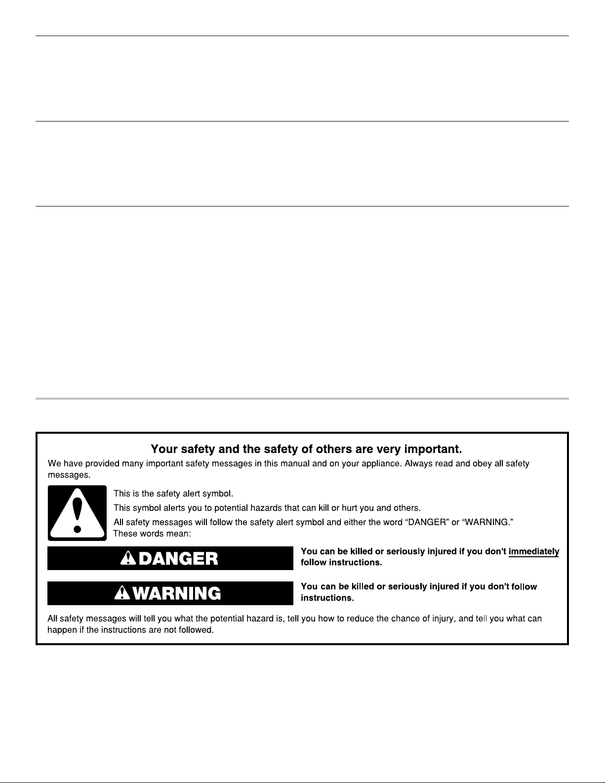
COOKTOP SAFETY
IMPORTANT:
Installer: Leave installation instructions with the homeowner.
Homeowner: Keep installation instructions for future reference.
IMPORTANT :
Installateur : Remettre les instructions d’installation au propriétaire.
Propriétaire : Conserver les instructions d’installation pour référence ultérieure.
W10848427D
Page 2
WARNING: If the information in these instructions is not followed exactly, a fire or
explosion may result causing property damage, personal injury or death.
– Do not store or use gasoline or other flammable vapors and liquids in the vicinity of this
or any other appliance.
– WHAT TO DO IF YOU SMELL GAS:
Do not try to light any appliance.
•
Do not touch any electrical switch.
•
Do not use any phone in your building.
•
Immediately call your gas supplier from a neighbor's phone. Follow the gas supplier's
•
instructions.
If you cannot reach your gas supplier, call the fire department.
•
Installation and service must be performed by a qualified installer, service agency or
–
the gas supplier.
WARNING: Gas leaks cannot always be detected by smell.
Gas suppliers recommend that you use a gas detector approved by UL or CSA.
For more information, contact your gas supplier.
If a gas leak is detected, follow the “What to do if you smell gas” instructions.
IMPORTANT: Do not install a ventilation system that blows air downward toward this gas cooking appliance. This type of
ventilation system may cause ignition and combustion problems with this gas cooking appliance resulting in personal injury or
unintended operation.
In the State of Massachusetts, the following installation instructions apply:
■ Installations and repairs must be performed by a qualified or licensed contractor, plumber, or gas fitter qualified or licensed by
the State of Massachusetts.
■ Acceptable Shut-off Devices: Gas Cocks and Ball Valves installed for use shall be listed.
■ A flexible gas connector, when used, must not exceed 4 feet (121.9 cm).
2
Page 3

INSTALLATION REQUIREMENTS
Tools and Parts
Gather the required tools and parts before starting installation.
Read and follow the instructions provided with any tools
listed here.
Tools needed
■ Tape measure
■ Flat-blade screwdriver
■ Phillips head screwdriver
■ Drill
■ Level
■ 6" (15.2 cm) socket
extension
■ Marker or pencil
■ Pliers
Parts supplied
■ Vent grill
■ Pre-filter
■ Propane conversion kit
■ Burner caps
■ Burner grates
■ Plenum
Parts needed
■ Metal ducting
■ Vent clamps
■ Wall cap
6" (15.2 cm) Round Surface Wall Cap Damper Order Part
Number A406
1
3
/4" x 10" (8.3 cm x 25.4 cm) Surface Wall Cap Damper
Order Part Number A403
To order, see the “Assistance or Service” section of the Use
and Care Guide.
Check local codes and consult gas supplier. Check existing gas
supply and electrical supply. See the “Electrical Requirements”
and “Gas Supply Requirements” sections.
It is recommended that all electrical connections be made by
a licensed, qualified electrical installer.
■ 1/4" (6.4 mm) drill bit
■ Jigsaw
■ Ratchet with 3/8" (9.5 mm)
socket
■ Pipe-joint compound
resistant to Propane gas
■ Noncorrosive leak-
detection solution
■ 1/4" (6.4 mm) nut driver
■ Plenum screw pack
■ Downdraft motor
assembly
■ Clamping brackets (2)
■ Bracket attachment
screws (2)
■ #10-16 x 3" (7.62 cm)
clamping screws
Location Requirements
IMPORTANT: Observe all governing codes and ordinances.
When installing cooktop, use minimum dimensions given.
■ It is the installer’s responsibility to comply with installation
clearances specified on the model/serial/rating plate. The
model/serial/rating plate is located on the bottom of the
cooktop.
■ The cooktop should be installed in a location away from
strong draft areas, such as windows, doors, and strong
heating vents or fans.
■ All openings in the wall or floor where cooktop is to be
installed must be sealed.
■ Cabinet opening dimensions that are shown must be used.
Given dimensions are minimum clearances.
■ Grounded electrical supply is required. See the “Electrical
Requirements” section. Proper gas supply connection must
be available. See the “Gas Supply Requirements” section.
■ The cooktop is designed to hang from the countertop by its
side or rear flanges.
■ The gas and electric supply should be located as shown in
the “Cabinet Dimensions” section so that they are accessible
without requiring removal of the cooktop.
■ Provide cutout in right rear corner of cabinet enclosure
as shown to provide clearance for gas inlet and power
supply cord.
■ If cabinet has drawers, drawers will need to be removed
and drawer fronts installed on front of cabinet.
IMPORTANT: An undercounter built-in oven cannot be installed
under this product.
IMPORTANT: To avoid damage to your cabinets, check with
your builder or cabinet supplier to make sure that the materials
used will not discolor, delaminate, or sustain other damage. This
cooktop has been designed in accordance with the requirements
of UL and CSA International and complies with the maximum
allowable wood cabinet temperatures of 194°F (90°C).
Mobile Home - Additional Installation Requirements
The installation of this cooktop must conform to the
Manufactured Home Construction and Safety Standard, Title 24
CFR, Part 3280 (formerly the Federal Standard for Mobile Home
Construction and Safety, Title 24, HUD Part 280). When such
standard is not applicable, use the Standard for Manufactured
Home Installations, ANSI A225.1/NFPA 501A or local codes.
In Canada, the installation of this cooktop must conform with
the current standards CAN/CSA-A240 — latest edition — or with
local codes.
3
Page 4
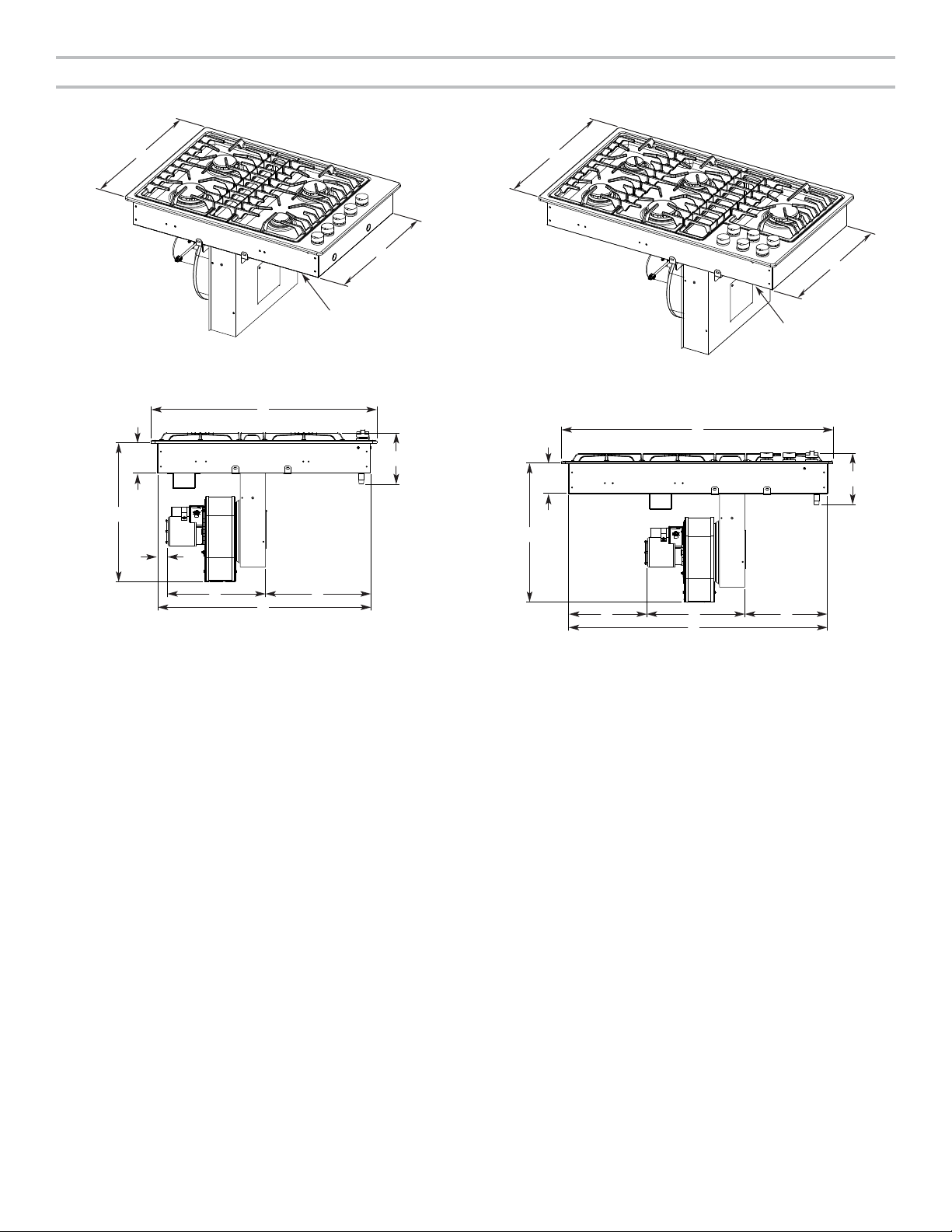
Product Dimensions
30" (76.2 cm) Cooktop 36" (91.4 cm) Cooktop
A
A. 211/2" (54.6 cm)
31
B. 19
/32" (50.7 cm)
C. Model/serial/rating plate location
B
D
E
A. 30" (76.2 cm)
9
B. 4
/64" (10.5 cm)
47
C. 6
/64" (17.1 cm)
5
D. 18
/16" (46.5 cm)
C
A
GF
H
11
E. 1
/16" (4.3 cm)
recommended
minimum cabinet
to motor clearance
29
F. 14
/64" (36.7 cm)
23
G. 12
/32" (32.3 cm)
25
H. 28
/64" (72.1 cm)
A
B
B
C
A. 211/2" (54.6 cm)
31
B. 19
/32" (50.7 cm)
C. Model/serial/rating plate location
A
C
C
B
D
E
GF
H
3
E. 10
A. 36" (91.4 cm)
9
B. 4
/64" (10.5 cm)
13
C. 7
/64" (18.3 cm)
5
D. 18
/16" (46.5 cm)
/8" (26.4 cm)
recommended
minimum cabinet
to motor clearance
29
F. 14
/64" (36.7 cm)
51
G. 9
/64" (24.9 cm)
17
H. 34
/32" (87.7 cm)
4
Page 5
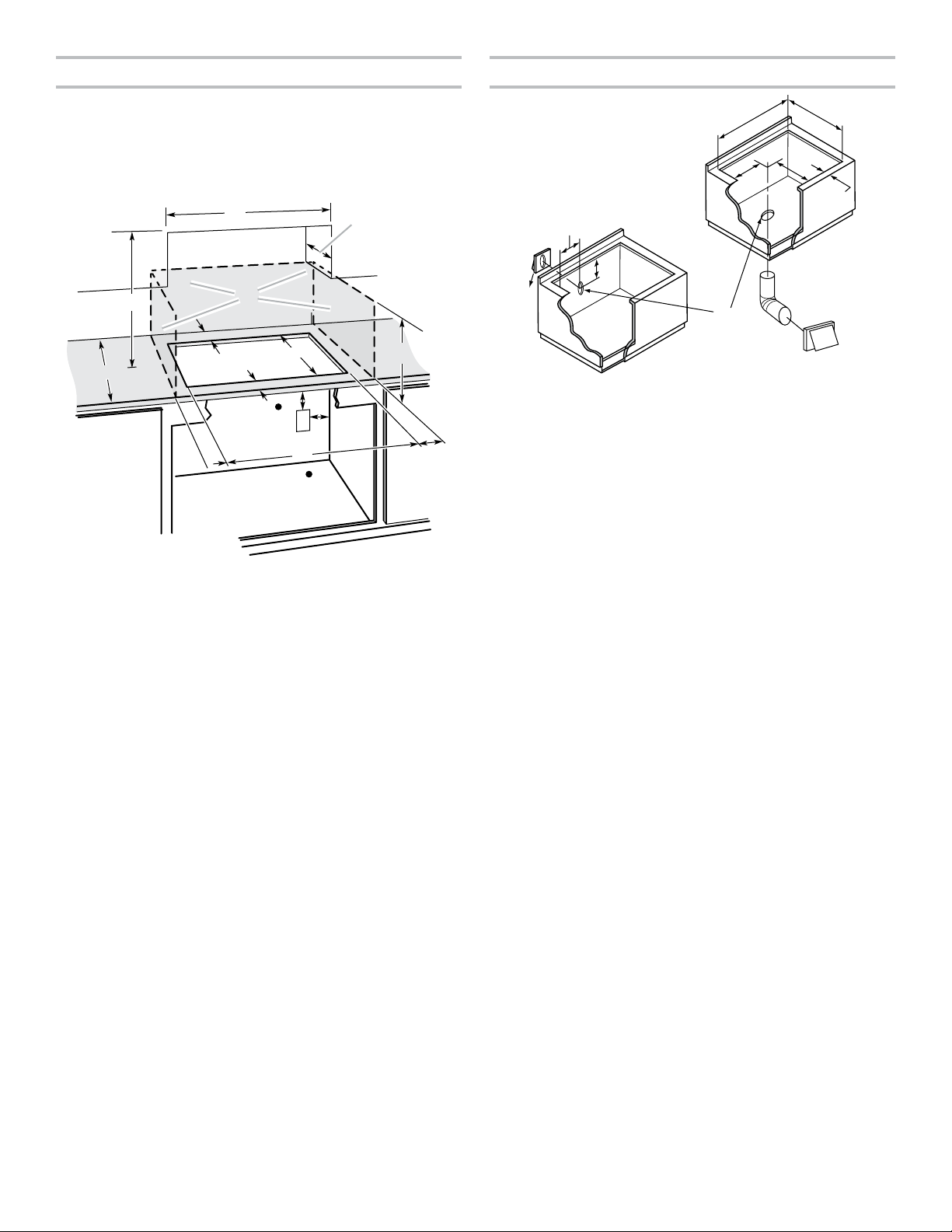
Cabinet Dimensions
Cutout Dimensions
IMPORTANT: If installing a range hood or microwave
hood combination above the range, follow the range
hood or microwave hood combination installation
instructions for dimensional clearances above the
cooktop surface.
A
C
N
B
L
E
F
M
K
J
M
A. 30" (76.2 cm) on 30" (76.2 cm) models
36" (91.4 cm) on 36" (91.4 cm) models
B. Combustible area above countertop (shown by dashed box above)
C. 30" (76.2 cm) minimum clearance between top of cooktop platform
and bottom of uncovered wood or metal cabinet (24" [61.0 cm]
minimum clearance if bottom of wood or metal cabinet is covered by
not less than 1/4" [6.4 mm] flame-retardant millboard covered with
not less than No. 28 MSG sheet steel, 0.015" [0.4 mm] stainless steel,
0.024" [0.6 mm] aluminum, or 0.020" [0.5 mm] copper)
D. 13" (33.0 cm) recommended upper cabinet depth
1
E. 2
/8" (5.4 cm)
15
F. 19
/16" (50.6 cm)
G. 18" (45.7 cm) minimum clearance from upper cabinet to countertop
within minimum horizontal clearances to cooktop
H. Junction box or outlet: 12" (30.5 cm) minimum from bottom of
countertop
I. Junction box or outlet: 10" (25.4 cm) from right-hand side of cabinet
5
J. 28
/8" (72.7 cm) on 30" (76.2 cm) models
343/4" (88.3 cm) on 36" (91.4 cm) models
K. 6" (15.2 cm) minimum distance to nearest left and right side
combustible surface above cooktop
L. 2" (5.1 cm) minimum clearance between back wall and countertop
cutout
M. Gas line opening - wall: anywhere 6" (15.2 cm) below underside of
countertop. Cabinet floor: anywhere within 6" (15.2 cm) of rear wall
is recommended.
N. 25" (63.5 cm) depth of countertop
NOTE: After making the countertop cutout, some installations
may require notching down the base cabinet side walls to clear
the cooktop base. To avoid this modification, use a base cabinet
with sidewalls wider than the cutout.
■ A minimum side clearance of 6" (15.2 cm) is recommended
between side of cooktop and side wall for maximum
ventilation performance.
D
G
H
I
K
A
D
C
F
H
I
J
G
A. 285/8" (72.7 cm) maximum on 30" (76.2 cm) models
343/4" (88.3 cm) maximum on 36" (91.4 cm) models
15
B. 19
/16" (50.6 cm) maximum on both 30" (76.2 cm) and
36" (91.4 cm) models
7
C. 7
/8" (20.0 cm) on 30" (76.2 cm) models
163/16" (41.1 cm) on 36" (91.4 cm) models
3
D. 5
/4" (14.6 cm) on both 30" (76.2 cm) and 36" (91.4 cm) models
1
E. 2
/8" (5.4 cm) minimum space to front edge of cooktop
F. Floor exhaust option
1
G. 6
/8" (15.6 cm) for 6" (15.2cm) vent system
7
H. 7
/8" (20.0 cm) on 30" (76.2 cm) models
163/16" (41.1 cm) on 36" (91.4 cm) models
11
I. 14
/16" (37.3 cm) on both 30" (76.2 cm) and 36" (91.4 cm)
models
J. Wall exhaust option
B
E
5
Page 6

Venting Requirements
IMPORTANT: This cooktop must be exhausted outdoors unless
using the Duct-Free Filter Accessory Kit. See the “Venting
Methods” section.
■ Do not terminate the vent system in an attic or other
enclosed area.
■ Use a vent cap.
■ Vent system must terminate to the outside.
■ Use only a 6" (15.2 cm) round metal vent. Rigid metal vent is
recommended. For best performance, do not use plastic or
metal foil vent.
■ Before making cutouts, make sure there is proper clearance
within the wall or floor for the exhaust vent.
■ Do not cut a joist or stud unless absolutely necessary. If a
joist or stud must be cut, then a supporting frame must be
constructed.
■ The size of the vent should be uniform.
■ The vent system must have a damper.
■ Use vent clamps to seal all joints in the vent system.
■ Use caulking to seal exterior wall or roof opening around
the cap.
■ Determine which venting method is best for your application.
For Best Performance:
■ Use 26-gauge minimum galvanized or 25-gauge minimum
aluminum metal vent. Poor quality pipe fittings can reduce
airflow. Flexible metal vent is not recommended.
NOTE: Local codes may require a heavier gauge material.
■ Metal duct may be reduced to 30-gauge galvanized steel
or 26-gauge aluminized steel if allowed by local codes.
This reduction is based on information in the International
Residential Codes Section M1601.1 (2006 edition).
■ Do not install two elbows together.
■ Use no more than three 90° elbows.
■ If an elbow is used, install it as far away as possible from
the vent motor exhaust opening.
■ Make sure there is a minimum of 18" (45.7 cm) of straight
vent between the elbows if more than 1 elbow is used.
■ Elbows too close together can cause excess turbulence that
reduces airflow.
■ Do not use a 5" (12.7 cm) elbow in a 6" (15.2 cm).
■ Do not reduce to a 5" (12.7 cm) system after using 6" (15.2 cm).
■ Avoid forming handmade crimps. Handmade crimps may
restrict airflow.
■ Use a vent cap for proper performance. If an alternate wall
or roof cap is used, be certain the cap size is not reduced
and that it has a backdraft damper.
■ Use vent clamps to seal all joints in the vent system.
■ Use caulking to seal exterior wall or roof opening around
the cap.
The length of vent system and number of elbows should be kept
to a minimum to provide efficient performance.
The maximum equivalent length of the vent system is 60 ft
(18.3 m). For altitudes above 4,500 ft (1,272 m), reduce
recommended vent run by 20% for best performance.
Cold Weather Installations
An additional backdraft damper should be installed to minimize
backward cold airflow.
Makeup Air
Local building codes may require the use of makeup air systems
when using ventilation systems greater than specified CFM of
air movement. The specified CFM varies from locale to locale.
Consult your HVAC professional for specific requirements in
your area.
6
Page 7

Venting Methods
Common venting methods are shown for a counter-mounted
downdraft cooktop. The cooktop may be vented through the
wall or floor.
Concrete Slab Installations - Exhaust Through Wall
B
Option 1 - Roof Venting Option 2 - Wall Venting
B
B
A
A
A. 6" (15.2 cm) round roof venting
B. Roof cap
Option 3 - Venting
Between Floor Joist
A
B
A. 6" (15.2 cm) round wall venting
B. Wall cap
Option 4 - Venting Behind
Cabinet Kick Plate
3¼" x 10"
(8.3 cm x 25.4 cm)
A B
A
N
M
L
A. Wall cap
B. 6" (15.2 cm) round metal vent
C. 16" (40.6 cm) maximum
D. 6" (15.2 cm) round PVC sewer pipe
E. 6" (15.2 cm) round metal duct
F. 6" (15.2 cm) round PVC coupling
G. Concrete slab
H. 6" (15.2 cm) round PVC sewer pipe
I. 6" (15.2 cm) round 90° PVC sewer pipe elbow
J. Tightly pack gravel or sand completely around pipe.
K. 30 ft (9.1 m) max.
L. 6" (15.2 cm) round 90° PVC sewer pipe elbow
M. 6" (15.2 cm) round PVC coupling
N. 12" (30.5 cm) minimum
C
K
D
E
F
G
H
I
J
Duct-Free Filter Accessory Kit
The Duct-Free Filter Accessory Kit, Part Number JDA7000WX,
is now available. Duct-Free Filter Accessory Kit is ideal for both
new construction and kitchen renovation projects because it
provides an easy alternative to the installation of metal ducting
and venting in the downdraft system outside the home. The
kit includes all required hardware, one filter, and complete
installation instructions. Replacement Filter Part Number
W10177003 is available.
A. Wall cap
B. 6" (15.2 cm) round wall venting
A. Wall cap
B. 6" (15.2 cm) round wall venting
7
Page 8

Calculating Vent System Length
(0.6 m)
wall cap
To calculate the length of the system you need, add the
equivalent feet (meters) for each vent piece used in the system.
Vent Piece 6" (15.2 cm) Round
45° elbow 2.5 ft
(0.8 m)
90° elbow 5.0 ft
(1.5 m)
6" (15.2 cm) wall cap 0.0 ft
(0.0 m)
31/4" x 10" (8.3 cm x 25.4 cm)
to 6" (15.2 cm) transition
6" (15.2 cm) to 31/4" x 10"
(8.3 cm x 25.4 cm) transition
31/4" x 10" (8.3 cm x 25.4 cm)
to 6" (15.2 cm) 90° elbow
transition
6" (15.2 cm) to 31/4" x 10"
(8.3 cm x 25.4 cm) 90° elbow
transition
31/4" x 10" (8.3 cm x 25.4 cm)
90° elbow
31/4" x 10" (8.3 cm x 25.4 cm)
flat elbow
31/4" x 10" (8.3 cm x 25.4 cm)
wall cap
4.5 ft
(1.4 m)
1 ft
(0.3 m)
5.0 ft
(1.5 m)
5.0 ft
(1.5 m)
5.0 ft
(1.5 m)
12.0 ft
(3.7 m)
0.0 ft
(0.0 m)
Example vent system
90˚ elbow
6 ft (1.8 m)
2 ft
1- 90° elbow = 5 ft (1.5 m)
8 ft (2.4 m) straight = 8 ft (2.4 m)
1 - wall cap = 0 ft (0 m)
System length = 13 ft (3.9 m)
NOTE: Flexible vent is not recommended. Flexible vent
creates back pressure and air turbulence that greatly reduce
performance.
Electrical Requirements
IMPORTANT: The cooktop must be electrically grounded in
accordance with local codes and ordinances, or in the absence
of local codes, with the National Electrical Code, ANSI/NFPA 70
or Canadian Electrical Code, CSA C22.1.
This cooktop is equipped with an electronic ignition system
that will not operate if plugged into an outlet that is not properly
polarized.
If codes permit and a separate ground wire is used, it is
recommended that a qualified electrical installer determine
that the ground path is adequate.
A copy of the above code standards can be obtained from:
National Fire Protection Association
1 Batterymarch Park
Quincy, MA 02169-7471
CSA International
8501 East Pleasant Valley Road
Cleveland, Ohio 44131-5575
■ A 120-volt, 60 Hz, AC-only, 15-amp, fused electrical circuit
is required. A time-delay fuse or circuit breaker is also
recommended. It is recommended that a separate circuit
serving only this cooktop be provided.
■ Electronic ignition systems operate within wide voltage limits,
but proper grounding and polarity are necessary. Check that
the outlet provides 120-volt power and is correctly grounded.
■ The wiring diagrams are provided with this cooktop. See
“Wiring Diagrams” on a separate sheet. The wiring diagrams
are located on the underside of the cooktop base.
■ This gas cooktop is not required to be plugged into a GFCI-
(Ground-Fault Circuit Interrupter) outlet or AFCI- (Arc Fault
Circuit Interrupter) type circuit breaker. It is recommended
that you not plug an electric spark ignition gas cooktop or
any other major appliance into a GFCI wall outlet or an AFCItype circuit breaker as it may cause these types of circuit
breakers to trip during normal cycling.
■ Performance of this cooktop will not be affected if operated
on a GFCI/AFCI-protected circuit. However, occasional
nuisance tripping of the GFCI breaker is possible due to the
normal operating nature of electronic gas cooktops.
8
Page 9

Gas Supply Requirements
WARNING
Explosion Hazard
Use a new CSA International approved gas supply line.
Install a shut-off valve.
Securely tighten all gas connections.
If connected to propane, have a qualified person make
sure gas pressure does not exceed 14" (36 cm) water
column.
Examples of a qualified person include:
licensed heating personnel,
authorized gas company personnel, and
authorized service personnel.
Failure to do so can result in death, explosion, or fire.
■ A 1/2" (13 mm) male pipe thread is needed for
connection to the female pipe threads of the inlet to the
cooktop pressure regulator.
■ Do not kink or damage the flexible metal tubing when
moving the cooktop.
■ Must include a shut-off valve:
Install a manual gas line shut-off valve in an easily accessible
location. Do not block access to shut-off valve. The valve is
for turning on or shutting off gas to the cooktop.
B
A
C
A. Gas supply line
B. Shut-off valve open position
C. To cooktop
Observe all governing codes and ordinances.
IMPORTANT: This installation must conform with all local codes
and ordinances. In the absence of local codes, installation must
conform with American National Standard, National Fuel Gas
Code ANSI Z223.1 — latest edition or CAN/CGA B149 — latest
edition.
IMPORTANT: Leak testing of the cooktop must be conducted
according to the manufacturer’s instructions.
Type of Gas
Natural Gas:
This cooktop is factory set for use with Natural gas. If converting
to Propane gas, see the “Propane Gas Conversion” instructions
provided in the package containing literature. The model/serial/
rating plate located on bottom of the cooktop has information
on the types of gas that can be used. If the types of gas listed
do not include the type of gas available, check with the local gas
supplier.
Propane Gas Conversion:
Conversion must be done by a qualified service technician.
No attempt shall be made to convert the cooktop from the gas
specified on the model/serial/rating plate for use with a different
gas without consulting the serving gas supplier. See the “Gas
Conversion” instructions provided in the package containing
literature.
Gas Supply Line
■ Provide a gas supply line of 3/4" (19 mm) rigid pipe to the
cooktop location. A smaller size pipe on longer runs may
result in insufficient gas supply. Pipe-joint compounds that
resist the action of Propane gas must be used. Do not
use TEFLON
size should be 1/2" (13 mm) minimum. Usually, Propane
gas suppliers determine the size and materials used in the
system.
Flexible metal appliance connector:
■ If local codes permit, use a 1/2" (13 mm) or 3/4" (19
mm) I.D. flexible stainless steel tubing gas connector,
designed by CSA to connect the cooktop to the rigid gas
supply line.
®†
tape. With Propane gas, piping or tubing
Gas Pressure Regulator
The gas pressure regulator supplied with this cooktop must be
used. The inlet pressure to the regulator should be as follows
for proper operation:
Natural Gas:
Minimum pressure: 5" (12.7 cm) WCP
Maximum pressure: 7" to 14" (17.8 cm to 35.5 cm) WCP
Propane Gas:
Minimum pressure: 10" (25.4 cm) WCP
Maximum pressure: 14" (35.5 cm) WCP
Contact local gas supplier if you are not sure about the inlet
pressure.
Burner Input Requirements
Input ratings shown on the model/serial/rating plate are for
elevations up to 2,000 ft (609.6 m).
For elevations above 2,000 ft (609.6 m), ratings should be
reduced at a rate of 4% for each 1,000 ft (304.8 m) above
sea level (not applicable for Canada).
Gas Supply Pressure Testing
Gas supply pressure for testing regulator must be at least 2.5 cm
water column pressure above the manifold pressure shown on
the model/serial/rating plate.
Line pressure testing above 1/2 psi (3.5 kPa) gauge (35.6 cm
WCP)
The cooktop and its individual shut-off valve must be
disconnected from the gas supply piping system during any
pressure testing of that system at test pressures in excess
of 1/2 psi (3.5 kPa).
Line pressure testing at 1/2 psi (3.5 kPa) gauge (35.6 cm
WCP) or lower
The cooktop must be isolated from the gas supply piping
system by closing its individual manual shut-off valve during
any pressure testing of the gas supply piping system at test
pressures equal to or less than 1/2 psi (3.5 kPa).
†®TEFLON is a registered trademark of Chemours.
9
Page 10

INSTALLATION INSTRUCTIONS
Prepare Cooktop
Decide on the final location for the cooktop.
WARNING
Excessive Weight Hazard
Use two or more people to move and install cooktop.
Failure to do so can result in back or other injury.
IMPORTANT: Do not cut top of product packaging. This may
damage the product.
1. Open product as instructed on product packaging.
2. Remove all items from both sides of the foam and set aside.
Take out packaging foam and set aside to lay cooktop on.
IMPORTANT: Do not place packaging foam on knobs.
3. Using two or more people, remove cooktop and place the
cooktop upside down on the packaging foam, making sure
the knobs are not laid on the foam.
7. Using a 1/4" (6.4 mm) nut driver, screw in the six screws from
the literature pack to attach plenum.
8. Remove access panel from plenum using a 1/4" (6.4 mm) nut
driver and set aside.
B
A
A. Access panel
B. Two screws
9. Remove four locking nuts and four washers from literature bag.
NOTE: Remove the four protective caps from the motor
mounting posts.
10. Place blower motor on plenum.
4. Remove plenum and plenum screw pack (in the package
containing literature).
5. Remove downdraft motor assembly.
6. Place plenum on bottom of cooktop with round opening
to the motor wire harness.
NOTE: All holes are pre-drilled. If all six holes do not line up,
reverse plenum.
A
B
C
A
B
A. Blower motor
B. Plenum
11. Install and finger-tighten the four washers and locking nuts
that were removed through the opening of the motor access
panel. Do not over-tighten to allow for motor to rotate.
12. Connect blower electrical connector to cooktop.
10
A. Plenum
B. Cooktop
C. Motor wire harness
Page 11

13. Using a 1/4" (6.4 mm) nut driver, screw the electrical junction
WARNING
cover to the burner box with two screws.
14. Remove the two screws located in each side of the cooktop
burner box.
Install Cooktop
Install the pressure regulator to cooktop before installing the
cooktop into the cabinet. See the “Make Gas Connection”
section.
3. Using two or more people, lift the cooktop from packaging
foam and install the cooktop into the countertop cutout by
tilting one end of the cooktop into the cutout, then lowering
the other end into the cutout.
NOTE: Make sure that the front edge of the cooktop is
parallel to the front edge of the countertop. If repositioning
is needed, lift entire cooktop up from cutout to avoid
scratching the countertop.
4. Rotate motor to align with duct work and attach ducting.
5. Fully tighten motor and, using a 1/4" (6.4 mm) nut driver,
reattach motor access cover with two screws.
IMPORTANT: Verify that the motor access cover is fully
tightened and back on the plenum.
6. Select bracket mounting holes that will allow the bracket to
extend far enough out from the cooktop for the installation of
#10-16 x 3" (7.62 cm) clamping screws.
G
A
B
F
E
Excessive Weight Hazard
Use two or more people to move and install cooktop.
Failure to do so can result in back or other injury.
1. Install the pressure regulator with the arrow pointing up
toward the bottom of the cooktop base and in a position
where you can reach the regulator access cap.
B
A
C
D
A. Access cap
B. Rear of cooktop
C. Gas pressure regulator
D. Up arrow. Regulator must be installed with
arrow pointing up to cooktop bottom
IMPORTANT: All connections must be wrench-tightened. Do
not make connections to the gas regulator too tight. Making
the connections too tight may crack the regulator and cause
a gas leak. Do not allow the regulator to turn on the pipe
when tightening fittings.
Use only pipe-joint compound made for use with Natural and
Propane gas.
®
Do not use TEFLON
tape. You will need to determine the
fittings required depending on your installation.
2. Attach the two hold-down brackets to the burner box.
D
C
A. Cooktop
B. Cooktop base
C. Attachment screw
D. Clamping bracket (extends far
enough beyond cooktop base to
allow installation of clamping screws)
E. #10-16 x 3" (7.62 cm) clamping
screw (to be installed in “Attach
Cooktop to Countertop”)
F. Countertop
G. Foam seal
7. Attach brackets to cooktop base bottom with bracket
attachment screws using the bracket mounting holes
selected in Step 6. Securely tighten screws.
8. Install grease filter.
A
B
A. Plenum
B. Grease filter
NOTES:
■ The filter should always be placed at an angle. As you
face the front of the cooktop, the top of the filter should
rest against the right side of the vent opening.
■ The bottom of the filter should rest against the left side
of the vent chamber at the bottom.
■ If the filter is flat against the fan wall, ventilation
effectiveness will be reduced.
9. Install vent grille.
11
Page 12

WARNING
Make Gas Connection
Complete Connection
1. Open the manual shut-off valve in the gas supply line. The
valve is open when the handle is parallel to the gas pipe.
A
B
Explosion Hazard
Use a new CSA International approved gas supply line.
Install a shut-off valve.
Securely tighten all gas connections.
If connected to propane, have a qualified person make
sure gas pressure does not exceed 14" (36 cm) water
column.
Examples of a qualified person include:
licensed heating personnel,
authorized gas company personnel, and
authorized service personnel.
Failure to do so can result in death, explosion, or fire.
1. Apply pipe-joint compound made for use with Natural
and Propane gas to the smaller thread ends of the flexible
connector adapters (see C and G in the following illustration).
2. Attach one adapter to the gas pressure regulator and
the other adapter to the gas shut-off valve. Tighten both
adapters, being certain not to move or turn the gas pressure
regulator.
3. Use a 15/16" (24 mm) combination wrench and channel lock
pliers to attach the flexible connector to the adapters. Check
that connector is not kinked.
Typical flexible connection
A. Closed valve
B. Open valve
2. Test all connections by brushing on an approved
noncorrosive leak-detection solution. If bubbles appear,
a leak is indicated. Correct any leak found.
3. Remove surface burner caps and grates from packaging.
Place burner caps on burner bases. Burner caps should
be level when properly positioned. If burner caps are not
properly positioned, surface burners will not light. Place
burner grates over burners and caps.
IMPORTANT:
during conversion. Be sure that the electrode comes through the
hole in the burner base smoothly.
The igniter electrode is ceramic and could break
A
A. Burner cap
B. Electrode
C. Burner base
B
C
12
A
B
C
D
E
F
G
H
I
A. Manifold entrance
B. Gas pressure regulator
C. Use pipe-joint compound.
D. Adapter (must have 1/2" (13 mm) male
pipe thread)
E. Flexible connector
F. Adapter
G. Use pipe-joint compound.
H. Manual gas shut-off valve
I. 1/2" (13 mm) or 3/4" (19 mm) gas pipe
Page 13

4. Plug into a grounded 3 prong outlet.
A
B
NOTE: If the cooktop does not work after turning on the power,
check that a circuit breaker has not tripped or a household fuse
has not blown. See the “Troubleshooting” section in the Use and
Care Guide for further information.
Attach Cooktop to Countertop
NOTE: This section applies only if you are using clamping
brackets.
G
A
Electronic Ignition System
Initial Lighting and Gas Flame Adjustments
This cooktop is equipped for electronic auto-reignition by means
of a spark igniter located at the rear of each burner. The burners
are designed to light at any valve rotation that admits sufficient
gas flow to support a flame and to automatically relight following
a loss of flame due to a draft or other adverse condition. This
feature is provided only as a convenience.
Check Operation of Surface Burners
Push in and turn the surface burners control knobs to light.
The surface burner flame should light within 4 seconds. The first
time a surface burner is lit, it may take longer than 4 seconds to
light because of air in the gas line.
Check the flame on High for a blue color. It should be clean and
soft in character. No yellow tip, blowing or lifting of flame should
occur. Occasional orange flashes are normal and reflect different
elements in the air or gas.
After verifying the proper burner operation, turn the control
knobs to OFF.
If burners do not light properly:
■ Turn surface burner control knob to OFF.
■ Check that the power supply cord is plugged in and the
circuit breaker has not tripped or the fuse blown.
■ Check that the gas shut-off valves are set to the open
position.
■ Check that burner caps are properly positioned on
burner bases.
Recheck operation of surface burners. If a burner does not light
at this point, contact your dealer or authorized service company
for assistance.
B
F
E
D
C
A. Cooktop
B. Cooktop base
C. Attachment screw
D. Clamping bracket (extends far
enough beyond cooktop base to
allow installation of clamping screws)
E. #10-16 x 3" (7.62 cm) clamping
screw
F. Countertop
G. Foam seal
1. Place the #10-16 x 3" (7.62 cm) clamping screws into the
outermost hole in the clamping bracket.
2. Check that the cooktop is still level.
3. Use a screwdriver to tighten the screws against the
countertop. Do not overtighten.
Adjust Flame Height
Smart Port Burner System
This cooktop is equipped with a Smart Port Burner System. The
Smart Port Burner System produces a small flame directly under
each grate finger and a larger flame between each grate finger.
The visual difference between the ports will be noticeable when
the burner is used or when adjustments are made to the flame
length.
Adjust the height of top burner flames. The cooktop Low
burner flame should be a steady blue flame approximately
1/4" (6.4 mm) high.
A. Low flame
B. High flame
To adjust standard burners:
The flame can be adjusted using the adjustment screw in
the center of the valve stem. The valve stem is located
directly underneath the control knob.
13
Page 14

If the low flame needs to be adjusted:
1. Light one burner and turn to lowest setting.
2. Remove the control knob.
3. Hold the knob stem in the low position using a pair of pliers.
Use an 1/8" (3.0 mm) flat-blade screwdriver to turn the screw
located in the center of the control knob stem until the flame
is the proper size.
4. Replace the control knob.
5. Test the flame by turning the control from Low to High,
checking the flame at each setting.
6. Repeat above steps for each burner.
Complete Installation
1. Check that all parts are now installed. If there is an extra
part, go back through the steps to see which step was
skipped.
2. Check that you have all your tools.
3. Dispose of/recycle all packaging materials.
4. Use a mild solution of liquid household cleaner and warm
water to clean cooktop before use. Dry thoroughly with a
soft cloth. For more information, see the “Cooktop Care”
section of the Use and Care Guide.
5. Read the “Cooktop Use” section in the cooktop Use and
Care Guide.
6. Reconnect power.
If you need Assistance or Service:
Please reference the “Warranty” section of the Use and Care
Guide.
14
Page 15

W10848427D 08/17
©2017 Used under license in Canada. All rights reserved.
©2017 Utilisé sous licence au Canada. Tous droits réservés.
 Loading...