

Page 1
OUTDOOR BUILT-IN DUAL SIDE BURNERS
Installation Instructions and Use & Care Guide
For questions about features, operation/performance, parts, accessories or service, call: 1-800-422-1230
or visit our website at www.kitchenaid.com
In Canada, call for assistance, installation and service, call: 1-800-807-6777
or visit our website at www.KitchenAid.ca
DEUX BRÛLEURS LATÉRAUX ENCASTRÉS
POUR USAGE EXTÉRIEUR
Instructions d’installation et Guide d’utilisation et d’entretien
Au Canada, pour assistance, installation ou service composez le 1-800-807-6777 ou visitez notre site web à...
www.KitchenAid.ca
Table of Contents/Table des matières.............................................................................4
IMPORTANT:
Save for local electrical inspector's use.
Installer: Leave installation instructions with the homeowner.
Homeowner: Keep installation instructions for future reference.
IMPORTANT :
À conserver pour consultation par l'inspecteur local des installations électriques.
Installateur : Remettre les instructions d'installation au propriétaire.
Propriétaire : Conserver les instructions d'installation pour référence ultérieure.
Models/Modèles KBZU122VSS KBZU242VSS KBZU122TSS KBZU242TSS
W10176789A
Page 2
OUTDOOR BUILT-IN SIDE BURNER SAFETY
Your safety and the safety of others are very important.
We have provided many important safety messages in this manual and on your appliance. Always read and obey all safety
messages.
This is the safety alert symbol.
This symbol alerts you to potential hazards that can kill or hurt you and others.
All safety messages will follow the safety alert symbol and either the word “DANGER” or “WARNING.”
These words mean:
You can be killed or seriously injured if you don't immediately
DANGER
WARNING
All safety messages will tell you what the potential hazard is, tell you how to reduce the chance of injury, and tell you what can
happen if the instructions are not followed.
follow instructions.
can be killed or seriously injured if you don't
You
instructions.
follow
DANGER
If you smell gas:
1. Shut off gas to the appliance.
WARNING
1. Do not store or use gasoline or other
flammable liquids or vapors in the
vicinity of this or any other appliance.
2. Extinguish any open flame.
2. An LP cylinder not connected for use
3. Open lid.
4. If odor continues, keep away from the
shall not be stored in the vicinity of
this or any other appliance.
appliance and immediately call your
gas supplier or your fire department.
State of California Proposition 65 Warnings:
WARNING: This product contains a chemical known to the State of California to cause cancer.
WARNING: This product contains a chemical known to the State of California to cause birth defects or other reproductive harm.
In the State of Massachusetts, the following installation instructions apply:
■ Installations and repairs must be performed by a qualified or licensed contractor, plumber, or gasfitter qualified or licensed by
the State of Massachusetts.
■ If using a ball valve, it shall be a T-handle type.
■ A flexible gas connector, when used, must not exceed 3 feet.
2
Page 3

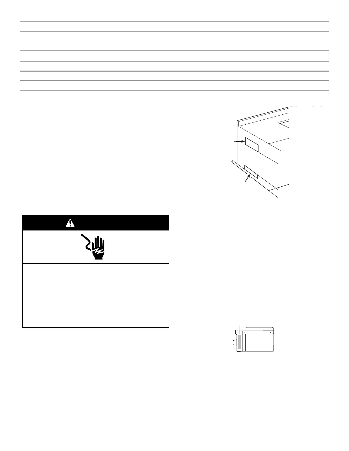
IMPORTANT: This side burner is manufactured for outdoor use only. For side burners that are to be used at elevations above
2000 ft (609.6 m) orifice conversion is required. See “Gas Supply Requirements” section. It is the responsibility of the installer to comply
with the minimum installation clearances specified on the model/serial rating plate. The model/serial rating plate can be found on the
right-hand side panel.
Copies of the standards listed may be obtained from:
National Fire Protection Association
One Batterymarch Park
Quincy, Massachusetts 02269
CSA International
8501 East Pleasant Valley Rd.
Cleveland, Ohio 44131-5575
IMPORTANT SAFETY INSTRUCTIONS
■
WARNING:
To reduce the risk of fire, electrical shock,
injury to persons, or damage when using the outdoor cooking
gas appliance, follow basic precautions, including the
following:
■
Do not install portable or built-in outdoor cooking gas
appliances in or on a recreational vehicle, portable trailer,
boat or in any other moving installation.
■
Always maintain minimum clearances from combustible
construction, see “Location Requirements” section.
■
The outdoor cooking gas appliance shall not be located
under overhead unprotected combustible construction.
■
This outdoor cooking gas appliance shall be used only
outdoors and shall not be used in a building, garage, or any
other enclosed area.
■
Keep any electrical supply cord and fuel supply hose away
from any heated surfaces.
■
Keep outdoor cooking gas appliance area clear and free
from combustible materials, gasoline and other flammable
vapors and liquids.
■
Do not obstruct the flow of combustion and ventilation air.
Keep the ventilation openings of the cylinder enclosure free
and clear from debris.
■
Inspect the gas cylinder supply hose before each use of the
outdoor cooking gas appliance. If the hose shows
excessive abrasion or wear, or is cut, it MUST be replaced
before using the outdoor cooking gas appliance. Contact
your dealer and use only replacement hoses specified for
use with the outdoor cooking gas appliance.
■
Visually check the burner flames. They should be blue.
Slight yellow tipping is normal for LP gas.
■
Check and clean burner/venturi tube for insects and insect
nest. A clogged tube can lead to fire under the outdoor
cooking gas appliance.
The LP gas supply cylinder to be used must be:
- constructed and marked in accordance with the
Specification for LP Gas Cylinders of the U.S. Department
of Transportation (DOT) or the National Standard of
Canada, CAN/CSA-B339, Cylinders, Spheres, and Tubes
for Transportation of Dangerous Goods; and Commission.
- provided with a listed overfilling prevention device.
- provided with a cylinder connection device compatible
with the connection for outdoor cooking gas appliances.
■
Always check connections for leaks each time you connect
and disconnect the LP gas supply cylinder. See
“Installation Instructions” section.
■
When the outdoor cooking gas appliance is not in use, the
gas must be turned off at the supply cylinder.
■
Storage of an outdoor cooking gas appliance indoors is
permissible only if the cylinder is disconnected and
removed from the outdoor cooking gas appliance.
■
Cylinders must be stored outdoors and out of the reach of
children and must not be stored in a building, garage, or
any other enclosed area.
■
The pressure regulator and hose assembly supplied with
the outdoor cooking gas appliance must be used. A
replacement pressure regulator and hose assembly
specific to your model is available from your outdoor
cooking gas appliance dealer.
■
Gas cylinder must include a collar to protect the cylinder
valve.
■
For appliances designed to use a CGA791 Connection:
Place a dust cap on cylinder valve outlet whenever the
cylinder is not in use. Only install the type of dust cap on
the cylinder valve outlet that is provided with the cylinder
valve. Other types of caps or plugs may result in leakage
of propane.
If the following information is not followed exactly, a fire
causing death or serious injury may occur.
■
Do not store a spare LP gas cylinder under or near this
outdoor cooking gas appliance.
■
Never fill the cylinder beyond 80 percent full.
SAVE THESE INSTRUCTIONS
3
Page 4

TABLE OF CONTENTS
TABLE DES MATIÈRES
OUTDOOR BUILT-IN SIDE BURNER SAFETY ............................2
INSTALLATION REQUIREMENTS................................................5
Tools and Parts ............................................................................5
Location Requirements................................................................ 6
Product Dimensions.....................................................................6
Cabinet Dimensions.....................................................................6
Electrical Requirements ...............................................................9
Gas Supply Requirements.........................................................10
Gas Connection Requirements - For Models Equipped for
LP Gas........................................................................................10
Gas Connection Requirements - For Models Equipped for
Natural Gas.................................................................................12
INSTALLATION INSTRUCTIONS................................................13
Built-in Outdoor Side Burner Installation...................................13
Install Tank Tray for 20 lb LP Gas Fuel Tank - For Models
Equipped for Use with a 20 lb LP Tank.....................................13
GAS CONVERSIONS....................................................................17
Tools and Parts for Gas Conversion..........................................17
Conversion to a Local LP Gas Supply.......................................17
Conversion from LP Gas to Natural Gas ...................................18
Check and Adjust the Burners...................................................19
USING YOUR OUTDOOR SIDE BURNER..................................20
Lighting Your Side Burner..........................................................20
OUTDOOR SIDE BURNER CARE...............................................21
General Cleaning........................................................................21
TROUBLESHOOTING ..................................................................22
ASSISTANCE OR SERVICE.........................................................22
In the U.S.A. ...............................................................................23
Accessories................................................................................23
In Canada ...................................................................................23
WARRANTY ..................................................................................23
SÉCURITÉ DU BRÛLEUR LATÉRAL
ENCASTRÉ D'EXTÉRIEUR..........................................................25
EXIGENCES D'INSTALLATION...................................................27
Outillage et pièces......................................................................27
Exigences d'emplacement.........................................................28
Dimensions du produit...............................................................28
Dimensions du placard ..............................................................28
Spécifications électriques ..........................................................31
Spécifications de l'alimentation en gaz .....................................32
Exigences concernant le raccordement au gaz - Pour les
modèles équipés pour le propane ............................................33
Exigences concernant le raccordement au gaz - Pour les
modèles équipés pour le gaz naturel.........................................34
INSTRUCTIONS D’INSTALLATION.............................................35
Installation du brûleur latéral d'extérieur encastré.....................35
Installation du chariot de bouteille de gaz propane de 20 lb Pour les modèles équipés pour l'utilisation d'une bouteille
de gaz propane de 20 lb ............................................................35
CONVERSIONS DE GAZ..............................................................39
Outillage et pièces......................................................................39
Conversion au gaz propane local ..............................................40
Conversion de gaz propane à Gaz naturel ................................41
Contrôle et réglage des brûleurs................................................42
UTILISATION DU BRÛLEUR LATÉRAL D'EXTÉRIEUR............43
Allumage du brûleur latéral ........................................................43
ENTRETIEN DU BRÛLEUR LATÉRAL D'EXTÉRIEUR ..............44
Nettoyage général ......................................................................44
DÉPANNAGE.................................................................................45
ASSISTANCE OU SERVICE.........................................................46
Accessoires ................................................................................46
Au Canada..................................................................................46
GARANTIE.....................................................................................47
4
Page 5

INSTALLATION REQUIREMENTS
Tools and Parts
Gather the required tools and parts before starting installation. Read and follow the instructions provided with any tools listed here.
20 lb LP Gas Models
Tools Needed
■ Tape m e asure
■ Small, flat-blade screwdriver
■ Flat-blade screwdriver
■ #2 and #3 Phillips screwdriver
■ Level
■ Wrench or pliers
■ Pipe wrench
■ Scissors or cutting pliers
(to remove tiedowns)
■ Noncorrosive leak-
detection solution
Parts Supplied
■ Gas pressure regulator/hose assembly set for 11" WCP LP
gas (attached to manifold)
■ 1 single-prong plug/5,000 mAmp transformer assembly
■ Convertible regulator set for 4" WCP Natural gas
■ Orifices for Natural gas conversion
■ LP gas fuel tank tray
Parts Needed
■ 20 lb LP gas fuel tank - approximately 18" (45.7 cm) height
and 12" (30.5 cm) diameter
Natural Gas Models
Tools Needed
■ Tape measure
■ Small, flat-blade screwdriver
■ Flat-blade screwdriver
■ #2 and #3 Phillips screwdriver
■ Level
■ Wrench or pliers
■ Pipe wrench
■ Scissors or cutting pliers
(to remove tiedowns)
■ Noncorrosive leak-
detection solution
Parts Needed
■ Gas line shutoff valve
■ ½" male pipe thread nipple for connection to pressure
regulator
■ LP gas-resistant pipe-joint compound
■ CSA design-certified outdoor flexible stainless steel
appliance connector (4-5 ft [1.2-1.5 m]) or rigid gas supply
line as needed.
Parts Supplied
■ Convertible regulator set for 4" WCP Natural gas.
■ Single-prong plug/5,000 mAmp transformer assembly
5
Page 6
Location Requirements
Select a location that provides minimum exposure to wind and
traffic paths. The location should be away from strong draft
areas.
Do not obstruct flow of combustion and ventilation air.
Clearance to combustible construction for built-in outdoor side
burners:
■ A minimum of 24" (58 cm) must be maintained between the
sides and back and any combustible construction.
■ A zero clearance may be maintained below the cooking
surface and any combustible construction.
Style 2 - Side by Side Built-In Dual Side Burners
A
B
B
C
Ignition
A grounded, 3-prong outdoor GFI outlet is to be located inside
the island cabinet and to the left of the side burner. See
“Electrical Requirements” section.
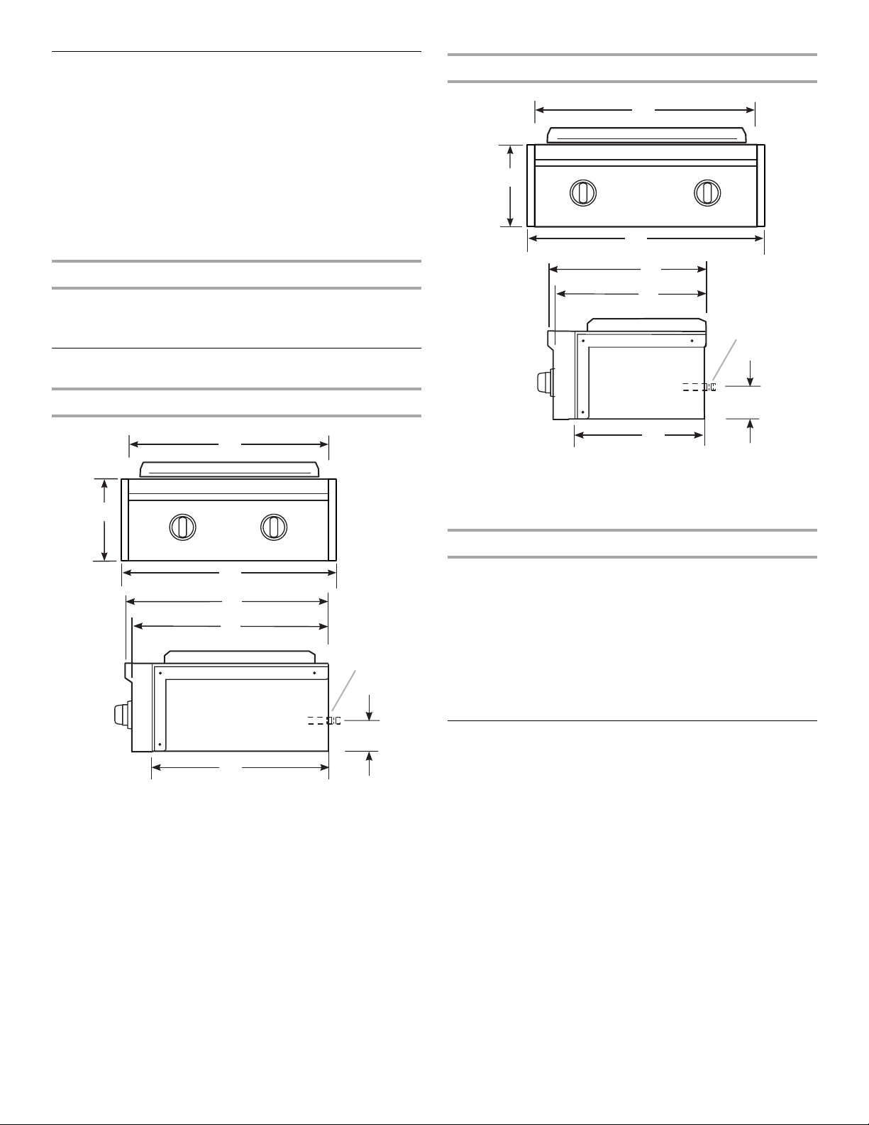
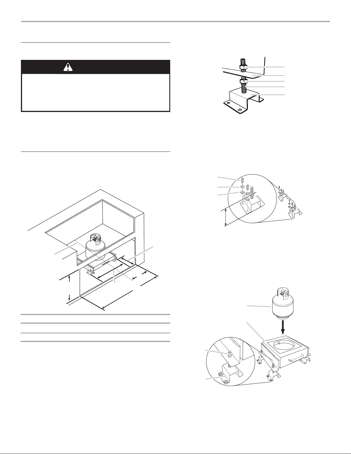
Product Dimensions
Style 1 - Front to Back Built-In Dual Side Burners
A
B
B
C
D
E
F
D
E
F
G
H
A. 24" (61 cm)
B. 10⁵⁄₈" (27 cm)
C. 28" (71.1 cm)
D. 20¹⁄₂" (52.1 cm)
E. 19¹⁄₂" (49.5 cm)
F. M a n if o l d p ip e
G. 4³⁄₈" (11.1 cm)
H. 17" (43.2 cm)
Built-In Outdoor Side Burner Enclosure
This built-in outdoor side burner is for installation in a built-in
enclosure constructed of combustible and non-combustible
materials. Some types of non-combustible materials could be
brick, firewall or steel. Some types of combustible materials
could be wood or laminate.
The enclosure for the built-in outdoor side burner is to be a
minimum of 11" (28.0 cm) high x 23" (58.4 cm) deep x
14" (35.6 cm) wide for front to back model and 11" (28.0 cm)
high x 17" (43.2 cm) deep x 25" (63.5 cm) wide for side by side
model.
G
H
Counter or support surfaces must be level.
Cabinet Dimensions
The installation of this side burner must conform with local codes
A. 13" (33 cm)
B. 10⁵⁄₈" (27 cm)
C. 17" (43.2 cm)
D. 26³⁄₈" (67 cm)
E. 25³⁄₈" (64.5 cm)
F. Manifold pipe
G. 4³⁄₈" (11.1 cm)
H. 22³⁄₄" (57.8 cm)
or, in the absence of local codes, with either the National Fuel
Gas Code, ANSI Z223.1/NPFA 54, Natural Gas and Propane
Installation Code, CSA B149.1, or Propane Storage and Handling
Code, B149.2.
Copies of the standards listed may be obtained from:
CSA International
8501 East Pleasant Valley Rd.
Cleveland, Ohio 44131-5575
NOTE: The outdoor side burner drops into the enclosure opening
and is supported by its side flanges. No bottom support is
needed.
6
Page 7
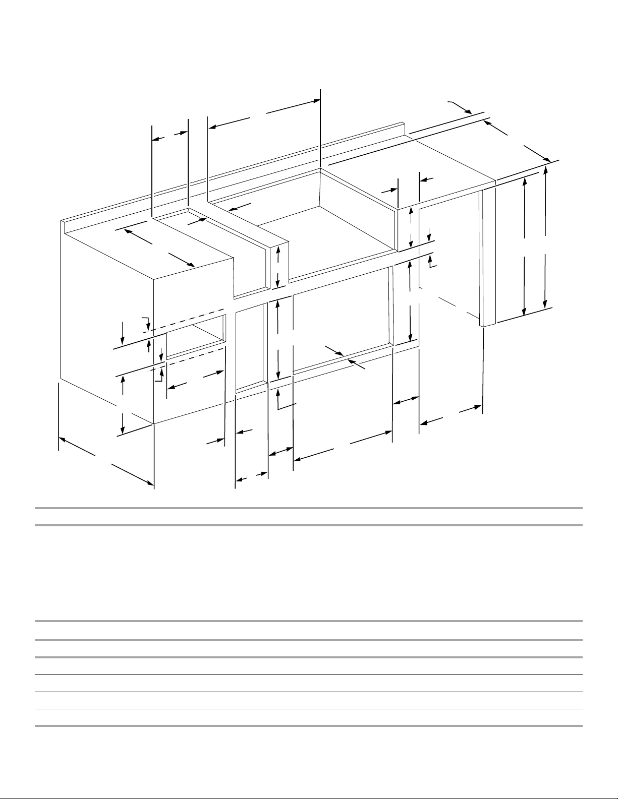
The dimension chart and illustration below include cutout dimensions and minimum spacing requirements for all built-in outdoor
products. The illustration is for reference. The design of your cabinet layout can be personalized, but the dimensions for the cutouts and
minimum spacing must be followed.
3" (7.6 cm) min.
to open hood
C
K
9¹⁄₈"
(23.2 cm)
K
5"
(12.7 cm) min.
C
E
Warming
Drawer
E
12" min.
to any
12" (30.5 cm) min.
to any accessory
accessory
D
A
Grills or
Side
or
Sear
Burners
Utility
or
Trash
Drawer
J
Refreshment Centers
D
Access Doors
20⁷⁄₈" (53.0 cm)
1¹⁄₂"
(3.8 cm) min.
20⁵⁄₈" (52.4 cm)
Refrigerator
or
Ice Maker
L
H
K
2¹⁄₂" (6.4 cm) min.
G
K
K
F
B
M
Minimum Spacing Requirement Between Cutouts - Dimension K
Between 2 or more sets of Access Doors adjacent to each other:
K = 14" (35.6 cm) when 2 adjacent doors are opened to 90 degrees
K = 8" (20.3 cm) when 1 of the adjacent doors is opened to 90 degrees
Between a set of Access Doors and a Trash Drawer, Utility Drawer, Warming Drawer, Refrigerator, or Ice Maker:
K = 8" (20.3 cm) when 1 of the adjacent doors is opened to 90 degrees
Between a Trash Drawer, Utility Drawer, or Warming Drawer:
K = 3" (7.6 cm)
Cabinet Height and Depth Dimensions
Dimension A Minimum Dimension B Minimum
With outdoor refrigerator 37" (94.0 cm) 26" (66.0 cm)
Grill with insulated jacket 36½" (92.7 cm) 27" (68.6 cm)
Grill without insulated jacket 35½" (90.2 cm) 26" (66.0 cm)
7
Page 8

Cutout Dimensions - Built-in Grill
Grill Size Dimension C Dimension D Dimension E
27" (68.6 cm) 29⁵⁄₈" (75.2 cm) 10¾" (27.3 cm) 22⁷⁄₈" (58.1 cm)
36" (91.4 cm) 38⁵⁄₈" (98.1 cm) 10¾" (27.3 cm) 22⁷⁄₈" (58.1 cm)
48" (121.9 cm) 50⁵⁄₈" (128.6 cm) 10¾" (27.3 cm) 22⁷⁄₈" (58.1 cm)
Cutout Dimensions - Built-in Grill with Insulated Jacket
Grill Size Dimension C Dimension D Dimension E
27" (68.6 cm) 33" (83.8 cm) 11¾" (29.8 cm) 24" (61.0 cm)
36" (91.4 cm) 42" (106.7 cm) 11¾" (29.8 cm) 24" (61.0 cm)
48" (121.9 cm) 54" (137.2 cm) 11¾" (29.8 cm) 24" (61.0 cm)
Cutout Dimensions - Built-in Side Burner
Burner Position Dimension C Dimension D Dimension E
Front to Back 13½" (34.3 cm) 10¾" (27.3 cm) 22⁵⁄₈" (57.5 cm)
Side by Side 24½" (62.2 cm) 10¾" (27.3 cm) 16⁷⁄₈" (42.9 cm)
Cutout Dimensions - Built-in Sear Burner
Dimension C Dimension D Dimension E
13½" (34.3 cm) 10⁵⁄₈" (27.0 cm) 22¹¹⁄₁₆" (57.6 cm)
Cutout Dimensions - Built-in Refreshment Center
Dimension C Dimension D Dimension E
30½" (77.5 cm) 10¾" (27.3 cm) 23" (58.4 cm)
Cutout Dimensions - Built-in Access Doors
Door Size Dimension F Dimension L*
18" (45.7 cm) 16³⁄₁₆" (41.1 cm) 1½" (3.8 cm)
27" (68.6 cm) 25¹⁄₈" (63.8 cm) 1½" (3.8 cm)
30" (76.2 cm) 28¹⁄₈" (71.4 cm) 1½" (3.8 cm)
36" (91.4 cm) 34¹⁄₈" (86.7 cm) 1½" (3.8 cm)
48" (121.9 cm) 46¹⁄₈" (117.2 cm) 1½" (3.8 cm)
*Dimension L is the minimum mounting surface area around the opening for mounting the optional door or drawers.
Cutout Dimensions - Outdoor Refrigerator
Dimension G Dimension H
24" (61.0 cm) 35¼" (89.5 cm)
Cutout Dimensions - Outdoor Ice Maker
Dimension G Dimension H
18" (45.7 cm) 34" (86.4 cm) min. to 34½" (87.6 cm) max.
8
Page 9
Cutout Dimensions - Built-in Warming Drawer
Warming Drawer Size Dimension J
24" (61.0 cm) 22½" (57.2 cm)
Cutout Dimensions - Built-in Utility Drawer and Built-in Trash Drawer
Dimension M Dimension L*
12¼" (31.1 cm) 1½" (3.8 cm)
*Dimension L is the minimum mounting surface area around the opening for mounting the optional door or drawers.
Built-in Outdoor Grill Enclosure Ventilation for LP Gas:
An enclosure for an LP gas fuel tank is to be ventilated by
openings at both the top and lower levels of the enclosure.
If converting to LP gas these vents are to be in the enclosure:
An enclosure for use with an LP gas fuel tank for built-in
installation is to have at least one ventilation opening on an
exposed exterior side located within 5" (12.7 cm) of the top is to
be a minimum of 20 in.
within 1" (2.5 cm) of the bottom of the enclosure and the bottom
opening is to be a minimum of 10 in.
2
(129.0 cm2). One ventilation opening
2
(64.5 cm2). All vent
openings are to be unobstructed. Every opening is to be a
minimum of ¹⁄₈" (0.32 cm) wide.
2
20 in.
(129.0 cm2) min.
ventilation both sides
1" (2.5 cm) max.
10 in.2 (64.5 cm2) min.
ventilation both sides
5" (12.7 cm) max.
5" (12.7 cm) max.
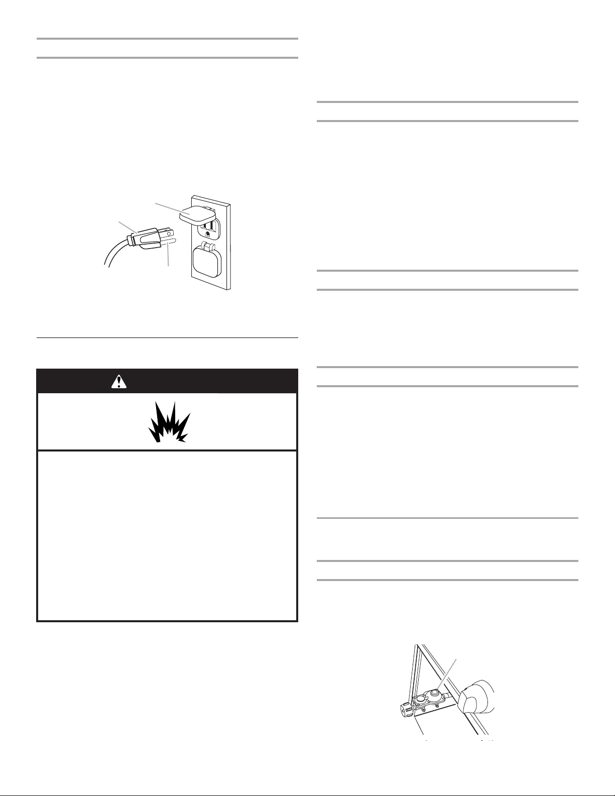
Electrical Requirements
WARNING
Electrical Shock Hazard
Plug into a grounded 3 prong outlet.
Do not remove ground prong.
Do not use an adapter.
Do not use an extension cord.
Failure to follow these instructions can result in death,
fire, or electrical shock.
If codes permit and a separate ground wire is used, it is
recommended that a qualified electrician determine that the
ground path is adequate.
Check with a qualified electrician if you are not sure whether the
side burner is properly grounded.
A 120-volt, 60-Hz, AC-only, 15-amp, fused electrical supply is
required.
It is recommended that a separate circuit servicing only this side
burner be provided.
■ To avoid electrical shock, do not immerse cord or plugs in
water or other liquid.
■ Unplug from the outlet when not in use and before
cleaning. Allow to cool before putting on or taking off
parts.
■ Do not operate any outdoor cooking gas appliance with a
damaged cord, damaged plug, or after the appliance
malfunctions or has been damaged in any manner.
Contact the manufacturer for repair.
■ Do not let the cord hang over the edge of a table or touch
hot surfaces.
■ Do not use an outdoor cooking appliance for purposes
other than intended.
■ When connecting, first connect plug to the outdoor
cooking gas appliance then plug appliance into the outlet.
■ Use only a Ground Fault Interrupter (GFI) protected circuit
with this outdoor cooking gas appliance.
■ Do not remove the ground prong or use with an adapter
of 2 prongs.
The model/serial number rating plate is located on the right-hand
side panel. See the following illustration.
A
A. Model/serial number plate
9
Page 10
Recommended Ground Method
The outdoor side burner, when installed, must be electrically
grounded in accordance with local codes or, in the absence of
local codes, with the National Electrical Code ANSI/NFPA 70, or
Canadian Electrical Code, CSA C22.1.
Copies of the standards listed above may be obtained from:
CSA International
8501 East Pleasant Valley Rd.
Cleveland, Ohio 44131-5575
National Fire Protection Association
One Batterymarch Park
Quincy, Massachusetts 02269
B
A
C
Gas Conversion:
No attempt shall be made to convert the side burner from the gas
specified on the model/serial rating plate for use with a different
gas type without consulting the serving gas supplier. The
conversion kits supplied with the side burner must be used. See
“Gas Conversions” section for instructions.
Gas Pressure Regulator
The gas pressure regulator supplied with this side burner must be
used. The inlet (supply) pressure to the regulator should be as
follows for proper operation:
LP Gas:
Set pressure: 11" (27.9 cm) WCP
Inlet (supply) pressure: 11" to 14" (27.9 cm to 35.5 cm) WCP
Natural Gas:
Set pressure: 4" (10.2 cm) WCP
Inlet (supply) pressure: 7" to 14" (17.8 cm to 35.5 cm)
WCP maximum.
Contact local gas supplier if you are not sure about the inlet
(supply) pressure.
Burner Requirements for High Altitude
A. 3 prong ground plug
B. 3-prong polarized type outdoor GFI outlet
C. Ground prong
Gas Supply Requirements
WARNING
Explosion Hazard
Use a new CSA International approved “outdoor”
gas supply line.
Securely tighten all gas connections.
If connected to LP, have a qualified person make sure
gas pressure does not exceed 11” (28 cm) water
column.
Examples of a qualified person include:
licensed heating personnel,
authorized gas company personnel, and
authorized service personnel.
Failure to do so can result in death, explosion, or fire.
Observe all governing codes and ordinances.
IMPORTANT: This installation must conform with all local codes
and ordinances. In the absence of local codes, installation must
conform with American National Standard, National Fuel Gas
Code ANSI Z223.1 - latest edition or CAN/CGA B149.1 - latest
edition.
IMPORTANT: The side burner must be connected to a regulated
gas supply.
Refer to the model/serial rating plate for information on the type
of gas that can be used. If this information does not agree with
the type of gas available, check with your local gas supplier.
Input ratings shown on the model/serial rating plate are for
elevations up to 2,000 ft (609.6 m).
For elevations above 2,000 ft (609.6 m), ratings are reduced at a
rate of 4% for each 1,000 ft (304.8 m) above sea level. Orifice
conversion is required. See “Assistance or Service” section to
order.
Gas Supply Line Pressure Testing
Testing above ½ psi (3.5 kPa) or 14" (35.5 cm) WCP (gauge):
The side burner and its individual shutoff valve must be
disconnected from the gas supply piping system during any
pressure testing of that system at test pressures greater than
½ psi (3.5 kPa).
Testing below ½ psi (3.5 kPa) or 14" (35.5 cm) WCP (gauge) or
lower:
The side burner must be isolated from the gas supply piping
system by closing its individual manual shutoff valve during any
pressure testing of the gas supply piping system at test
pressures equal to or less than ½ psi (3.5 kPa).
Gas Connection Requirements
For Models Equipped for LP Gas
20 lb LP Gas Fuel Tank
This side burner is equipped for use with a 20 lb LP gas fuel tank
(fuel tank not supplied). A gas pressure regulator/hose assembly
is supplied.
It is also design-certified by CSA International for local LP gas
supply or for Natural gas with appropriate conversion.
A
A. Gas pressure regulator/hose assembly
10
Page 11
The 20 lb LP gas fuel tank must be mounted and secured.
A
A
Door Style Tank Tray
1. Open cabinet doors.
2. Pull out the tank tray.
Tank t r a y
3. Place the 20 lb LP gas fuel tank bottom collar into the
mounting hole in the tank tray.
4. Tighten the locking screw against the bottom collar of the
20 lb LP gas fuel tank to secure.
A
B C
A. Locking screw
B. Mounting hole
C. Bottom collar
5. Slide tank tray back into the cabinet.
6. Close cabinet doors.
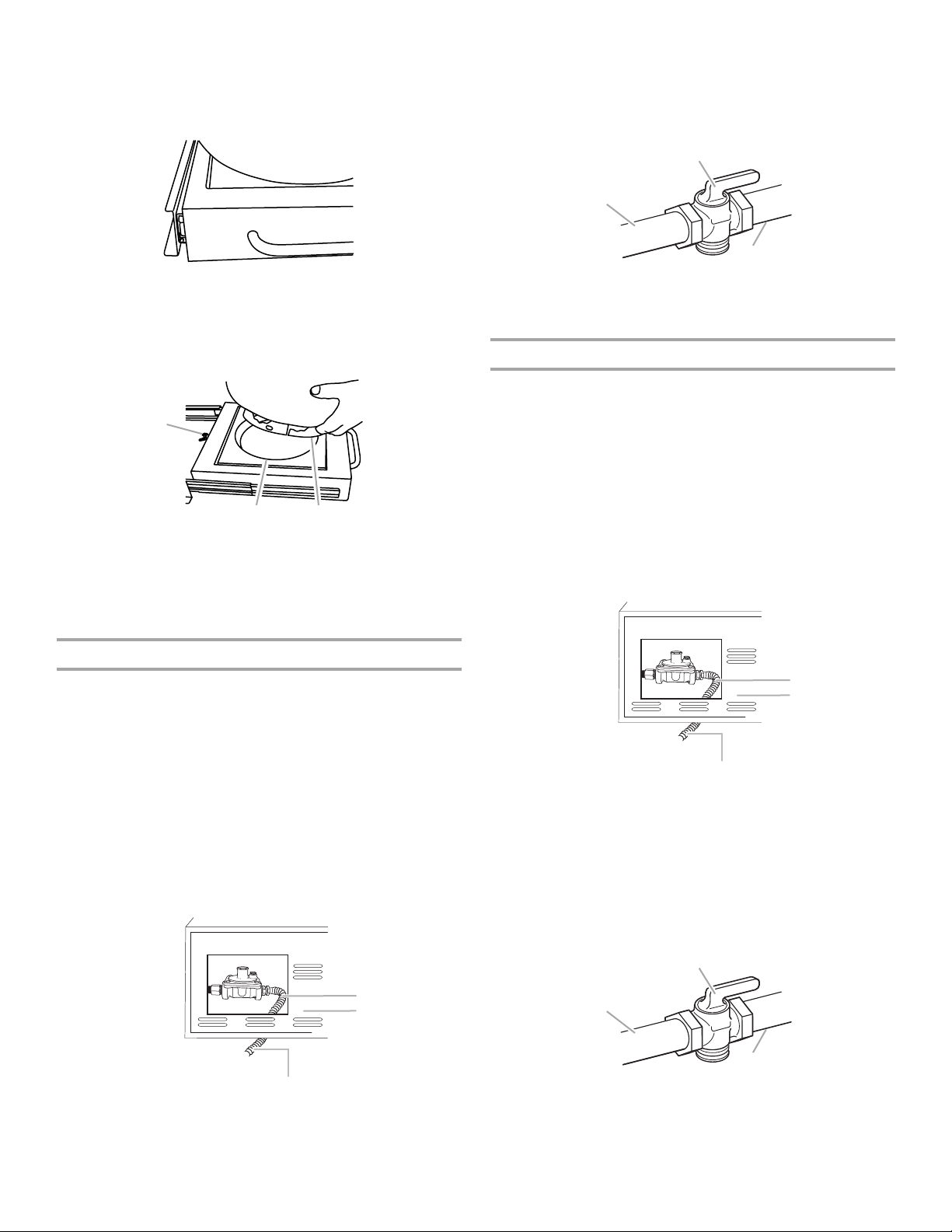
The gas supply line shall be equipped with an approved shutoff
valve. This valve should be located in the same area as the side
burner and should be in a location that allows ease of opening
and closing. Do not block access to the shutoff valve. The valve
is for turning on or shutting off gas to the side burner.
B
A
C
A. Gas supply line
B. Shutoff valve “open” position
C. To side burner
Natural Gas Conversion
Conversion must be made by a qualified gas technician. The
qualified Natural gas technician shall provide the Natural gas
supply to the selected side burner location in accordance with
the National Fuel Gas Code ANSI Z223.1/NFPA 54 - latest
edition, and local codes. For conversion to Natural gas, the
Natural gas conversion kit supplied with the side burner must be
used.
IMPORTANT: The gas installation must conform with local
codes, or in the absence of local codes, with the National Fuel
Gas Code, ANSI Z223.1/NFPA 54 - latest edition.
To convert to Natural gas, the Natural Gas Conversion Kit
supplied with the side burner must be used. Follow instructions
for converting to Natural gas in the “Gas Conversions” section.
Local LP Gas Supply Conversion
Conversion must be made by a qualified gas technician. The
qualified gas technician shall provide the gas supply to the
selected side burner location in accordance with the National
Fuel Gas Code ANSI Z223.1/NFPA 54 - latest edition, and local
codes. For conversion to local LP, the convertible regulator in the
conversion kit supplied with the side burner must be used.
IMPORTANT: The gas installation must conform with local
codes, or in the absence of local codes, with the National Fuel
Gas Code, ANSI Z223.1/NFPA 54 - latest edition. The qualified
LP gas technician shall provide the LP gas supply to the selected
side burner location in accordance with the National Fuel Gas
Code, ANSI Z223.1/NFPA 54 and local codes.
Follow instructions for converting to local LP gas in the “Gas
Conversions” section.
B
C
A. New CSA International approved
“outdoor” flexible gas supply line
B. Rear of side burner
C. To local LP gas supply
B
C
A. New CSA International approved
“outdoor” flexible gas supply line
B. Rear of side burner
C. To Natural gas supply
The gas supply line shall be equipped with an approved shutoff
valve. This valve should be located in the same area as the side
burner and should be in a location that allows ease of opening
and closing. Do not block access to the shutoff valve. The valve
is for turning on or shutting off gas to the side burner.
B
A
C
A. Gas supply line
B. Shutoff valve “open” position
C. To side burner
11
Page 12
Gas Connection Requirements
For Models Equipped for Natural Gas
Natural Gas
Built-in side burner models are equipped for use with Natural
gas. They are design-certified by CSA International for LP
(propane or butane) gases with appropriate conversion.
Built-in models are set for Natural gas use and have a pressure
regulator with ½" female pipe threads.
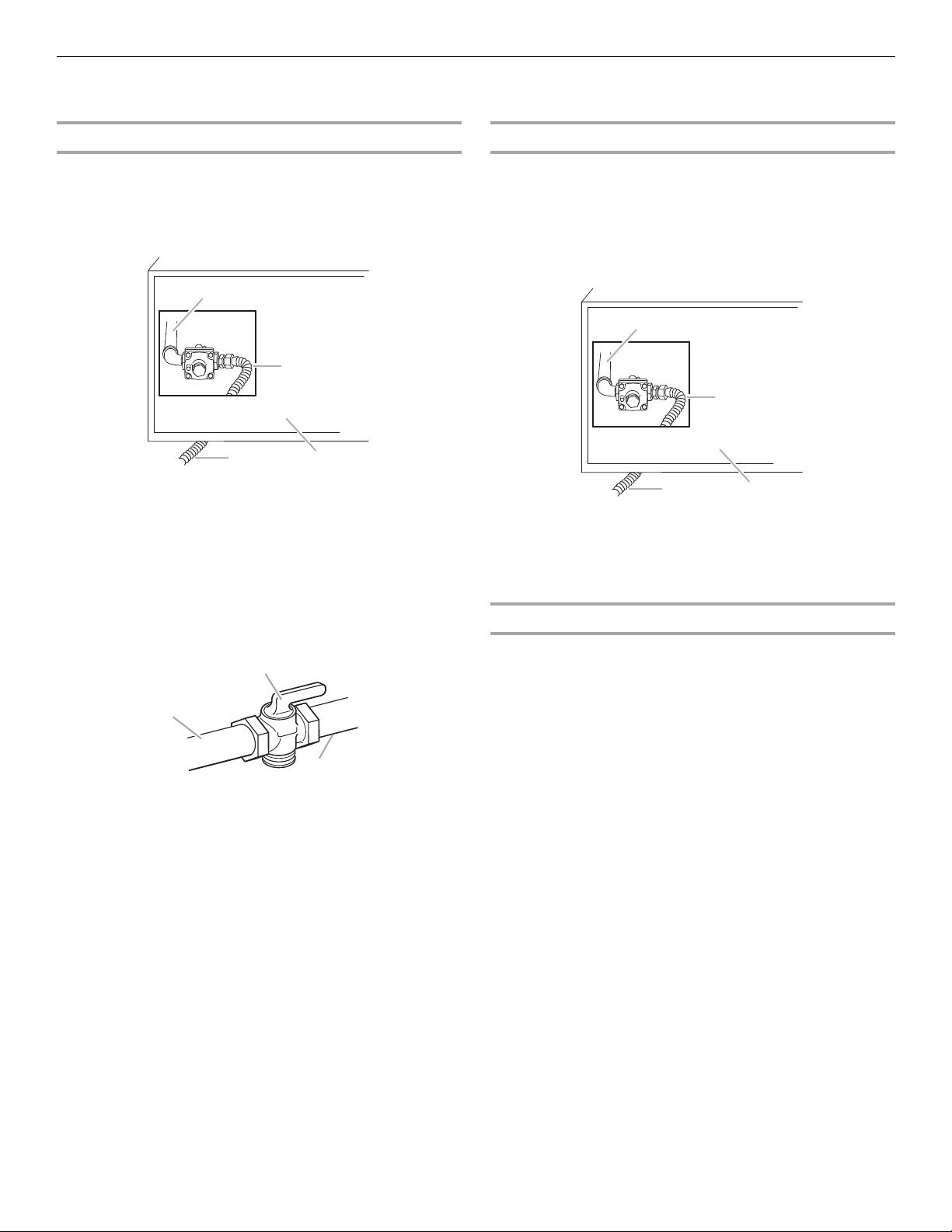
A
B
D
A. Side burner gas pipe
B. New CSA International approved
“outdoor” flexible gas supply line
C. Rear of side burner
D. To Natural gas supply
The supply line shall be equipped with an approved shutoff valve.
This valve should be located in the same area as the side burner
and should be in a location that allows ease of opening and
closing. Do not block access to the shutoff valve. The valve is for
turning on or shutting off gas to the side burner.
B
C
LP Gas Conversion Using a Local LP Gas Supply
Conversion must be made by a qualified person. A qualified
Natural gas technician shall provide the LP gas supply to the
selected side burner location in accordance with the National
Fuel Gas Code ANSI Z223.1/NFPA 54 - latest edition, and local
codes.
To convert to LP gas, the LP Gas Conversion Kit Part Number
W10118099 must be used. Follow instructions included with kit.
A
B
D
A. Side burner gas pipe
B. New CSA International approved
“outdoor” flexible gas supply line
C. Rear of side burner
D. To local gas supply
C
LP Gas Conversion Using a 20 lb LP Gas Fuel Tank
To convert to LP gas, the LP Gas Conversion Kit Part Number
W10118099 must be used. Follow instructions included with kit.
A 20 lb LP gas fuel tank must be purchased separately.
A
C
A. Gas supply line
B. Shutoff valve “open” position
C. To side burner
12
Page 13
INSTALLATION INSTRUCTIONS
A
B
C
D
Built-in Outdoor Side Burner Installation
WARNING
Excessive Weight Hazard
Use two or more people to move and install side
burner.
Failure to do so can result in back or other injury.
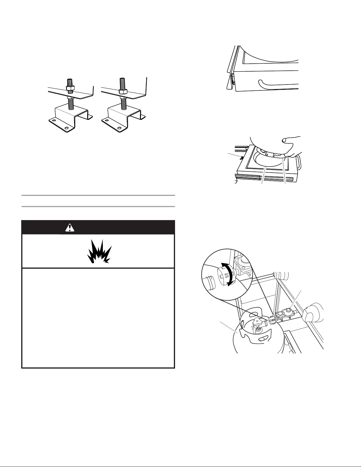
3. Remove the top nuts (4) from the tank tray assembly and lift
the tank tray off of the mounting brackets.
E
■ Unpack side burner. Remove all packaging materials and
remove side burner from carton.
■ Place side burner into outdoor enclosure, but leave enough
room in back to connect to gas supply and electrical single
prong plug-in.
Install Tank Tray for 20 lb LP Gas Fuel Tank
For Models Equipped for Use with a 20 lb LP Tank
1. Position the tank tray for 20lb LP gas fuel tank in the island
cabinet.
2¹⁄₄"
centerline of
tank tray
20⁵⁄₈"
(52.4 cm)
18³⁄₈"
(46.7 cm)
(5.7 cm)
A
B
A. Top nut
B. Tank tray
C. Bottom nut
D. Bolt
E. Mounting bracket
4. Install the tank tray mounting brackets to the base or floor of
the island using the proper size and type of mounting
hardware (not supplied). Tighten mounting hardware.
A
B
C
3"
(7.6 cm)
A. Screw (Use proper screw for island floor material.)
B. Lock washer
C. Flat washer
5. Pre-adjust each of the bottom nuts on the mounting brackets
to 3" (7.6 cm) from the base of the island to the top of the
nuts.
6. Remount the tank tray back onto the mounting brackets.
Replace the 4 top nuts but do not tighten.
Dimension A Dimension B
Front to back burner 8³⁄₃₂" (20.6 cm) 16³⁄₁₆" (41.1 cm)
Side by side burner 12⁹⁄₁₆" (31.9 cm) 25¹⁄₈" (63.8 cm)
2. Square the tank tray mounting brackets and mark the
mounting hole locations in the island base.
A
B
C
D
A. 20 lb LP gas fuel tank
B. Tank tray for 20 lb gas fuel tank
C. Top nut (do not tighten)
D. Mounting bracket
13
Page 14
7. The tank tray for the 20 lb LP gas fuel tank must be adjusted
so that the bottom of the tank tray is ¹⁄₈" (0.32 cm) above the
cabinet door opening and is level. The top nut on each of the
mounting brackets is to be loose. Turn the bottom nuts
counterclockwise to raise the tank tray and turn the bottom
nuts clockwise to lower the tank tray. When the tank tray is
level and slides in and out without touching the cabinet door
opening at the bottom or top with the 20 lb LP tank installed,
tighten the top nuts against the adjustment flange.
A
B
To Install the 20 lb LP Gas Fuel Tank:
1. Open cabinet doors.
2. Pull out the tank tray.
Tank tr a y
3. Place the 20 lb LP gas fuel tank bottom collar into the
mounting hole in the tank tray.
4. Tighten the locking screw against the bottom collar of the
20 lb LP gas fuel tank to secure.
A. Top nut loosened
B. Top nut tightened
NOTE: A bracket or shelf (not supplied) that is large enough
to keep a second 20 lb LP gas fuel tank from being stored in
the storage area under the side burner is required to be
mounted inside the island.
Make Gas Connection
Gas Connection to a 20 lb LP Gas Fuel Tank
WARNING
Explosion Hazard
Use a new CSA International approved “outdoor”
gas supply line.
Securely tighten all gas connections.
If connected to LP, have a qualified person make sure
gas pressure does not exceed 11” (28 cm) water
column.
Examples of a qualified person include:
licensed heating personnel,
authorized gas company personnel, and
authorized service personnel.
Failure to do so can result in death, explosion, or fire.
A
B C
A. Locking screw
B. Mounting hole
C. Bottom collar
5. Screw the gas pressure regulator/hose assembly to the 20 lb
LP gas fuel tank as shown. (To disconnect, turn off the gas
supply to the 20 lb LP gas fuel tank, then unscrew the gas
pressure regulator/hose assembly from the 20 lb LP gas fuel
tank as shown.)
connect
disconnect
B
A
A. 20 lb LP gas fuel tank
B. Gas pressure regulator/hose assembly
If converting to local LP or Natural gas, follow the instructions in
the “Gas Conversions” section.
IMPORTANT: A 20 lb LP gas fuel tank must be purchased
separately.
IMPORTANT: The gas pressure regulator/hose assembly
supplied with the side burner must be used. Replacement gas
pressure regulator/hose assembly specific to your model, is
available from your outdoor side burner dealer.
14
6. Turn on the gas supply. Wait a few minutes for gas to move
through the gas line.
7. Test all connections by brushing on an approved
noncorrosive leak-detection solution. Bubbles will show a
leak. Correct any leak found.
8. Slide tank tray back into the cabinet.
9. Go to “Plug in Side Burner” in this section.
Page 15
Gas Connection to Natural Gas or Local LP Gas
A
2. Open the manual shutoff valve in the gas supply line. The
valve is open when the handle is parallel to the gas pipe.
WARNING
Explosion Hazard
Use a new CSA International approved “outdoor”
gas supply line.
Securely tighten all gas connections.
If connected to LP, have a qualified person make sure
gas pressure does not exceed 11” (28 cm) water
column.
Examples of a qualified person include:
licensed heating personnel,
authorized gas company personnel, and
authorized service personnel.
Failure to do so can result in death, explosion, or fire.
This installation must conform with local codes and ordinances.
In the absence of local codes, installations must conform with
either the National Fuel Gas Code ANSI Z223.1 - latest edition, or
CAN/CGA-B149.1 Natural Gas and Propane installation code.
Copies of the standards listed above may be obtained from:
CSA International
8501 East Pleasant Valley Rd.
Cleveland, Ohio 44131-5575
National Fire Protection Association
One Batterymarch Park
Quincy, Massachusetts 02269
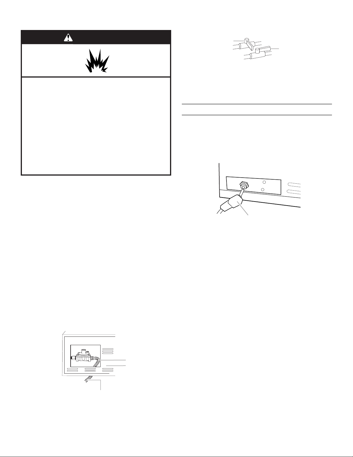
1. Make gas connections.
A combination of pipe fittings must be used to connect the
side burner to the existing gas line.
■ If local codes permit, use an outdoor flexible stainless
steel tubing gas connector, design-certified by CSA
International, to connect the side burner to the rigid gas
supply line. A ⁵⁄₈" diameter line is recommended. Using a
wrench to tighten, connect the gas supply to the side
burner. Use pipe-joint compound on all non-flared male
threads. Do not kink or damage the flexible connector
when moving the side burner.
■ Pipe-joint compounds suitable for use with LP gas must
be used. Do not use TEFLON®† tape.
A
B
A. Closed valve
B. Open valve
3. Test all connections by brushing on an approved
noncorrosive leak-detection solution. Bubbles will show a
leak. Correct any leak found.
Plug in Side Burner
NOTE: This built-in outdoor side burner comes with a large
5000 mAmp power transformer/plug assembly for the side
burner igniters. Follow the instructions for plugging in and
mounting the power transformer. Keep any electrical supply cord
away from any heated surfaces.
1. Plug the single-prong plug into the receptacle on the left
underside of the side burner.
A
A. Single-prong plug
2. Locate or build a non-combustible surface inside the island
cabinet to mount the power transformer. It must be to the left
side of the side burner at a minimum of 3" (7.6 cm) from the
side and 4" (10.2 cm) below the bottom of the side burner.
3. Mount the power transformer to the mounting surface using
4 #8 screws (not supplied) that are the proper type and length
for the transformer and the mounting surface. It must be
mounted with the wire for the single-prong plug upward or
toward the side burner.
NOTE: The cord must be properly mounted with a cord
retention device so that its 3-prong plug will not touch the
ground when it is unplugged.
B
C
A. New CSA International approved
“outdoor” flexible gas supply line
B. Rear of side burner
C. To Natural gas or Local LP gas supply
†®TEFLON is a registered trademark of E.I. Du Pont De Nemours and Company.
15
Page 16

4. Gently slide the side burner completely into the outdoor
enclosure.
Assemble Cooking Area
WARNING
Electrical Shock Hazard
Plug into a grounded 3 prong outlet.
Do not remove ground prong.
Do not use an adapter.
Do not use an extension cord.
Failure to follow these instructions can result in death,
fire, or electrical shock.
5. Plug 3-prong power cord plug into a grounded 3-prong GFI
outlet.
■ To avoid electrical shock, do not immerse cord or plugs in
water or other liquid.
■ Unplug from the outlet when not in use and before
cleaning. Allow to cool before putting on or taking off
parts.
■ Do not operate any outdoor cooking gas appliance with a
damaged cord, damaged plug, or after the appliance
malfunctions or has been damaged in any manner.
Contact the manufacturer for repair.
■ Do not let the cord hang over the edge of a table or touch
hot surfaces.
■ Do not use an outdoor cooking appliance for purposes
other than intended.
■ When connecting, first connect plug to the outdoor
cooking gas appliance then plug appliance into the outlet.
■ Use only a Ground Fault Interrupter (GFI) protected circuit
with this outdoor cooking gas appliance.
■ Do not remove the ground prong or use with an adapter
of 2 prongs.
1. Lift off cover and grate and set aside.
A
B
A. Cover
B. Grate
2. Remove packing from around burners.
3. Reinstall grate.
4. Dispose of/recycle all packaging materials.
5. Gently slide side burner completely into outdoor enclosure.
6. Go to the “Check and Adjust the Burners” section.
16
Page 17

GAS CONVERSIONS
For Models Equipped for Use with a 20 lb LP gas Tank
NOTE: Models that are equipped for Natural gas require Gas Conversion Kit Part Number W10118099 for conversion to LP gas. Use
the conversion instructions included in the kit. See “Assistance or Service” section for information on ordering.
Tools and Parts for Gas Conversion
Gather the required tools and parts before starting installation.
Read and follow the instructions provided with any tools listed
here.
Tools ne ed ed
■ Phillips screwdriver
■ Pipe wrench
■ Adjustable wrench
■ 10 mm socket and wrench
or 10 mm nut driver
■ Thin flat-blade screwdriver
■ Pliers
■ Pipe thread sealant
certified for LP gas
Parts supplied
■ Brass connector
■ Convertible regulator 4" W.C. Natural, 11" W.C. LP
■ Natural gas orifices
IMPORTANT: Gas conversions must be done by a qualified
installer. Before proceeding with conversion, shut off the gas
supply to the appliance prior to disconnecting the electrical
power.
This kit is designed for use from sea level up to 2000 ft elevation.
For higher elevations contact KitchenAid at 1-800-422-1230 in
the U.S.A. or call 1-800-607-6777 in Canada.
WARNING
Conversion to a Local LP Gas Supply
Installation of the regulator
1. Turn off the main gas supply valve.
2. Unplug side burner or disconnect power.
3. Disconnect 20 lb LP gas fuel tank (if present).
4. Turn off all burner control valves.
5. Remove rear cover and 2 screws.
6. Use adjustable wrench to remove LP hose regulator from
brass elbow. Use adjustable wrench to remove brass elbow.
A
B
C
Explosion Hazard
Use a new CSA International approved “outdoor”
gas supply line.
Securely tighten all gas connections.
If connected to LP, have a qualified person make sure
gas pressure does not exceed 11” (28 cm) water
column.
Examples of a qualified person include:
licensed heating personnel,
authorized gas company personnel, and
authorized service personnel.
Failure to do so can result in death, explosion, or fire.
D
A. Manifold
B. Brass elbow
C. Rear of side burner
D. Gas pressure regulator/hose assembly
7. Apply pipe sealant to the threads of the brass connector. Use
pipe thread sealant that is certified for use with LP gas.
8. Use adjustable wrench to install brass connector (supplied) to
manifold fitting.
NOTE: The arrow on the regulator must be pointing toward
the brass connector.
17
Page 18

9. Use pipe wrench to install the convertible regulator. Brass
cap will be facing up when tight.
A
A. Brass connector
B. Convertible regulator
10. To set the appliance regulator for LP gas, use adjustable
wrench to remove the brass cap on the convertible regulator.
11. Examine the stem on the brass cap. The letters “NAT” should
be showing on the end of the plastic stem farthest away from
the brass cap.
12. Remove stem from cap, turn it over and snap stem back into
the cap so the letters “LP” are at the end of the stem farthest
away from the brass cap.
B
Conversion from LP Gas to Natural Gas
Installation of the regulator
1. Turn off the main gas supply valve.
2. Unplug side burner or disconnect power.
3. Disconnect 20 lb LP gas fuel tank (if present).
4. Turn off all burner control valves.
5. Remove rear cover and 2 screws.
6. Use adjustable wrench to remove LP hose regulator from
brass elbow. Use adjustable wrench to remove brass elbow.
A
B
C
LP
13. Use adjustable wrench to reinstall cap onto regulator.
Make Side Burner Connections
Connect Local LP Gas Supply
1. Use pipe wrench to connect certified ½" (1.3 cm) gas supply
pipe to inlet side of regulator from Fixed LP gas supply
according to local codes requirements. Use pipe thread
sealant that is certified for use with LP gas at connections
where required. There must be a certified manual shutoff
valve in the gas supply line near the side burner for easy
access.
2. Turn on the gas supply to the side burner.
3. Test all connections by brushing on an approved
noncorrosive leak-detection solution. Bubbles will show a
leak. Correct any leaks found.
Record Conversion
In the last page of the Use and Care Guide, write “Converted to
Local LP Gas Supply.” Also record the conversion date and the
technician/company that performed the conversion.
D
A. Manifold
B. Brass elbow
C. Rear of side burner
D. Gas pressure regulator/hose assembly
7. Apply pipe sealant to the threads of the brass connector. Use
pipe thread sealant that is certified for use with LP gas.
8. Use adjustable wrench to install brass connector (supplied) to
manifold fitting.
NOTE: The arrow on the regulator must be pointing toward
the brass connector.
18
Page 19

9. Use pipe wrench to install the convertible regulator. Brass
cap will be facing up when tight.
A
A. Brass elbow
B. Convertible regulator
B
10. To make sure the regulator is set for Natural gas, use
adjustable wrench to remove brass cap on appliance
regulator.
11. Examine the stem on the brass cap. If the letters “NAT” are
not showing on the end of the plastic stem farthest away from
the brass cap, remove stem from cap, turn it over and snap
stem back into the cap so the letters “NAT” are at the end of
the stem farthest away from the brass cap.
NAT
4. Use 10 mm socket and wrench or 10 mm nut driver to install
the new 2.1 mm orifices supplied with this kit.
NOTE: The number 2.1 is stamped on the orifice for
identification.
5. Repeat the procedure for the other burner.
6. Replace the burner top and caps. Align the notches in the
bottom of the burner top with the tabs on the burner base
and twist until the burner top is seated on the burner base.
You will feel it drop into the deep notch.
A
A. Burner top notches
B. Burner base tabs
B
7. Replace the side burner grates.
Hook up to Natural gas and Leak Test
1. Use pipe wrench to connect certified ¹⁄₂" (1.3 cm) gas supply
pipe to inlet side of regulator from Natural gas supply
according to local codes requirements. Use pipe thread
sealant that is certified for use with LP gas at connections
where required. There must be a certified manual shutoff
valve in the gas supply line near the grill for easy access.
2. Turn on the gas supply to the grill.
3. Test all connections using an approved noncorrosive leak-
detection solution. Bubbles will show a leak. Correct any leak
found.
12. Reinstall cap onto convertible regulator.
Change the Side burner orifices
1. Remove the side burner grates.
2. Remove the burner caps. The caps are interlocked to the
burner base. Twist and lift the burner caps to remove.
3. Use 10 mm socket and wrench or 10 mm nut driver to
remove the brass orifices from inside the burner base.
Record Conversion
1. The appliance nameplate is located inside the grill cabinet on
the right-hand cabinet side. With a permanent marker, check
the box next to “Natural gas” and mark through “LP Propane.”
In the last page of the Use and Care Guide, write “Converted to
Natural Gas.” Also record the conversion date and the
technician/company that performed the conversion.
NOTE: Place LP gas parts in plastic parts bag for future use and
keep with pack containing literature.
Check and Adjust the Burners
The burners are tested and factory-set for most efficient
operation. However, variations in gas supply and other conditions
may make minor adjustments to low flame setting necessary.
It is recommended that a qualified person make burner
adjustments.
³⁄₄" - 1"
(1.9 - 2.5 cm)
on all burner ports
with burners on
"HI" setting
19
Page 20

Low Flame Adjustment
If flame goes out on the “LO” setting, the low flame setting must
be adjusted.
1. Turn off the valve and wait until burners are cool.
2. Light side burner using information in the “Outdoor Side
Burner Use” section.
3. Turn burner to its lowest setting and remove knob.
4. Hold valve stem with pliers and insert a small flat-blade
screwdriver into the shaft.
5. Watch the flame and slowly turn the screwdriver
counterclockwise.
USING YOUR OUTDOOR SIDE BURNER
Inspect the LP Gas Fuel Tank Supply Hose
Inspect the gas pressure regulator/hose assembly before each
use.
1. Open the cabinet door and slide 20 lb LP gas fuel tank out.
2. Inspect the entire gas pressure regulator/hose assembly for
cuts, abrasions, or excessive wear.
3. If necessary, replace the gas pressure regulator/hose
assembly before using the side burner.
Contact the dealer and use only replacement hoses specified for
use with the side burner.
A
6. Adjust flame to minimum stable flame.
A
B
C
A. Valve stem
B. Small flat-blade screwdriver
C. Pliers
7. Replace the control knob and turn off the burner.
8. Repeat steps 3 through 7 for each burner if needed.
Lighting Your Side Burner
WARNING
Burn Hazard
Do not let the burner flame extend beyond the edge of
the pan.
Doing so can result in burns.
A. Gas pressure regulator/hose assembly
Prepare the Gas Supply
1. Remove outdoor side burner cover.
2. Make sure the control knobs are all turned to the OFF
position.
Turn the Gas Supply On
1. For outdoor side burners using a 20 lb LP gas fuel tank:
Slowly open the tank valve.
NOTE: If flow limiting device activates, your side burner may
not light. If your side burner does light, the flames will be low
and will not heat properly. Turn 20 lb LP gas fuel tank valve
and all control knobs off and wait 30 seconds. After shutting
off the 20 lb LP gas fuel tank, very slowly open tank valve and
wait 5 seconds before lighting.
2. For outdoor side burners using gas supply source other than
20 lb LP gas fuel tank:
Open the manual shutoff valve in the gas supply line. The
valve is open when the handle is parallel to the gas pipe.
WARNING
Food Poisoning Hazard
Do not let food sit for more than one hour before or
after cooking.
Doing so can result in food poisoning or sickness.
1. Remove the side burner cover. Do not light burners with the
cover on.
2. Do not lean over the side burner.
3. Push in and turn the control knob to LITE/HI and hold in.
4. You will see the igniter glow. When burner is lit, release the
knob. Turn knob to desired setting.
5. Repeat for the other burner as needed.
IMPORTANT: If burner does not light immediately, turn the
burner knob to OFF and wait 5 minutes before relighting.
20
Page 21

Manually lighting the side burner
1. Remove the outdoor side burner cover.
2. Remove the manual lighting extension (see following
illustration) and attach a match to the split ring.
3. Strike the match to light it.
4. Guide the match to the burner you wish to light.
OUTDOOR SIDE BURNER CARE
General Cleaning
IMPORTANT: Before cleaning, make sure all controls are off and
the side burner is cool. Always follow label instructions on
cleaning products.
For routine cleaning, wash with soap and water using a soft cloth
or sponge. Rinse with clean water and dry at once with a soft,
lint-free cloth to avoid spots and streaks.
Do not use steel wool to clean the side burner, as it will scratch
the surface.
To avoid weather damage to finish, use stainless steel side
burner cover.
STAINLESS STEEL
IMPORTANT: To avoid damage to stainless steel surfaces, do not
use soap-filled scouring pads, abrasive cleaners, Cooktop
Polishing Creme, steel wool, gritty wash cloths or paper towels.
To avoid damage to the finish, cleaners should not contain
chlorine.
Food spills should be cleaned as soon as entire side burner is
cool. Spills may cause permanent discoloration.
Cleaning Method:
■ Rub in direction of grain to avoid scratching or damaging the
surface.
■ KitchenAid
4396920 (not included) or KitchenAid® Stainless Steel Wipes
Part Number 8212510 (not included):
See “Assistance or Service” section to order.
■ Liquid detergent or all-purpose cleaner:
■ Rinse with clean water and dry with soft, lint-free cloth.
■ Vinegar to remove hard water spots.
■ Glass cleaner to remove fingerprints.
®
Stainless Steel Cleaner and Polish Part Number
5. Do not lean over the side burner. Push in and turn the burner
knob to LITE/HI for the burner closest to the lit match. The
burner will light immediately. When burner is lit, turn knob to
desired setting.
6. Repeat for each of the other burners as needed.
7. Remove match and replace manual lighting extension inside
its holder.
IMPORTANT:
If burner does not light immediately, turn the burner knob to OFF
and wait 5 minutes before relighting.
If any burners do not light after attempting to manually light them,
contact the KitchenAid Customer eXperience Center. See the
“Assistance or Service” section.
EXTERIOR
The quality of this material resists most stains and pitting,
providing that the surface is kept clean, polished and covered.
■ Apply stainless steel polish to all non-cooking areas before
first use. Reapply after each cleaning to avoid permanent
damage to surface.
■ Cleaning should always be followed by rinsing with clean
warm water.
■ Wipe the surface completely dry with a soft cloth.
■ For tough spots or baked-on grease, use Kitchen and BBQ
Grill Degreaser Part Number 31617, a commercial degreaser
designed for stainless steel.
See “Assistance or Service” section to order.
INTERIOR
Discoloration of stainless steel on these parts is to be expected,
due to intense heat from the burners. Always rub in the direction
of the grain. Cleaning should always be followed by rinsing with
clean, warm water.
Cleaning Method:
■ Liquid detergent or all-purpose cleaner.
■ Rinse with clean water and dry completely with a soft, lint-
free cloth.
■ A heavy-duty scrub sponge can be used with mild cleaning
products.
■ For small, difficult-to-clean areas, use Kitchen and BBQ Grill
Degreaser Part Number 31617, a commercial degreaser
designed for stainless steel.
See “Assistance or Service” section to order.
21
Page 22

SIDE BURNER CAPS AND GRATE
KNOBS AND FLANGE AREA AROUND KNOBS
Cleaning Method:
■ Clean with a brass bristle brush.
■ Wash grate using mild detergent, warm water and degreaser.
■ Rinse with clean water and dry with soft, lint-free cloth.
■ KitchenAid
4396920 (not included) or KitchenAid
Part Number 8212510 (not included):
See “Assistance or Service” section to order.
®
Stainless Steel Cleaner and Polish Part Number
®
Stainless Steel Wipes
TROUBLESHOOTING
Try the solutions suggested here first in order to avoid the cost of an unnecessary service call.
Nothing will operate
■ Is the main or regulator gas shutoff valve in the off
position?
See the Installation Instructions.
■ Is the gas supply properly connected?
Contact a trained repair specialist or see Installation
Instructions.
IMPORTANT: To avoid damage to knobs or to flange area around
knobs, do not use steel wool, abrasive cleaners, or oven cleaner.
Do not soak knobs.
Cleaning Method:
■ Mild detergent, a soft cloth and warm water.
■ Rinse and dry.
CONTROL PANEL GRAPHICS
IMPORTANT: To avoid damage to control panel graphics, do not
use steel wool, abrasive cleaners or oven cleaner.
Do not spray cleaner directly onto panel.
Cleaning Method:
■ Clean around the burner labels gently; scrubbing may remove
printing.
■ Mild detergent, soft cloth and warm water.
■ Rinse and dry.
WARNING
ASSISTANCE OR SERVICE
Before calling for assistance or service, please check
“Troubleshooting.” It may save you the cost of a service call. If
you still need help, follow the instructions below.
When calling, please know the purchase date and the complete
model and serial number of your appliance. This information will
help us to better respond to your request.
Electrical Shock Hazard
Plug into a grounded 3 prong outlet.
Do not remove ground prong.
Do not use an adapter.
Do not use an extension cord.
Failure to follow these instructions can result in death,
fire, or electrical shock.
■ Is the 5,000 mAmp power supply cord unplugged?
Plug into a grounded 3 prong outlet.
■ Has a household fuse blown, or has a circuit breaker
tripped?
Replace the fuse or reset the circuit breaker. If the problem
continues, call an electrician.
If you need replacement parts
If you need to order replacement parts, we recommend that you
use only factory specified parts. These factory specified parts will
fit right and work right because they are made with the same
precision used to build every new KITCHENAID
To locate factory specified parts in your area, call us or your
nearest KitchenAid designated service center.
®
appliance.
22
Page 23

In the U.S.A.
Call the KitchenAid Customer eXperience Center toll free:
1-800-422-1230.
Our consultants provide assistance with:
■ Features and specifications on our full line of appliances.
■ Installation information.
■ Use and maintenance procedures.
■ Accessory and repair parts sales.
■ Specialized customer assistance (Spanish speaking, hearing
impaired, limited vision, etc.).
■ Referrals to local dealers, repair parts distributors and service
companies. KitchenAid designated service technicians are
trained to fulfill the product warranty and provide afterwarranty service, anywhere in the United States.
To locate the KitchenAid designated service company in your
area, you can also look in your telephone directory Yellow
Pages.
For further assistance
If you need further assistance, you can write to KitchenAid with
any questions or concerns at:
KitchenAid Brand Home Appliances
Customer eXperience Center
553 Benson Road
Benton Harbor, MI 49022-2692
Please include a daytime phone number in your correspondence.
Accessories
Kitchen and BBQ Grill Degreaser
Order Part Number 31617
KitchenAid® Stainless Steel Cleaner and Polish
Order Part Number 4396920
KitchenAid® Stainless Steel Wipes
Order Part Number 8212510
In Canada
Call the KitchenAid Canada Customer eXperience Centre toll
free: 1-800-807-6777.
Our consultants provide assistance with:
■ Features and specifications on our full line of appliances.
■ Use and maintenance procedures.
■ Accessory and repair parts sales.
■ Referrals to local dealers, repair parts distributors and service
companies. KitchenAid Canada designated service
technicians are trained to fulfill the product warranty and
provide after-warranty service, anywhere in Canada.
For further assistance
If you need further assistance, you can write to KitchenAid
Canada with any questions or concerns at:
Customer eXperience Centre
KitchenAid Canada
1901 Minnesota Court
Mississauga, Ontario L5N 3A7
Please include a daytime phone number in your correspondence.
KITCHENAID® OUTDOOR PRODUCT WARRANTY
LIMITED WARRANTY
For one year from the date of purchase, when this outdoor product is operated and maintained according to instructions attached to or
furnished with the product, KitchenAid brand of Whirlpool Corporation or Whirlpool Canada LP (hereafter “KitchenAid”) will pay for
Factory Specified Parts and repair labor to correct defects in materials or workmanship. Service must be provided by a KitchenAid
designated service company. This limited warranty is valid only in the United States or Canada and applies only when the outdoor
product is used in the country in which it was purchased. Outside the 50 United States and Canada, this limited warranty does not
apply. Proof of original purchase date is required to obtain service under this limited warranty.
SECOND THROUGH FIFTH YEAR LIMITED WARRANTY ON PARTS ON GRILLS ONLY
In the second through fifth years from the date of purchase when this grill is operated and maintained according to instructions
attached to or furnished with the product, KitchenAid will pay for Factory Specified Parts to correct defects in materials or
workmanship.
LIFETIME LIMITED WARRANTY ON STAINLESS STEEL COMPONENTS ON GRILLS ONLY
For the life of the product, when this grill is operated and maintained according to instructions attached to or furnished with the product,
KitchenAid will pay for replacement of the stainless steel body housing due to defective materials or workmanship. For the life of the
product, when this grill is operated and maintained according to instructions attached to or furnished with the product, KitchenAid will
pay for replacement parts for the stainless steel grill burners.
ITEMS EXCLUDED FROM WARRANTY
This limited warranty does not cover:
1. Service calls to correct the installation of your outdoor product, to instruct you on how to use your outdoor product, to replace or
repair house fuses, or to correct house wiring or plumbing.
2. Cosmetic damage, including scratches, dents, chips or other damage to the finish of your outdoor product, unless such damage
results from defects in materials or workmanship and is reported to KitchenAid within 30 days from the date of purchase.
3. Repairs when your outdoor product is used for other than normal, single-family household use or when it is used in a manner that is
contrary to published user or operator instructions and/or installation instructions.
23
Page 24

4. Damage resulting from accident, alteration, misuse, abuse, fire, flood, acts of God, improper installation, installation not in
accordance with electrical or plumbing codes, or use of consumables or cleaning products not approved by KitchenAid.
5. Conversion kit or service call for the conversion of your outdoor product from natural gas to L.P./propane or from L.P./propane to
natural gas.
6. Costs associated with the removal from your home of your outdoor product for repairs. This outdoor product is designed to be
repaired in the home and only in-home service is covered by this warranty.
7. Repairs to parts or systems resulting from unauthorized modifications made to the outdoor product.
8. Expenses for travel and transportation for product service if your outdoor product is located in a remote area where service by an
authorized KitchenAid servicer is not available.
9. The removal and reinstallation of your outdoor product if it is installed in an inaccessible location or is not installed in accordance
with published installation instructions.
10. Damage resulting from normal wear and tear of your outdoor product.
11. Outdoor products with original model/serial numbers that have been removed, altered or cannot be easily determined. This
warranty is void if the factory applied serial number has been altered or removed from your outdoor product.
The cost of repair or replacement under these excluded circumstances shall be borne by the customer.
DISCLAIMER OF IMPLIED WARRANTIES; LIMITATION OF REMEDIES
CUSTOMER'S SOLE AND EXCLUSIVE REMEDY UNDER THIS LIMITED WARRANTY SHALL BE PRODUCT REPAIR AS PROVIDED
HEREIN. IMPLIED WARRANTIES, INCLUDING WARRANTIES OF MERCHANTABILITY OR FITNESS FOR A PARTICULAR PURPOSE,
ARE LIMITED TO ONE YEAR OR THE SHORTEST PERIOD ALLOWED BY LAW. KITCHENAID SHALL NOT BE LIABLE FOR
INCIDENTAL OR CONSEQUENTIAL DAMAGES. SOME STATES AND PROVINCES DO NOT ALLOW THE EXCLUSION OR LIMITATION
OF INCIDENTAL OR CONSEQUENTIAL DAMAGES, OR LIMITATIONS ON THE DURATION OF IMPLIED WARRANTIES OF
MERCHANTABILITY OR FITNESS, SO THESE EXCLUSIONS OR LIMITATIONS MAY NOT APPLY TO YOU. THIS WARRANTY GIVES
YOU SPECIFIC LEGAL RIGHTS, AND YOU MAY ALSO HAVE OTHER RIGHTS WHICH VARY FROM STATE TO STATE OR PROVINCE
TO PROVINCE.
If outside the 50 United States and Canada, contact your authorized KitchenAid dealer to determine if another warranty applies.
If you need service, first see the “Troubleshooting” section of the Use & Care Guide. After checking “Troubleshooting,” you may find
additional help by checking the “Assistance or Service” section or by calling KitchenAid. In the U.S.A., call 1-800-422-1230. In Canada,
call 1-800-807-6777.
9/07
Keep this book and your sales slip together for future
reference. You must provide proof of purchase or installation
date for in-warranty service.
Write down the following information about your major appliance
to better help you obtain assistance or service if you ever need it.
You will need to know your complete model number and serial
number. You can find this information on the model and serial
number label located on the product.
Dealer name____________________________________________________
Address ________________________________________________________
Phone number __________________________________________________
Model number __________________________________________________
Serial number __________________________________________________
Purchase date __________________________________________________
24
Page 25

SÉCURITÉ DU BRÛLEUR LATÉRAL
ENCASTRÉ D'EXTÉRIEUR
Votre sécurité et celle des autres est très importante.
Nous donnons de nombreux messages de sécurité importants dans ce manuel et sur votre appareil ménager. Assurez-vous de
toujours lire tous les messages de sécurité et de vous y conformer.
Voici le symbole d’alerte de sécurité.
Ce symbole d’alerte de sécurité vous signale les dangers potentiels de décès et de blessures graves à vous
et à d’autres.
Tous les messages de sécurité suivront le symbole d’alerte de sécurité et le mot “DANGER” ou
“AVERTISSEMENT”. Ces mots signifient :
Risque possible de décès ou de blessure grave si vous ne
DANGER
AVERTISSEMENT
Tous les messages de sécurité vous diront quel est le danger potentiel et vous disent comment réduire le risque de blessure et
ce qui peut se produire en cas de non-respect des instructions.
suivez pas immédiatement les instructions.
Risque possible de décès ou de blessure grave si vous
ne suivez pas les instructions.
DANGER
En cas de détection d'une odeur de gaz :
1. Fermer l'arrivée de gaz de l'appareil.
AVERTISSEMENT
1. Ne pas remiser ou utiliser de l'essence
ou tout autre liquide ou vapeur
inflammable à proximité de cet
2. Éteindre toute flamme nue.
3. Ouvrir le couvercle.
4. Si l'odeur persiste, s'éloigner de
l'appareil et appeler immédiatement le
fournisseur en gaz ou les pompiers.
Avertissements de la proposition 65 de l'État de Californie :
AVERTISSEMENT : Ce produit contient un produit chimique connu par l’État de Californie pour être à l’origine de cancers.
AVERTISSEMENT : Ce produit contient un produit chimique connu par l’État de Californie pour être à l’origine de malformations
et autres déficiences de naissance.
Dans l’État du Massachusetts, les instructions d’installation suivantes sont applicables :
■ Les travaux d’installation et réparation doivent être exécutés par un plombier ou tuyauteur qualifié ou licencié, ou par le
personnel qualifié d’une entreprise licenciée par l’État du Massachusetts.
■ Si une vanne à boisseau sphérique est utilisée, elle doit comporter une manette “T”.
■ Si un conduit de raccordement flexible est utilisé, sa longueur ne doit pas dépasser 3 pi.
appareil ou de tout autre appareil.
2. Ne pas remiser une bouteille de gaz de
pétrole liquéfié non raccordée à
proximité de cet appareil ou de tout
autre appareil.
25
Page 26

IMPORTANT : Ce brûleur latéral est conçu pour un usage à l'extérieur uniquement. Pour les brûleurs latéraux destinés à être
utilisés à des altitudes supérieures à 2000 pi (609,6 m), il est nécessaire de convertir le gicleur. Voir la section “Spécifications de
l'alimentation en gaz”. C'est à l'installateur qu'incombe la responsabilité de respecter les dégagements de séparation minimums,
spécifiés sur la plaque signalétique de l'appareil. La plaque signalétique se trouve sur le côté droit du brûleur latéral.
On peut obtenir des exemplaires des normes mentionnées aux adresses suivantes :
National Fire Protection Association
One Batterymarch Park
Quincy, Massachusetts 02269
CSA International
8501 East Pleasant Valley Rd.
Cleveland, Ohio 44131-5575
IMPORTANTES INSTRUCTIONS DE SÉCURITÉ
■
AVERTISSEMENT :
Pour réduire le risque
d’incendie, de choc électrique, de blessures corporelles
ou de dommages lors de l’utilisation de l’appareil de
cuisson à gaz d’extérieur, il convient d’observer certaines
précautions fondamentales, notamment :
■
Ne pas installer les appareils de cuisson à gaz
d’extérieur (portatifs ou encastrés) dans ou sur un
véhicule récréatif, une remorque portative, un bateau
ou toute autre installation mobile.
■
Toujours respecter les distances de séparation
minimales entre l’appareil et les constructions
combustibles; voir la section “Exigences
d’emplacement”.
■
L’appareil de cuisson à gaz d’extérieur ne doit pas être
situé sous une construction combustible non protégée.
■
Cet appareil de cuisson à gaz d’extérieur doit être
utilisé à l’extérieur uniquement; ne pas l’utiliser dans
un bâtiment, un garage ou tout autre endroit clos.
■
Conserver le cordon d’alimentation électrique et le
tuyau d’alimentation en combustible à l’écart des
surfaces chauffées.
■
Maintenir la zone de l’appareil de cuisson à gaz
d’extérieur à l’abri des matériaux combustibles,
essence ou autres vapeurs ou liquides inflammables.
■
Ne pas obstruer le flux de combustion et la ventilation.
Conserver les ouvertures de ventilation de l’enceinte
de la bouteille de gaz libre et dépourvues de débris.
■
Inspecter le tuyau d’alimentation de la bouteille de gaz
avant chaque utilisation de l’appareil de cuisson à gaz
d’extérieur. Si le tuyau présente d’importants signes
d’abrasion ou d’usure ou s’il est coupé, il DOIT être
remplacé avant toute nouvelle utilisation de l’appareil
de cuisson à gaz d’extérieur. Contacter votre
marchand et utiliser uniquement les tuyaux de
rechange spécifiés pour utilisation avec l’appareil de
cuisson à gaz d’extérieur.
■
Inspecter visuellement les flammes du brûleur. Elles
doivent être bleues. Avec du gaz de pétrole liquéfié, il
est normal d’observer une légère pointe jaune.
■
Nettoyer le tube du brûleur/de la buse et vérifier
l’absence d’insectes ou de nids d’insectes. Un tube
obstrué peut entraîner un feu sous l’appareil de
cuisson à gaz d’extérieur.
La bouteille d’alimentation au gaz de pétrole liquéfié utilisée doit
être :
- construite et marquée conformément aux spécifications pour
les bouteilles de gaz de pétrole liquéfié du U.S. Department of
Transportation (DOT) ou de la Norme nationale du Canada,
CAN/CSA-B339, Bouteilles, tubes et autres récipients pour le
transport des marchandises dangereuses; et de la
Commission.
- fournie avec un dispositif de prévention de remplissage
excessif.
- fournie avec un dispositif de connexion de la bouteille de gaz
compatible avec la connexion pour les appareils de cuisson à
gaz d’extérieur.
■
Toujours vérifier les connexions pour identifier des fuites à
chaque branchement et débranchement de la bouteille
d’alimentation en gaz de pétrole liquéfié. Voir la section
“Instructions d’installation”.
■
Lorsque l’appareil de cuisson à gaz d’extérieur n’est pas utilisé,
l’arrivée de gaz doit être fermée au niveau de la bouteille de
gaz.
■
Le remisage d’un appareil de cuisson à gaz d’extérieur est
autorisé seulement en cas de débranchement et de retrait de la
bouteille de gaz de l’appareil.
■
Les bouteilles de gaz doivent être remisées à l’extérieur et hors
de portée des enfants; elles ne doivent pas être remisées dans
un bâtiment, un garage ou tout endroit clos.
■
Il est nécessaire d’utiliser le détendeur et le tuyau fournis avec
l’appareil de cuisson à gaz d’extérieur. Un détendeur et un
tuyau de rechange spécifiques à votre modèle sont disponibles
auprès de votre marchand d’appareils de cuisson à gaz
d’extérieur.
■
La bouteille de gaz doit comporter un manchon destiné à
protéger le robinet de la bouteille.
■
Pour les appareils conçus pour utiliser une connexion CGA791:
Placer un capuchon protecteur sur le robinet de la bouteille de
gaz lorsqu’elle n’est pas utilisée. Installer uniquement le type de
capuchon protecteur sur le conduit d’évacuation fourni avec la
bouteille de gaz. D’autres types de capuchons ou obturateurs
pourraient provoquer des fuites de propane.
Le non-respect des instructions suivantes peut entraîner un
incendie causant la mort ou des blessures graves.
■
Ne pas remiser une bouteille de gaz de pétrole liquéfié de
secours sous l’appareil de cuisson à gaz d’extérieur ou à
proximité de celui-ci.
■
Ne jamais remplir la bouteille au-delà de 80 % de sa capacité
de remplissage.
26
CONSERVEZ CES INSTRUCTIONS
Page 27

EXIGENCES D'INSTALLATION
Outillage et pièces
Rassembler les outils et pièces nécessaires avant de commencer l'installation. Lire et suivre les instructions fournies avec les outils
indiqués ici.
Modèles à gaz propane (bouteille de 20 lb)
Outillage nécessaire
■ Mètre ruban
■ Petit tournevis à lame plate
■ Tournevis à lame plate
■ Tournevis Phillips n° 2 et n° 3
■ Niveau
■ Clé ou pince
■ Clé à tuyauterie
■ Ciseaux ou pince
coupante (pour couper les
attaches)
■ Solution non corrosive de
détection des fuites
Pièces fournies
■ Ensemble détendeur/tuyau de raccordement, pour gaz de
pétrole liquéfié sous pression de 11" (colonne d'eau)
(raccordement à la tubulure de distribution).
■ 1 ensemble transformateur/5000 mA prise à une broche
■ Détendeur convertible pour gaz naturel sous pression de 4"
(colonne d'eau)
■ Ensemble de conversion au gaz naturel
■ Chariot pour bouteille de propane
Pièces nécessaires
■ Bouteille de gaz propane de 20 lb – environ 18" (45,7 cm) de
hauteur et 12" (30,5 cm) de diamètre
Modèles à gaz naturel
Outillage nécessaire
■ Mètre ruban
■ Petit tournevis à lame plate
■ Tournevis à lame plate
■ Tournevis Phillips n° 2 et n° 3
■ Niveau
■ Clé ou pince
■ Clé à tuyauterie
■ Ciseaux ou pince
coupante (pour couper les
attaches)
■ Solution non corrosive de
détection des fuites
Pièces nécessaires
■ Robinet d'arrêt de gaz manuel
■ Raccord droit mâle fileté, ½", pour raccordement au
détendeur
■ Composé d'étanchéité des tuyauteries résistant à l'action du
gaz propane
■ Conduit de raccordement flexible d'extérieur (longueur de 4 à
5 pi [1,2 à 1,5 m], acier inoxydable, homologation CSA), ou
canalisation de gaz rigide, selon le cas.
Pièces fournies
■ Détendeur convertible pour gaz naturel sous pression de 4"
(colonne d'eau)
■ Ensemble transformateur de 5000 mA/prise à une broche
27
Page 28

Exigences d'emplacement
Sélectionner un emplacement où l'exposition au vent est faible et
les passages peu nombreux. L'emplacement ne doit pas se
trouver dans une zone à forts courants d'air.
Ne pas obstruer le flux de combustion et la ventilation.
Distance de séparation entre les constructions combustibles et
les brûleurs latéraux encastrés d'extérieur :
■ Un minimum de 24" (58 cm) doit être maintenu entre, les
côtés et l'arrière et toute construction combustible.
■ Un dégagement de séparation de zéro doit être maintenu
sous la surface de cuisson et toute construction combustible.
Style 2 - Deux brûleurs encastrés latéraux juxtaposés
A
B
B
C
Allumage
On doit disposer à proximité sur le côté gauche du brûleur latéral
d’une prise de courant reliée à la terre, à 3 alvéoles. Voir la
section “Spécifications électriques”.
Dimensions du produit
Style 1 - Deux brûleurs latéraux encastrés, configuration avant/
arrière
A
B
B
C
D
E
F
G
H
A. 13" (33 cm)
B. 10⁵⁄₈" (27 cm)
C. 17" (43,2 cm)
D. 26³⁄₈" (67 cm)
E. 25³⁄₈" (64,5 cm)
F. Tuyau de distribution
G. 4³⁄₈" (11,1 cm)
H. 22³⁄₄" (57,8 cm)
D
E
F
G
H
A. 24" (61 cm)
B. 10⁵⁄₈" (27 cm)
C. 28" (71,1 cm)
D. 20¹⁄₂" (52,1 cm)
E. 19¹⁄₂" (49,5 cm)
F. Tuyau de distribution
G. 4³⁄₈" (11,1 cm)
H. 17" (43,2 cm)
Enceinte du brûleur latéral encastré d'extérieur
Ce brûleur latéral d'extérieur encastré est conçu pour une
installation dans une enceinte encastrée fabriquée à partir de
matériaux combustibles et non combustibles. Parmi ces types de
matériaux non combustibles, on compte la brique, le gypse ou
l'acier. Parmi les types de matériaux combustibles, on compte le
bois et les revêtements stratifiés.
L’enceinte du brûleur latéral encastré d’extérieur doit comporter
les dimensions minimales suivantes : 11" (28 cm) de hauteur x
23" (58,4 cm) de profondeur x 14" (35,6 cm) de largeur pour le
modèle à configuration avant/arrière et 11" (28 cm) de hauteur x
17" (43,2 cm) de profondeur x 25" (63,5 cm) de largeur pour le
modèle juxtasposé.
Dimensions du placard
Les surfaces centrales ou de support doivent être d'aplomb.
L'installation de ce brûleur latéral doit être conforme aux codes
locaux ou, en l'absence de tels codes, au Code national
d'alimentation en gaz, ANSI Z223.1/NPFA 54, au Code des
installations au gaz naturel ou au propane, CSA B149.1 ou au
Code d'entreposage et de manutention du propane, B149.2.
On peut obtenir des exemplaires des normes mentionnées à
l'adresse suivante :
CSA International
8501 East Pleasant Valley Rd.
Cleveland, Ohio 44131-5575
REMARQUE : Le brûleur latéral d'extérieur se glisse dans
l'ouverture et est soutenu par ses rebords latéraux. Ne pas
utiliser de support pour la partie inférieure.
28
Page 29

Le tableau de dimensions et l'illustration ci-dessous comprennent les dimensions de l'ouverture à découper et les valeurs minimales de
dégagements de séparation pour tous les produits d'extérieur encastrés. L'illustration est à titre de référence. La conception de la
disposition de votre placard peut être personnalisée, mais les dimensions pour les ouvertures à découper et les dégagements de
séparation minimaux doivent être respectées.
3" (7,6 cm) min.
vers le capot ouvert
C
K
9¹⁄₈"
(23,2 cm)
K
5"
(12,7 cm) min.
E
C
Tiroirréchaud
E
12" min. vers
n'importe quel
12" (30,5 cm) min.
vers n'importe
quel accessoire
accessoire
D
A
H
Brûleurs
latéraux
ou à
infrarouge
Tiroir
utilitaire
ou à
déchets
J
Grils ou comptoirs
D
pour rafraîchissements
Portes d'accès
20⁷⁄₈" (53,0 cm)
1¹⁄₂"
(3,8 cm) min.
20⁵⁄₈" (52,4 cm)
Réfrigérateur
ou machine
à glaçons
L
K
2¹⁄₂" (6,4 cm) min.
G
K
K
F
B
M
Valeur de dégagement de séparation minimale entre les ouvertures à découper - Dimension K
Entre au moins 2 portes d'accès adjacentes :
K = 14" (35,6 cm) lorsque 2 portes adjacentes sont ouvertes à 90 degrés
K = 8" (20,3 cm) lorsque l'une des portes adjacentes est ouverte à 90 degrés
Entre un ensemble de portes d'accès et un tiroir à déchets, un tiroir utilitaire, un tiroir-réchaud, réfrigérateur ou
machine à glaçons :
K = 8" (20,3 cm) lorsque l'une des portes adjacentes est ouverte à 90 degrés
Entre un tiroir à déchets, un tiroir utilitaire ou un tiroir-réchaud :
K = 3" (7,6 cm)
Dimensions de hauteur et profondeur pour le placard
Dimension A Minimum Dimension B Minimum
Avec réfrigérateur d'extérieur 37" (94,0 cm) 26" (66,0 cm)
Gril avec housse d'isolation 36½" (92,7 cm) 27" (68,6 cm)
Gril sans housse d'isolation 35½" (90,2 cm) 26" (66 cm)
29
Page 30

Dimensions de l'ouverture à découper - Gril encastré
Taille du gril Dimension C Dimension D Dimension E
27" (68,6 cm) 29⁵⁄₈" (75,2 cm) 10¾" (27,3 cm) 22⁷⁄₈" (58,1 cm)
36" (91,4 cm) 38⁵⁄₈" (98,1 cm) 10¾" (27,3 cm) 22⁷⁄₈" (58,1 cm)
48" (121,9 cm) 50⁵⁄₈" (128,6 cm) 10¾" (27,3 cm) 22⁷⁄₈" (58,1 cm)
Dimensions de l'ouverture à découper - Gril encastré avec housse d'isolation
Taille du gril Dimension C Dimension D Dimension E
27" (68,6 cm) 33" (83,8 cm) 11¾" (29,8 cm) 24" (61,0 cm)
36" (91,4 cm) 42" (106,7 cm) 11¾" (29,8 cm) 24" (61,0 cm)
48" (121,9 cm) 54" (137,2 cm) 11¾" (29,8 cm) 24" (61,0 cm)
Dimensions de l'ouverture à découper - Brûleur latéral encastré
Position du brûleur Dimension C Dimension D Dimension E
De l'avant vers l'arrière 13½" (34,3 cm) 10¾" (27,3 cm) 22⁵⁄₈" (57,5 cm)
Côte à côte 24½" (62,2 cm) 10¾" (27,3 cm) 16⁷⁄₈" (42,9 cm)
Dimensions de l'ouverture à découper - Brûleur à infrarouge encastré
Dimension C Dimension D Dimension E
13½" (34,3 cm) 10⁵⁄₈" (27,0 cm) 22¹¹⁄₁₆" (57,6 cm)
Dimensions de l'ouverture à découper - Comptoir pour rafraîchissements encastré
Dimension C Dimension D Dimension E
30½" (77,5 cm) 10¾" (27,3 cm) 23" (58,4 cm)
Dimensions de l'ouverture à découper - Portes d'accès encastrées
Taille de la porte Dimension F Dimension L*
18" (45,7 cm) 16³⁄₁₆" (41,1 cm) 1½" (3,8 cm)
27" (68,6 cm) 25¹⁄₈" (63,8 cm) 1½" (3,8 cm)
30" (76,2 cm) 28¹⁄₈" (71,4 cm) 1½" (3,8 cm)
36" (91,4 cm) 34¹⁄₈" (86,7 cm) 1½" (3,8 cm)
48" (121,9 cm) 46¹⁄₈" (117,2 cm) 1½" (3,8 cm)
*La dimension L représente la zone de surface de montage minimale autour de l'ouverture pour le montage de la porte ou des tiroirs
facultatifs.
30
Dimensions de l'ouverture à découper - Réfrigérateur d'extérieur
Dimension G Dimension H
24" (61,0 cm) 35¼" (89,5 cm)
Dimensions de l'ouverture à découper - Machine à glaçons d'extérieur
Dimension G Dimension H
18" (45,7 cm) 34" (86,4 cm) min. à 34½" (87,6 cm) max.
Page 31

Dimensions de l'ouverture à découper - Tiroir-réchaud encastré
Taille du tiroir-réchaud Dimension J
24" (61 cm) 22½" (57,2 cm)
Dimensions de l'ouverture à découper - Tiroir utilitaire encastré ou tiroir à déchets encastré
Dimension M Dimension L*
12¼" (31,1 cm) 1½" (3,8 cm)
*La dimension L représente la zone de surface de montage minimale autour de l'ouverture pour le montage de la porte ou des tiroirs
facultatifs.
Ventilation de l'enceinte du gril d'extérieur encastré alimentation au propane :
L'enceinte pour la bouteille de gaz propane doit être ventilée au
niveau des ouvertures supérieures et inférieures de l'enceinte.
En cas de conversion pour utilisation du propane, ces
ouvertures d'aération doivent se trouver dans l'enceinte :
L'enceinte pour utilisation avec une bouteille de gaz pour
installation encastrée doit comporter au moins une ouverture
d'aération sur le côté extérieur exposé. L'ouverture d'aération
doit être située à 5" (12,7 cm) maximum de la partie supérieure et
doit être de 20 po² (129 cm²) minimum. Une ouverture d'aération
située à 1" (2,5 cm) max. de la partie inférieure de l'enceinte avec
partie inférieure de l'ouverture de 10 po² (64,5 cm²) minimum.
Aucune ouverture d'aération ne doit être obstruée. Chaque
ouverture doit comporter une largeur de ¹⁄₈" (0,32 cm) minimum.
20 po² (129 cm²) min.
de ventilation des
deux côtés
1" (2,5 cm) max.
10 po² (64,5 cm²) min.
de ventilation des
deux côtés
5" (12,7 cm) max.
5" (12,7 cm) max.
Spécifications électriques
AVERTISSEMENT
Risque de choc électrique
Brancher sur une prise à 3 alvéoles reliée à la terre.
Ne pas enlever la broche de liaison à la terre.
Ne pas utiliser un adaptateur.
Ne pas utiliser un câble de rallonge.
Le non-respect de ces instructions peut causer
un décès, un incendie ou un choc électrique.
Si les codes le permettent et si on utilise un conducteur distinct
de liaison à la terre, il est recommandé qu'un électricien qualifié
vérifie la qualité de la liaison à la terre.
Consulter un électricien qualifié en cas de doute sur la qualité de
la liaison à la terre du brûleur latéral.
L'appareil doit être alimenté par un circuit de 120 V, CA
seulement, 60 Hz, 15 ampères, protégé par fusible.
Il est recommandé de raccorder le brûleur latéral sur un circuit
distinct exclusif à cet appareil.
■ Pour éviter un choc électrique, ne pas immerger le cordon
ou les prises dans l'eau ou dans tout autre liquide.
■ Débrancher la prise lorsque l'appareil n'est pas utilisé et
avant le nettoyage. Attendre le refroidissement total avant
d'installer ou de retirer des pièces.
■ Ne pas faire fonctionner un appareil d'extérieur alimenté
au gaz lorsque le cordon ou la prise est endommagé(e),
lorsque l'appareil ne fonctionne pas correctement ou
lorsqu'il a été endommagé d'une quelconque façon.
Contacter le fabricant pour toute réparation.
■ Ne pas laisser le cordon pendre sur le côté d'une table ou
toucher des surfaces chaudes.
■ Ne pas utiliser un appareil de cuisson d'extérieur à
d'autres fins que celles pour lesquelles il est initialement
conçu.
■ Lors du raccordement, brancher d'abord l'appareil de
cuisson d'extérieur alimenté au gaz, puis brancher
l'appareil à une prise.
■ Avec un appareil de cuisson d'extérieur alimenté au gaz,
utiliser uniquement un circuit protégé par disjoncteur de
fuite à la terre.
■ Ne pas enlever la broche de liaison à la terre ou utiliser un
adaptateur à deux broches.
La plaque signalétique est située sur la caisse du brûleur latéral
sur le côté droit. Voir l'illustration ci-dessous.
A
A. Plaque signalétique des numéros de modèle et de série
31
Page 32

Méthode recommandée de mise à la terre
Le brûleur latéral d'extérieur, une fois installé, doit être
correctement relié à la terre conformément aux codes locaux en
vigueur ou, en l'absence de tels codes, au National Electrical
Code, ANSI/NFPA 70 ou au Code canadien de l'électricité, CSA
C22.1.
On peut obtenir des exemplaires des normes mentionnées
ci-dessus aux adresses suivantes :
CSA International
8501 East Pleasant Valley Rd.
Cleveland, Ohio 44131-5575
National Fire Protection Association
One Batterymarch Park
Quincy, Massachusetts 02269
B
A
C
A. Prise à 3 broches reliée à la terre
B. Prise murale polarisée d'extérieur à 3 alvéoles
avec disjoncteur différentiel
C. Broche de liaison à la terre
IMPORTANT : Le brûleur latéral doit être raccordé à une source
d'alimentation en gaz régulée.
Le type de gaz utilisable est indiqué sur la plaque signalétique de
l'appareil; si celui-ci ne correspond pas au type de gaz
disponible, consulter le fournisseur de gaz local.
Conversion pour changement de gaz :
Ne pas entreprendre de convertir le brûleur latéral pour
l'utilisation d'un gaz différent de celui indiqué sur la plaque
signalétique sans d'abord consulter le fournisseur de gaz. Dans
un tel cas on doit utiliser l'ensemble de conversion fourni avec le
brûleur latéral. Voir la section “Conversions de gaz” pour plus
d'instructions.
Détendeur
Le détendeur fourni avec ce brûleur latéral doit être utilisé. Pour
un fonctionnement correct, la pression à l'entrée (alimentation)
du détendeur doit être comme suit :
Gaz propane :
Pression de service : 11" (27,9 cm) (colonne d’eau)
Pression à l’entrée (alimentation) : 11" à 14" (27,9 cm à 35,5 cm)
(colonne d’eau)
Gaz naturel :
Pression de service : 4" (10,2 cm) (colonne d’eau)
Pression de service (alimentation) : 7" à 14" (17,8 cm à 35,5 cm)
(colonne d’eau) maximum.
En cas d'incertitude quant à la pression à l’entrée (alimentation),
contacter le fournisseur de gaz local.
Spécifications de l'alimentation en gaz
AVERTISSEMENT
Risque d’explosion
Utiliser une canalisation neuve d’arrivée de gaz pour
utilisation à l’extérieur approuvée par la CSA
International.
Bien serrer chaque organe de connexion de la
canalisation de gaz.
En cas de connexion au gaz propane, demander à une
personne qualifiée de s’assurer que la pression de gaz
ne dépasse pas 11 po (28 cm) de la colonne d’eau.
Par personne qualifiée, on comprend :
le personnel autorisé de chauffage,
le personnel autorisé d’une compagnie de gaz, et
le personnel d’entretien autorisé.
Le non-respect de ces instructions peut causer un
décès, une explosion ou un incendie.
Puissance thermique des brûleurs en altitude
Les débits thermiques indiqués sur la plaque signalétique
correspondent à une altitude d'utilisation inférieure ou égale à
2000 pi (609,6 m).
Lorsque l'appareil est utilisé à une altitude supérieure à 2000 pi
(609,6 m), on doit réduire le débit thermique indiqué de 4 % pour
chaque tranche de 1000 pi (304,8 m) au-dessus du niveau de la
mer. La conversion du gicleur du brûleur peut être nécessaire.
Voir la section “Assistance ou service” pour commander.
Test de pressurisation de la canalisation de gaz
Test de pressurisation à une pression relative supérieure à
½ lb/po² (3,5 kPa) ou 14" (35,5 cm) (colonne d'eau) :
Pour tout test de pressurisation du système à une pression
supérieure à ½ lb/po² (3,5 kPa), on doit déconnecter le brûleur
latéral et son robinet d'arrêt de la canalisation à pressuriser.
Test de pressurisation à une pression relative inférieure à
½ lb/po² (3,5 kPa) ou 14" (35,5 cm) (colonne d'eau) :
Le brûleur latéral devra être isolé de la canalisation de gaz par la
fermeture du robinet d'arrêt manuel individuel durant tout test de
pressurisation de la canalisation de gaz à une pression égale ou
inférieure à ½ lb/po² (3,5 kPa).
Observer les dispositions de tous les codes et règlements en
vigueur.
IMPORTANT : L'installation doit satisfaire aux critères de tous les
codes et règlements locaux. En l'absence de code local,
l'installation doit satisfaire aux prescriptions de la plus récente
édition du code national en vigueur : American National
Standard, National Fuel Gas Code ANSI Z223.1 ou CAN/CGA
B149.1.
32
Page 33

Exigences concernant le raccordement au gaz
A
Pour les modèles équipés pour le propane
Alimentation par bouteille de propane de 20 lb
Ce brûleur latéral est configuré pour l'alimentation à l'aide d'une
bouteille de gaz propane de 20 lb (non fournie). L'ensemble
détendeur/tuyau de raccordement flexible est fourni.
La conception de l'appareil est homologuée par CSA
International pour l'alimentation au gaz propane ou pour
l'alimentation au gaz naturel après conversion appropriée.
A
A. Ensemble détendeur/tuyau de raccordement
La bouteille de gaz propane de 20 lb doit être montée et
immobilisée.
Chariot de la bouteille
1. Ouvrir les portes du placard.
2. Tirer le chariot.
Conversion pour l’alimentation au gaz propane par
canalisation locale
L'opération de conversion doit être exécutée par un technicien
qualifié. Le technicien qualifié doit installer la canalisation de gaz
jusqu'à l'emplacement choisi pour l'installation du brûleur latéral,
en conformité avec les prescriptions de la plus récente édition du
National Fuel Gas Code ANSI Z223.1/NFPA 54 et des codes
locaux. Pour une conversion au gaz propane local, le détendeur
convertible de l'ensemble de conversion fourni avec le brûleur
latéral doit être utilisé.
IMPORTANT : Le circuit de distribution de gaz doit être conforme
aux prescriptions des codes locaux ou, en l'absence de code
local, aux prescriptions de l'édition la plus récente du National
Fuel Gas Code, ANSI Z223.1/NFPA 54. Un technicien qualifié doit
installer la canalisation d'arrivée de propane jusqu'à
l'emplacement d'installation du brûleur latéral, en conformité
avec les prescriptions du National Fuel Gas Code, ANSI Z223.1/
NFPA 54 et des codes locaux.
Suivre les instructions pour convertir au gaz propane local dans
la section “Conversions de gaz”.
B
Chariot de la bouteille
3. Placer la collerette inférieure de la bouteille de 20 lb dans le
trou de montage du chariot.
4. Serrer la vis de blocage contre la collerette inférieure de la
bouteille de gaz propane de 20 lb pour l'immobiliser.
A
B C
A. Vis de blocage
B. Trou pour montage
C. Collerette inférieure
5. Réinsérer le chariot dans le placard.
6. Fermer les portes du placard.
C
A. Conduit de raccordement flexible neuf,
pour l'utilisation à l'extérieur
(homologation CSA International)
B. Arrière du brûleur latéral
C. Vers canalisation locale de gaz propane
La canalisation d'alimentation doit comporter un robinet d'arrêt
approuvé. Le robinet d'arrêt doit être installé au voisinage du
brûleur latéral et être facilement accessible pour les manœuvres
d'ouverture/fermeture. Ne pas entraver l'accès au robinet d'arrêt.
Le robinet d'arrêt contrôle l'alimentation en gaz du brûleur latéral.
B
A
C
A. Canalisation de gaz
B. Robinet d'arrêt - position
d'ouverture
C. Vers le brûleur latéral
33
Page 34

Conversion pour l'alimentation au gaz naturel
A
L'opération de conversion doit être exécutée par un technicien
qualifié. Le technicien qualifié doit installer la canalisation de gaz
naturel jusqu'à l'emplacement choisi pour l'installation du brûleur
latéral, en conformité avec les prescriptions de la plus récente
édition du National Fuel Gas Code ANSI Z223.1/NFPA 54 et des
codes locaux. Pour la conversion au gaz naturel, on doit utiliser
l'ensemble de conversion pour gaz naturel fourni avec le brûleur
latéral.
IMPORTANT : Le circuit de distribution de gaz doit être conforme
aux prescriptions des codes locaux ou, en l'absence de code
local, aux prescriptions de l'édition la plus récente du National
Fuel Gas Code, ANSI Z223.1/NFPA 54.
Pour la conversion pour l'alimentation au gaz naturel, on doit
utiliser l'ensemble de conversion pour gaz naturel fourni avec le
brûleur latéral. Suivre les instructions de conversion au gaz
naturel à la section “Conversions de gaz”.
B
C
A. Conduit de raccordement flexible neuf,
pour l'utilisation à l'extérieur
(homologation CSA International)
B. Arrière du brûleur latéral
C. Vers canalisation locale de gaz naturel
La canalisation d'alimentation doit comporter un robinet d'arrêt
approuvé. Le robinet d'arrêt doit être installé au voisinage du
brûleur latéral et être facilement accessible pour les manœuvres
d'ouverture/fermeture. Ne pas entraver l'accès au robinet d'arrêt.
Le robinet d'arrêt contrôle l'alimentation en gaz du brûleur latéral.
Exigences concernant le raccordement au gaz
Pour les modèles équipés pour le gaz naturel
Gaz naturel
Les brûleurs latéraux encastrés sont configurés pour
l'alimentation au gaz naturel. Leur conception est homologuée
par CSA International pour l'alimentation au gaz de pétrole
liquéfié (propane ou butane), après conversion appropriée.
Les brûleurs latéraux encastrés sont configurés pour
l'alimentation au gaz naturel; ils comportent un détendeur avec
un raccord à filetage femelle à ½".
A
B
D
A. Tuyau d'admission de gaz du brûleur latéral
B. Conduit de raccordement flexible neuf, pour
l'utilisation à l'extérieur (homologation CSA
International)
C. Arrière du brûleur latéral
D. Vers canalisation locale de gaz naturel
La canalisation d'alimentation doit comporter un robinet d'arrêt
approuvé. Le robinet d'arrêt doit être installé au voisinage du
brûleur latéral et être facilement accessible pour les manœuvres
d'ouverture/fermeture. Ne pas entraver l'accès au robinet d'arrêt.
Le robinet d'arrêt contrôle l'alimentation en gaz du brûleur latéral.
B
C
B
A
C
A.Canalisation de gaz
B. Robinet d'arrêt - position d'ouverture
C. Vers le brûleur latéral
A
C
A. Canalisation de gaz
B. Robinet d'arrêt - position d'ouverture
C. Vers le brûleur latéral
34
Page 35

Conversion pour l'alimentation au propane (source de
A
B
C
D
propane locale)
L'opération de conversion doit être exécutée par un technicien
qualifié. Le technicien qualifié doit installer la canalisation de
propane jusqu'à l'emplacement choisi pour l'installation du
brûleur latéral, en conformité avec les prescriptions de la plus
récente édition du National Fuel Gas Code ANSI Z223.1/NFPA 54
et des codes locaux.
Pour l'alimentation au propane, on doit utiliser l'ensemble de
conversion pour propane (pièce n° W10118099). Suivre les
instructions fournies avec l'ensemble.
A
B
D
A. Tuyau d'admission de gaz du brûleur
latéral
B. Conduit de raccordement flexible neuf,
pour l'utilisation à l'extérieur
(homologation CSA International)
C. Arrière du brûleur latéral
D. Vers canalisation de gaz locale
C
Conversion pour l'alimentation au propane (bouteille de
propane de 20 lb)
Pour l'alimentation au propane, on doit utiliser l'ensemble de
conversion pour propane (pièce n° W10118099). Suivre les
instructions fournies avec l'ensemble. On doit disposer d'une
bouteille de propane de 20 lb (acquisition séparée).
Installation du chariot de bouteille de gaz
propane de 20 lb
Pour les modèles équipés pour l'utilisation d'une bouteille
de gaz propane de 20 lb
1. Placer le plateau de la bouteille de gaz propane dans le
meuble en îlot.
2¹⁄₄"
(5,7 cm)
axe central
du plateau
A
20⁵⁄₈"
(52,4 cm)
Dimension A Dimension B
Brûleur avec
configuration avant/
arrière
Brûleur juxtaposé 12⁹⁄₁₆" (31,9 cm) 25¹⁄₈" (63,8 cm)
2. Aligner les brides de montage du chariot de la bouteille et
marquer les trous de montage à la base du meuble en îlot.
3. Ôter les 4 écrous supérieurs du chariot de la bouteille et
dégager le chariot des brides de montage en le soulevant.
8³⁄₃₂" (20,6 cm) 16³⁄₁₆" (41,1 cm)
18³⁄₈"
(46,7 cm)
B
INSTRUCTIONS
D’INSTALLATION
Installation du brûleur latéral d'extérieur
encastré
AVERTISSEMENT
Risque du poids excessif
Utiliser deux ou plus de personnes pour déplacer et
installer le brûleur latéral.
Le non-respect de cette instruction peut causer
une blessure au dos ou d'autre blessure.
■ Déballer le brûleur latéral. Enlever tous les matériaux
d'emballage et retirer le brûleur latéral de son emballage.
■ Déplacer le brûleur latéral dans l'emplacement d'installation à
l'extérieur, mais laisser suffisamment d’espace à l’arrière pour
le raccordement de l’alimentation en gaz et au circuit
électrique avec une fiche à alvéole unique.
E
A. Écrou supérieur
B. Chariot de la bouteille
C. Écrou inférieur
D. Boulon
E. Bride de montage
35
Page 36

4. Fixer les brides de montage du chariot de la bouteille sur la
base ou le plancher du meuble en îlot à l’aide de pièces de
montage de type et de taille appropriés (non fournis).
Resserrer les pièces de montage.
A
B
C
3"
(7,6 cm)
A. Vis (utiliser une vis adéquate pour le matériau du
plancher du meuble en îlot).
B. Rondelle de blocage
C. Rondelle plate
5. Pré-régler chacun des écrous inférieurs sur les brides de
montage à 3" (7,6 cm) entre la base du meuble en îlot et le
sommet des écrous.
6. Fixer à nouveau le chariot de la bouteille sur les brides de
montage. Remettre en place les 4 écrous supérieurs mais ne
pas serrer.
A
A
A. Écrou supérieur desserré
B. Écrou supérieur serré
B
REMARQUE : Il est nécessaire de monter à l’intérieur du
meuble en îlot une bride ou une étagère (non fournie) qui soit
suffisamment grande pour empêcher l’entreposage d’une
autre bouteille de gaz propane de 20 lb dans l’espace
d’entreposage situé sous le brûleur latéral.
Raccordement de gaz
Raccordement à une bouteille de gaz propane de 20 lb
AVERTISSEMENT
B
C
D
A. Bouteille de gaz propane de 20 lb
B. Chariot de la bouteille de gaz de 20 lb
C. Écrou supérieur (ne pas serrer)
D. Bride de montage
7. Le chariot de la bouteille de gaz propane de 20 lb doit être
ajusté de façon à ce que le bas du chariot se trouve à ¹⁄₈"
(0,32 cm) au-dessus de l'ouverture de la porte du placard et
de niveau. Desserrer l'écrou supérieur de chaque bride de
montage et visser chacun des écrous inférieurs dans le sens
horaire ou antihoraire pour élever ou abaisser le chariot de la
bouteille de propane. Lorsque le chariot est de niveau et qu'il
coulisse sans toucher l'ouverture de la porte, serrer les
écrous supérieurs contre le rebord d'ajustement.
Risque d’explosion
Utiliser une canalisation neuve d’arrivée de gaz pour
utilisation à l’extérieur approuvée par la CSA
International.
Bien serrer chaque organe de connexion de la
canalisation de gaz.
En cas de connexion au gaz propane, demander à une
personne qualifiée de s’assurer que la pression de gaz
ne dépasse pas 11 po (28 cm) de la colonne d’eau.
Par personne qualifiée, on comprend :
le personnel autorisé de chauffage,
le personnel autorisé d’une compagnie de gaz, et
le personnel d’entretien autorisé.
Le non-respect de ces instructions peut causer un
décès, une explosion ou un incendie.
Si on passe du gaz propane au gaz naturel ou inversement,
suivre les instructions de la section “Conversions de gaz”.
IMPORTANT : Il faut acheter une bouteille de gaz propane de
20 lb.
IMPORTANT : Il est nécessaire d'utiliser l'ensemble détendeur/
tuyau de raccordement fourni avec le brûleur latéral. Un
détendeur/tuyau de raccordement de remplacement spécifique
au brûleur latéral utilisé est disponible auprès de votre marchand
de brûleur latéral d’extérieur.
36
Page 37

Installation de la bouteille de propane de 20 lb :
1. Ouvrir les portes du placard.
2. Extraire le chariot.
Chariot de la bouteille
3. Placer la collerette inférieure de la bouteille de gaz propane
de 20 lb dans le trou de montage du chariot.
4. Serrer la vis de blocage contre la collerette inférieure de la
bouteille de gaz propane de 20 lb pour l'immobiliser.
A
B C
A. Vis de blocage
B. Trou pour montage
C. Collerette inférieure de la bouteille
5. Visser l’ensemble détendeur/tuyau de raccordement sur la
bouteille de gaz propane de 20 lb - voir l'illustration. (Pour
déconnecter, fermer l'alimentation en gaz à la bouteille de
propane de 20 lb, puis dévisser le détendeur/la tuyauterie de
la bouteille de propane de 20 lb tel qu'illustré).
connexion
déconnexion
B
A
A. Bouteille de gaz propane de 20 lb
B. Ensemble détendeur/tuyau de raccordement
Alimentation au gaz naturel ou au gaz propane local
AVERTISSEMENT
Risque d’explosion
Utiliser une canalisation neuve d’arrivée de gaz pour
utilisation à l’extérieur approuvée par la CSA
International.
Bien serrer chaque organe de connexion de la
canalisation de gaz.
En cas de connexion au gaz propane, demander à une
personne qualifiée de s’assurer que la pression de gaz
ne dépasse pas 11 po (28 cm) de la colonne d’eau.
Par personne qualifiée, on comprend :
le personnel autorisé de chauffage,
le personnel autorisé d’une compagnie de gaz, et
le personnel d’entretien autorisé.
Le non-respect de ces instructions peut causer un
décès, une explosion ou un incendie.
L'installation doit satisfaire aux critères des codes et règlements
locaux. En l'absence de code local, l'installation doit être
conforme aux critères de la plus récente édition du National Fuel
Gas Code ANSI Z223.1, ou de la norme CAN/CGA-B149.1 Code
des installations pour gaz naturel ou propane.
On peut obtenir des exemplaires des normes mentionnées cidessus aux adresses suivantes :
CSA International
8501 East Pleasant Valley Rd.
Cleveland, Ohio 44131-5575
National Fire Protection Association
One Batterymarch Park
Quincy, Massachusetts 02269
1. Réaliser les raccordements de la canalisation de gaz.
On doit employer une combinaison de raccords pour
raccorder le brûleur latéral à la canalisation de gaz existante.
■ Si les codes locaux le permettent, pour le raccordement
du brûleur latéral à la canalisation de gaz rigide, utiliser un
conduit de raccordement flexible en acier inoxydable,
homologué par CSA International pour l'utilisation à
l'extérieur. On recommande l'emploi d'une canalisation
de diamètre ⁵⁄₈". À l'aide d'une clé pour serrer, raccorder
l'alimentation en gaz au brûleur latéral. Utiliser un
composé d'étanchéité des tuyauteries sur tous les
filetages mâles non évasés. Veiller à ne pas écraser/
déformer/endommager le conduit de raccordement
flexible lors du déplacement du brûleur latéral.
6. Ouvrir le robinet de la bouteille de gaz propane. Attendre
quelques minutes pour que le gaz remplisse la canalisation.
7. Vérifier tous les raccordements en les badigeonnant d'une
solution de détection des fuites non corrosive approuvée.
L'apparition de bulles indique une fuite. Réparer toute fuite
éventuelle.
8. Réinsérer le chariot de la bouteille dans le placard.
9. Passer à “Branchement du brûleur latéral” dans cette
section.
37
Page 38

■ Utiliser un composé d'étanchéité pour tuyauterie
A
compatible avec le gaz propane. Ne pas utiliser de ruban
adhésif TEFLON®†.
B
C
A. Conduit de raccordement flexible neuf,
pour l'utilisation à l'extérieur
(homologation CSA International)
B. Arrière du brûleur latéral
C. Vers canalisation de gaz naturel ou
propane (locale)
2. Ouvrir le robinet d'arrêt manuel sur la canalisation de gaz. Le
robinet est ouvert lorsque la manette est parallèle à la
canalisation de gaz.
A
B
A. Robinet fermé
B. Robinet ouvert
3. Vérifier tous les raccordements en les badigeonnant d'une
solution de détection des fuites non corrosive approuvée.
L'apparition de bulles indique une fuite. Réparer toute fuite
éventuelle.
Branchement du brûleur latéral
REMARQUE : Ce brûleur latéral d'extérieur encastré est fourni
avec un transformateur/une prise de 5000 mAmp de grosse taille
les allumeurs de brûleur latéraux. Suivre les instructions de
branchement et d'installation du transformateur. Tenir tout
cordon d'alimentation électrique à l'écart des surfaces chaudes.
1. Brancher la prise à une broche dans la prise située sur la
partie inférieure gauche du brûleur latéral.
A
A. Prise à une broche
2. Localiser ou créer une surface non-combustible à l'intérieur
du placard en îlot pour installer le transformateur. Il doit être
sur le côté gauche du brûleur latéral à un minimum de 3"
(7,6 cm) du côté et 4" (10,2 cm) en-dessous du bas du
brûleur latéral.
3. Installer le transformateur sur la surface de fixation à l'aide de
4 vis n° 8 (non fournies) du type et de la longueur appropriés
au transformateur et à la surface. Il doit être installé avec le
câble de la prise une broche vers le haut ou vers le brûleur
latéral.
REMARQUE : Le cordon doit être bien fixé à l'aide d'un
dispositif de retenue de cordon de façon à ce que la prise à
3 broches n'entre pas en contact avec la terre lors du
débranchement.
4. Faire glisser doucement le brûleur latéral jusqu'à sa position
finale dans l'enceinte d'encastrement
AVERTISSEMENT
Risque de choc électrique
Brancher sur une prise à 3 alvéoles reliée à la terre.
Ne pas enlever la broche de liaison à la terre.
Ne pas utiliser un adaptateur.
Ne pas utiliser un câble de rallonge.
Le non-respect de ces instructions peut causer
un décès, un incendie ou un choc électrique.
5. Brancher sur une prise à 3 alvéoles reliée à la terre, protégée
par disjoncteur de fuite à la terre.
■ Pour éviter un choc électrique, ne pas immerger les
cordons ou les prises dans l'eau ou dans tout autre
liquide.
■ Débrancher la prise lorsque l'appareil n'est pas utilisé et
avant le nettoyage. Attendre le refroidissement total avant
d'installer ou de retirer des pièces.
†®TEFLON est une marque déposée de E.I. Du Pont De Nemours et Compagnie.
38
Page 39

■ Ne pas faire fonctionner un appareil d'extérieur alimenté
au gaz lorsque le cordon ou la prise est endommagé(e),
lorsque l'appareil ne fonctionne pas correctement ou
lorsqu'il a été endommagé d'une quelconque façon.
Contacter le fabricant pour toute réparation.
■ Ne pas laisser le cordon pendre sur le côté d'une table ou
toucher des surfaces chaudes.
■ Ne pas utiliser un appareil de cuisson d'extérieur à
d'autres fins que celles pour lesquelles il est initialement
conçu.
■ Lors du raccordement, brancher d'abord l'appareil de
cuisson d'extérieur alimenté au gaz, puis brancher
l'appareil à une prise.
■ Avec un appareil de cuisson d'extérieur alimenté au gaz,
utiliser uniquement un circuit protégé par disjoncteur de
fuite à la terre.
■ Ne pas enlever la broche de liaison à la terre ou utiliser un
adaptateur à deux broches.
Installation de la zone de cuisson
1. Soulever le couvercle et la grille et les mettre de côté.
A
B
A. Couvercle
B. Grille
2. Retirer l’emballage autour des brûleurs.
3. Réinstaller la grille.
4. Jeter/recycler tous les matériaux d’emballage.
5. Faire glisser doucement le brûleur latéral jusqu'à sa position
finale dans l'encastrement d’extérieur.
6. Passer à la section “Contrôle et réglage des brûleurs”.
CONVERSIONS DE GAZ
Pour les modèles équipés pour l'utilisation d'une bouteille de gaz propane de 20 lb
REMARQUE : Les modèles qui sont équipés pour le gaz naturel nécessitent un ensemble de conversion pièce numéro W10118099
pour une conversion au gaz propane. Suivre les instructions de conversion fournies avec l'ensemble. Voir la section “Assistance ou
service” pour des renseignements sur la commande.
Outillage et pièces
Rassembler les outils et pièces nécessaires avant de commencer
l'installation. Lire et suivre les instructions fournies avec les outils
indiqués ici.
Outils nécessaires
■ Tournevis Phillips
■ Clé à tuyauterie
■ Clé à molette
■ Clé et douille de 10 mm
ou tourne-écrou de
10 mm
■ Petit tournevis à lame
plate
■ Pince
■ Produit d'étanchéité des
jointures homologué pour
gaz propane
Pièces fournies
■ Raccord en laiton
■ Détendeur convertible gaz naturel de 4" (colonne d'eau)/gaz
propane de 11" (colonne d'eau)
■ Gicleurs de gaz naturel
IMPORTANT : L'opération de conversion de l'appareil doit être
exécutée par un installateur qualifié. Avant d'entreprendre la
conversion, fermer l'arrivée de gaz avant d'interrompre
l'alimentation électrique de l'appareil.
Cet ensemble est conçu pour une utilisation à une altitude de
2 000 pi ou moins au-dessus du niveau de la mer. Pour une
utilisation de l'appareil à une altitude plus élevée, contacter
KitchenAid au 1-800-607-6777 au Canada.
Utiliser une canalisation neuve d’arrivée de gaz pour
utilisation à l’extérieur approuvée par la CSA
International.
Bien serrer chaque organe de connexion de la
canalisation de gaz.
En cas de connexion au gaz propane, demander à une
personne qualifiée de s’assurer que la pression de gaz
ne dépasse pas 11 po (28 cm) de la colonne d’eau.
Par personne qualifiée, on comprend :
le personnel autorisé de chauffage,
le personnel autorisé d’une compagnie de gaz, et
le personnel d’entretien autorisé.
Le non-respect de ces instructions peut causer un
décès, une explosion ou un incendie.
AVERTISSEMENT
Risque d’explosion
39
Page 40

Conversion au gaz propane local
Installation du détendeur
1. Fermer le robinet d'arrêt de la canalisation de gaz.
2. Débrancher le brûleur latéral ou déconnecter la source de
courant électrique.
3. Débrancher la bouteille de gaz propane de 20 lb (le cas
échéant).
4. Fermer le robinet de commande de chaque brûleur.
5. Ôter le couvercle arrière et les 2 vis.
6. Utiliser une clé à molette pour démonter le détendeur/tuyau
de raccordement pour propane du raccord de connexion de
laiton. Utiliser une clé à molette pour démonter le raccord en
laiton du robinet d’arrêt.
A
B
C
9. Utiliser une clé à tuyauterie pour installer le détendeur
convertible. Une fois fixé, le chapeau de laiton doit être
orienté vers le haut.
A
A. Raccord en laiton
B. Détendeur convertible
10. Pour configurer le détendeur de l'appareil pour l'alimentation
au propane, utiliser une clé à molette et démonter le chapeau
de laiton du détendeur convertible.
11. Examiner la tige sur le chapeau de laiton. Les lettres “NAT”
doivent être visibles à l'extrémité de la tige de plastique la
plus éloignée du chapeau de laiton.
12. Séparer la tige du chapeau, inverser la position de la tige, et
réinsérer la tige dans le chapeau de telle manière que les
lettres “LP” soient maintenant visibles à l'extrémité de la tige
la plus éloignée du chapeau de laiton.
B
D
A. Tubulure de distribution
B. Raccord en laiton
C. Arrière du brûleur latéral
D. Ensemble détendeur/tuyau de raccordement
7. Appliquer un composé d’étanchéité des tuyauteries sur le
filetage du raccord en laiton. Employer un produit
d’étanchéité des jointures homologué pour une utilisation
avec gaz propane.
8. Utiliser une clé à molette pour installer le raccord en laiton
(fourni) sur la tubulure de distribution.
REMARQUE : La flèche sur le détendeur doit être orientée
vers le raccord en laiton.
LP
13. Utiliser une clé à molette pour réinstaller le chapeau sur le
détendeur.
Effectuer les raccordements au brûleur latéral
Raccordement à l’alimentation en gaz propane locale
1. Utiliser une clé à tuyauterie pour connecter un conduit de
raccordement homologué de ½" (1,3 cm) entre l’entrée du
détendeur et la source de gaz propane et veiller à respecter
les prescriptions de tous les codes locaux applicables.
Lorsque c’est nécessaire, appliquer sur les filetages un
composé d’étanchéité homologué pour utilisation avec gaz
propane. Le circuit d’arrivée de gaz doit comporter un robinet
d’arrêt manuel homologué facilement accessible à proximité
du brûleur latéral.
2. Ouvrir l'arrivée de gaz du brûleur latéral.
3. Vérifier tous les raccordements en les badigeonnant d’une
solution de détection des fuites non corrosive approuvée.
L’apparition de bulles indique une fuite. Veiller à éliminer toute
fuite détectée.
Enregistrer la conversion
Sur la dernière page du guide d'utilisation et d'entretien, inscrire
“Converti pour l'alimentation au gaz propane locale”. Enregistrer
également la date de la conversion, le nom du technicien/de la
compagnie qui a exécuté la conversion.
40
Page 41

Conversion de gaz propane à Gaz naturel
Installation du détendeur
1. Fermer le robinet d'arrêt principal de la canalisation de gaz.
2. Débrancher le brûleur latéral ou déconnecter la source de
courant électrique.
3. Débrancher la bouteille de gaz propane de 20 lb (le cas
échéant).
4. Fermer le robinet de commande de chaque brûleur.
5. Ôter le couvercle arrière et les 2 vis.
6. Utiliser une clé à molette pour démonter le détendeur/tuyau
de raccordement pour propane du raccord de connexion de
laiton. Utiliser une clé à molette pour démonter le raccord de
laiton du robinet d’arrêt.
A
B
C
9. Utiliser une clé à tuyauterie pour installer le détendeur
convertible. Une fois fixé, le chapeau de laiton doit être
orienté vers le haut.
A
A. Raccord en laiton
B. Détendeur convertible
10. Pour s'assurer que le détendeur est réglé pour le gaz naturel,
utiliser une clé à molette et ôter le chapeau de laiton du
détendeur de l'appareil.
11. Examiner la tige sur le chapeau de laiton. Si les lettres “NAT”
ne sont pas visibles à l'extrémité de la tige de plastique la
plus éloignée du chapeau de laiton, séparer la tige du
chapeau, inverser la position de la tige et réinsérer la tige
dans le chapeau de façon à ce que les lettres “NAT” soient
visibles à l'extrémité de la tige la plus éloignée du chapeau de
laiton.
B
D
A. Tubulure de distribution
B. Raccord en laiton
C. Arrière du brûleur latéral
D. Ensemble détendeur/tuyau de raccordement
7. Appliquer un composé d’étanchéité des tuyauteries sur le
filetage du raccord en laiton. Employer un produit
d’étanchéité des jointures homologué pour une utilisation
avec gaz propane.
8. Utiliser une clé à molette pour installer le raccord en laiton
(fourni) sur le robinet d’arrêt.
REMARQUE : La flèche sur le détendeur doit être orientée
vers le raccord en laiton.
NAT
12. Réinstaller le chapeau sur le détendeur convertible.
Remplacement des gicleurs du brûleur latéral
1. Enlever les grilles de brûleur latéral.
2. Ôter le chapeau de brûleur. Les chapeaux sont fixés à la base
du brûleur. Tourner et soulever les chapeaux des brûleurs
pour les retirer.
3. Démonter les gicleurs de laiton de l'intérieur de la base du
brûleur - utiliser une clé et une douille de 10 mm ou un
tourne-écrou de 10 mm.
41
Page 42

4. Installer les nouveaux gicleurs de 2,1 fournis dans cet
ensemble - utiliser une clé à douille de 10 mm ou un tourneécrou de 10 mm.
REMARQUE : Les chiffres 2,1 gravés sur le gicleur indiquent
sa taille.
5. Répéter ce processus pour l'autre brûleur.
6. Réinstaller manuellement le chapeau de brûleur et les autres
composants. Aligner les fentes au bas du chapeau du brûleur
avec les onglets sur la base du brûleur et tourner jusqu'à ce
que le chapeau du brûleur soit fixé à la base. On doit sentir
que le chapeau glisse dans la fente.
Contrôle et réglage des brûleurs
Les brûleurs ont été testés et réglés à l'usine pour un
fonctionnement efficace. Cependant de légères modifications du
débit thermique minimum peuvent être nécessaires du fait de
variations de la pression de distribution du gaz disponible et
d’autres conditions.
On recommande que tout réglage des brûleurs soit exécuté par
une personne qualifiée.
A
A. Fentes du chapeau du brûleur
B. Onglets de la base du brûleur
B
7. Réinstaller les grilles du brûleur latéral.
Raccordement au gaz naturel et recherche des fuites
1. Raccorder le tuyau d'alimentation homologué ½" (1,3 cm) à
l'entrée du détendeur de la source de gaz naturel - utiliser
une clé à tuyauterie; respecter les prescriptions de tous les
codes locaux applicables. Lorsque c'est nécessaire,
appliquer sur les filetages un composé d'étanchéité
homologué pour une utilisation avec gaz propane. Le circuit
d'arrivée de gaz doit comporter un robinet d'arrêt manuel
(homologué) facilement accessible à proximité du gril.
2. Ouvrir l'arrivée de gaz.
3. Effectuer une recherche des fuites sur chaque connexion -
utiliser une solution homologuée de détection des fuites, non
corrosive. L'apparition de bulles indique une fuite. Réparer
toute fuite éventuelle.
³⁄₄" - 1"
(1,9 - 2,5 cm)
sur tous les orifices
de brûleur avec les
brûleurs au réglage
"HI" (élevé)
Réglage pour le débit thermique minimum
Si le brûleur s'éteint lorsqu'il est réglé pour le débit thermique
minimum (position LO), on doit effectuer un réglage particulier.
1. Fermer le robinet et laisser les brûleurs refroidir
complètement.
2. Allumer le brûleur latéral - voir les instructions à la section
“Utilisation du brûleur latéral d'extérieur”.
3. Placer le robinet à la position correspondant au débit
thermique minimum et ôter le bouton.
4. Immobiliser la tige de réglage du robinet avec une pince et
insérer un petit tournevis à lame plate dans la tige creuse.
5. Observer les flammes sur le brûleur et faire tourner
doucement le tournevis dans le sens antihoraire.
6. Régler pour obtenir des flammes stables de taille minimum.
A
Enregistrement de la conversion
1. La plaque signalétique de l’appareil est située à l’intérieur du
placard du gril, sur le côté droit. Utiliser un marqueur à encre
permanente pour cocher la case de texte à côté de “Natural
gas” (gaz naturel) et rayer “LP – Propane”.
Sur la dernière page du guide d'utilisation et d'entretien, inscrire
“Converti pour l'alimentation au gaz naturel”. Enregistrer
également la date de la conversion, le nom du technicien/nom de
la compagnie qui a exécuté la conversion.
REMARQUE : Placer les pièces pour propane dans le sachet de
plastique et avec les documents fournis avec l'appareil, pour
pouvoir les réutiliser ultérieurement.
42
B
C
A. Tige de réglage du robinet
B. Petit tournevis à lame plate
C. Pince
7. Réinstaller le bouton sur le robinet et éteindre le brûleur.
8. Répéter les étapes 3 à 7 pour chaque brûleur au besoin.
Page 43

UTILISATION DU BRÛLEUR LATÉRAL D'EXTÉRIEUR
Inspection du tuyau de raccordement, entre le brûleur
latéral et la bouteille de gaz propane
Avant chaque utilisation, inspecter l'ensemble détendeur/tuyau
de raccordement.
1. Ouvrir la porte du placard et faire glisser vers l’extérieur le
chariot de la bouteille de gaz propane de 20 lb.
2. Inspecter l'intégralité du tuyau de raccordement et
l'ensemble détendeur/tuyau de raccordement; rechercher
coupures, abrasions ou usure excessive.
3. Si nécessaire, remplacer l'ensemble détendeur/tuyau de
raccordement avant d'utiliser le brûleur latéral.
Pour la commande des tuyaux de remplacement spécifiques au
brûleur latéral utilisé, contacter le marchand qui a vendu
l'appareil.
A
A. Ensemble détendeur/tuyau de raccordement
Allumage du brûleur latéral
AVERTISSEMENT
Risque de brûlures
La flamme du brûleur ne doit pas dépasser du bord du
récipient de cuisson.
Le non-respect de cette instruction peut causer des
brûlures.
AVERTISSEMENT
Risque d'empoisonnement alimentaire
Ne pas laisser des aliments reposer plus d'une heure
avant ou après la cuisson.
Le non-respect de cette instruction peut causer un
empoisonnement alimentaire ou une maladie.
Préparation de l’alimentation en gaz
1. Retirer le chapeau de brûleur latéral d'extérieur.
2. Vérifier que le bouton de chaque robinet de gaz est à la
position de fermeture OFF.
Ouvrir l'arrivée de gaz
1. Brûleur latéral d'extérieur, avec bouteille de gaz propane de
20 lb : Ouvrir lentement le robinet de la bouteille.
REMARQUE : En cas d'activation d'un dispositif de limitation
du débit de gaz, le brûleur latéral peut ne pas s'allumer. Si le
brûleur du brûleur latéral parvient à s'allumer, la taille des
flammes sera réduite, de même que le débit thermique.
Fermer le robinet de la bouteille et tous les robinets du
brûleur latéral et attendre 30 secondes. Après la fermeture du
robinet de la bouteille, ouvrir très lentement le robinet de la
bouteille et attendre 5 secondes avant de tenter d'allumer un
brûleur.
2. Brûleur latéral d'extérieur avec source de gaz autre qu'une
bouteille de gaz propane de 20 lb :
Ouvrir le robinet d'arrêt manuel sur la canalisation de gaz. Le
robinet est ouvert lorsque la manette est parallèle à la
canalisation de gaz.
1. Retirer le chapeau de protection du brûleur latéral. Ne pas
allumer un brûleur lorsque le chapeau est en place.
2. Ne pas se pencher au-dessus du brûleur latéral.
3. Enfoncer et tourner le bouton de commande à la position
LITE/HI (allumage/élevée); le maintenir enfoncé.
4. On doit constater l'allumage de l'allumeur. Lorsque le brûleur
est allumé, relâcher le bouton; tourner le bouton de
commande au réglage désiré.
5. Répéter ce processus pour chaque brûleur à allumer.
IMPORTANT : Si un brûleur ne s'allume pas immédiatement,
ramener le bouton du robinet à la position d'arrêt OFF et attendre
5 minutes avant une nouvelle tentative.
43
Page 44

Allumage manuel du brûleur latéral
1. Retirer le chapeau de protection du brûleur latéral d'extérieur.
2. Prendre le porte-allumette manuel (voir l'illustration ci-
dessous) et fixer une allumette dans la boucle.
3. Frotter l'allumette pour l'allumer.
4. Guider l'allumette vers le brûleur que vous souhaitez allumer.
ENTRETIEN DU BRÛLEUR LATÉRAL D'EXTÉRIEUR
5. Ne pas se pencher au-dessus du brûleur latéral. Pour le
brûleur le plus proche de l'allumette, enfoncer et faire tourner
le bouton du robinet jusqu'à la position LITE/HI. Le brûleur
s'allume immédiatement. Lorsque le brûleur est allumé,
tourner le bouton jusqu'au réglage désiré.
6. Répéter l'opération pour chaque brûleur.
7. Retirer l'allumette; réinstaller le porte-allumette à l'intérieur de
son support.
IMPORTANT : Si un brûleur ne s'allume pas immédiatement,
ramener le bouton du robinet à la position d'arrêt OFF et attendre
5 minutes avant une nouvelle tentative.
Si un brûleur ne s’allume pas après une tentative d’allumage
manuel, contacter le centre d’eXpérience pour la clientèle
KitchenAid. Voir la section “Assistance ou service”.
Nettoyage général
MPORTANT : Avant le nettoyage, s'assurer que toutes les
commandes sont éteintes et que le brûleur latéral a refroidi.
Toujours suivre les instructions figurant sur les étiquettes des
produits de nettoyage.
Pour le nettoyage de routine, laver à l'eau savonneuse à l'aide
d'un chiffon doux ou d'une éponge. Rincer à l'eau propre et
sécher immédiatement à l'aide d'un chiffon doux, sans charpie,
afin d'éviter les taches et rayures.
Ne pas utiliser de laine d'acier pour nettoyer le brûleur latéral, car
ceci égratignera la surface.
Utiliser le couvercle de protection en acier inoxydable du brûleur
latéral afin d'éviter que le fini ne subisse de dommages liés aux
intempéries.
ACIER INOXYDABLE
IMPORTANT : Afin d'éviter d'endommager les surfaces en acier
inoxydable, ne pas utiliser de tampons de récurage savonneux,
de nettoyants abrasifs, de crème à polir pour table de cuisson, de
laine d'acier, de chiffons de lavage rugueux ou d'essuie-tout.
Les produits de nettoyage ne doivent pas contenir de chlore.
Afin d'éviter d'endommager le fini, les renversements d'aliments
doivent être nettoyés dès que le brûleur latéral a entièrement
refroidi. Les renversements peuvent causer une décoloration
permanente.
Méthode de nettoyage :
■ Frotter dans la direction du grain pour éviter d'égratigner ou
d'endommager la surface.
■ Nettoyant et poli pour acier inoxydable KitchenAid
Pièce n° 4396920 (non incluse) ou chiffons pour acier
inoxydable KitchenAid
®
- Pièce n° 8212510 (non incluse) :
®
-
Voir la section “Assistance ou service” pour commander.
■ Détergent liquide ou nettoyant tout-usage
■ Rincer à l'eau propre et sécher avec un chiffon doux sans
charpie.
■ Vinaigre pour éliminer les taches d'eau dure.
■ Nettoyant à vitre pour éliminer les traces de doigts.
EXTÉRIEUR
La qualité de ce matériau résiste à la plupart des taches et
piqûres de corrosion dès lors que la surface est entretenue et
maintenue propre.
■ Appliquer le poli pour acier inoxydable sur toutes les zones
non dédiées à la cuisson avant la première utilisation.
Appliquer de nouveau après chaque nettoyage pour éviter les
dommages permanents à la surface.
■ Le nettoyage doit toujours être suivi d'un rinçage à l'eau tiède
propre.
■ Essuyer complètement la surface à l'aide d'un chiffon doux.
■ Pour les taches tenaces ou la graisse incrustée, utiliser le
produit dégraissant pour grill de barbecue et de cuisine,
pièce n° 31617B, un produit conçu pour l’acier inoxydable.
Voir la section “Assistance ou service” pour commander.
44
Page 45

INTÉRIEUR
On doit s'attendre à une décoloration de l'acier inoxydable sur
ces pièces, du fait de la chaleur intense provenant des brûleurs.
Toujours frotter dans la direction du grain. Le nettoyage doit
toujours être suivi d'un rinçage à l'eau tiède propre.
Méthode de nettoyage :
■ Détergent liquide ou nettoyant tout-usage.
■ Rincer à l'eau propre et sécher complètement avec un chiffon
doux sans charpie.
■ Une éponge à gratter robuste peut être utilisée avec des
produits détergents doux.
■ Pour les petites zones, difficiles à nettoyer, utiliser le produit
dégraissant pour grill de barbecue et de cuisine, pièce n°
31617, un produit conçu pour l’acier inoxydable.
Voir la section “Assistance ou service” pour commander.
CHAPEAUX ET GRILLE DE BRÛLEUR LATÉRAL
Méthode de nettoyage :
■ Nettoyer à l'aide d'une brosse en laiton.
■ Laver la grille à l'aide d'un détergent doux, d'eau tiède et d’un
produit de dégraissage.
■ Rincer à l'eau propre et sécher avec un chiffon doux sans
charpie.
■ Nettoyant et poli pour acier inoxydable KitchenAid
®
Pièce n° 4396920 (non incluse) ou chiffons pour acier
inoxydable KitchenAid - Pièce n° 8212510 (non incluse) :
Voir la section “Assistance ou service” pour commander.
BOUTONS ET REBORD DES BOUTONS
DÉPANNAGE
Essayer les solutions suggérées ici d'abord afin d'éviter le
coût d'une visite de service non nécessaire.
Rien ne fonctionne
■ Le robinet principal d'arrêt ou de réglage du gaz est-il à la
position fermée?
Voir les Instructions d'installation.
■ Le brûleur latéral est-il bien raccordé à la canalisation de
gaz?
Contacter un technicien de réparation qualifié ou voir les
Instructions d'installation.
AVERTISSEMENT
Risque de choc électrique
Brancher sur une prise à 3 alvéoles reliée à la terre.
Ne pas enlever la broche de liaison à la terre.
Ne pas utiliser un adaptateur.
Ne pas utiliser un câble de rallonge.
Le non-respect de ces instructions peut causer
un décès, un incendie ou un choc électrique.
IMPORTANT : Ne pas utiliser de laine d'acier, de produits de
nettoyage abrasifs ou de nettoyant pour four.
Ne pas immerger les boutons de commande.
Méthode de nettoyage :
■ Détergent doux, chiffon doux et eau tiède.
■ Rincer et sécher.
ILLUSTRATIONS DU TABLEAU DE COMMANDE
IMPORTANT : Afin d'éviter d'endommager les indications du
tableau de commande, ne pas utiliser de laine d'acier, de
produits de nettoyage abrasifs ou de nettoyant pour four.
Ne pas vaporiser le nettoyant directement sur le tableau.
Méthode de nettoyage :
■ Nettoyer doucement autour des étiquettes des brûleurs; le
frottement pourrait effacer les indications.
■ Détergent doux, chiffon doux et eau tiède.
■ Rincer et sécher.
■ Le cordon d’alimentation de 5 000 mA est-il débranché?
Brancher sur une prise à 3 alvéoles reliée à la terre.
■ Un fusible est-il grillé ou le disjoncteur s’est-il déclenché?
Remplacer le fusible ou réenclencher le disjoncteur. Si le
problème persiste, contacter un électricien.
45
Page 46

ASSISTANCE OU SERVICE
Avant de faire un appel pour assistance ou service, veuillez
vérifier la section “Dépannage”. Cette vérification peut vous faire
économiser le coût d’une visite de service. Si vous avez encore
besoin d’aide, suivez les instructions ci-dessous.
Lors d’un appel, veuillez connaître la date d’achat, le numéro de
modèle et le numéro de série au complet de l’appareil. Ces
renseignements nous aideront à mieux répondre à votre
demande.
Si vous avez besoin de pièces de rechange
Si vous avez besoin de commander des pièces de rechange,
nous vous recommandons d’employer uniquement des pièces
spécifiées par l'usine. Les pièces spécifiées par l'usine
conviendront et fonctionneront bien parce qu’elles sont
fabriquées avec la même précision que celle utilisée dans la
fabrication de chaque nouvel appareil KITCHENAID
Pour localiser des pièces spécifiées par l'usine dans votre région,
nous appeler ou contacter le centre de service désigné
KitchenAid le plus proche.
®
.
Accessoires
Produit dégraissant pour gril de barbecue et de cuisine
Commander la pièce n° 31617
Nettoyant et poli pour acier inoxydable KitchenAid
Commander la pièce n° 4396920
®
Chiffons pour acier inoxydable KitchenAid®
Commander la pièce n° 8212510
Au Canada
Veuillez appeler sans frais le Centre pour l'eXpérience de la
clientèle de KitchenAid Canada au : 1-800-807-6777.
Nos consultants vous renseigneront sur les sujets suivants :
■ Caractéristiques et spécifications sur toute notre gamme
d’appareils électroménagers.
■ Consignes d'utilisation et d’entretien.
■ Vente d’accessoires et de pièces de rechange.
■ Références aux marchands locaux, aux distributeurs de
pièces de rechange et aux compagnies de service. Les
techniciens de service désignés par KitchenAid Canada sont
formés pour remplir la garantie des produits et fournir un
service après la garantie, partout au Canada.
Pour plus d’assistance
Si vous avez besoin de plus d’assistance, vous pouvez
soumettre par écrit toute question ou préoccupation à
KitchenAid Canada à l’adresse suivante :
Centre pour l'eXpérience de la clientèle
KitchenAid Canada
1901 Minnesota Court
Mississauga, Ontario L5N 3A7
Veuillez inclure dans votre correspondance un numéro de
téléphone où l’on peut vous joindre dans la journée.
46
Page 47

GARANTIE DES PRODUITS POUR USAGE EXTÉRIEUR
KITCHENAID
®
Pendant un an à compter de la date d'achat, lorsque ce produit pour usage extérieur est utilisé et entretenu conformément aux
instructions jointes à ou fournies avec le produit, la marque KitchenAid de Whirlpool Corporation ou Whirlpool Canada LP (ci-après
désignées “KitchenAid”) paiera pour les pièces spécifiées par l'usine et la main-d'œuvre pour corriger les vices de matériaux ou de
fabrication. Le service doit être fourni par une compagnie de service désignée par KitchenAid. Cette garantie limitée est valide
uniquement aux États-Unis ou au Canada et s’applique exclusivement lorsque l'appareil pour usage extérieur est utilisé dans le pays où
il a été acheté. À l'extérieur du Canada et des 50 États des États-Unis, cette garantie limitée ne s'applique pas. Une preuve de la date
d’achat original est exigée pour obtenir un service dans le cadre de la présente garantie limitée.
GARANTIE LIMITÉE DE LA DEUXIÈME À LA CINQUIÈME ANNÉE INCLUSIVEMENT SUR
LESPIÈCESPOURLESGRILSUNIQUEMENT
De la deuxième à la cinquième année inclusivement à compter de la date d'achat, lorsque ce gril est utilisé et entretenu conformément
aux instructions jointes à ou fournies avec le produit, KitchenAid paiera pour les pièces spécifiées par l'usine pour corriger les vices de
matériaux ou de fabrication.
GARANTIE LIMITÉE À VIE SUR LES COMPOSANTS EN ACIER INOXYDABLE POUR LES GRILS UNIQUEMENT
Pour la durée de vie du produit, lorsque ce gril est utilisé et entretenu conformément aux instructions jointes à ou fournies avec le
produit, KitchenAid paiera pour le remplacement de la structure en acier inoxydable en cas de vices de matériaux ou de fabrication.
Pour la durée de vie du produit, lorsque ce gril est utilisé et entretenu conformément aux instructions jointes à ou fournies avec le
produit, KitchenAid paiera pour les pièces de rechange des brûleurs du gril en acier inoxydable.
ARTICLES EXCLUS DE LA GARANTIE
La présente garantie limitée ne couvre pas :
1. Les visites de service pour rectifier l'installation du produit pour usage extérieur, montrer à l'utilisateur comment utiliser l'appareil
pour usage extérieur, remplacer ou réparer des fusibles ou rectifier le câblage ou la plomberie du domicile.
2. Les défauts apparents, notamment les éraflures, les bosses, fissures ou tout autre dommage au fini du produit pour usage extérieur,
à moins que ces dommages soient dus à des vices de matériaux ou de fabrication et soient signalés à KitchenAid dans les 30 jours
suivant la date d’achat.
3. Les réparations lorsque le produit pour usage extérieur est utilisé à des fins autres que l'usage unifamilial normal ou lorsque les
instructions d’installation et/ou les instructions de l’opérateur ou de l’utilisateur fournies ne sont pas respectées.
4. Les dommages imputables à : accident, modification, usage impropre ou abusif, incendie, inondation, actes de Dieu, installation
fautive ou installation non conforme aux codes d'électricité ou de plomberie, ou l'utilisation de pièces consomptibles ou de produits
nettoyants non approuvés par KitchenAid.
5. L'ensemble de conversion ou l'appel de service pour la conversion de produit pour usage extérieur de gaz naturel à propane ou de
propane à gaz naturel.
6. Les coûts associés au transport du produit pour usage extérieur du domicile pour réparation. Ce produit pour usage extérieur est
conçu pour être réparé à domicile et seul le service à domicile est couvert par la présente garantie.
7. Les réparations aux pièces ou systèmes résultant d'une modification non autorisée faite à l'appareil pour usage extérieur.
8. Les frais de transport pour le service d'un produit si votre appareil pour usage extérieur est situé dans une région éloignée où un
service d’entretien KitchenAid autorisé n’est pas disponible.
9. La dépose et la réinstallation de votre appareil pour usage extérieur si celui-ci est installé dans un endroit inaccessible ou n'est pas
installé conformément aux instructions d'installation fournies.
10. Les dommages résultant de l'usure normale du produit pour usage extérieur.
11. Les appareils pour usage extérieur dont les numéros de série et de modèle originaux ont été enlevés, modifiés ou qui ne peuvent
pas être facilement identifiés. La présente garantie est nulle si le numéro de série d’usine a été modifié ou enlevé du produit pour
usage extérieur.
Le coût d’une réparation ou des pièces de rechange dans le cadre de ces circonstances exclues est à la charge du client.
GARANTIE LIMITÉE
CLAUSE D'EXONÉRATION DE RESPONSABILITÉ AU TITRE DES GARANTIES IMPLICITES; LIMITATION DES RECOURS
LE SEUL ET EXCLUSIF RECOURS DU CLIENT DANS LE CADRE DE LA PRÉSENTE GARANTIE LIMITÉE CONSISTE EN LA
RÉPARATION PRÉVUE CI-DESSUS. LES GARANTIES IMPLICITES, Y COMPRIS LES GARANTIES APPLICABLES DE QUALITÉ
MARCHANDE ET D'APTITUDE À UN USAGE PARTICULIER, SONT LIMITÉES À UN AN OU À LA PLUS COURTE PÉRIODE AUTORISÉE
PAR LA LOI. KITCHENAID N'ASSUME AUCUNE RESPONSABILITÉ POUR LES DOMMAGES FORTUITS OU INDIRECTS. CERTAINES
JURIDICTIONS NE PERMETTENT PAS L'EXCLUSION OU LA LIMITATION DES DOMMAGES FORTUITS OU INDIRECTS, OU LES
LIMITATIONS DE LA DURÉE DES GARANTIES IMPLICITES DE QUALITÉ MARCHANDE OU D'APTITUDE À UN USAGE PARTICULIER,
DE SORTE QUE CES EXCLUSIONS OU LIMITATIONS PEUVENT NE PAS S'APPLIQUER DANS VOTRE CAS. CETTE GARANTIE VOUS
CONFÈRE DES DROITS JURIDIQUES SPÉCIFIQUES ET VOUS POUVEZ ÉGALEMENT JOUIR D'AUTRES DROITS QUI PEUVENT
VARIER D'UNE JURIDICTION À UNE AUTRE.
Si vous résidez à l'extérieur du Canada et des 50 États des États-Unis, contactez votre marchand KitchenAid autorisé pour déterminer
si une autre garantie s'applique.
Si vous avez besoin de service, voir d'abord la section “Dépannage” du Guide d'utilisation et d'entretien. Après avoir vérifié la section
“Dépannage”, de l'aide supplémentaire peut être trouvée en vérifiant la section “Assistance ou service” ou en appelant KitchenAid. Aux
É.-U., composer le 1-800-422-1230. Au Canada, composer le 1-800-807-6777.
11/08
47
Page 48

Conservez ce manuel et votre reçu de vente ensemble pour
©
référence ultérieure. Pour le service sous garantie, vous
devez présenter un document prouvant la date d'achat ou
d'installation.
Inscrivez les renseignements suivants au sujet de votre gros
appareil ménager pour mieux vous aider à obtenir assistance ou
service en cas de besoin. Vous devrez connaître le numéro de
modèle et le numéro de série au complet. Vous trouverez ces
renseignements sur la plaque signalétique située sur le produit.
Nom du marchand ______________________________________________
Adresse ________________________________________________________
Numéro de téléphone ___________________________________________
Numéro de modèle______________________________________________
Numéro de série ________________________________________________
Date d’achat____________________________________________________
W10176789A
2008. All rights reserved.
Tous droits réservés.
® Marque déposée/TM Marque de commerce de KitchenAid, U.S.A., Emploi sous licence par KitchenAid Canada au Canada
® Registered Trademark/TM Trademark of KitchenAid, U.S.A., KitchenAid Canada licensee in Canada
Printed in China
Imprimé en Chine
12/08
 Loading...