

KitchenAid KBRS36FTB, KBLS36FTB Installation Instructions

BOTTOM-MOUNT
BUILT-IN REFRIGERATOR
Installation Guide
IMPORTANT: READ AND
SAVE
THESE INSTRUCTIONS. INSTALLATION REQUIRES 2 OR MORE PEOPLE.
REFRIGERADOR EMPOTRADO CON
CONGELADOR EN LA PARTE INFERIOR
Guía de instalación
IMPORTANTE: LEA Y GUARDE ESTAS INSTRUCCIONES. LA INSTALACIÓN REQUIERE DE 2 O MÁS PERSONAS.
RÉFRIGÉRATEUR ENCASTRÉ AVEC
CONGÉLATEUR EN DESSOUS
Guide d’installation
IMPORTANT : LIRE ET CONSERVER CES INSTRUCTIONS. L’INSTALLATION NÉCESSITE L’INTERVENTION DE 2 PERSONNES OU PLUS.
Table of Contents/Índice/Table des matières..................................................................2
W10379132A

TABLE OF CONTENTS
REFRIGERATOR SAFETY...........................................................................3
MODELS....................................................................................................... 4
INSTALLATION REQUIREMENTS .............................................................5
Tools and Parts.........................................................................................5
Location Requirements.............................................................................5
Electrical Requirements............................................................................6
Water Supply Requirements..................................................................... 7
Tipping Radius..........................................................................................7
Product Dimensions .................................................................................8
Door Swing Dimensions ...........................................................................9
Overlay Series Door Panel and Cabinetry Clearance
(36" [91.4 cm] Models)............................................................................10
Overlay Series Door Panel & Cabinetry Clearance
(42" [106.7 cm] Models)..........................................................................12
Overlay Series Custom Panels ...............................................................14
Custom Overlay Panel Dimensions........................................................14
Classic, Architect
(36" [91.4 cm] Models)............................................................................16
®
, and Overlay Series Factory Panels and Kits
ÍNDICE
SEGURIDAD DEL REFRIGERADOR........................................................29
MODELOS..................................................................................................30
REQUISITOS DE INSTALACIÓN ..............................................................31
Piezas y herramientas.............................................................................31
Requisitos de ubicación .........................................................................31
Requisitos eléctricos...............................................................................32
Requisitos del suministro de agua .........................................................33
Arco de vuelco........................................................................................33
Medidas del producto.............................................................................34
Medidas de oscilación de la puerta........................................................ 35
Espacio para el panel de la puerta de la serie Overlay y
para los gabinetes (modelos de 36" [91,4 cm])......................................36
Espacio para el panel de la puerta de la serie Overlay y
para los gabinetes (modelos de 42" [106,7 cm])....................................38
Paneles a la medida de la Serie Overlay ................................................40
Dimensiones del panel recubierto a la medida ......................................40
Paneles y juegos de fábrica para las Series
Classic, Architect
®
y Overlay (modelos de 36" [91,4 cm])......................42
Classic Series Custom Panels (36" [91.4 cm] Models).......................... 16
Classic and Architect
Overlay Series Custom Side Panels....................................................... 18
INSTALLATION INSTRUCTIONS .............................................................20
Unpack the Refrigerator ......................................................................... 20
Reduce Tipping Radius .......................................................................... 20
Move the Refrigerator into House ..........................................................20
Install Anti-Tip Boards ............................................................................ 21
Connect the Water Supply ..................................................................... 21
Plug in Refrigerator................................................................................. 23
Move Refrigerator to Final Location....................................................... 23
Level and Align Refrigerator ................................................................... 23
Install Overlay and Classic Series Custom Panels ................................24
Adjust Door(s) ......................................................................................... 25
Install Side Panel .................................................................................... 27
Install Base Grille ....................................................................................28
Complete Installation.............................................................................. 28
Paneles a la medida para la Serie Classic
(modelos de 36" [91,4 cm]).....................................................................42
Paneles laterales a la medida para las Series Classic y Architect
Paneles laterales a la medida para la Serie Overlay .............................. 44
INSTRUCCIONES DE INSTALACIÓN...................................................... 46
Desempaque el refrigerador...................................................................46
Cómo reducir el arco de vuelco ............................................................. 46
Cómo hacer entrar el refrigerador en la casa ........................................ 46
Cómo instalar los tableros antivuelco .................................................... 47
Conexión del suministro de agua...........................................................47
Cómo enchufar el refrigerador ............................................................... 49
Cómo mover el refrigerador a su ubicación final ................................... 49
Nivelación y alineamiento del refrigerador ............................................. 49
Cómo instalar los paneles a la medida para
las Series Overlay y Classic.................................................................... 50
Cómo ajustar la(s) puerta(s).................................................................... 52
Cómo instalar el panel lateral .................................................................53
Cómo instalar la rejilla de la base...........................................................54
Cómo terminar la instalación..................................................................54
®
Series Custom Side Panels ...............................17
®
....... 43
TABLE DES MATIÈRES
SÉCURITÉ DU RÉFRIGÉRATEUR ...........................................................55
MODÈLES ..................................................................................................56
EXIGENCES D’INSTALLATION................................................................57
Outillage et pièces ..................................................................................57
Exigences d’emplacement .....................................................................57
Spécifications électriques ...................................................................... 58
Spécifications de l’alimentation en eau.................................................. 59
Rayon de basculement...........................................................................59
Dimensions du produit............................................................................60
Dimensions pour le pivotement des portes ...........................................61
Série Overlay - Panneau de porte et placard –
dimensions et espace libre (modèles de 36" [91,4 cm]) ........................62
Série Overlay - Panneau de porte et placard –
dimensions et espace libre (modèles de 42" [106,7 cm]) ...................... 64
Panneaux personnalisés de la série Overlay..........................................66
Panneaux personnalisés - Dimensions ..................................................66
Ensembles de panneaux d'origine de la série
Classic, Architect
2
®
et Overlay (modèles de 36" [91,4 cm]).....................68
Panneaux personnalisés de la série Classic
(modèles de 36" [91.4 cm]).................................................................... 68
Panneaux latéraux personnalisés des séries Classic et Architect
Panneaux latéraux personnalisés de la série Overlay............................70
INSTRUCTIONS D’INSTALLATION ......................................................... 72
Déballage du réfrigérateur...................................................................... 72
Réduction du rayon de basculement .....................................................72
Faire entrer le réfrigérateur dans le domicile.......................................... 72
Installation de planches antibasculement..............................................73
Raccordement à l'alimentation en eau...................................................73
Brancher le réfrigérateur......................................................................... 75
Déplacement du réfrigérateur à l'emplacement final............................. 75
Réglage de l'aplomb et alignement du réfrigérateur.............................. 75
Installation des panneaux personnalisés des
séries Overlay et Classic ........................................................................76
Ajustement de la (des) porte(s)...............................................................78
Installation du panneau latéral................................................................ 79
Installation de la grille de la base ........................................................... 80
Achever l’installation...............................................................................80
®
....... 69
REFRIGERATOR SAFETY
Your safety and the safety of others are very important.
We have provided many important safety messages in this manual and on your appliance. Always read and obey all safety
messages.
This is the safety alert symbol.
This symbol alerts you to potential hazards that can kill or hurt you and others.
All safety messages will follow the safety alert symbol and either the word “DANGER” or “WARNING.”
These words mean:
You can be killed or seriously injured if you don't immediately
DANGER
WARNING
All safety messages will tell you what the potential hazard is, tell you how to reduce the chance of injury, and tell you what can
happen if the instructions are not followed.
WARNING
follow instructions.
can be killed or seriously injured if you don't
You
instructions.
follow
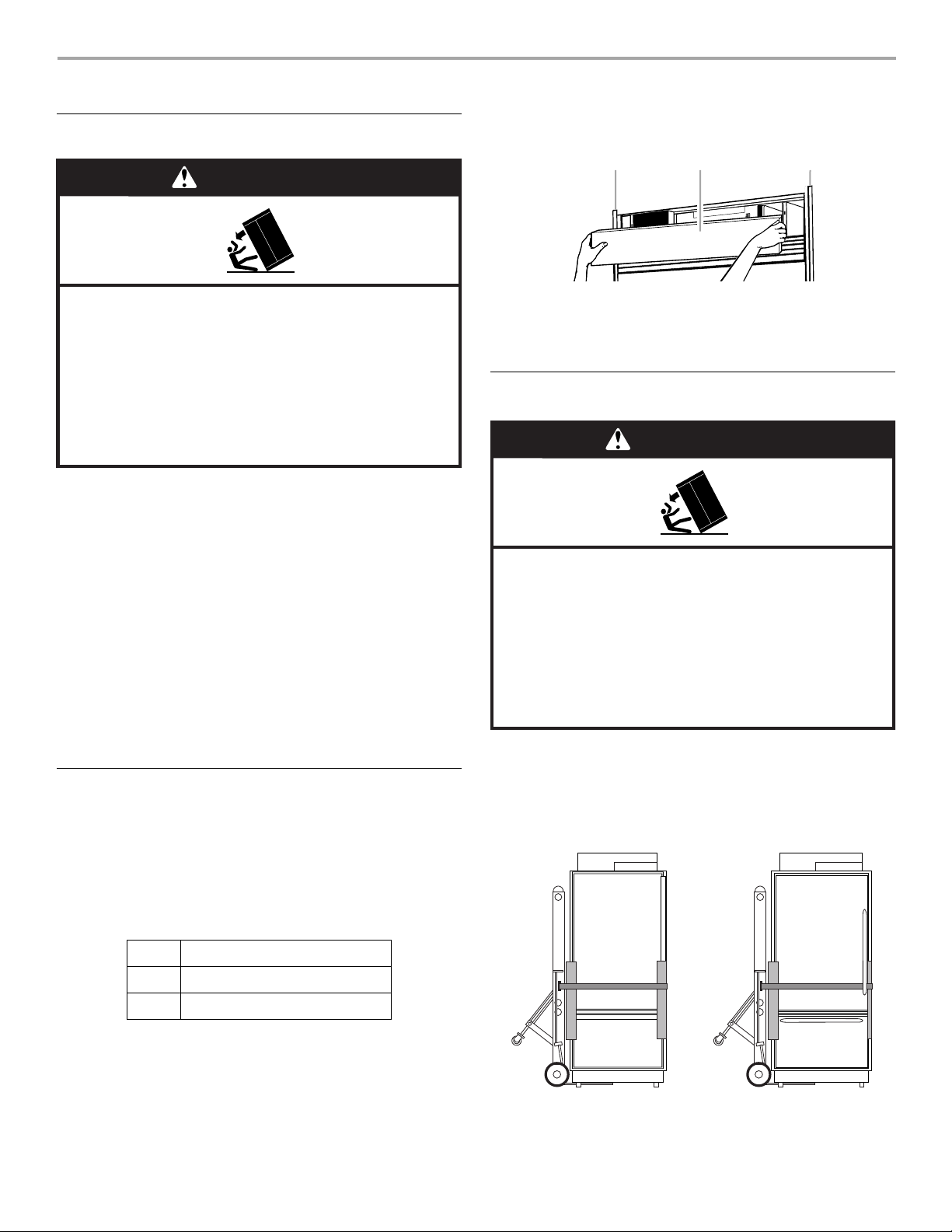
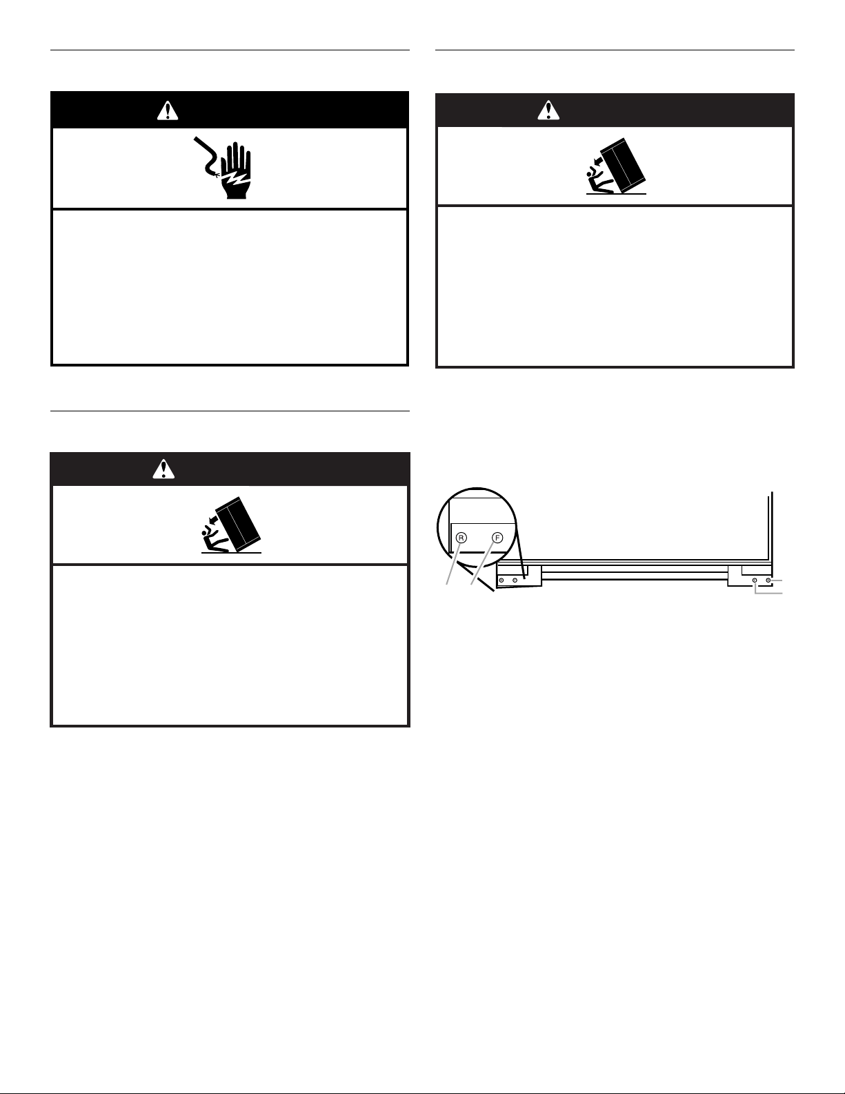
Tip Over Hazard
Refrigerator is top heavy and tips easily when not
completely installed.
Keep doors taped closed until refrigerator is
completely installed.
Use two or more people to move and install
refrigerator.
Failure to do so can result in death or serious injury.
3
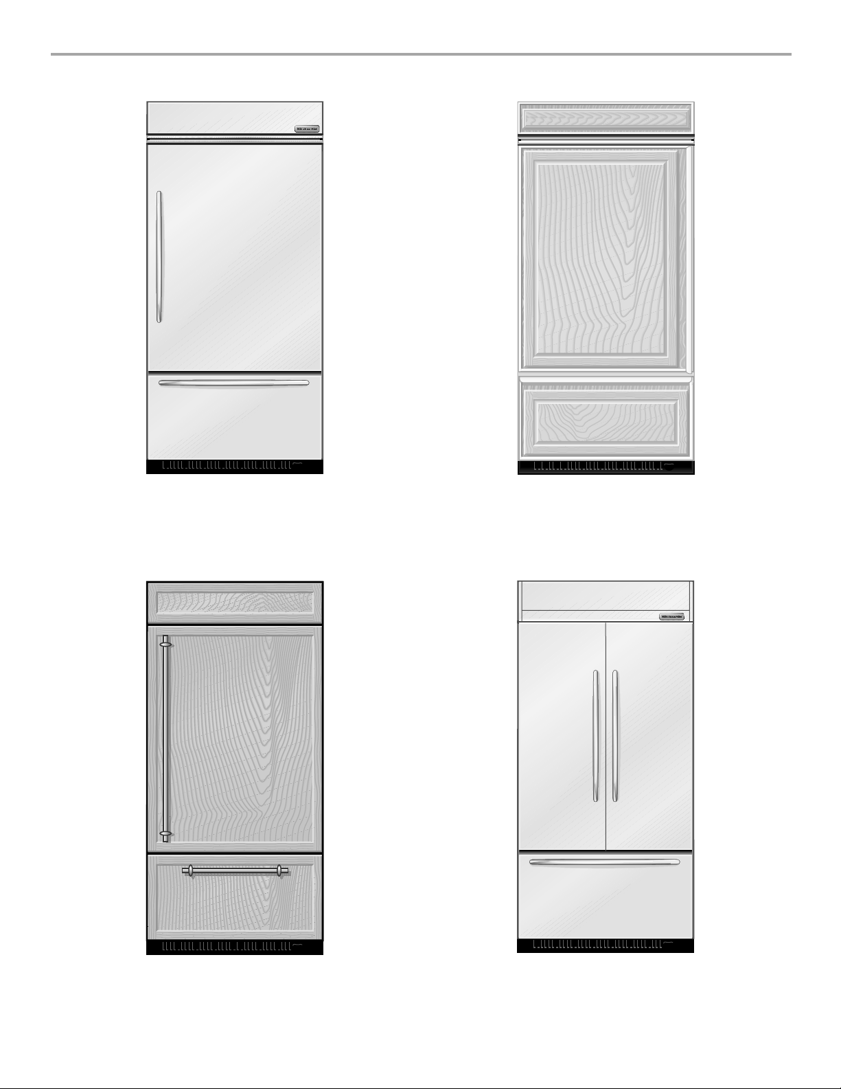
MODELS
Architect® Series (36" [91.4 cm] Models)
Features wraparound styling that complements the contoured
door handles. This series provides a warm commercial-looking
built-in refrigerator.
KBRC36FTS KBLC36FTS
Classic Series (36" [91.4 cm] Models)
Features traditional style trim, factory-installed, to provide a
“framed” look. This series requires the installation of custom panels
that are not included.
KBRS36FTB KBRS36FTX KBLS36FTB
KBLS36FTX
Overlay Series (36" [91.4 cm] Models)
Features factory-installed, overlay style trim, to provide a
“frameless” look. This series requires the installation of custom
panels, handles, and standoffs.
KBRO36FTX KBLO36FTX
4
®
Architect
Features wraparound styling that complements the contoured door
handles. This series provides a warm commercial-looking built-in
refrigerator.
KBFC42FTS
Series (42" [106.7 cm] Models)
Overlay Series (42" [106.7 cm] Models)
Features factory-installed, overlay style trim, to provide a
“frameless” look. This series requires the installation of custom
panels, handles, and standoffs.
KBFO42FTX
INSTALLATION
REQUIREMENTS
Tool s a nd Par ts
IMPORTANT:
■ Installer: Leave Installation Instructions with the homeowner.
■ Homeowner: Keep Installation Instructions for future
reference. Save these Installation Instructions for the local
electrical inspector’s use.
TOOLS NEEDED:
Gather the required tools and parts before starting installation.
Read and follow the instructions provided with any tools listed
here.
■ Cordless drill ■ To r x
■ Drill bits ■ ¹¹⁄₃₂" Nut driver
■ Two ad j u st ab le
■ ³⁄₈", ¹⁄₄", and ¹⁄₂" Open-end
wrenches
■ Phillips screwdriver ■ ⁵⁄₃₂" Hex key
■ Small level ■ ¹⁄₄" and ⁵⁄₁₆" Socket drivers
■ Appliance dolly ■ Tape measure
■ Utility knife
®†
T15 and T27 screwdrivers
wrenches
PARTS NEEDED:
■ Six #8 x 3" (7.6 cm) wood screws (longer screws may be needed)
■ One or two 2" x 4" x 32" (5 cm x 10 cm x 81 cm) wood board(s)
■ Order factory panels, make custom panels or consult a
qualified cabinetmaker or carpenter to make the panels.
Classic Series: Order factory panels, make custom panels, or
consult a qualified cabinetmaker or carpenter to make the
panels. See “Installation Requirements” for more information.
Overlay Series: Make custom panels, or consult a qualified
cabinetmaker or carpenter to make the panels. See
“Installation Requirements” for more information.
®
Architect
■ If you are connecting the water line directly to copper tubing
Series is shipped complete.
and not to a shutoff valve, you need a ferrule, a union, and a
¹⁄₄" compression fitting.
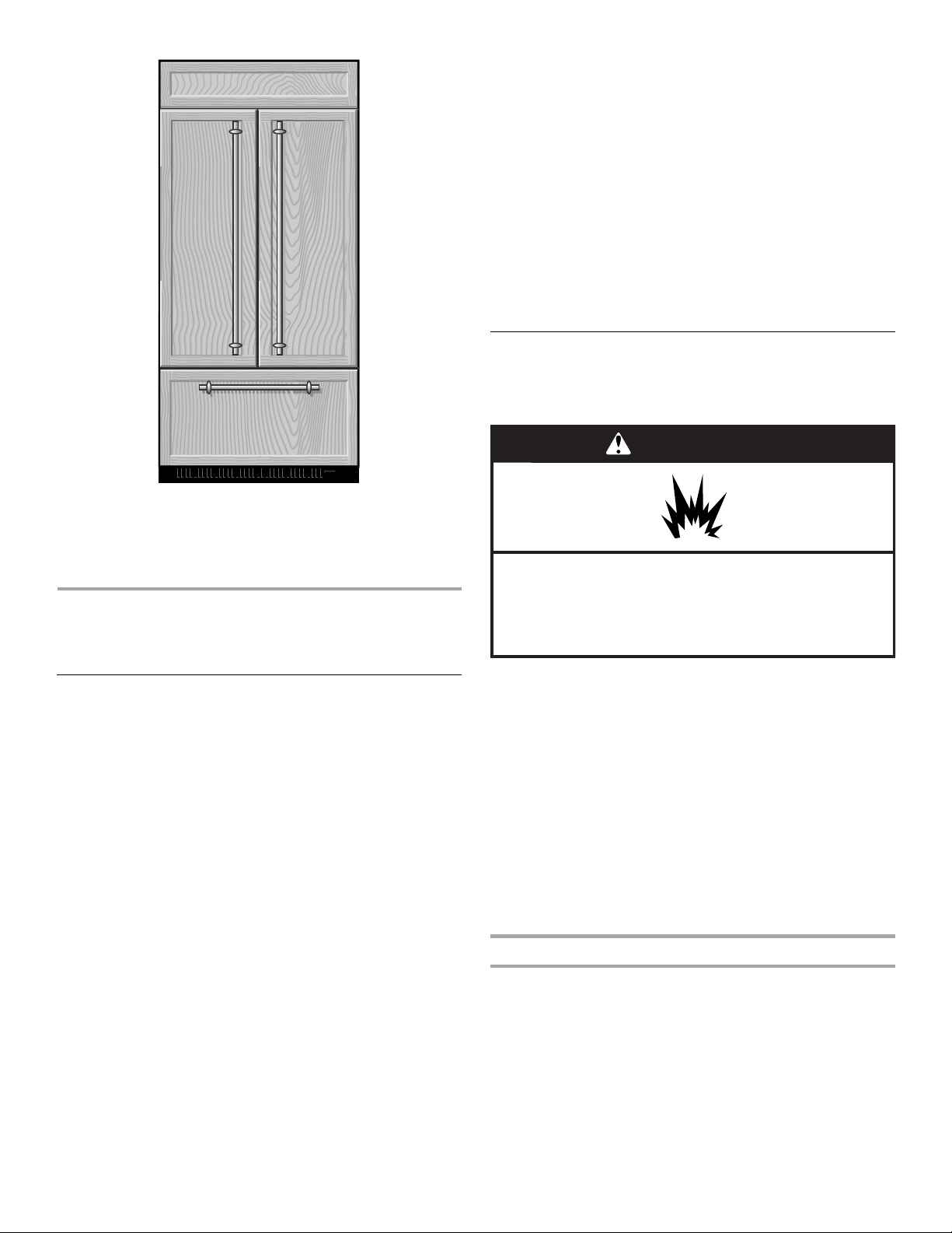
Location Requirements
The refrigerator can be recessed in an opening between cabinets
or installed at the end of a cabinet run using a side panel to
enclose the refrigerator.
WARNING
Explosion Hazard
Keep flammable materials and vapors, such as
gasoline, away from refrigerator.
Failure to do so can result in death, explosion, or fire.
IMPORTANT:
■ Observe all governing codes and ordinances.
■ It is recommended that you do not install the refrigerator near
an oven, radiator, or other heat source.
■ Do not install in a location where the temperature will fall
below 55°F (13°C).
■ Floor must support the refrigerator weight, more than 600 lbs
(272 kg), door panels and contents of the refrigerator.
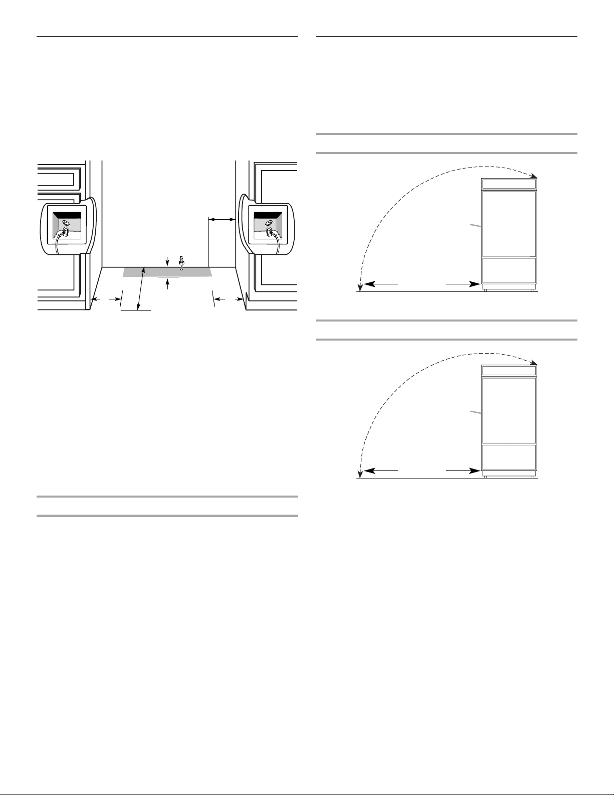
■ Ceiling height must allow for side tipping radius. See “Tipping
Radius.”
■ Location should permit door to open fully. See “Door Swing
Dimensions.”
■ Location must permit top grille removal. See “Opening
Dimensions.”
Opening Dimensions
■ To avoid tipping during use, the solid soffit must be within 1"
(2.5 cm) maximum above the refrigerator. If the solid soffit is
higher than 1" (2.5 cm) or one is not available, then the
refrigerator must be braced.
If the anti-tip boards are needed, they must be attached to the
rear wall studs 80" to 90" (203 to 229 cm) above the floor. See
“Install Anti-Tip Boards” for more information.
†®TORX is a registered trademark of Saturn Fasteners, Inc.
5
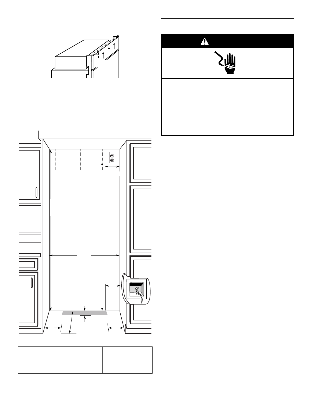
NOTE: A clearance of ¹⁄₂" (1.3 cm) must be maintained in front
of the refrigerator’s side trim in order for the top grille to be
removed.
¹⁄₂"
(1.3 cm)
Electrical Requirements
WARNING
■ A grounded 3 prong electrical outlet should be placed within
4" (10.2 cm) of the right side cabinets or end panel. See
“Electrical Requirements” for additional information.
■ The water shutoff should be located in the base cabinet on
either side of the refrigerator or some other easily accessible
area. If the water shutoff valve is not in the cabinets, the
plumbing for the water line can come through the floor or the
back wall. See “Water Supply Requirements” for more specific
information.
80" - 90"
(203-229 cm)
83¹⁄₂" (212.1 cm) min.
³⁄₄" (215 cm) max.
84
to bottom of solid soffit
B
Dimension
77"
(196 cm)
Electrical Shock Hazard
Plug into a grounded 3 prong outlet.
Do not remove ground prong.
Do not use an adapter.
Do not use an extension cord.
Failure to follow these instructions can result in death,
fire, or electrical shock.
Before you move your refrigerator into its final location, it is
important to make sure you have the proper electrical connection.
Recommended Grounding Method
A 115 volt, 60 Hz., AC only, 15- or 20-amp fused, grounded
electrical supply is required. It is recommended that a separate
circuit serving only your refrigerator be provided. Use an outlet
that cannot be turned off by a switch. Do not use an
extension cord.
IMPORTANT: If this product is connected to a GFCI (Ground Fault
Circuit Interrupter) protected outlet, nuisance tripping of the
power supply may occur, resulting in loss of cooling. Food quality
and flavor may be affected. If nuisance tripping has occurred, and
if the condition of the food appears poor, dispose of it.
NOTE: Before performing any type of installation, cleaning, or
removing a light bulb, remove the top grille and turn the master
power switch to OFF or disconnect power at the circuit breaker
box.
When you are finished, turn ON the master power switch or
reconnect power at the circuit breaker box. Then reset the control
to the desired setting.
A
Width
(see chart following)
6"
(15.2 cm)
1"
24"
(2.54 cm)
6"
(15.2 cm)
6"
(15.2 cm)
(60.96 cm) min.
Model Width A (as shown above) Dimension B
(as shown above)
36
42
35¹⁄₂" (90.2 cm)
41¹⁄₂" (105.4 cm)
4" (10.2 cm)
10" (25.4 cm)
NOTE: Flooring under refrigerator must be at same level as the
room.
6
Water Supply Requirements
■ All installations must meet local plumbing code requirements.
■ The water shutoff should be located in the base cabinet on
either side of the refrigerator or some other easily accessible
area. The right-hand side is recommended. The access hole
through the cabinet must be within ¹⁄₂" (12.7 mm) of the rear
wall.
NOTE: If the water shutoff valve is in the back wall behind the
refrigerator, it must be at an angle so that the tube is not
kinked when the refrigerator is pushed into its final location.
6"
(15.2 cm)
6"
(15.2 cm)
■ If the water shutoff valve is not in the cabinets, the plumbing
24"
(60.96 cm) min.
for the water line can come through the floor. A ¹⁄₂" (12.7 mm)
hole for plumbing should be drilled at least 6" (15.2 cm) from
the right or left hand side cabinet or panel. On the floor, the
hole should be no more than 1" (2.54 cm) away from the back
wall. See “Connect the Water Supply.”
■ If additional tubing is needed, use copper tubing and check
for leaks. Install the copper tubing only in areas where the
household temperatures will remain above freezing.
■ Do not use a piercing-type or ³⁄₁₆" (4.76 mm) saddle valve
which reduces water flow and clogs more easily.
NOTE: Your refrigerator dealer has a kit available with a ¹⁄₄"
(6.35 mm) saddle-type shutoff valve, a union, and copper
tubing. Before purchasing, make sure a saddle-type valve
complies with your local plumbing codes.
Water Pressure
1"
(2.54 cm)
6"
(15.2 cm)
Tipping Radius
Be sure there is adequate ceiling height to stand the refrigerator
upright when it is moved into place.
■ The dolly wheel height must be added to the tipping radius
when a dolly is used.
■ If needed, the tipping radius can be reduced. See “Reduce
Tipping Radius.”
Side Tipping Radius (36" [91.4 cm] Models)
A
90¹⁄₂"
(229.9 cm)
A. Tip this side only.
Side Tipping Radius (42" [106.7 cm] Models)
A
93"
(236.2 cm)
A. Tip this side only.
A cold water supply with water pressure between 30 and 120 psi
(207 and 827 kPa) is required to operate the water dispenser and
ice maker. If you have questions about your water pressure, call a
licensed, qualified plumber.
Reverse Osmosis Water Supply
IMPORTANT: The pressure of the water supply coming out of a
reverse osmosis system going to the water inlet valve of the
refrigerator needs to be between 30 and 120 psi
(207 and 827 kPa).
If a reverse osmosis water filtration system is connected to your
cold water supply, the water pressure to the reverse osmosis
system needs to be a minimum of 40 to 60 psi (276 to 414 kPa).
If the water pressure to the reverse osmosis system is less than
40 to 60 psi (276 to 414 kPa):
■ Check to see whether the sediment filter in the reverse
osmosis system is blocked. Replace the filter if necessary.
■ Allow the storage tank on the reverse osmosis system to refill
after heavy usage.
■ If your refrigerator has a water filter cartridge, it may further
reduce the water pressure when used in conjunction with a
reverse osmosis system. Remove the water filter cartridge.
If you have questions about your water pressure, call a licensed,
qualified plumber.
7
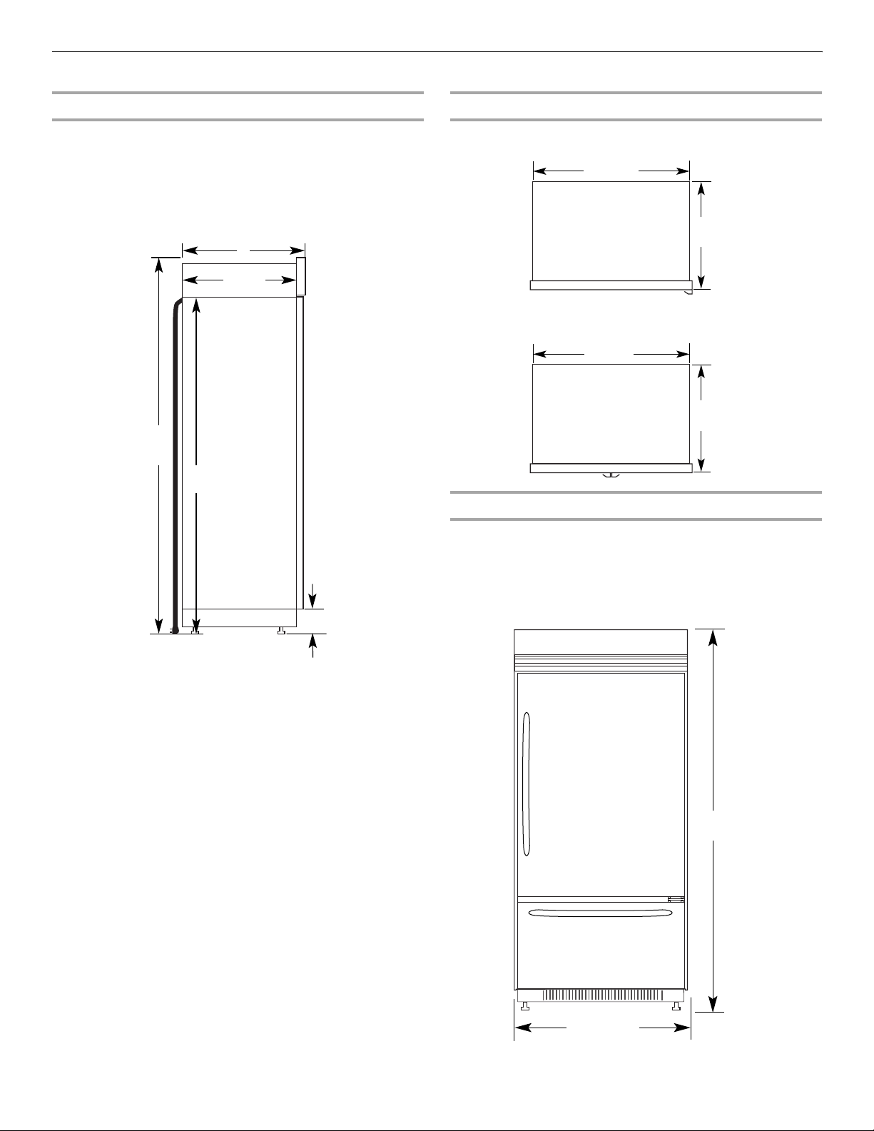
Product Dimensions
Side View
■ The depth from the front of the top grille to the back of the
refrigerator cabinet is 25³⁄₈" (64.5 cm).
■ The power cord is 84" (213 cm) long.
■ The water line attached to the back of the refrigerator is 5 ft
(1.5 m) long. Height dimensions are shown with leveling legs
extended ¹⁄₈" (3 mm) below the rollers.
A
23¹⁄₂"
(59.7 cm)
*83³⁄₈"
(211.8 cm)
84" (213.4 cm)
Power Cord
Top Vi ew
36" (91.4 cm) Models
42" (106.7 cm) Models
Front View
35¹⁄₄"
(89.5 cm)
¹⁄₄"
41
(105 cm)
25³⁄₈"
(64.5 cm)
25³⁄₈"
(64.5 cm)
¹⁄₂" (8.9 cm)
*3
*When leveling legs are fully extended to 1¹⁄₄" (3.2 cm) below
rollers, add 1¹⁄₈" (2.9 cm) to the height dimensions.
■ Width dimensions were measured from trim edge to trim
edge.
■ Height dimensions are shown with leveling legs extended ¹⁄₈"
(3 mm) below the rollers.
36" (91.4 cm) Models
*83³⁄₈"
(211.8 cm)
36¹⁄₄" (92 cm)
*When leveling legs are fully extended to 1¹⁄₄" (3.2 cm) below
rollers, add 1¹⁄₈" (2.9 cm) to the height dimensions.
8
42" (106.7 cm) Models
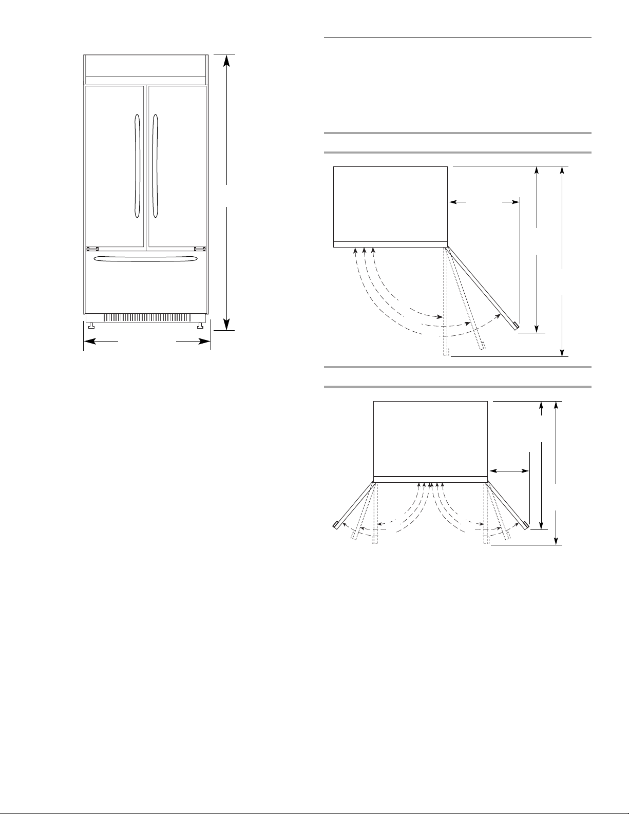
Door Swing Dimensions
The location must permit the door to open to a minimum of 90°.
Allow 4¹⁄₂" (11.4 cm) minimum space between the side of the
refrigerator and a corner wall.
NOTE: More clearance may be required if you are using overlay
panels or custom handles.
To adjust the door swing, see “Adjust Door Swing.”
36" (91.4 cm) Models
*83³⁄₈"
(211.8 cm)
42¹⁄₄" (107.3 cm)
*When leveling legs are fully extended to 1¹⁄₄" (3.2 cm) below
rollers, add 1¹⁄₈" (2.9 cm) to the height dimensions.
90˚
110˚
130˚
42" (106.7 cm) Models
23"
(58 cm)
max.
(102.7 cm)
13
¹⁄₂"
(34.3 cm)
max.
51"
(130 cm)
59"
(150 cm)
40⁷⁄₁₆"
110˚
130˚
90˚
44¹⁄₄"
(112.3 cm)
90˚
110˚
130˚
9
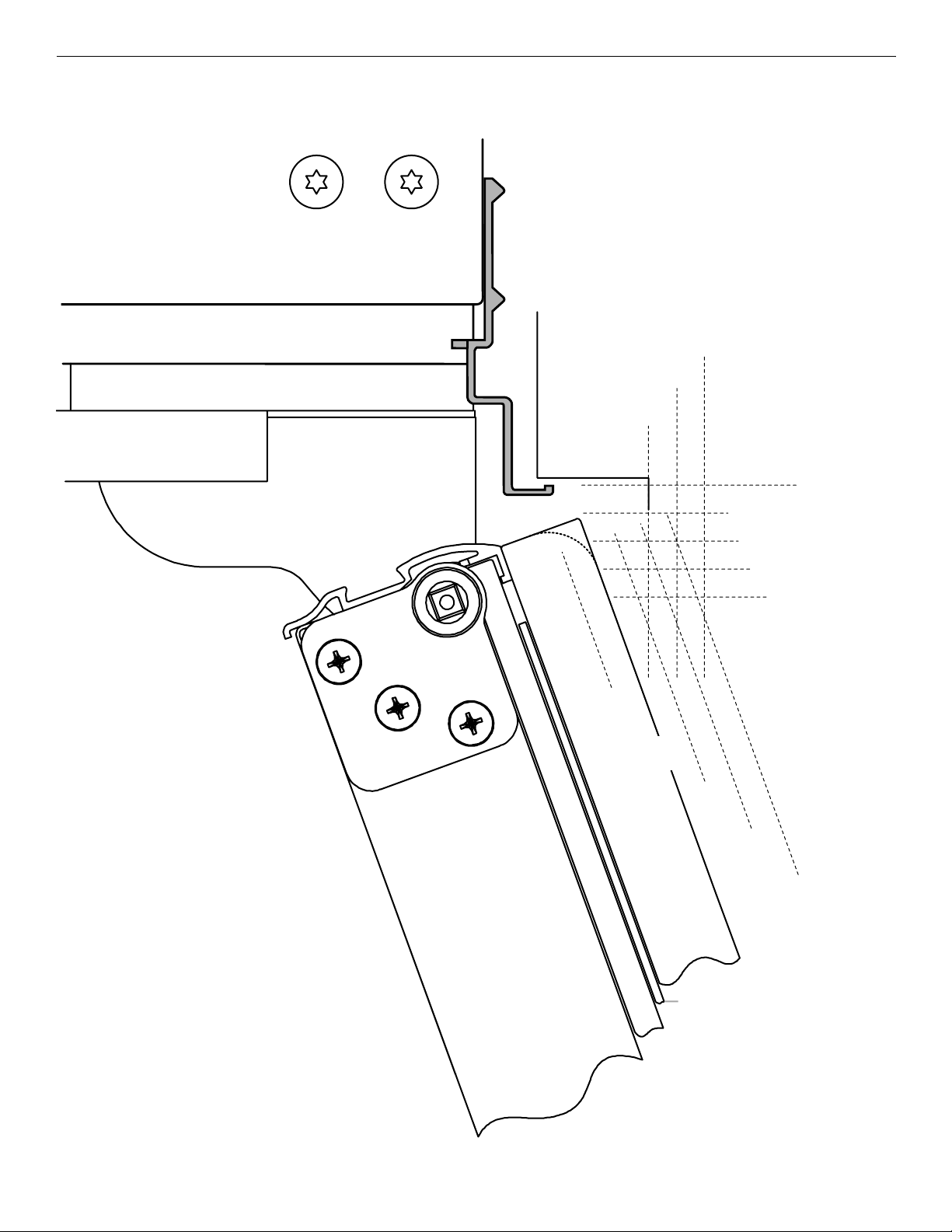
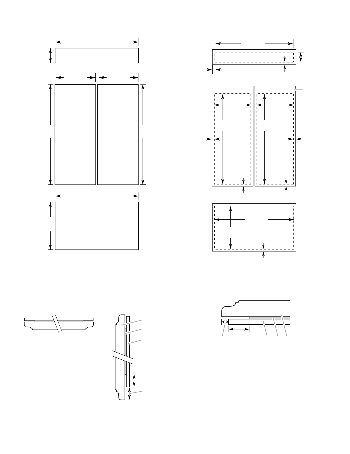
Overlay Series Door Panel and Cabinetry Clearance (36" [91.4 cm] Models)
The custom door panels and adjacent cabinetry must be designed so that there is sufficient clearance for the doors to swing open. If
the refrigerator is to be installed close to the wall, see “Door Swing 90°” on next page.
Door Swing 110˚
Actual Size
Refrigerator to
Cabinetry Clearance
Refrigerator
Side Trim
1
1
/2"
(3.8 cm)
1
1
/4"
(3.2 cm)
1"
(2.5 cm)
Cabinetry
1
/4" (6.35 mm)
Hinge
1
/2" (1.3 cm)
3
/4" (1.9 cm)
NOTE: For Overlay Series models, rout the
hinge side of the custom door panels to a
radius that is equal to at least half the
thickness of the panel if a 130˚ door swing is
desired. See “Adjust Doors.”
Door
1
/2"
(1.3 cm)
Backer Panel
3
/4"
(1.9 cm)
Overlay Panel
(2.5 cm)
Spacer Panel
1"
1" (2.5 cm)
NOTE: Allow ¹⁄₂"
(1.3 cm) clearance
between overlay
panel and cabinetry.
1
/4"
1
(3.2 cm)
1
/2"
1
(3.8 cm)
When the doors are closed the refrigerator will extend beyond the face of the adjacent cabinetry to some degree.
10
90˚ Door
Stop Position
Hinge
Door Swing 90˚
Actual Size
Refrigerator to
Cabinetry Clearance
Refrigerator
Side Trim
3
/4"
(1.9 cm)
1
/2"
(1.3 cm)
Cabinetry
1"
(2.5 cm)
1
/4" (6.35 mm)
1
/2" (1.3 cm)
3
/4" (1.9 cm)
1" (2.5 cm)
1
/2"
(1.3 cm)
3
/4"
(1.9 cm)
1"
(2.5 cm)
1
1
Door
Backer Panel
Overlay Panel
/4"
(3.2 cm)
1
/2"
1
(3.8 cm)
Spacer Panel
Allow a minimum of 4¹⁄₂" (11.4 cm) of space between the side of the refrigerator and a corner wall. More clearance may be needed if
thicker custom panels or custom handles are used. Do not overlook baseboards.
11
Overlay Series Door Panel and Cabinetry Clearance (42" [106.7 cm] Models)
The custom door panels and adjacent cabinetry must be designed so that there is sufficient clearance for the doors to swing open. If
the refrigerator is to be installed close to the wall, see “Door Swing 90°” on next page.
Door Swing 110˚
Actual Size
Refrigerator to
Cabinetry Clearance
Refrigerator
Side Trim
1
1
/2"
(3.8 cm)
1
1
/4"
(3.2 cm)
1"
(2.5 cm)
Cabinetry
1
/4" (6.35 mm)
Hinge
1
/2" (1.3 cm)
3
/4" (1.9 cm)
NOTE: For Overlay Series models, rout the
hinge side of the custom door panels to a
radius that is equal to at least half the
thickness of the panel if a 130˚ door swing is
desired. See “Adjust Doors.”
Door
1
/2"
(1.3 cm)
Backer Panel
3
/4"
(1.9 cm)
Overlay Panel
(2.5 cm)
Spacer Panel
1"
1" (2.5 cm)
NOTE: Allow ¹⁄₂"
(1.3 cm) clearance
between overlay
panel and cabinetry.
1
/4"
1
(3.2 cm)
1
/2"
1
(3.8 cm)
When the doors are closed the refrigerator will extend beyond the face of the adjacent cabinetry to some degree.
12
90˚ Door
Stop Position
Hinge
Door Swing 90˚
Actual Size
Refrigerator to
Cabinetry Clearance
Refrigerator
Side Trim
3
/4"
(1.9 cm)
1
/2"
(1.3 cm)
Cabinetry
1"
(2.5 cm)
1
/4" (6.35 mm)
1
/2" (1.3 cm)
3
/4" (1.9 cm)
1" (2.5 cm)
1
/2"
(1.3 cm)
3
/4"
(1.9 cm)
1"
(2.5 cm)
1
1
Door
Backer Panel
Overlay Panel
/4"
(3.2 cm)
1
/2"
1
(3.8 cm)
Spacer Panel
Allow a minimum of 4¹⁄₂" (11.4 cm) of space between the side of the refrigerator and a corner wall. More clearance may be needed if
thicker custom panels or custom handles are used. Do not overlook baseboards.
13
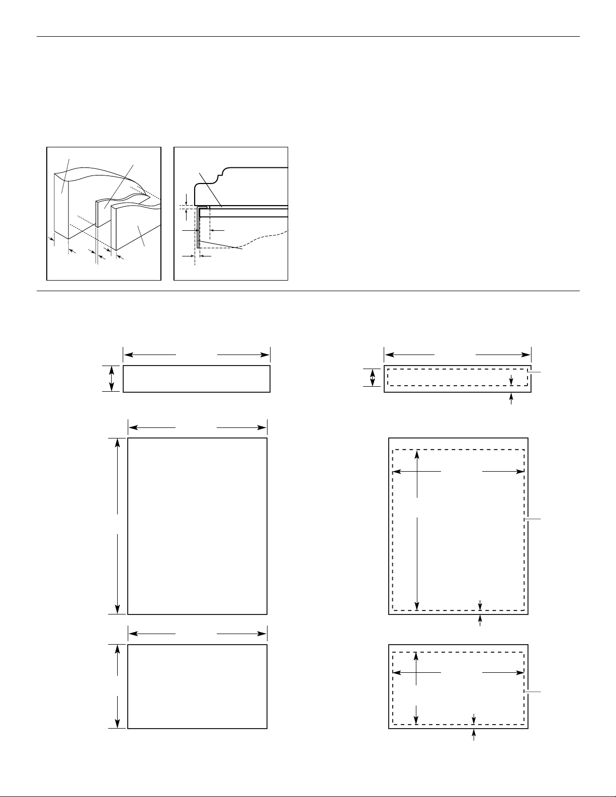
Overlay Series Custom Panels
Custom overlay panels allow you to blend the exterior of your
refrigerator into the overall kitchen décor and to use custom
handles for additional design flexibility.
The custom panels must have backer panels attached in order to
mount them to the refrigerator. It is most common to work with
three panels, as shown in the following graphic: a decorative
overlay panel, a ¹/₈" (3.18 mm) spacer panel or spacer strips and a
¹/₄" (6.35 mm) backer panel.
Overlay Panel
5
/8" to 3/4"
(15.88 to
19.05 mm)
(3.18 mm)
1
/8"
Spacer Panel
Backer Panel
1
/4"
(6.35 mm)
Spacer Panel
1
/8"
(3.18 mm)
Overlay Panel
Backer Panel
1" minimum
(2.54 cm)
Offset Dimension
Door/Grille Trim
Custom Overlay Panel Dimensions
Custom Overlay Panels (36" [91.4 cm] Models) Custom Backer Panels (36" [91.4 cm] Models)
In some cases, your cabinet manufacturer may choose to work
with one panel routed for the different dimensions. Follow these
panel dimension and placement instructions to be sure that the
custom overlay panels will fit properly.
IMPORTANT:
■ For 36" (91.4 cm) models, the refrigerator door overlay panel
cannot exceed 50 lbs (23 kg) and the freezer drawer overlay
panel cannot exceed 20 lbs (9.1 kg).
■ For 42" (106.7 cm) models, the refrigerator door overlay panel
cannot exceed 30 lbs (13.5 kg) and the freezer drawer overlay
panel cannot exceed 25 lbs (11.4 kg).
■ The weight of the top grille overlay panel cannot exceed
10 lbs (4.5 kg) for both models.
To minimize panel weight, you may use 2" (5.08 cm) spacer strips
around the perimeter in place of full-sheet solid spacer panels.
The spacer strips must be set in at least 1" (2.54 cm) from the top,
bottom and side edges of the backer panel. If you use spacer
strips, it is also recommended that you use two 2" (5.08 cm) strips
horizontally centered for added support.
7¹⁄₄"
(18.42 cm)
(129.86 cm)
51¹⁄₈"
34³⁄₄"
(88.27 cm)
TOP GRILLE PANEL
Maximum Weight: 10 lbs (4.5 kg)
34³⁄₄"
(88.27 cm)
REFRIGERATOR DOOR PANEL
Maximum Weight: 50 lbs (23 kg)
34³⁄₄"
(88.27 cm)
6³⁄₁₆"
(15.72 cm)
49¹⁄₈"
(124.78 cm)
33³⁄₄"
(85.73 cm)
34¹⁄₄"
(87.00 cm)
Center
Backer
Panel
left to
right
Bottom Offset
³⁄₈" (9.5 mm)
Center
Backer
Panel
left to
right
Bottom Offset
⁷⁄₁₆" (11.1 mm)
14
20³⁄₄"
(52.71 cm)
FREEZER DOOR PANEL
Maximum Weight: 20 lbs (9.1 kg)
20³⁄₁₆"
(51.28 cm)
34¹⁄₄"
(87.00 cm)
Center
Backer
Panel
left to
right
Bottom Offset
¹⁄₄" (6.35 mm)
Custom Overlay Panels (42" [106.7 cm] Models) Custom Backer Panels (42" [106.7 cm] Models)
40
⁷⁄₁₆
7
¹⁄₄
(18.4 cm)
51
(130.2 cm)
"
REFRIGERATOR
¹⁄₄
"
DOOR PANEL
Maximum Weight:
30 lbs (13.5 kg)
"
(102.7 cm)
TOP GRILLE PANEL
Maximum Weight: 10 lbs (4.5 kg)
20"
(50.8 cm)
20"
(50.8 cm)
REFRIGERATOR
DOOR PANEL
Maximum Weight:
30 lbs (13.5 kg)
51
¹⁄₄
"
(130.2 cm)
Side
Offset
3
/
16"
(4.7 mm)
Side Offset
3
/
8" (9.5 mm)
(49.85 cm)
493/
16"
(124.93 cm)
(1.27 cm)
195/
8"
Bottom
Offset
395/
8"
(100.6 cm)
1
/
2"
195/
8"
(49.85 cm)
493/
16"
(124.93 cm)
Bottom
Offset
(1.27 cm)
Bottom Offset
1
1
/
2"
61/
(15.9 cm)
/
2" (1.27 cm)
Exterior
Panel
extends
above
door.
Side
Offset
3
/
16"
(4.7 mm)
4"
40
⁷⁄₁₆
"
(102.7 cm)
20
¹⁄₄
(51.4 cm)
"
FREEZER DOOR PANEL
Maximum Weight: 25 lbs (11.4 kg)
197/
8"
40"
(101.6 cm)
(50.48 cm)
Offset all sides
3
/
16" (4.7 mm)
Spacer Panels (All models)
NOTE: Spacer panels must be at least 1" (2.54 cm) from the top, bottom, and side edges of the backer panel.
3-Piece Grille Overlay Panel Configuration 3-Piece Door Overlay Panel Configuration
Top View Side View
D
A. Offset dimension
B.
¹₄
" (6.25 mm) Backer panel
¹₈
" (3.18 mm) Spacer panel
C.
³₄
" (1.92 cm) Decorative
D.
overlay panel
C
B
A. Offset dimension
B.
C.
D.
1"
(2.54 cm)
¹₄
" (6.25 mm) Backer panel
¹₈
" (3.18 mm) Spacer panel
³₄
" (1.92 cm) Decorative overlay panel
B
DA C
1"
(2.54 cm)
A
1-Piece Overlay Panel Configuration
In some cases, your cabinet manufacturer may choose to work
with one panel routed for the different dimensions. Follow these
panel dimesions and placement instructions to be sure that the
custom overlay panels will fit properly.
15
Classic, Architect®, and Overlay Series
Factory Panels and Kits
(36" [91.4 cm] Models)
All factory parts are available through your KitchenAid dealer or by
calling KitchenAid Parts and Accessories at 1-800-442-9991. In
Canada, call 1-800-807-6777.
Architect® Series 72" (183 cm) Top Grille Panel Kit
A 72" (183 cm) wide Top Grille Panel Kit is available. This kit allows
2 units (one left-hand swing and one right-hand) to be installed
side by side with a single grille.
Color 72" (183 cm)
®
Stainless Steel (Architect
Extended Door Handle Kits
Use extended door handles when additional finger clearance is
needed between the door handles and custom panel. Follow the
kit instructions for installing the door handles.
Color Left-Hand Swing Right-Hand
White (Classic
Series)
Black (Classic
Series)
Stainless Steel
(Classic Series)
Matte Aluminum
Etched (Classic
Series)
Matte Aluminum
(Overlay Series)
Series) #W10153554
Swing
#4396119 #8171424
#4396116 #8171427
#4396118 #8171425
#4396120 #8171423
#4396718
Refrigerator and Freezer Panels
The freezer panel should not weigh more than 20 lbs (9.1 kg). The
refrigerator panel should not weigh more than 50 lbs (22 kg).
34¹⁄₄"
(87 cm)
49"
(124.5 cm)
34¹⁄₄"
(87 cm)
20¹⁄₈"
(51.1 cm)
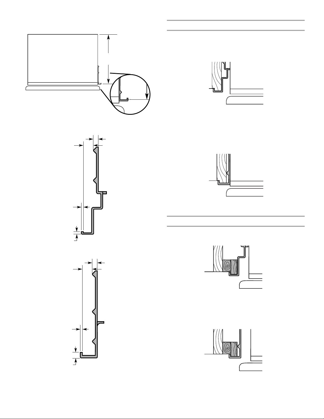
Top Grille Panel – Routing Requirements
If the custom panels are thicker than ¹⁄₄" (6.35mm), the top and
bottom edges of the top panel should be edge routed ¹⁄₂"
(1.27 cm) and ³⁄₈" (9.5 mm), respectively. Both ends should be
edge routed ⁷⁄₈" (2.2 cm) as shown.
Classic Series Custom Panels
(36" [91.4 cm] Models)
If you plan to install custom wood panels, you will need to create
the panels yourself or consult a qualified cabinetmaker or
carpenter. See dimension drawings for panel specifications.
IMPORTANT: Panels weighing more than recommended may
cause damage to your refrigerator.
NOTE: Dimensions shown have a (±)¹⁄₁₆" (1.5 mm) tolerance.
Panels that are more than ¹⁄₄" (6.35 mm) thick must be routed. If
panels are less than ¹⁄₄" (6.35 mm) thick, install a filler panel
between the door and the decorative panel.
Top Grille Panel
The top panel should not weigh more than 10 lbs (4.5 kg).
34¹⁄₂"
(87.63 cm)
7¹⁄₄"
(18.4 cm)
¹⁄₄"
(6.35 mm)
max.
⁷⁄₈"
(2.2 cm)
Top
Grille
Top
Grille
⁷⁄₈"
(2.2 cm)
¹⁄₄
"
(6.35 mm)
max.
16
NOTE: When creating a panel with face detail, the offsets will be
¹⁄₂" (1.3 cm)
min.
¹⁄₄"
(6.35 mm)
max.
hidden and must be accounted for in order to center the detail in
the top grille.
¹⁄₄"
(6.35 mm) max.
Door Panel - Side View
¹⁄₂"
(1.3 cm)
min.
Center face
detail between
offsets
³⁄₈"
(9.5 mm)
min.
Top
Bottom
¹⁄₄"
(6.35 mm) max.
Door Panel – Routing Requirements
If the custom panels are thicker than ¹⁄₄" (6.35 mm), then all edges
of the panels must be routed. If the standard handle is used, rout
the entire handle side of both panels 3¹⁄₄" (8.25 cm) to allow for
finger clearance. Then rout the hinge side of the refrigerator panel
1" (2.54 cm). Rout both sides of the freezer panel 1" (2.54 cm).
Standard Handle – Top View
3¹⁄₄"
(8.25 cm)
min.
Hinge Side
Panel
Extended Handle - Top View
1"
¹⁄₄"
(6.35 mm)
Door
Panel
Handle
(2.54 cm)
max
Hinge Side
Door
Panel
1"
(2.54 cm)
Classic and Architect® Series
Custom Side Panels
Custom side panels may be needed when not enough space is
available to have cabinets on both sides of the refrigerator or
when the refrigerator is placed and the end of a cabinet run. You
may choose an Inset, Flush, or Recessed Inset panel installation.
¹⁄₄" (6.35 mm) max.
Handle
Door
Panel
2" (5 cm)
min.
Door
Panel
If an extended handle kit is used, rout the handle side ¹⁄₄"
(6.35 mm). All other routing dimensions would remain the same as
the standard handle. Make sure your product location will allow
doors with extended handles to be opened to 90 degrees. See
“Door Swing Dimensions.”
For more information on ordering extended handles, see “Classic
Series Factory Panels and Kits.”
NOTE: For both types of handles, rout the top and bottom edges
of the refrigerator panel ¹⁄₂" (1.27 cm). Rout the bottom of the
freezer panel ¹⁄₂" (1.27 cm).
1"
(2.54 cm)
Refrigerator and Side Trim Dimensions
The width and height of a side panel are determined by the type of
installation you are planning.
NOTES:
■ The dimensions shown are actual product dimensions and
may not reflect the needed panel installation dimensions.
■ The side panel should be a minimum of ¹⁄₂" (1.27 cm) thick
to avoid warping.
■ If the opening depth is 25" (63.5 cm) or more, you may
want to install a support board on the rear wall.
Refrigerator
24¹⁄₈"
(61.3 cm)
23¹¹⁄₁₆"
(60.3 cm)
¹⁄₂"
23
(59.7 cm)
17
Side Trim
(6.35 mm)
³⁄₁₆"
(4.7 mm)
⁷⁄₃₂"
(5.5 mm)
¹⁄₄"
Recessed Inset Installation Dimensions
1. Measure the distance from point A (as shown) to back wall.
¹¹⁄₆₄"
(4.5 mm)
A
2. Rout the front edge of the support board or attach a ¹⁄₄"
(6.35 mm) board to hold the panel in the cabinet side trim.
¹³⁄₃₂" (10 mm)
⁵⁄₈"
(15.7 mm)
Inset Installation Dimensions
1. Measure the distance from point A (as shown) to the back
wall. Add ⁷⁄₃₂" (5.6 mm) to this measurement to allow the side
panel to fit into the trim.
A
2. If the panel is more than ¹⁄₄" (6.35 mm) thick, rout the front
edge to allow the side panel to fit into the trim.
Flush Installation Dimensions
1. Measure the distance from point A (as shown) to the back
wall.
Overlay Series Custom Side Panels
Custom side panels may be needed when not enough space is
available to have cabinets on both sides of the refrigerator or
when the refrigerator is placed and the end of a cabinet run. You
may choose an Inset or Recessed Inset panel installation.
Refrigerator and Side Trim Dimensions
The width and height of a side panel are determined by the type of
installation you are planning.
NOTES:
■ The dimensions shown are actual product dimensions and
may not reflect the needed installation dimensions.
■ The side panel should be a minimum of ¹⁄₂" (1.27 cm) thick
to avoid warping.
■ If the opening depth is 25" (63.5 cm) or more, you may
want to install a support board on the rear wall.
Refrigerator (36" [91.4 cm] Models)
Overlay
23¹¹⁄₁₆"
(60.16 cm)
A
2. Attach the support board with a screw or adhesive that is
compatible with aluminum and wood.
18
Refrigerator (42" [106.7 cm] Models)
Overlay
(59.40 cm)
Inset Installation Dimensions
36" [91.4 cm] Models
1. Measure the distance from point A (as shown) to the back
wall. Add ¹⁄₃₂" (0.8 mm) to this measurement to allow the side
panel to fit into the trim.
23³⁄₈"
A
2. If the panel is more than ³⁄₈" (9.5 mm) thick, rout the front edge
to allow the side panel to fit into the trim
Side Trim (36" [91.4 cm] Models)
³⁄₈"
(9.7 mm)
¹⁄₁₆"
(1.5 mm)
³⁄₃₂"
(2.38 mm)
Side Trim (42" [106.7 cm] Models)
³⁄₈"
(9.7 mm)
³⁄₁₆"
(4.5 mm)
³⁄₁₆"
(4.5 mm)
42" [106.7 cm] Models
1. Measure the distance from point A (as shown) to the back
wall. Add ¹⁄₃₂" (0.8 mm) to this measurement to allow the side
panel to fit into the trim.
A
2. If the panel is more than ³⁄₈" (9.5 mm) thick, rout the front edge
to allow the side panel to fit into the trim
Recessed Inset Installation Dimensions
36" [91.4 cm] Models
1. Measure the distance from point A (as shown) to back wall.
A
¹⁄₁₆"
(1.5 mm)
¹⁄₈"
(3.2 mm)
2. Rout the front edge of the support board or attach a ³⁄₈"
(9.5 mm) board to hold the panel in the cabinet side trim.
42" [106.7 cm] Models
1. Measure the distance from point A (as shown) to back wall.
A
2. Rout the front edge of the support board or attach a ³⁄₈"
(9.5 mm) board to hold the panel in the cabinet side trim.
19
INSTALLATION INSTRUCTIONS
Unpack the Refrigerator
WARNING
2. Push the top grille straight up; then pull straight out. Lay the
grille on a soft surface.
B BA
Tip Over Hazard
Refrigerator is top heavy and tips easily when not
completely installed.
Keep doors taped closed until refrigerator is
completely installed.
Use two or more people to move and install
refrigerator.
Failure to do so can result in death or serious injury.
IMPORTANT:
■ Do not remove the film covering until the refrigerator is in its
operating location.
■ All four leveling legs must contact the floor to support and
stabilize the full weight of the refrigerator.
■ Keep the cardboard shipping piece or plywood under the
refrigerator until it is installed in the operating location.
1. Remove and save the literature package bag taped to the side
of the refrigerator and the parts bag behind the grille. Remove
the four brackets (two on each side) that attach the shipping
base to the refrigerator bottom.
NOTE: Do not remove tape and door bracing until the
refrigerator is in its final location.
2. If necessary, reduce the tipping radius. See “Tipping Radius”
for ceiling height requirements or “Reduce Tipping Radius” for
step-by-step instructions. If you do not need to reduce the
tipping radius, proceed to “Move the Refrigerator into House.”
Reduce Tipping Radius
(if required)
Before bringing the refrigerator into the home, be sure there is
adequate ceiling height to stand the refrigerator upright. See
“Tipping Radius” in the “Installation Requirements” section for
more information.
If you do not have adequate ceiling height to stand the refrigerator
upright, the tipping radius can be reduced by removing the top
grille and side trims (see the following chart).
Model Reduced Tipping Radius
A. Top grille
B. Cabinet side trim
3. Remove the six screws attaching each cabinet side trim to the
refrigerator and remove the side trims.
Move the Refrigerator into House
WARNING
Tip Over Hazard
Refrigerator is top heavy and tips easily when not
completely installed.
Keep doors taped closed until refrigerator is
completely installed.
Use two or more people to move and install
refrigerator.
Failure to do so can result in death or serious injury.
1. Place an appliance dolly under the left side of the refrigerator
as shown. Place the corner posts from the packing materials
over the trims and handles as appropriate to avoid damage.
Slowly tighten the strap.
NOTE: Pass the dolly strap under the handles.
36" (91.4 cm) Models
36 88" (223.5 cm)
42 88¹⁄₂" (224.8 cm)
1. Grasp both ends of the top grille.
20
42" (106.7 cm) Models
C
A
B
C
2. Place pieces of the shipping carton on the floor when rolling
the dolly and refrigerator into the house. Move the refrigerator
close to the built-in opening.
3. Place top of cardboard carton or plywood under refrigerator.
4. Stand the refrigerator up. First, place the left bottom edge of
the refrigerator on the floor, stand the refrigerator upright and
then lower the right-hand side of the refrigerator to the floor.
5. Do not remove film or cover.
6. Reassemble the trim and top grille after the dolly has been
removed from the refrigerator.
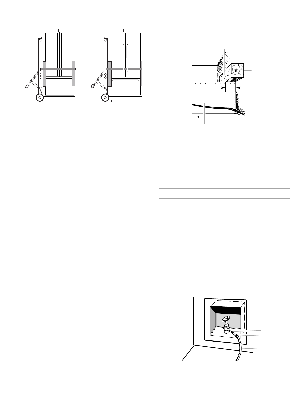
2. Securely attach one or two 2" x 4" x 32" (5 cm x 10 cm x
81 cm) boards to wall studs behind refrigerator. Use six
#8 x 3" (7.6 cm) (or longer) wood screws. The wood screws
must be screwed into the studs at least 1½" (3.8 cm). The
board(s) must overlap the compressor cover.
BA
2" (5 cm)
D
A. Center board
B. Two 2" x 4" x 32" (5 cm x 10 cm x 81 cm) boards
C. Attach to studs with six #8 x 3" (7.6 cm) screws
D. Compressor cover
¹⁄₄
" (6.35 mm) max. above refrigerator
Install Anti-Tip Boards
IMPORTANT:
■ To avoid tipping during use, the solid soffit must be within
1" (2.5 cm) maximum above the refrigerator. If the solid soffit is
higher than 1" (2.5 cm) or one is not available, then the
refrigerator must be braced.
■ It is recommended that board(s) be installed before the
refrigerator is installed.
■ Board(s) must be long enough to fully cover the width of the
compressor cover.
■ Locate the board(s) so the bottom surface(s) of the board(s)
is(are) 84" (213 cm) from the floor.
■ During installation, raise the refrigerator up so there is
¹⁄₄" (6.35 mm) maximum between the top of the refrigerator
and the bottom of the anti-tip board(s). Do not crush the
compressor cover when raising the rear leveling legs.
To Install Anti-tip Boards
1. Mark the stud locations on rear wall 80" to 90" (203 cm to
229 cm) above floor.
Connect the Water Supply
Read all directions before you begin.
IMPORTANT: If you turn the refrigerator on before the water line is
connected, turn the ice maker OFF.
Connect to Water Line
Parts Needed:
■ Minimum 7 ft (2.13 m) flexible, codes approved water
supply line
Style 1 - Shutoff Valve Connection
NOTE: If your water line connection does not look like Style 1, see
“Style 2 - Copper Line Connection.”
1. Unplug refrigerator or disconnect power supply.
IMPORTANT: Before attaching the tubing to shutoff valve, flush
the main water supply line to remove particles and air in the water
line. Allow enough flow so that water becomes clear. Flushing the
water line may help avoid filters and/or water valves from
becoming clogged.
2. Connect the flexible, codes approved water supply line to the
water shutoff valve by threading the provided nut onto the
shutoff valve as shown.
NOTE: The shutoff valve shown is in the side cabinet as
recommended.
A. Bulb
B. Nut
C. Water tubing
21
3. Place the end of the tubing into a bucket, and turn shutoff
A
B
C
D
E
F
G
valve ON.
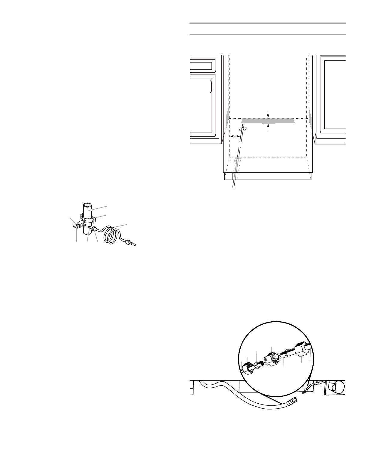
Connect to Refrigerator
4. Check for leaks. Tighten any nuts or connections (including
connections at the valve) that leak.
Parts Supplied:
■ ¹⁄₄" to ¹⁄₄" (6.35 mm to 6.35 mm) male-to-male coupling
Style 2 - Copper Line Connection
NOTE: If there is a water supply line that meets the specifications
in “Water Supply Requirements,” proceed to “Connecting to
Refrigerator.” If not, use the following instructions to connect to
the household cold water supply.
1. Unplug refrigerator or disconnect power.
2. Turn OFF main water supply. Turn ON nearest faucet long
enough to clear line of water.
3. Locate a ½" to 1¹⁄₄" (1.25 cm to 3.18 cm) vertical cold water
pipe near the refrigerator.
IMPORTANT:
■ Make sure it is a cold water pipe.
■ Horizontal pipe will work, but drill on the top side of the
pipe, not the bottom. This will help keep water away from
the drill and keep normal sediment from collecting in the
7"
(17.78 cm)
valve.
4. Determine the length of copper tubing you need. Measure
from the connection on the lower left rear of refrigerator to the
water pipe. Add 7 ft (2.1 m) to allow for cleaning. Use ¹⁄₄"
(6.35 mm) O.D. (outside diameter) copper tubing. Be sure both
ends of copper tubing are cut square.
5. Using a cordless drill, drill a ¹⁄₄" (6.35 mm) hole in the cold
water pipe you have selected.
G
A
B
C
NOTE: The flexible, codes approved water supply line can
connect to the supply valve through the floor or through the side
cabinets, as indicated by the gray boxes above.
1. Unplug the refrigerator or disconnect power.
2. Connect the 7 ft (2.13 m) flexible codes approved water tube
to the water supply valve.
3. Flush the main water supply line to remove particles and air in
the water line. Allow enough flow so that water becomes clear.
DEF
A. Cold water pipe
B. Pipe clamp
C. Copper tubing
D. Compression nut
E. Compression sleeve
F. Shutoff valve
G. Packing nut
6. Fasten the shutoff valve to the cold water pipe with the pipe
clamp. Be sure the outlet end is solidly in the ¹⁄₄" (6.35 mm)
drilled hole in the water pipe and that the washer is under the
pipe clamp. Tighten the packing nut. Tighten the pipe clamp
screws slowly and evenly so washer makes a watertight seal.
Do not overtighten.
IMPORTANT: Before attaching the tubing to shutoff valve, flush
4. Tape the 7 ft (2.13 m) flexible codes approved water supply
line to the floor, 7" (17.78 cm) from the left side of the
refrigerator. Tape along the length of the tubing, which will
allow it to pass beneath the refrigerator without interference.
NOTE: Allow a minimum of 26" (66.04 cm) of flexible codes
approved water supply line to be loose at the front of the
refrigerator for connecting to the refrigerator.
5. Connect the 7 ft (2.13 m) flexible codes approved water
supply line to the refrigerator.
NOTE: If the main water shutoff valve is behind the
refrigerator, a secondary water shutoff valve may be installed
in line with the water supply line at the front of the product.
the main water supply line to remove particles and air in the water
line. Allow enough flow so that water becomes clear. Flushing the
water line may help avoid filters and/or water valves from
becoming clogged.
7. Slip the compression sleeve and compression nut on the
copper tubing as shown. Insert the end of the tubing into the
outlet end squarely as far as it will go. Screw compression nut
onto outlet end with adjustable wrench. Do not overtighten the
clamp or the sleeve. This will crush the copper tubing.
8. Turn off the shutoff valve on the water pipe. Coil the copper
tubing.
9. Connect the flexible, codes approved water supply line to the
water shutoff valve by threading the provided nut onto the
shutoff valve.
10. Place the end of the tubing into a bucket, and turn shutoff
valve ON.
11. Check for leaks around the saddle valve. Tighten any nuts or
connections (including connections at the valve) that leak.
A. Household water line
B. Nut (purchased)
C. Ferrule (purchased)
D. Coupling
6. Turn on the water supply valve and check all connections for
leaks.
1"
(2.54 cm)
E. Bulb
F. N ut
G. Refrigerator water tubing
22
Plug in Refrigerator
A
B
Level and Align Refrigerator
WARNING
Electrical Shock Hazard
Plug into a grounded 3 prong outlet.
Do not remove ground prong.
Do not use an adapter.
Do not use an extension cord.
Failure to follow these instructions can result in death,
fire, or electrical shock.
1. Set control switch at top of cabinet to the OFF position.
2. Plug into a grounded 3 prong outlet.
Move Refrigerator to Final Location
WARNING
WARNING
Tip Over Hazard
Refrigerator is top heavy and tips easily when not
completely installed.
Keep doors taped closed until refrigerator is
completely installed.
Use two or more people to move and install
refrigerator.
Failure to do so can result in death or serious injury.
IMPORTANT: All four leveling legs must contact the floor to
support and stabilize the full weight of refrigerator. Rollers are for
moving refrigerator and not for permanent support.
After moving the refrigerator to its final location:
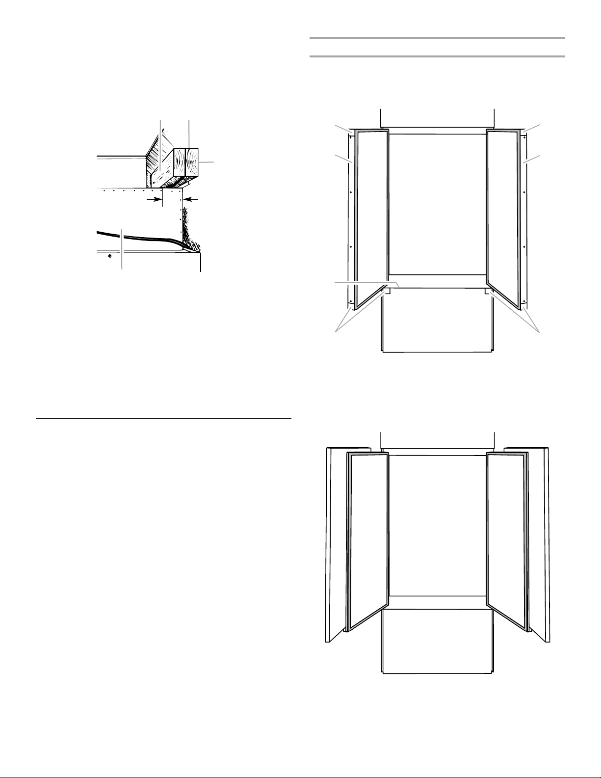
1. Use a ⁵⁄₁₆" socket driver to turn the leveling bolts clockwise to
extend the legs to the floor as shown. The rollers should be off
the floor.
Tip Over Hazard
Refrigerator is top heavy and tips easily when not
completely installed.
Keep doors taped closed until refrigerator is
completely installed.
Use two or more people to move and install
refrigerator.
Failure to do so can result in death or serious injury.
IMPORTANT: To avoid floor damage, make sure levelers are
raised (not touching floor) and refrigerator is on rollers before
moving.
1. Place top of cardboard carton or plywood under refrigerator.
Remove dolly.
2. Do not remove film or cover.
3. Move the refrigerator straight back and evenly into the
opening. Be sure that the refrigerator side trims are not
interfering with the door opening. Also, be sure that the water
tubing is not kinked and the power supply cord is on top of the
refrigerator.
A B
A. Rear leveling bolt
B. Front leveling bolt
2. Adjust the leveling legs to level and align the refrigerator from
left to right and front to back so that the refrigerator is level
and aligned with the cabinetry. The cabinetry surface must be
plumb for the ideal fit of the refrigerator side trim.
23
3. Continue adjusting all of the leveling legs to raise the
B
A
A
A
refrigerator until the top is within at least 1" (2.54 cm) of the
top soffit.
NOTE: If an anti-tip board has been used, adjust the leveling
legs until the top of the refrigerator is within ¹⁄₄" (6.35 mm) of
the bottom of the anti-tip board as shown. Do not crush the
compressor cover.
BA
Door Panel Installation
1. Remove all tape and door bracing from the refrigerator door(s)
and freezer drawer.
2. Open the refrigerator door(s) and freezer drawer and remove
the trims and corner caps on each door as shown.
A
C
¹⁄₄" (6 mm)
max.
2" (5 cm)
D
A. Center board
B. Two 2" x 4" x 32" (5 cm x 10 cm x 81 cm) boards
C. Attach to studs with six #8 x 3" (7.6 cm) screws
D. Compressor cover
¹⁄₄
" (6.35 mm) max. above refrigerator
IMPORTANT: Adjust in small increments to keep from
damaging the cabinet trim and causing problems with the
door alignment or top grille fit. To avoid damage to the cabinet
or leveling legs, do not apply more than 50 inch-pounds
(5.65 Nm) of torque to the leveling bolts. The leveling legs can
be extended to a maximum of 1¹⁄₄" (3.18 cm) below the rollers.
4. For Classic and Overlay models, additional adjustments may
be needed after the custom panels are installed.
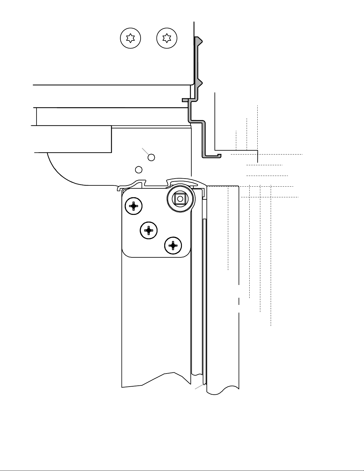
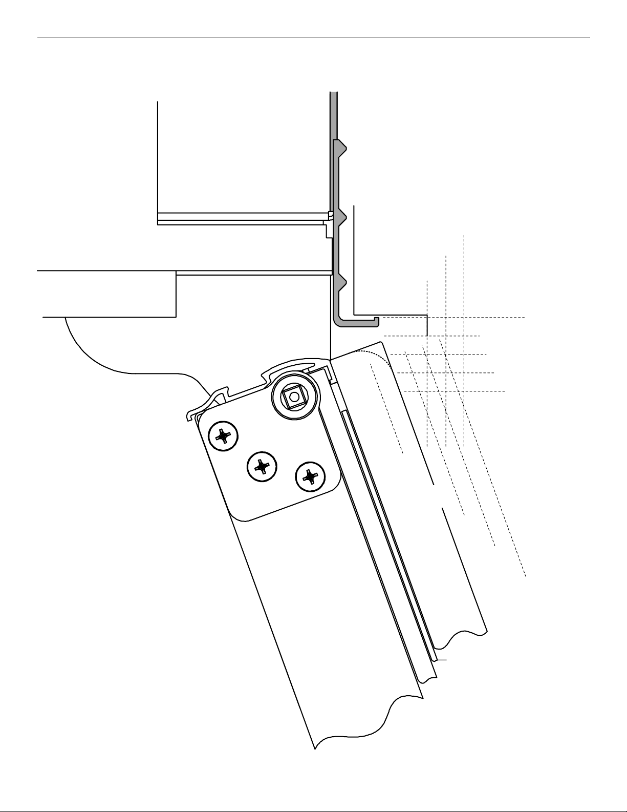
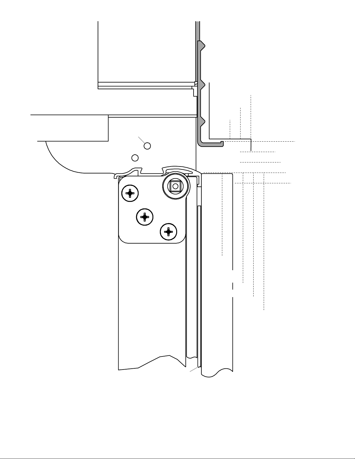
Install Overlay and Classic Series
Custom Panels
IMPORTANT:
■ Install the custom handles prior to installing the panels on
the refrigerator. For more information on KitchenAid
custom handle selection, refer to the KitchenAid Catalog,
visit www.kitchenaid.com, or call 1-800-422-1230.
In Canada, visit www.KitchenAid.ca, or call
1-800-807-6777.
■ Create custom door overlay panels according to the
specifications in the “Overlay Series Custom Panels”
section.
■ KitchenAid is not responsible for the removal or addition of
molding or decorative panels that would not allow access
to the refrigerator for service.
B
C
A
A. Corner caps
B. Refrigerator door trims
C. Freezer drawer trim
3. Slide the custom panels into the trims on the refrigerator
door(s) and freezer drawer, making sure that the backer panel
fits into the hinge side trims.
A
24
A. Panels
 Loading...