

KitchenAid KBFC42FS, KBFO42FS Technical Education

TECHNICAL EDUCATION
JOB AID 4317402
KAR-17
BUILT-IN FRENCH DOOR
BOTTOM-MOUNT
REFRIGERATOR
MODELS: KBFC42FS & KBFO42FS

FORWARD
This KitchenAid Job Aid, “Built-In French Door Bottom-Mount Refrigerator” (Part No.4317402),
provides the In-Home Service Professional with information on the installation, operation, and
service of the Built-In French Door Bottom-Mount Refrigerator. For specific information on the
model being serviced, refer to the “Use and Care Guide,” or “Tech Sheet” provided with the refrigerator
The Wiring Diagrams used in this Job Aid are typical and should be used for training purposes
only. Always use the Wiring Diagram supplied with the product when servicing the refrigerator.
.
GOALS AND OBJECTIVES
The goal of this Job Aid is to provide information that will enable the In-Home Service Professional
to properly diagnose malfunctions and repair the Built-In French Door Bottom-Mount Refrigera-
.
tor
The objectives of this Job Aid are to:
• Understand and follow proper safety precautions.
• Successfully troubleshoot and diagnose malfunctions.
• Successfully perform necessary repairs.
• Successfully return the refrigerator to its proper operational status.
WHIRLPOOL CORPORATION assumes no responsibility for any repairs made on
our products by anyone other than authorized In-Home Service Professionals.
Copyright © 2006, Whirlpool Corporation, Benton Harbor, MI 49022
- ii -

TABLE OF CONTENTS
Page
GENERAL . . . . . . . . . . . . . . . . . . . . . . . . . . . . . . . . . . . . . . . . . . . . . . . . . . . . . . . . . . . . . . 1-1
Refrigerator Safety
Model & Serial Number Designations . . . . . . . . . . . . . . . . . . . . . . . . . . . . . . . . . . . . . . . 1-2
Model & Serial Number Label And Tech Sheet Locations . . . . . . . . . . . . . . . . . . . . . . . . 1-3
ALLATION INFORMATION . . . . . . . . . . . . . . . . . . . . . . . . . . . . . . . . . . . . . . . . . . . . . 2-1
INST
ater Supply Requirements . . . . . . . . . . . . . . . . . . . . . . . . . . . . . . . . . . . . . . . . . . . . . . 2-1
W
. . . . . . . . . . . . . . . . . . . . . . . . . . . . . . . . . . . . . . . . . . . . . . . . . . . . . . 1-1
PRODUCT OPERA
Theory Of Operation . . . . . . . . . . . . . . . . . . . . . . . . . . . . . . . . . . . . . . . . . . . . . . . . . . . . 3-1
Refrigerator Use
COMPONENT ACCESS . . . . . . . . . . . . . . . . . . . . . . . . . . . . . . . . . . . . . . . . . . . . . . . . . . . 4-1
Component Locations . . . . . . . . . . . . . . . . . . . . . . . . . . . . . . . . . . . . . . . . . . . . . . . . . . . 4-1
Removing
Removing
Removing
Removing
Removing
Removing
Removing
Removing
Removing
Removing
Removing
Removing
Removing
Removing
Removing
Removing
Removing
Removing
Removing
A Refrigerator Light Socket . . . . . . . . . . . . . . . . . . . . . . . . . . . . . . . . . . . . . . . 4-3
The User Interface Assembly . . . . . . . . . . . . . . . . . . . . . . . . . . . . . . . . . . . . . 4-4
The Refrigerator Thermistor . . . . . . . . . . . . . . . . . . . . . . . . . . . . . . . . . . . . . . 4-5
The Refrigerator Motorized Air Door . . . . . . . . . . . . . . . . . . . . . . . . . . . . . . . . 4-6
A Refrigerator Temp-Controlled Motorized Air Door . . . . . . . . . . . . . . . . . . . . 4-7
A Temp-Controlled Drawer Cover . . . . . . . . . . . . . . . . . . . . . . . . . . . . . . . . . . 4-8
The Heated Flipper Mullion And An Actuator/Electrical Contact . . . . . . . . . . 4-10
The Unit Compartment Components . . . . . . . . . . . . . . . . . . . . . . . . . . . . . . 4-12
A Refrigerator Door Switch . . . . . . . . . . . . . . . . . . . . . . . . . . . . . . . . . . . . . . 4-17
A Refrigerator Door Skin And Handle . . . . . . . . . . . . . . . . . . . . . . . . . . . . . . 4-18
A Refrigerator Door . . . . . . . . . . . . . . . . . . . . . . . . . . . . . . . . . . . . . . . . . . . . 4-19
The Freezer Drawer Slides . . . . . . . . . . . . . . . . . . . . . . . . . . . . . . . . . . . . . . 4-20
The Freezer Drawer Switch . . . . . . . . . . . . . . . . . . . . . . . . . . . . . . . . . . . . . 4-21
The Ice Maker & Fill Tube Heater . . . . . . . . . . . . . . . . . . . . . . . . . . . . . . . . . 4-22
The Ice Maker Optics . . . . . . . . . . . . . . . . . . . . . . . . . . . . . . . . . . . . . . . . . . 4-24
The Evaporator Fan Motor . . . . . . . . . . . . . . . . . . . . . . . . . . . . . . . . . . . . . . 4-26
The Bimetal, Defrost Heater, And Evaporator . . . . . . . . . . . . . . . . . . . . . . . . 4-27
The Water Valve . . . . . . . . . . . . . . . . . . . . . . . . . . . . . . . . . . . . . . . . . . . . . . 4-30
The Water Filter Housing . . . . . . . . . . . . . . . . . . . . . . . . . . . . . . . . . . . . . . . 4-31
TION . . . . . . . . . . . . . . . . . . . . . . . . . . . . . . . . . . . . . . . . . . . . . . . . . . . 3-1
. . . . . . . . . . . . . . . . . . . . . . . . . . . . . . . . . . . . . . . . . . . . . . . . . . . . . . . . 3-9
- iii -

COMPONENT TESTING . . . . . . . . . . . . . . . . . . . . . . . . . . . . . . . . . . . . . . . . . . . . . . . . . . . 5-1
Thermistor . . . . . . . . . . . . . . . . . . . . . . . . . . . . . . . . . . . . . . . . . . . . . . . . . . . . . . . . . . . . 5-1
Heated Flipper Mullion
. . . . . . . . . . . . . . . . . . . . . . . . . . . . . . . . . . . . . . . . . . . . . . . . . . . 5-2
Motorized Air Door . . . . . . . . . . . . . . . . . . . . . . . . . . . . . . . . . . . . . . . . . . . . . . . . . . . . . . 5-2
Power Switch
. . . . . . . . . . . . . . . . . . . . . . . . . . . . . . . . . . . . . . . . . . . . . . . . . . . . . . . . . . 5-3
24V Transformer . . . . . . . . . . . . . . . . . . . . . . . . . . . . . . . . . . . . . . . . . . . . . . . . . . . . . . . 5-3
Condenser Fan Motor . . . . . . . . . . . . . . . . . . . . . . . . . . . . . . . . . . . . . . . . . . . . . . . . . . . 5-4
Evaporator Fan Motor . . . . . . . . . . . . . . . . . . . . . . . . . . . . . . . . . . . . . . . . . . . . . . . . . . . 5-4
Compressor & Inverter
Door/Drawer Switch
. . . . . . . . . . . . . . . . . . . . . . . . . . . . . . . . . . . . . . . . . . . . . . . . . . . 5-5
. . . . . . . . . . . . . . . . . . . . . . . . . . . . . . . . . . . . . . . . . . . . . . . . . . . . . 5-6
Fill Tube Heater . . . . . . . . . . . . . . . . . . . . . . . . . . . . . . . . . . . . . . . . . . . . . . . . . . . . . . . . 5-6
Defrost Heater & Bimetal
. . . . . . . . . . . . . . . . . . . . . . . . . . . . . . . . . . . . . . . . . . . . . . . . . 5-7
Water Valve . . . . . . . . . . . . . . . . . . . . . . . . . . . . . . . . . . . . . . . . . . . . . . . . . . . . . . . . . . . 5-7
Main Control Board . . . . . . . . . . . . . . . . . . . . . . . . . . . . . . . . . . . . . . . . . . . . . . . . . . . . . 5-8
DIAGNOSTICS & TROUBLESHOOTING . . . . . . . . . . . . . . . . . . . . . . . . . . . . . . . . . . . . . . 6-1
WIRING DIAGRAMS . . . . . . . . . . . . . . . . . . . . . . . . . . . . . . . . . . . . . . . . . . . . . . . . . . . . . . 7-1
TECH TIPS . . . . . . . . . . . . . . . . . . . . . . . . . . . . . . . . . . . . . . . . . . . . . . . . . . . . . . . . . . . . . . 8-1
Adjusting
Adjusting
A Refrigerator Door . . . . . . . . . . . . . . . . . . . . . . . . . . . . . . . . . . . . . . . . . . . . . 8-1
The Freezer Door . . . . . . . . . . . . . . . . . . . . . . . . . . . . . . . . . . . . . . . . . . . . . . . 8-2
- iv -

WARNING
DANGER
GENERAL
REFRIGERATOR SAFETY
Your safety and the safety of others are very important.
We have provided many important safety messages in this manual and on your appliance.
Always read and obey all safety messages.
This is the safety alert symbol.
This symbol alerts you to potential hazards that can kill or hurt you and others.
All safety messages will follow the safety alert symbol and either the word
“DANGER” or “WARNING.” These words mean:
You can be killed or seriously injured if you don’t
immediately follow instructions.
ou can be killed or seriously injured if you don’t
Y
follow instructions.
All safety messages will tell you what the potential hazard is, tell you how to reduce the
chance of injury, and tell you what can happen if the instructions are not followed.
1-1

MODEL & SERIAL NUMBER DESIGNATIONS
MODEL NUMBER
MODEL NUMBER K BF C 42 F S S 00
PRODUCT GROUP
K = KitchenAid
PRODUCT IDENTIFICATION
BF = BTM Freezer, French Door
MERCHANDISING SCHEME / SERIES
C = Wrap Around Stainless Steel
O = Overlay Model
WIDTH
42 = 42˝
MODEL FEATURES
F = Factory Installed Ice Maker & Filter
YEAR OF INTRODUCTION
S = 2006
COLOR CODE
X = No Color
S = Stainless
ENGINEERING CHANGE DIGITS
SERIAL NUMBER
SERIAL NUMBER Q T 21 10001
MANUFACTURING LOCATION
Q = LaVergne, TN
YEAR OF PRODUCTION
T = 2006
WEEK OF PRODUCTION
21st Week
PRODUCT SEQUENCE NUMBER
1-2

MODEL & SERIAL NUMBER LABEL
AND TECH SHEET LOCATIONS
The Model/Serial Number label and Tech Sheet locations are shown below.
Model & Serial Number Label Location
(On Upper Left Side Of Refrigerator Liner)
Tech Sheet Location
1-3

— NOTES —
1-4

INSTALLATION INFORMATION
WATER SUPPLY REQUIREMENTS
Water Pressure
A cold water supply with water pressure between 30 and 120 psi (207-827 kPa) is required
maker.
Reverse Osmosis Water Supply
IMPORTANT: The pressure of the water sup-
ply
going to the water inlet valve of the refrigerator
(207-827 kPa).
If
connected to your cold water supply, the water
needs to be a minimum of 40 psi.
to operate the water dispenser and ice
coming out of a reverse osmosis system
needs to be between 30 and 120 psi
a reverse osmosis water filtration system is
pressure to the reverse osmosis system
If the water pressure to the reverse osmosis
system is less than 40 to 60 psi (276-414 kPa):
Check to see whether the sediment filter
•
in the reverse osmosis system is blocked.
Replace the filter if necessary.
•
Allow the storage tank on the reverse osmosis system to refill after heavy usage.
the refrigerator has a water filter, it may
•
If
further reduce the water pressure when
used in conjunction with a reverse osmosis
system. Remove the water filter.
2-1

— NOTES —
2-2

PRODUCT OPERATION
Max Cool
Reset
Cooling
Door Open
Over Temperature
Call Service
Alarms
Holiday Mode Energy Saver
ON/OFF
THEORY OF OPERATION
THE ELECTRONIC CONTROL
OVERVIEW
The KitchenAid Built-In French Door BottomMount Refrigerator Constant Flow Temperature
Management System uses two thermistors
to monitor temperature changes inside the
refrigerator and freezer compartments. Two
electronic control boards are used in the re-
rigerator: a main electronic control board,
f
and a low voltage (Phoenix) board. The main
electronic control board manages the operation
of the variable capacity compressor (VCC), a
variable speed evaporator fan motor, and a
variable position air door. The air door allows
independent temperature control of the refrigerator and freezer compartments.
main electronic control board seeks the
The
most efficient means possible to maintain
temperatures as it controls the operation and
speed of the compressor and the evaporator
fan motor. Higher fan speed is used before
increasing the compressor speed to minimize
power consumption. A nearly constant run
time is sought at the lowest possible fan and
compressor speed.
Freezer
to –5°F (–15°C to –21°C). Refrigerator temperatures
to 1°C).
The
of the main electronic control board utilizes
“pulsed defrost” technology to perform the
defrost function (see page 3-4).
temperatures can be set from 5°F
can be set from 45°F to 33°F, (7°C
Adaptive Defrost Control (ADC) portion
PANEL
The main electronic control board monitors the
water valve for total elapsed time and gallons
of water used. The number displayed on the
Water Filter Indicator (WFI) is the percentage
of filter usage remaining.
The numeric display can be set for Fahrenheit
or Celsius and displays the actual temperatures.
The display range for the refrigerator is from
27°F to 70°F (–2.8°C to 21°C). The normal
freezer
–23°C
(
display range is from –10°F to 70°F
to 21°C). Temperatures above or below
these limits will be displayed at the correspond-
temperature limit. During Max Cool, the
ing
freezer display will read –5°F (–21°C), and the
refrigerator will read 34°F (1°C).
display will show the temperature setting
The
any time the actual temperature is within ±6°F
the customer setting. This will prevent con-
of
over temperature fluctuations when the
cern
doors are opened. The customer setting will
also be displayed during the defrost period,
and 30 minutes after defrost. Press the temperature
adjustment key to view the current
temperature setting, or to change the setting.
When the temperature adjustment key is used
to change the temperature setting, the display
will brighten for 5 seconds.
vailable features include:
A
Water Filter Indicator
•
Max Cool
•
Over-T
•
Holiday Mode
•
Energy Saver Mode
•
emperature Alarm
3-1

TEMPERATURE CONTROL
The main electronic control board checks the
resistance of the thermistors, and compares it
to both the customer temperature settings and
the last thermistor reading taken. This information
cooling operation, and if a change is necessary
in the damper setting, or the evaporator fan or
compressor speed.
When
ing mode, the air door partially opens, and the
compressor and evaporator fan motors start to
run at maximum rpm. The air door will gradually
move to its fully open position.
As
nears the selected temperature setting, the
electronic control compares the temperatures
in both compartments. The compartment that
has the greatest need for cooling will control
the speed of the evaporator fan motor.
Freezer Temperature Control —
Temperature Increasing
When the freezer calls for cooling, the compressor
the chart on page 3-3), and the evaporator fan
begins to run at 2000 rpm. The compressor and
evaporator speeds are continuously updated.
Speed changes are made based on:
•
•
If the temperature increases 4°F above the
selected
fan speed begins to gradually increase. The
evaporator fan motor reaches the maximum
speed of 3000 rpm at 5°F above the selected
emperature setting, and the compressor speed
t
begins to gradually increase. A maximum compressor
9°F above the selected temperature setting.
is used to determine when to begin a
a warm refrigerator is first put into a cool-
the actual temperature in the refrigerator
begins to run at minimum rpm, (see
difference between the actual tempera-
The
ture and the selected temperature settings.
The rate of temperature change.
temperature setting, the evaporator
speed of 4500 rpm will be reached at
Freezer Temperature Control —
Temperature Decreasing
When the freezer temperature begins to de-
rease, the process will reverse. The com-
c
ressor speed decreases, followed by the
p
evaporator fan speed.
Refrigerator T
Temperature Increasing
When the refrigerator calls for cooling while the
freezer is satisfied, the air door begins to open,
and the evaporator fan starts to run at minimum
speed. If the temperature continues to rise, the
air door will continue to open. If the temperature
continues to rise after the air door is fully open,
the evaporator fan speed will gradually increase
to a maximum of 3000 rpm. If the temperature
continues to rise, the compressor starts to run,
or if it has already been running, begins to in-
rease in speed.
c
Refrigerator Temperature Control —
Temperature Decreasing
As the refrigerator temperature approaches
the selected setting, the control compares the
temperatures in both compartments to determine
speed. If the freezer is further from the selected
temperature setting, it controls the fan speed,
and the air door begins to close, thus reducing
the airflow to the refrigerator.
If the freezer is satisfied, the air door remains
open, and the fan speed begins to decrease.
When the selected temperature setting is
reached, the air door closes.
which compartment will control the fan
emperature Control —
3-2
COMPRESSOR
COMPRESSOR PROTECTION
The main control board supplies a 5 vdc, peakto-peak square wave, at 54 to 150 Hz, to the
inverter board. A standard VOM will read approximately
plies
the variable capacity compressor with
2.5 vdc. The inverter board sup-
three-phase 230 vac. Varying the voltage and
frequency to the inverter board changes the
speed of the compressor. The compressor can
run at speeds of 1620 to 4500 rpm.
NOTE: It is not necessary, nor is it recommended, to test the output of the inverter board.
While
the compressor is running, its speed is
continuously updated. Speed is determined
after analyzing two factors:
difference between the actual tempera-
The
•
ture and the selected temperature settings.
The rate of temperature change.
•
Minimum compressor speed is based on the
freezer’s selected temperature setting, as
shown in the following chart.
Freezer Temperature Compressor
Setting (°F)
6 to –2 1620 rpm
–3 1800 rpm
–4 2000 rpm
–5 2200 rpm
compressor generally cycles on and off
The
Minimum Speed
according to the cut-in and cut-out temperatures
of the freezer, however, the refrigerator
can turn on the compressor if the evaporator
fan is at maximum speed and the refrigerator
temperatures are not dropping.
To protect the compressor and maintain efficiency, minimum compressor off time is pro-
rammed into the main control board. When the
g
compressor turns off, a minimum of 7 minutes
must elapse before allowing a restart.
t the end of the 7-minute period, the condenser
A
fan motor starts, and the main control board
sends the compressor speed signal to the
inverter. The compressor will not start for an
additional minute, due to the inverter delay.
The inverter utilizes a current-limiting device
and thermal protection that eliminates the need
for a compressor-mounted thermal protector.
The inverter will not allow a compressor restart
for 8 minutes after the compressor turns off.
This inverter delay will not occur after a power
interruption, because inverter memory is lost
(see “Power Interruption” on page 3-4).
EVAPORATOR FAN MOTOR
The evaporator fan motor is a 12 vdc, variable
speed motor. The motor has four wires:
A blue wire that is not used.
•
A red wire provides a constant 12 vdc.
•
A yellow wire provides a variable voltage
•
of between 5 vdc and 17 vdc to control the
motor speed from 2000 to 3000 rpm.
white wire provides a common return.
A
•
EVAPORATOR FAN &
AIR DOOR DELAY
After defrost, an evaporator fan delay prevents
unnecessary movement of warm, moist air
through the refrigerator by chilling the evapora-
prior to starting the fan. Immediately after
tor
defrost drip time, the compressor starts at
4500 rpm, but the evaporator fan is delayed for
8 minutes. Also, the air door remains closed
during the 8-minute delay.
3-3

AIR DOOR
The air door is driven by a reversible DC stepper
motor. The motor operates on a 12 vdc, peakto-peak square wave. Voltage is delivered to
the air door in a series of short pulses. It is not
possible to obtain a reliable voltage reading
with a VOM.
eparate windings are used to move the air door
S
open or closed. The door can be in any position
from 0 to 90 degrees. The air door is used to
fine-tune the airflow to the refrigerator.
The refrigerator temperature determines the
opening of the air door. When the refrigerator
requires cooling, if the evaporator fan motor
is already running for the freezer, the air door
partially opens, and then adjusts, if necessary.
While the refrigerator is cooling, the door will be
adjusting continuously to maintain or recover
refrigerator temperature.
ADAPTIVE DEFROST
The adaptive defrost control function of the main
electronic control board allows the refrigerator
to enter a defrost mode only when it is needed.
When powered up for the first time, the control
initiates a defrost cycle after 8 hours of compressor
of defrost heating time and compressor run
time, the control will continuously adapt the
time between defrosts to optimize efficiency.
Time between defrost periods will vary between
8 and 100+ hours.
efrost will occur immediately when the com-
D
pressor has run at 4000 rpm or greater for 1 hour,
and 8 hours have elapsed since the last defrost.
run time. By monitoring the duration
PULSED DEFROST
For the first 2 minutes of defrost, the heater is
on continuously. It will then cycle off for 1 min-
and back on for 2 minutes. The heater will
ute,
continue to cycle at this ratio until the bimetal
opens, or until 33 minutes has elapsed. At this
point, heat is discontinued, and a 4-minute “drip
time” begins. This allows the water to drain be-
the refrigerator returns to a cooling mode.
fore
Maximum defrost time, (pulsed heat on/off time
+ drip time) is 37 minutes.
When
is open, the time to defrost is reset to 8 hours,
and the control will time through the entire
37-minute defrost period. During diagnostics
this will allow a technician time to look for
heater operation, and if necessary, bypass
the bimetal.
entering a defrost cycle, if the bimetal
POWER INTERRUPTION
After a power interruption, the following events
will occur:
he refrigerator returns to the same operating
T
•
mode and settings in use prior to the power in-
erruption. If the unit was off, it remains off.
t
Initially, the compressor, evaporator fan, and
•
condenser fan motors will be off.
The air door will close, and then adjust to the
•
proper opening. The evaporator fan starts
when the air door opens.
he adaptive defrost control resets the
T
•
compressor run time counter to 0, and if the
freezer is above 20°F, the time to defrost is
set to 8 hours.
the freezer temperature is below 12°F
If
•
(
–11.1°C
delay of 7 minutes. If the freezer temperature
immediately
), the compressor starts after a
is above 12°F, the compressor starts
.
FAILURE DEFAULTS
In the event of a thermistor, or keypad failure,
the main electronic control board uses one of
the following default modes, which will continue
until the failure is corrected.
Refrigerator Thermistor
the main electronic control board senses an
If
open or a shorted thermistor, the air door and
the evaporator fan motor will begin to operate
on a timed on and off cycle, based on current
selected temperature settings. The evaporator
fan motor will run when the air door is open.
mid-settings of 37°F / 3°C, the air door will
At
open for 16 minutes, and close for 30 minutes.
Setting the freezer colder, or the refrigerator
warmer, will reduce the door-open time. Setting
the freezer warmer, or the refrigerator colder,
will increase the door-open time.
3-4

Freezer Thermistor
If the main electronic control board senses an
open or a shorted thermistor, the compressor
and the evaporator fan motor will begin to operate
time is based on current selected temperature
settings.
A
sor and the evaporator fan motors will run for
35 minutes, and be off for 25 minutes. Setting
the freezer colder will increase the run time.
Setting the freezer warmer will decrease the
run time.
The compressor will run at minimum speed.
The evaporator fan will also run at minimum
speed, unless the refrigerator compartment
requests a higher speed.
Keypad
I
the keypad is not working, it reverts to the default
refrigerator
Evaporator Fan Motor
If
compressor will run at 4500 rpm for an indefinite
period, except during the defrost periods.
on a timed on and off cycle. The cycle
t mid-settings of 37°F / 3°C, the compres-
f the main electronic control board detects that
temperature settings of 37°F (3°C) in the
, and 0°F (–18°C) in the freezer.
the evaporator fan motor malfunctions, the
MAX COOL MODE
Max Cool changes the refrigerator temperature setting to 34°F (1°C) and the freezer to
–5°F (–21°C) for 24 hours. During Max Cool,
freezer and refrigerator temperature dis-
the
plays
the actual temperatures.
In
than 1 hour. The control returns to the previo
temperature settings are changed.
show the new temperature settings, not
most cases the motors run 100% for more
us user setting after 24 hours, or any time the
AUTOMATIC MAX ICE
Automatic Max Ice operates any time the ice
maker water valve is energized. The duration
of Automatic Max Ice is 1-1/2 hours. During
Automatic Max Ice the following occurs:
•
•
•
•
freezer display shows the user tem-
The
perature settings and not the actual temperature.
freezer temperature setting changes to
The
–5°F (–21°C).
The evaporator fan runs at 3000 rpm.
The
compressor runs the entire 1-1/2 hour
mode. Speed is determined by the difference between actual freezer temperature
and –5°F (–21°C).
HOLIDAY MODE
The Holiday Mode may be used for the following occasions:
On vacation.
•
Religious observance (Sabbath Mode).
•
When the Holiday Mode is selected, the
•
corresponding backlit blue LED flashes for
5 seconds, and then remains on, to indicate
that the feature is activated.
3-5

In the Holiday Mode the following occurs:
Temperature selections remain at the current
•
setting, but are not displayed.
Water Filter Indicator is not displayed,
The
•
but monitoring continues.
The alarms are disabled.
•
The ice maker is disabled.
•
The interior lights are disabled.
•
T
he temperature displays and all of the LEDs
•
will be off, except for the Holiday Mode and
Cooling On/Off LEDs. The Holiday Mode and
Cooling On/Off LEDs will illuminate regardless of the door position.
eypad operation is disabled, with the excep-
K
•
tion
of the Holiday Mode key, or the Power
On/Off key.
MASTER ALARM RESET
Pressing the Over Temperature Reset will turn
off the audio alarm, but does not affect the indicator
Reset is pressed. The indicator light will turn off
once the Over Temperature Reset is pressed
a second time. The audio alarm will not sound
again for the current condition that caused the
alarm until a new condition occurs.
A
turning the power to the refrigerator off and
on again. The indicator light will turn on again
after the Over Temperature Reset is pressed,
if the condition that caused the alarm is still
present.
light the first time the Over Temperature
Master Alarm Reset can be performed by
CALL SERVICE ALARM
The Holiday Mode will be cancelled when the
following occurs:
Pressing
•
keypads.
hen the Holiday Mode is cancelled, the
W
Holiday Mode LED turns off, and the control
reverts to the settings in use prior to activation.
All inactive devices are restored, and the Water
Filter Indicator is updated.
Adaptive Defrost Control function contin-
The
ues during the Holiday Mode, but the control
will defrost at a fixed 12-hour interval.
the Power On/Off, or Holiday Mode
OVER TEMPERATURE ALARM
The Over Temperature Alarm sounds, and the
indicator light flashes when either the refrigera-
temperature exceeds 48°F (9°C), or the
tor
freezer
over
display flashes to show the user which compartment
temperature(s) returns to normal, but the red
Over Temperature LED will continue to flash
(refer to “Master Alarm Reset” to reset the Over
Temperature Alarm).
temperature exceeds 15°F (–9°C) for
1-1/2 hours. The appropriate temperature
is effected. The alarm stops if the
Call Service is a visual and audio signal that
alerts the user that the refrigerator needs
service. The Call Service Alarm will sound
when:
Either thermistor has failed.
•
over-temperature condition occurs for
An
•
3 hours or more.
Reset using Master Alarm Reset.
•
Communication is lost with either the low
•
voltage Phoenix or main electronic control
board.
DOOR OPEN ALARM
If any door is left open for more than 10 minutes, the interior lights will be disabled, the
Door Open icon will flash, and the alarm will
sound. If the door is closed during the alarm
operation, the alarm will reset.
SALES DEMONSTRATION MODE
This mode provides a sequential display of
the temperature displays and feature LEDs.
To enter the Demonstration Mode, press and
hold the Max Cool and Power On/Off keys for
2 seconds. If the refrigerator or freezer door
is open for 10 minutes, the interior lights will
turn off.
3-6

LOW VOLTAGE PHOENIX
CONTROL BOARD
A low voltage transformer, located on the left
side of the unit compartment, supplies 24 volts
ac to the Phoenix control board.
Phoenix control provides the following
The
functions:
ommunicates with both ingredient care
C
•
center pans.
Provides
•
center pans to operate the LED lighting in
each ingredient care center pan.
Monitors
•
center pan.
Controls
•
baffle for each ingredient care center pan.
Provides 24 volts dc to the heated flipper
•
mullion to prevent condensation on the flipper mullion.
Communicates
•
trol. This includes the status of the refrigerator
door switches and evaporator fan motor.
The two controls communicate and work together
control operates the ingredient care center
pan LED lighting and the mullion heater but it
does not get direct input on the position of the
refrigerator door switches. In order to operate
the LED pan lighting at the proper time, the
main control monitors the refrigerator door
switches and sends a communication on the
data line to let the Phoenix control know when
a refrigerator door is opened.
Phoenix control supplies 24 volts dc to the
The
mullion heater when both refrigerator doors are
closed. When a refrigerator door is opened, or
an ingredient care center pan air door change
is needed, the output of the Phoenix control
board is switched from the mullion heater to
the ingredient care center pan.
24 volts dc to both ingredient care
a thermistor in each ingredient care
the operation of the motorized air
with the main electronic con-
to provide proper function. The Phoenix
Ingredient Care Center
emperature Control
T
The control monitors the temperature of each
ingredient care center pan by means of a
thermistor located in the top of each pan.
When cooling is needed the Phoenix control
sends a request to the main control board to
operate the evaporator fan motor. The Phoenix
control board does not have direct control of
the evaporator fan motor. The Phoenix control
also sends a 12 vdc, peak to peak square wave
to the ingredient care center air door to open
the door.
The ingredient care center air door will be in
one of five possible positions based on the
ingredient care center user setting. The air
door will close at any setting when the proper
temperature has been reached. Here are the
four possible positions and temperatures for
each setting.
•
Closed.
When the refrigerator compartment is call-
ing
for cooling and the freezer is satisfied.
This allows the refrigerator to cool faster.
- Any setting when proper pan temperature
has been achieved.
When the refrigerator is in holiday mode.
-
- When the refrigerator is in defrost mode.
Deli—40°F, open at a 10° angle.
•
Produce—39°F, open at a 20° angle.
•
Meats—33°F, open at a 30° angle.
•
Quick Chill—25°F, open at a 45° angle.
•
When Quick Chill is selected, the pan
temperature is set to 25°F, and the freezer
temperature
evaporator
at high speed until the set temperature is
reached. When the hour has timed out, the
ingredient care center user interface and
the freezer temperature both return to the
previous customer settings.
is set to –5°F, for one hour. The
fan motor operates and runs
3-7

AIR CIRCULATION
In order to ensure proper temperatures, you
need to permit airflow between the refrigerator
and freezer sections. As shown in the illustra-
cool air enters the freezer section through
tion,
vents in the rear and top. The air flows forward
through the freezer section and recirculates
under the freezer floor. Cool air enters the refrigerator
and across shelves to the doors and recirculates
to return air vents at the bottom.
section through the top, flows down
is important not to block any of the vents with
It
food items. If the vents are blocked, airflow will
be restricted, and the temperature management
system will not function properly.
IMPORTANT: Because air circulates between
both sections, any odors formed in one section
will transfer to the other. Keep both sections
clean, and wrap or cover foods tightly to help
avoid the transfer of odors from food to ice.
3-8

REFRIGERATOR USE
MAX COOL
The Max Cool feature assists with periods of
heavy ice usage, full grocery loads, or temporarily warm room temperatures.
ress MAX COOL to turn on the Max Cool fea-
P
•
ture. The Max Cool indicator light will remain
on for 24 hours unless manually turned off.
NOTE: The temperature display will remain at
34°F (1°C) and –5°F (–21°C) for the refrigera-
or and freezer compartments, respectively,
t
while the Max Cool feature is enabled. After
24 hours, the refrigerator returns to the previous temperature set points.
HOLIDAY MODE
The Holiday Mode feature is designed for the
traveler or for those whose religious observanc-
require turning off the lights and ice maker.
es
By selecting this feature, the temperature set
points and Deli Pan settings remain unchanged,
the ice maker will be disabled and the interior
lights will turn off. For most efficient refrigerator
operation, it is recommended to exit the Holiday
Mode when it is no longer required.
ress HOLIDAY MODE to turn on the Holiday
P
•
Mode feature. This feature will remain on until
Holiday Mode is pressed again.
ENERGY SAVER™ FEATURE
(42˝ BOTTOM MOUNT ONLY)
The Energy Saver feature controls the heaters
located inside the hinged seal between the re-
rigerator doors. The heaters help keep external
f
moisture from forming on the hinged seal.
Press
•
this feature for low humidity conditions. The
ring around the control will be lit when Energy
Saver is on. If moisture begins to collect on
the hinged seal between the doors, press
ENERGY SAVER control again to turn off
this feature.
ENERGY SAVER control to turn on
ALARM FUNCTIONS
Master Alarm Reset
Pressing Alarm Reset once will turn off the audio
alarm and indicator light. The audio alarm will
not sound again for the current condition that
caused the alarm until a new condition occurs
or until a Master Alarm Reset is performed.
A Master Alarm Reset can be performed by
pressing Cooling (ON/OFF) twice or by turning
the power to the refrigerator off and on again.
After performing a Master Alarm Reset, the
indicator light will reactivate if the condition that
caused the alarm is still present.
NOTE: If the Max Cool feature has been selected
feature, then the set points will remain at 34°F
(1°C) and -5°F (-21°C) for the refrigerator and
freezer
Max Cool feature times out. The refrigerator
will then return to the previous temperature set
points chosen prior to the selection of the Max
Cool feature, but the lights and ice maker will
remain off until the Holiday Mode is pressed
again.
prior to turning on the Holiday Mode
compartments, respectively, until the
Door Open
The Door Open indicator light will flash, an
alarm will sound and the interior lights will turn
off when a door has been open for longer than
10 minutes. When the door is closed, the audio
alarm will reset and turn off, but the Door Open
indicator light will continue to flash until the
temperature is equal to or below 45°F (7°C)
15°F (-9°C) for the refrigerator and freezer
and
compartments, respectively
NOTE: T
dicator light, see “Master Alarm Reset.”
o deactivate the audio alarm and in-
.
3-9
Over Temperature
A. ON/OF F control
A
A. Crisper pans
B. Deli pans
A
B
B
IMPORTANT: If the Over Temperature Alarm
activates, your food may spoil (see “Power
Interruptions” in the Use and Care Guide for
additional information). Minimize door openings
until temperatures return to normal.
Over Temperature feature is designed to
The
let you know when either the refrigerator temperature
emperature rises above 15°F
t
rises above 48°F (9°C) or the freezer
(–9°C) for longer
than 1-1/2 hours. The audio alarm will shut off
automatically when the temperature returns
to normal, but the indicator light will continue
to flash until the Alarm is pressed to let you
know that an over temperature condition has
occurred.
the over temperature condition is still present
If
when an Over Temperature Reset is performed,
the indicator light will continue to reactivate
every 1-1/2 hours until refrigerator and freezer
temperatures are below 48°F (9°C) and 15°F
(–9°C), respectively.
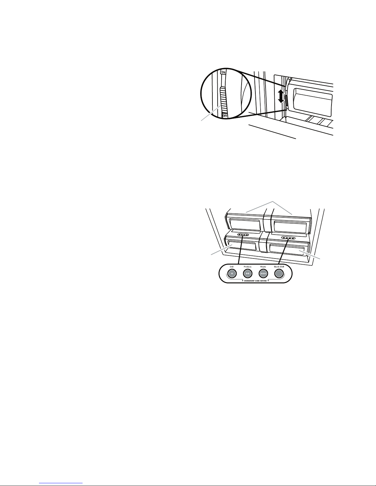
2. To manually turn off the ice maker, slide
the ice maker ON/OFF control to the OFF
(down) position as shown.
DELI/CRISPER PANS
The 42˝ (106.7 cm) model includes two deli pans
and two crisper pans, while the 36˝
model has one deli pan and one crisper pan.
(91.4 cm)
OTE: To deactivate the audio alarm and indi-
N
cator light, see “Master Alarm Reset.”
ICE MAKER
Turn the Ice Maker ON/OFF
The ice maker ON/OFF control is located on
the left-hand side of the ice bin.
To turn on the ice maker, slide the ice maker
1.
ON/OFF control to the ON (up) position.
NOTE: Your ice maker has an automatic
shutof
fill the ice storage bin. The ice maker sensors
but the ice maker control will remain in the
ON (up) position.
f. As ice is made, the ice cubes will
will automatically stop ice production,
Deli Pan Settings
Ingredient Care Center control panel lo-
The
cated above each deli pan has the following
three temperature settings: Deli, Produce,
Meats (Cold to Coldest) and the Quick Chill
setting. Select the appropriate setting for the
food being stored.
3-10

Meat Storage Guide
Quick Chill Setting
Store most meat in original wrapping as long
as it is airtight and moisture-proof. Rewrap if
necessary. When storing meat longer than the
times shown below, freeze the meat.
Fresh fish or shellfish: Use same day as purchased.
Chicken, ground beef, variety meat (liver, etc.): 1-2 days.
Cold cuts, steaks & roasts: 3-5 days.
Cured meats: 7-10 days.
Leftovers: Cover leftovers with plastic wrap, aluminum foil,
or plastic containers with tight lids.
Each deli pan has a Quick Chill setting. Activating this selection lowers the temperature of the
pan for a period of one hour.
NOTE: This will lower the deli pan temperature
below the freezing point for liquids.
3-11

— NOTES —
3-12
COMPONENT ACCESS
WARNING
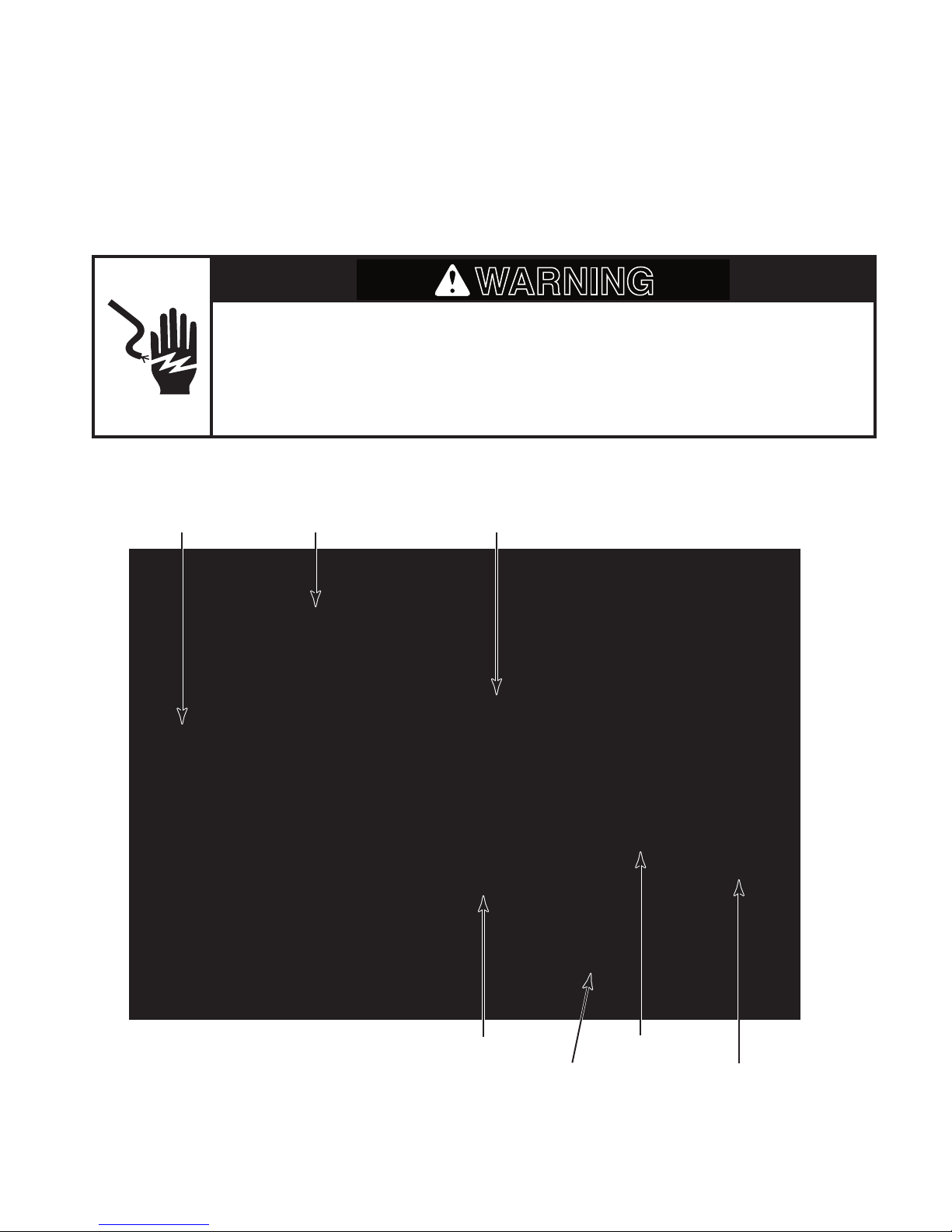
This section instructs you on how to service components inside the Built-In French Door BottomMount Refrigerator. The components and their locations are shown below.
COMPONENT LOCATIONS
Electrical Shock Hazard
Disconnect power before servicing.
Replace all parts and panels before operating.
Failure to do so can result in death or electrical shock.
Unit Compartment Components
Inverter
Compressor
Condenser Fan Motor
24V
Transformer
Power Switch
4-1
Main Control Board
Low Voltage Control Board
 Loading...