

KitchenAid JOB AID 4317282, KDRP407HSS Technical Education

KAC-29
TECHNICAL EDUCATION
PROFESSIONAL
DUAL FUEL RANGE
WITH SELF-CLEAN
THERMAL CONVECTION OVEN
JOB AID 4317282

FORWARD
This Job Aid, “Professional Dual Fuel Range With Self-Clean Thermal Convection Oven,” (Part
No. 4317282), provides the technician with information on the operation and service of the Professional Dual Fuel Range. It is to be used as a training Job Aid and Service Manual.
The wiring diagrams and strip circuits used in this Job Aid are typical and should be used for
training purposes only. Always use the wiring diagrams supplied with the product when servicing
the unit.
GOALS AND OBJECTIVES
The goal of this Job Aid is to provide detailed information that will enable the service technician to
properly diagnose malfunctions and repair the Professional Dual Fuel Range.
The objectives of this Job Aid are to:
• Understand and follow proper safety precautions.
• Successfully troubleshoot and diagnose malfunctions.
• Successfully perform necessary repairs.
• Successfully return the Professional Dual Fuel Range to the proper operational status.
WHIRLPOOL CORPORATION assumes no responsibility for any repair
made on our products by anyone other than Authorized Factory Service
Technicians.
Copyright 2001, Whirlpool Corporation, Benton Harbor, MI 49022
- ii -

Table of Contents
Page
SPECIFICATIONS .................................................................................................................. 1-1
COMPONENT ACCESS ......................................................................................................... 2-1
Component Locations ........................................................................................................ 2-1
Removing A Sealed Burner & Ignitor ................................................................................. 2-2
Removing The Control Power And Lamp Transformers, The Electronic
Range Control, The Oven Door Latch Assembly, & Spark Module ................................ 2-4
Removing The Front Panel, Display, Selector & Set Controls,
Gas Valve, & Ignition Switches ....................................................................................... 2-8
Removing A Halogen Lamp Assembly ............................................................................ 2-13
Removing The Broil Element ........................................................................................... 2-14
Removing The Oven Temperature Sensor ...................................................................... 2-15
Removing The Gas Regulator ......................................................................................... 2-16
Removing The Rear Panel .............................................................................................. 2-17
Removing The Convection Bake Element & Fan Motor Assembly.................................. 2-18
Removing The Blower Motor Assembly........................................................................... 2-20
Removing The Suppressor Board ................................................................................... 2-21
Removing The Oven Shutdown Thermal Fuse................................................................ 2-22
Removing The Hidden Bake Element.............................................................................. 2-23
Removing The Oven Door ............................................................................................... 2-25
Removing The Oven Door Glass, Hinges, & Handle ....................................................... 2-26
Removing The Oven Door Gasket................................................................................... 2-28
COMPONENT TESTING ........................................................................................................ 3-1
Electronic Range Control ................................................................................................... 3-1
Control Power & Lamp Transformers ................................................................................ 3-2
Blower Motor...................................................................................................................... 3-3
Oven Door Latch Assembly ............................................................................................... 3-4
Oven Temperature Sensor ................................................................................................ 3-5
Oven Shutdown Thermal Fuse .......................................................................................... 3-6
Convection Bake Element ................................................................................................. 3-7
Convection Fan Motor ....................................................................................................... 3-8
Broil Element ..................................................................................................................... 3-9
Hidden Bake Element ...................................................................................................... 3-10
Ignition Switches .............................................................................................................. 3-11
DIAGNOSIS & TROUBLESHOOTING.................................................................................... 4-1
Failure/Error Display Codes............................................................................................... 4-1
Electronic Range Control Pinouts ...................................................................................... 4-2
Electronic Range Control Component Test Points ............................................................ 4-3
Relay Logic ........................................................................................................................ 4-3
WIRING DIAGRAMS & STRIP CIRCUITS .............................................................................. 5-1
Oven Wiring Diagram ........................................................................................................ 5-1
Cooktop Wiring Diagram.................................................................................................... 5-1
Strip Circuits ...................................................................................................................... 5-2
TECH TIPS ............................................................................................................................. 6-1
Requesting Assistance Or Service .................................................................................... 6-1
Dual Fuel Range Warranty ................................................................................................ 6-2
- iii -
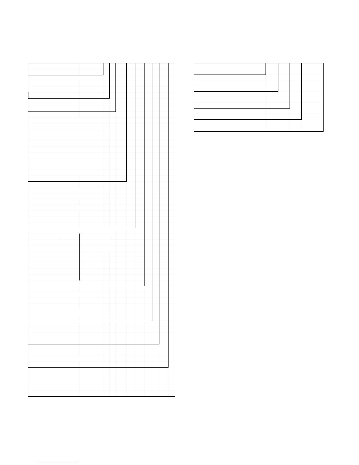
MODEL & SERIAL NUMBER DESIGNATIONS
MODEL NUMBER
MODEL NUMBER K DR P 40 7 H
INTERNATIONAL SALES IND.
or MARKETING CHANNEL
IF PRESENT
K = KITCHENAID BRAND
PRODUCT IDENTIFICATION
DD = DUAL FUEL DROP-IN / SLIDE-IN
DR = DUAL FUEL RANGE
ED = ELECTRIC DROP-IN RANGE
EE = ELECTRIC EYE-LEVEL RANGE
ER = ELECTRIC STANDARD RANGE
ES = ELECTRIC SLIDE-IN RANGE
GD = GAS DROP-IN RANGE
GE = GAS EYE-LEVEL RANGE
GR = GAS STANDARD RANGE
GS = GAS SLIDE-IN RANGE
MERCHANDISING SCHEME
C = CERAMIC GLASS TOP
H = CERAMIC WITH HALOGEN
I = IMPERIAL
P = PROFESSIONAL / COMMERCIAL
S = STANDARD TOP
T = TEMP. GLASS TOP
SS 0
SERIAL NUMBER
SERIAL NUMBER
MANUFACTURING SITE
X = OXFORD
YEAR OF MANUFACTURE
K = 2000
WEEK OF MANUFACTURE
PRODUCT SEQUENCE NUMBER
X K 05 10052
CAPACITY / SIZE / SERIES / CONFIGURATION
1ST POSITION 2ND POSITION
1 = DROP-IN 0 = 30" WIDE
2 = DROP-IN/SLIDE-IN 6 = 36" WIDE
COMBINATION
3 = SLIDE-IN
4 = COMMERCIAL
5 = STANDARD
7 = EYE-LEVEL
FEATURES
0 = STANDARD FEATURES
2 = PLUS FEATURES
5 = DELUXE FEATURES
7 = DELUXE FEATURES / CONVECTION
YEAR OF INTRODUCTION
H = 1999
J = 2000
COLOR CODE
SI - SILVER
SS = BRUSHED STAINLESS STEEL
ENGINEERING CHANGE
0 = Basic Release
1 = First Revision
2 = Second Revision
- iv -
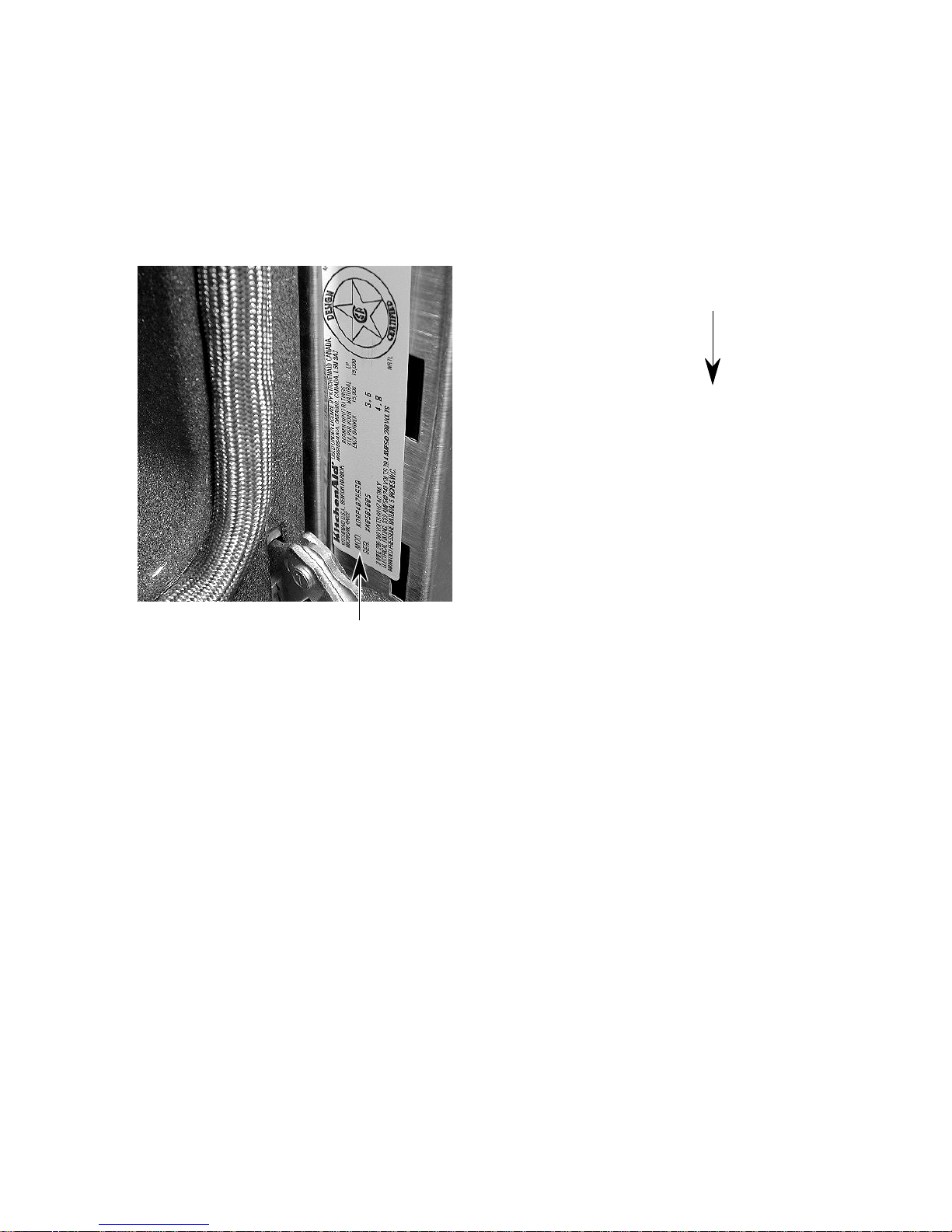
MODEL & SERIAL NUMBER LABEL
AND TECH SHEET LOCATIONS
The Model/Serial Number label and Tech Sheet locations are shown below. NOTE: The tech
sheet is accessible by removing the cooktop. To remove the cooktop, refer to page 2-2 for the
procedure.
Tech Sheet
Location
Model & Serial
Number Label Location
(On Right Side Of Chassis)
- v -

IMPORTANT SAFETY INFORMATION
Your safety and the safety of others is very important.
Important safety messages have been provided in this Job Aid. Always read and obey all
safety messages.
This is the safety alert symbol.
This symbol alerts you to hazards that can kill or hurt you and others.
All safety messages will be preceded by the safety alert symbol and the word
“WARNING.”
All safety messages will identify the hazard, tell you how to reduce the chance of injury, and tell
you what can happen if the instructions are not followed.
IMPORTANT
Electrostatic Discharge (ESD)
Sensitive Electronics
ESD problems are present everywhere. ESD may damage or weaken the electronic control assembly. The new control assembly may appear to work well after repair is finished,
but failure may occur at a later date due to ESD stress.
• Use an anti-static wrist strap. Connect the wrist strap to the green ground connection
point, or to an unpainted metal surface in the appliance.
- OR -
Touch your finger repeatedly to a green ground connection point, or to an unpainted
metal surface in the appliance.
• Before removing the part from its package, touch the anti-static bag to a green ground
connection point, or to an unpainted metal surface in the appliance.
• Avoid touching electronic parts, or terminal contacts. Handle the electronic control
assembly by the edges only.
• When repackaging the failed electronic control assembly in an anti-static bag, observe
the previous instructions.
- vi -
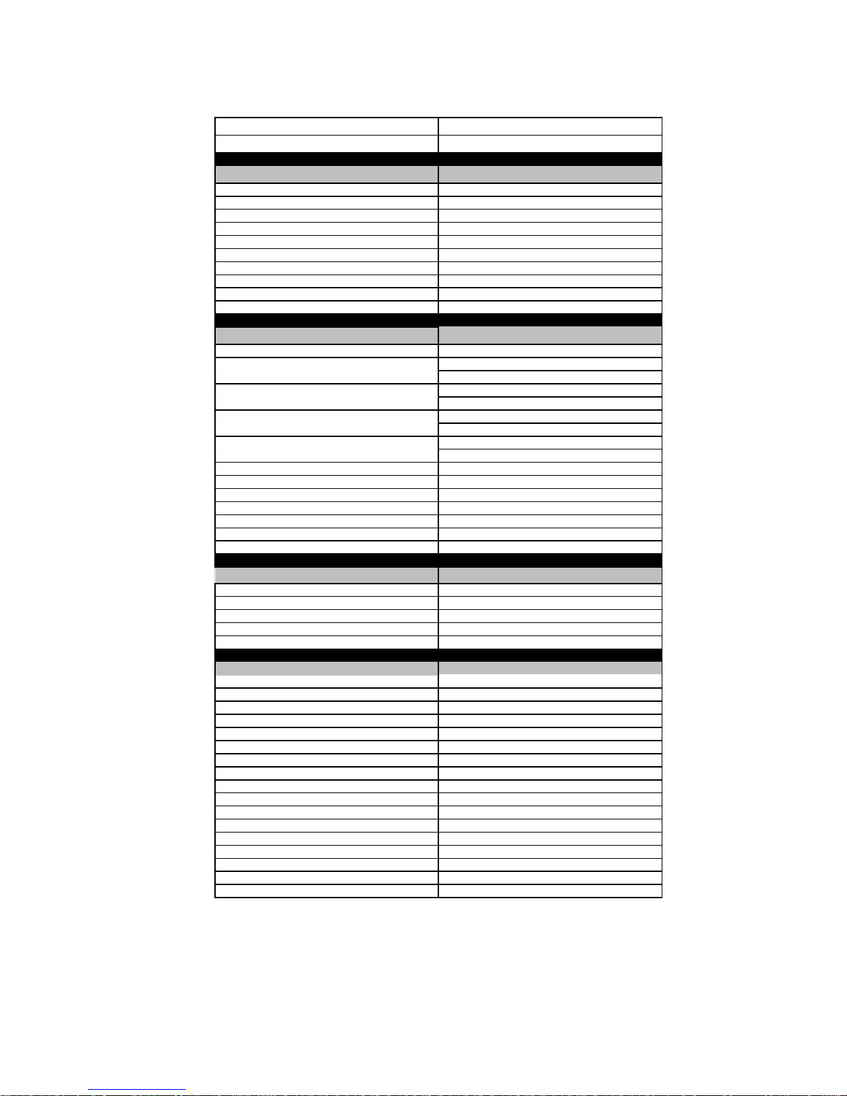
SPECIFICATIONS
SIZE 30"
NEW MODEL NUMBER KDRP407HSS
Controls
Push-To-Turn Yes -4
Infinite Yes - 4
Location Front/Vertical
Ignition System Electronic-Lite Position
Knobs Black-KA design-heavy duty
Control Panel Color Stainless
Landing Ledge Stainless-KA design
Oven "On" Light Yes
Oven Clean Light Yes
Hot Surface Indicators NA
Burners
Sealed Yes-4
Right Front 12,000 btu LP
Left Front 12,000 btu LP
Right Rear 12,000 btu LP
Left Rear 12,000 btu LP
Grates 2 Cast Iron-Full Surface
Color Matte Black
Burner/Grate Support None required
Burner Pan Black Porcelain
Filler Grate Cast Iron KA Design
Bezel No
Drip Bowl No
a
Surface
Porcelain/Metal Yes
9" Backsplash Standard-required
Cooktop Island Trim Optional
Drip Tray No
Color Stainless
15,000 btu natural
15,000 btu natural
15,000 btu natural
15,000 btu natural
Oven Control Features
Type Electronic with knob interface
Off Yes
Light Auto
Bake Yes
Broil Yes
Econo Broil No
Convection Bake Yes
Convection Broil Yes
Convection Roast Yes
Bread Raising Yes
Keep Warm Yes
Clean Yes
Browning Feature Three Level
Kitchen Timer Yes
Start No
Cancel/Off Yes
Oven Light Yes
1-1
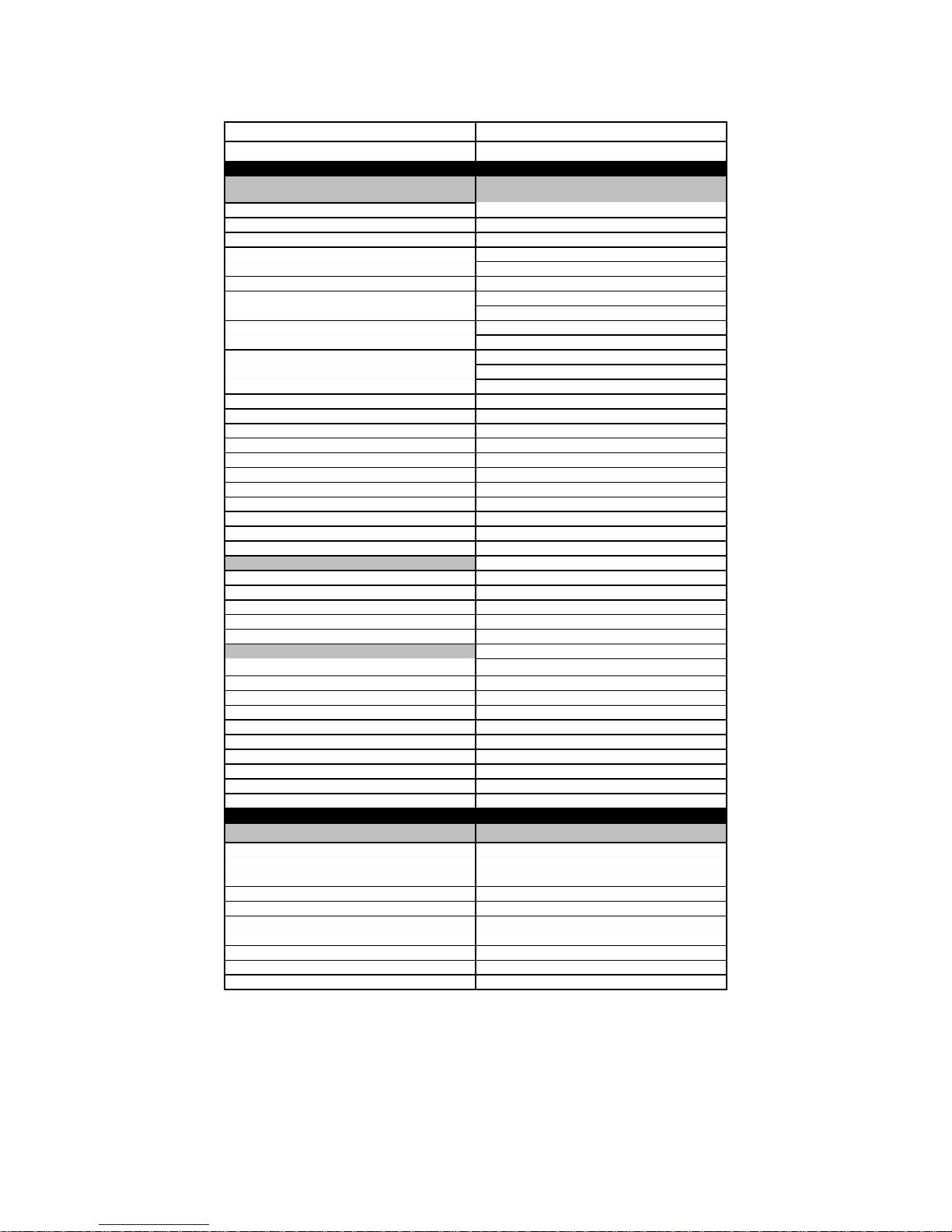
Specifications (continued)
SIZE 30"
NEW MODEL NUMBER KDRP407HSS
Other Upper Oven
Features
Oven Cleaning System Self Clean
Auto Self Clean Latch Yes
Hidden Bake Element Yes
Bake Element 2000w @ 240V
Broil Element 2667w @ 240V
1500w @ 208V
2000w @ 208V
Convection Element 1600w @ 240V
Size - Cavity 25"W X 16"H X 18 1/2"D
Cavity Volume-Cu. Ft. 4.24 Cu. Ft.
Oven Door/Liner Finish Porcelain
Integral Rack Guides Yes
Oven Racks 3
Broiler Pan and Grid Porcelain/Chrome KA
Roasting Rack Yes-KA Design
Window Glass Black
Removable Door Yes
Door Gasket Yes
Floating Glass No
Vent Color NA
Oven Features (Cont.)
Front Frame Porcelain
BottomTrim Stainless
Oven Lights Yes-2
Manual Light Yes
Auto Light Yes
Dimensions
Width (Side to Side)
Front 29 7/8"
Depth (Front to Back) 26 1/4"
Height (Top to Bottom) 36" Adjustable
Cutout
Width (Side to Side) 30 "
Depth (Front to Back) 24"-25 3/8"
Height (Top to Bottom) 36" Adjustable
Mounting Hardware No
1200w @ 208V
Other Specifications
Electrical 240/208 Volts,
Circuit 30 Amp
Total Conected Load "E"
Power Cord/Conduit Pigtail Required
Domestic Use Only Yes
Agency Approvals AGA/CGA
Approximate Shipping Weight 375 lbs.
Single Phase,
60 Hz
3 Wire
1-2
COMPONENT ACCESS
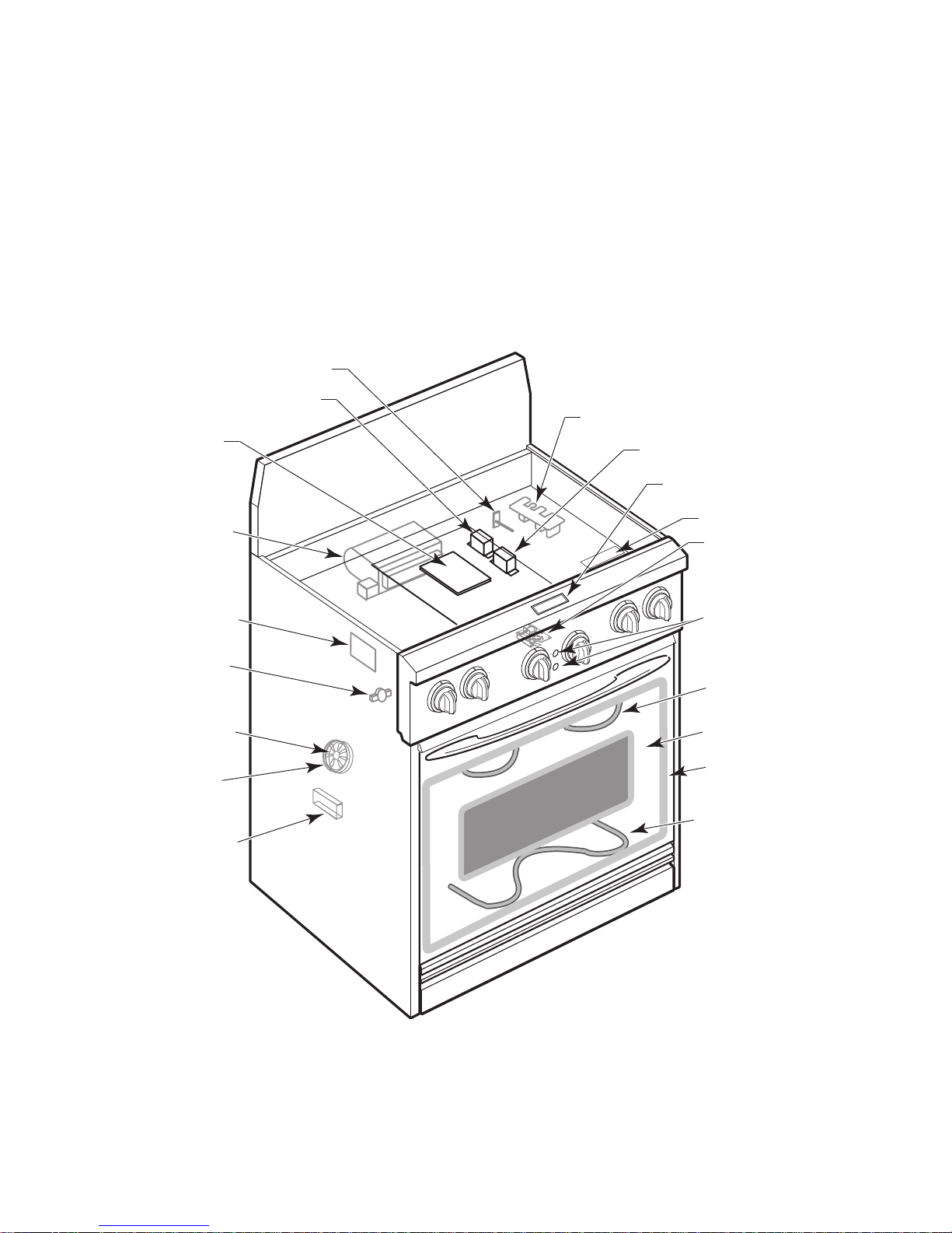
This section instructs you on how to service each component inside the range. The components
and their locations are shown below.
COMPONENT LOCATIONS
Oven Temperature Sensor
Lamp Transformer
Electronic
Range Control
Blower Motor
Tech Sheet
Oven Shutdown
Thermal Fuse
(On Rear Panel)
Convection
Fan Motor
Convection
Bake Element
Halogen Lamp
Suppressor (Mounted On
Terminal Block L1 & Neutral)
Control Power Transformer
Display
Spark Module
Door Latch Assembly
OFF
OFF
OFF
OFF
OFF
OFF
Set/Selection
Controls
Broil Element
Stainless Steel
Oven Door
Door Gasket
Hidden Bake Element
2-1
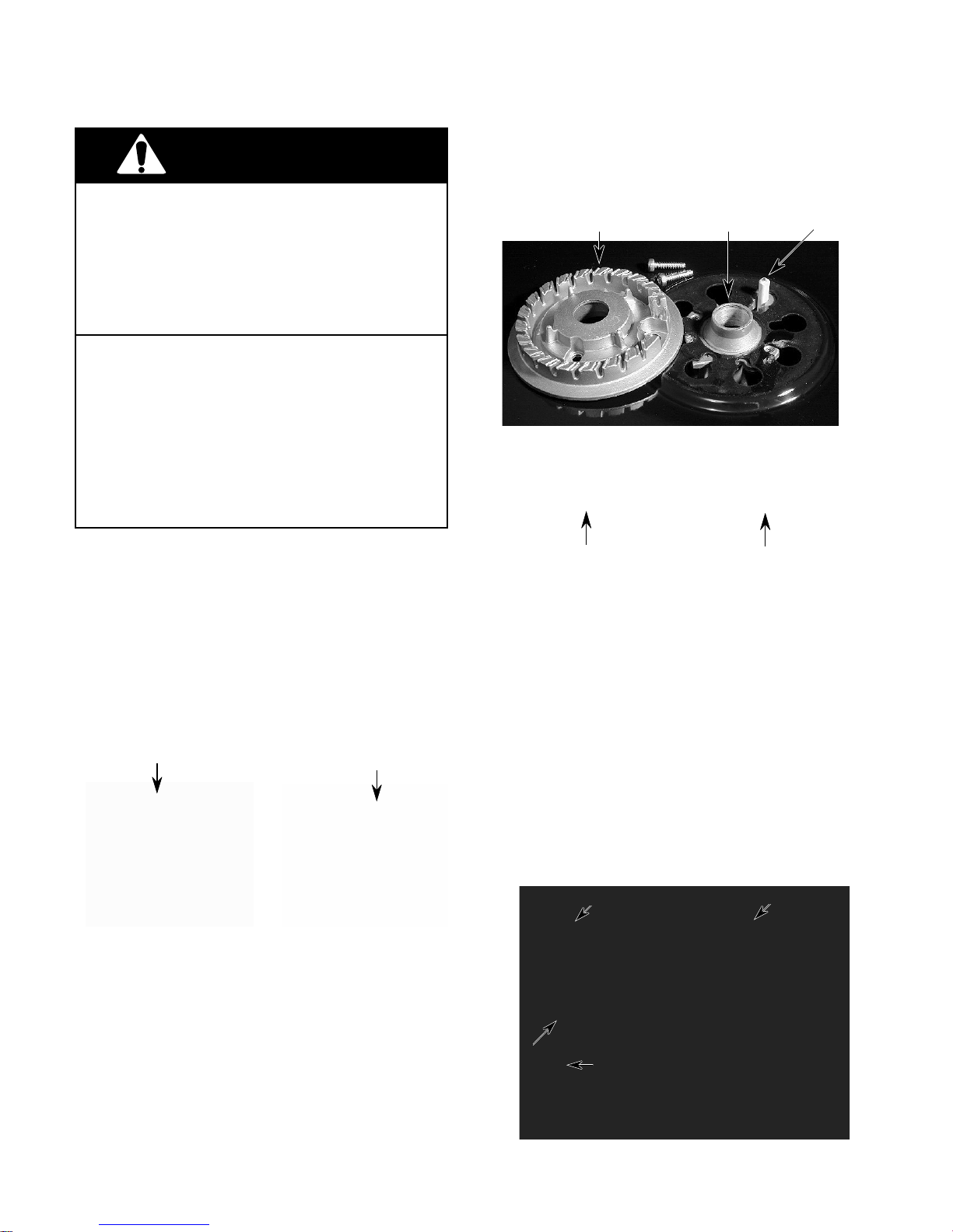
REMOVING A SEALED BURNER & IGNITOR
3. Use a T20 torx screwdriver and remove
WARNING
the two screws from each burner head,
then lift the heads off the cooktop.
ELECTRICAL SHOCK HAZARD
Disconnect power before servicing the range.
Replace all panels before operating range.
Failure to do so can result in death or electrical shock.
FIRE HAZARD
Shut off gas supply line valve before servicing the range.
Check all gas line connections and replace
all panels before operating the range.
Failure to do so could result in explosion, fire,
or other injury.
CAUTION: When you work on the dual fuel
range, be careful when handling the sheet
metal parts. Sharp edges may be present, and
you can cut yourself if you are not careful.
1. Turn off the gas and electrical power going
to the range.
Burner Head
Sealed
Burner
Ignitor
4. Lift the rear of the cooktop, slide it forward,
and remove it.
Lift Lift
Cooktop
2. Remove the grates and burner caps from
the cooktop.
Grate
Burner Cap
5. To remove an ignitor from a sealed
burner:
a) Disconnect the ignitor wire from the
terminal.
b) Remove the screw from the ignitor
bracket.
Sealed Burner
Ignitor
Screw
Ignitor
Ignitor
Wire
2-2
6. To remove a sealed burner:
a) Disconnect the ignitor wire from the
ignitor terminal (see step 5).
b) Use a 1/2˝ open-end or an adjustable
wrench and remove the gas line fitting
from the sealed burner you are replacing.
Burner
Head
c) Remove the two hex-head screws from
the burner bracket and remove the
sealed burner.
d) Remove the screw from the ignitor
bracket and remove the ignitor from the
sealed burner.
Ignitor
Screw
Bracket
Hex-Head
Screws
Burner
Head
1/2˝ Gas Line Fitting
2-3
REMOVING THE CONTROL POWER AND LAMP
TRANSFORMERS, THE ELECTRONIC RANGE CONTROL,
THE OVEN DOOR LATCH ASSEMBLY, & SPARK MODULE
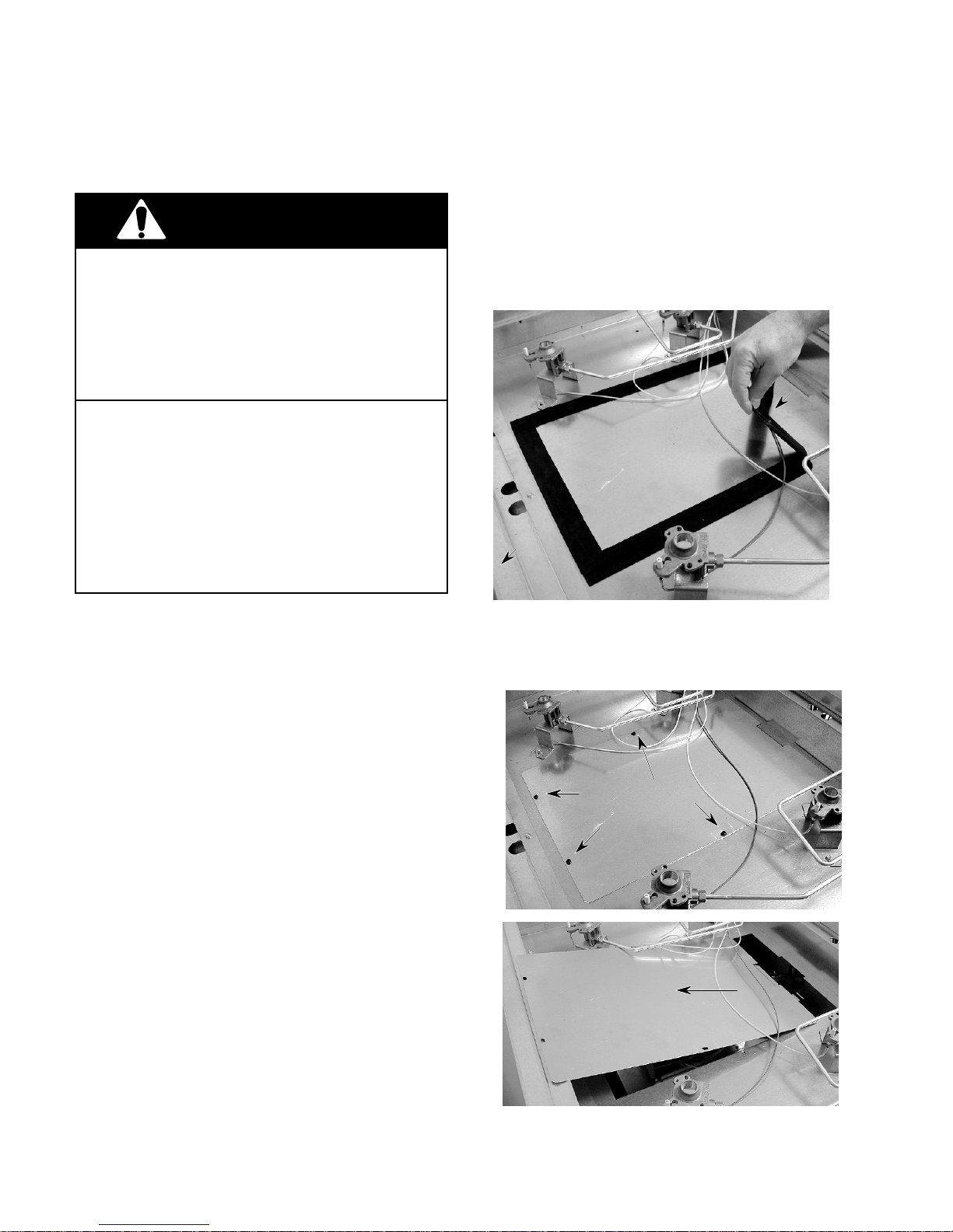
4. Starting from the front, peel off the rubber
WARNING
ELECTRICAL SHOCK HAZARD
Disconnect power before servicing the range.
Replace all panels before operating range.
Failure to do so can result in death or electrical shock.
FIRE HAZARD
Shut off gas supply line valve before servicing the range.
Check all gas line connections and replace
all panels before operating the range.
Failure to do so could result in explosion, fire,
or other injury.
tape from around the top access panel.
NOTE: Carefully peel the tape off as one
continuous piece, and do not allow the
adhesive sections to stick together.
Peel Off
Rubber
BACK
Tape
CAUTION: When you work on the dual fuel
range, be careful when handling the sheet
metal parts. Sharp edges may be present, and
you can cut yourself if you are not careful.
1. Turn off the gas and electrical power going
to the range.
2. Remove the grates, burner caps, and
burner heads from the cooktop (see page
2-2).
3. Remove the cooktop from the range (see
page 2-2).
5. To remove the access panel, remove the
four screws, raise the back, and unhook
the panel from the front.
Top Access
Panel Screws
Unhook Panel
& Slide Off At Back
2-4

The top access panel components described
on this page are shown below.
Lamp
Transformer
Control Power
Transformer
Electronic
Range Control
6. To remove the control power transformer:
7. To remove the lamp transformer:
a) Remove the screw from the mounting
bracket tab and slide the other bracket
tab out of the chassis slot.
b) Disconnect the 2 white and 2 black
wires from the terminals.
Lamp
Transformer
a) Remove the screw from the mounting
bracket tab and slide the other bracket
tab out of the chassis slot.
b) Disconnect the top (2 blue) and bottom
(red & white) wires from the terminals.
Top
Terminals
Control Power
Transformer
Screw
Screw
2 Black Wires
2 White Wires
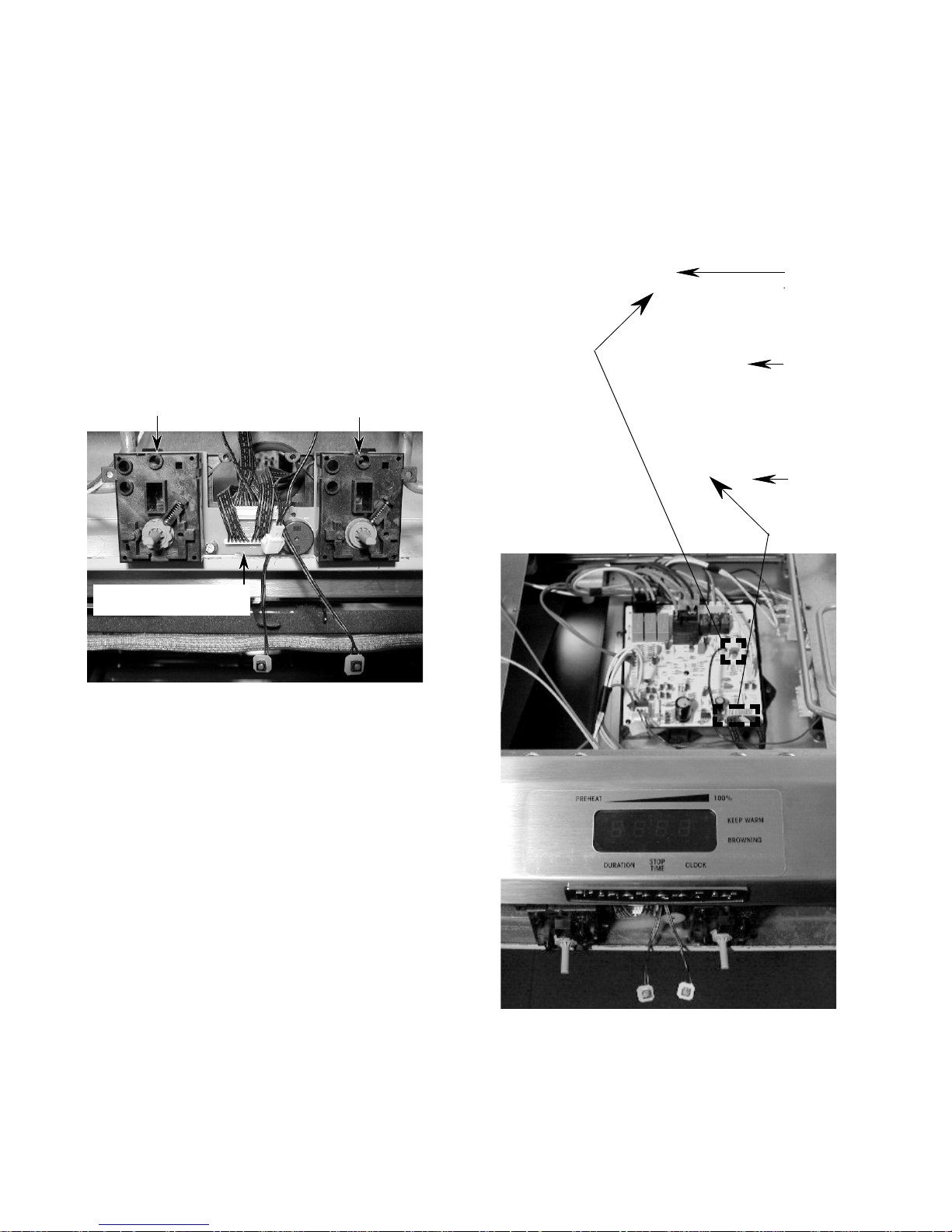
8. To remove the electronic range control:
a) Disconnect the connectors (9) and wires
(2) from the board and relay terminals.
b) Unclip the board from the plastic mount-
ing frame (4 clips).
Clip
Electronic
Range Control
Clip
Clip
Frame
Continued on the next page.
2-5
Clip
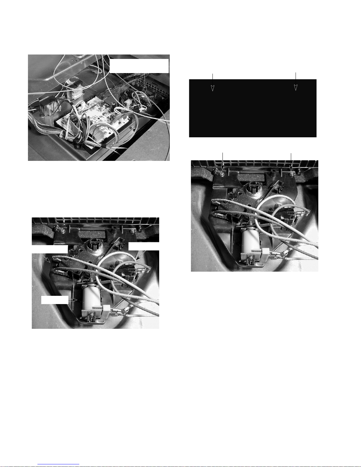
The oven door latch assembly location is shown
below.
Oven Door Latch
Assembly
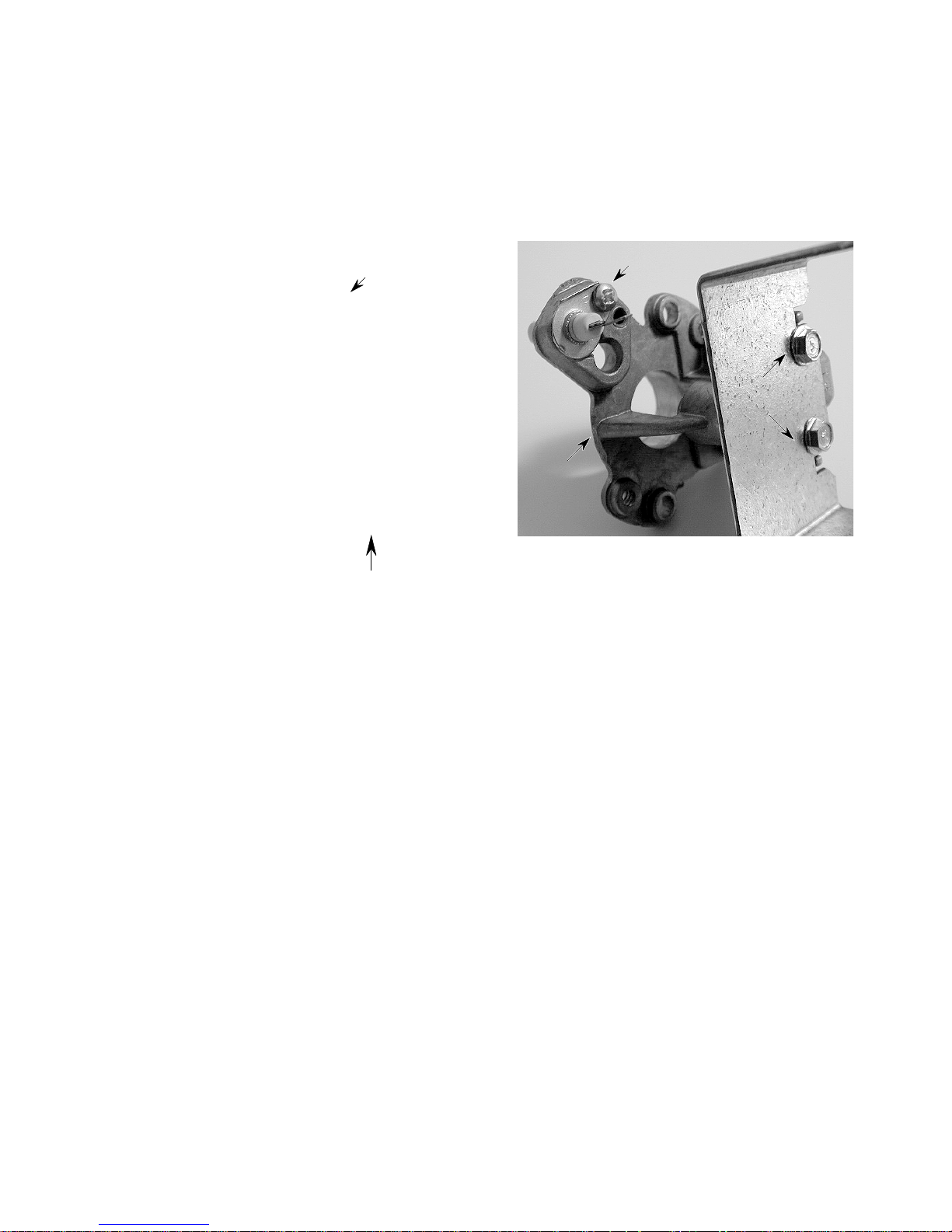
9. To remove the oven door latch assembly:
a) Disconnect the wires from the two
switches and from the solenoid terminals.
b) Remove the four screws from the front
and top of the assembly (2 at each
location).
Oven Door Latch Assembly
Front Screws
Oven Door Latch Assembly
Top Screws
Door Switch
Solenoid
Latch Switch
2-6
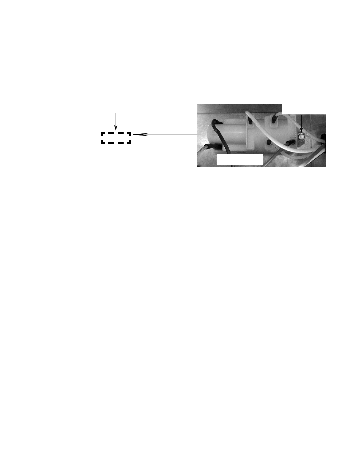
The spark module is mounted to the right side
of the range just below the front corner of the
chassis, as shown in the dashed line area
below. Access the module through the access
cutout.
10. To remove the spark module:
a) Disconnect the wires from the termi-
nals.
b) Use a 1/4˝ socket with an 8˝ extension
and remove the hex-head screw (hidden in the photo) and remove the module.
Spark Module
Access Cutout
Hex-Head
Screw
Spark Module
2-7
REMOVING THE FRONT PANEL, DISPLAY, SELECTOR &
SET CONTROLS, GAS VALVE, & IGNITION SWITCHES
b) Open the oven door and remove the
WARNING
ELECTRICAL SHOCK HAZARD
Disconnect power before servicing the range.
Replace all panels before operating range.
Failure to do so can result in death or electrical shock.
two bottom end front panel screws.
FIRE HAZARD
Shut off gas supply line valve before servicing the range.
Check all gas line connections and replace
all panels before operating the range.
Failure to do so could result in explosion, fire,
or other injury.
CAUTION: When you work on the dual fuel
range, be careful when handling the sheet
metal parts. Sharp edges may be present, and
you can cut yourself if you are not careful.
1. Turn off the gas and electrical power going
to the range.
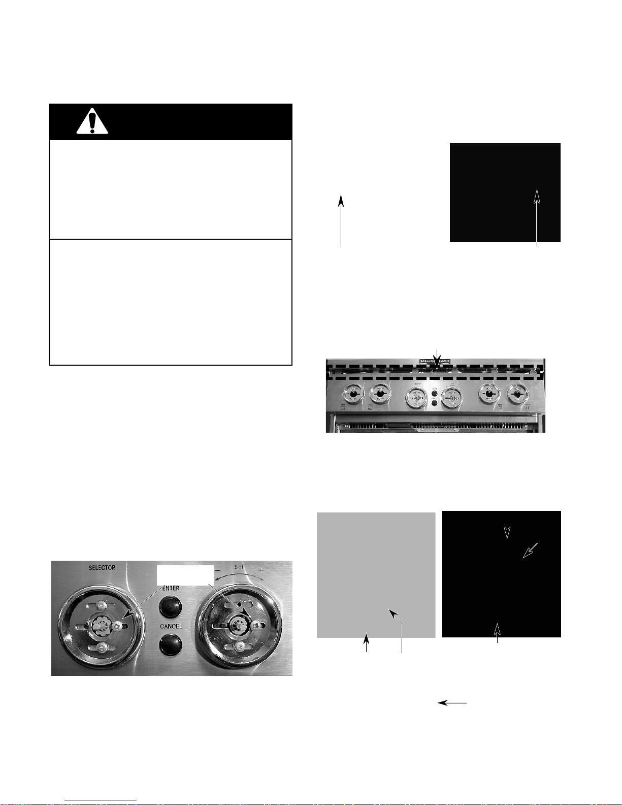
2. Remove all of the knobs from the front
panel by pulling them off the control shafts.
3. To remove the front panel:
a) Remove the two center screws from
the selector and set bezel rings.
Left Front Panel Screw Right Front Panel Screw
c) Slide the panel down so that the tabs
are out of their slots, and rotate it so that
you can access the pushbutton switches
on the back side.
Front Panel Tabs
d) Carefully unclip the small boards and
springs from the pushbutton switch
holders. Be careful not to overbend the
small clips or you will break them.
Clip
Board
Screws
2-8
Pushbutton Switches
Pushbutton Switch
Holder
Pushbutton
Spring
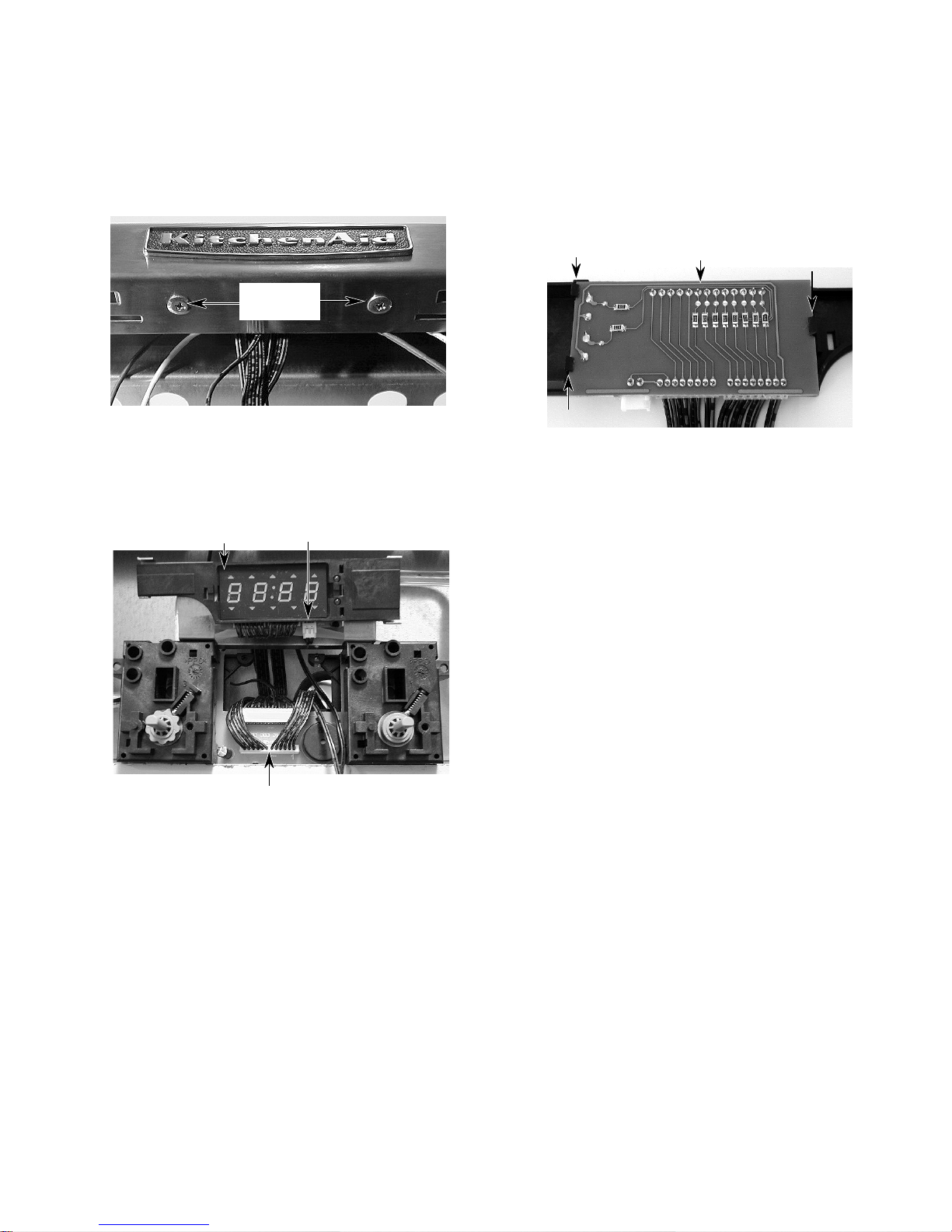
4. To remove the display:
a) Remove the front panel (see step 3 on
the previous page).
b) Remove the two display screws from
under the chassis.
e) Disconnect the 16-wire cable at the
selector and set control assembly board
connector JP01.
f) Unclip the display board from the plas-
tic holder. Be careful not to overbend
the clips or you will break them.
Display
Screws
c) Carefully remove the display and mount-
ing bracket from under the chassis.
d) Disconnect the 2-wire cable at display
board connector JP04.
Display
2-Wire Cable JP04
Clip
Clip
Display Board
Continued on the next page.
Clip
16-Wire Cable JP01
2-9
5. To remove the selector and set control
assembly:
a) Remove the cooktop (see page 2-2).
b) Remove the top access panel (see
page 2-4).
c) Remove the center screws from the
selector and set bezel rings (see step
3a on page 2-8).
d) Remove the front panel and pushbutton
boards (see pages 2-8 & 2-9).
e) Disconnect the 16-wire cable at the
selector and set control assembly board
connector JP01.
Selector Control Set Control
f) Disconnect the 2-wire cable from the
electronic range control board connector JP40.
g) Disconnect the 16-wire cable from the
electronic range control board connector JP04.
JP40
Elec-
tronic
Range
Control
Board
JP04
16-Wire Cable JP01
2-10
 Loading...